

XEL Series
Precision Linear DC
Power Supplies
XEL 15-5
XEL 30-3
XEL 60-1.5
XEL 30-3D
Operating Manual

About Xantrex
Xantrex Technology Inc. is a world-leading supplier of advanced power electronics and controls
with products from 50 watt mobile units to one MW utility-scale systems for wind, solar, batteries,
fuel cells, microturbines, and backup power applications in both grid-connected and stand-alone
systems. Xantrex products include inverters, battery chargers, programmable power supplies,
and variable speed drives that convert, supply, control, clean, and distribute electrical power.
Trademarks
XEL series is a trademark of Xantrex International. Xantrex is a registered trademark of Xantrex
International.
Other trademarks, registered trademarks, and product names are the property of their respective
owners and are used herein for identification purposes only.
Notice of Copyright
© Xantrex International. All rights reserved.
Disclaimer
UNLESS SPECIFICALLY AGREED TO IN WRITING, XANTREX TECHNOLOGY INC.
(“XANTREX”)
(a) MAKES NO WARRANTY AS TO THE ACCURACY, SUFFICIENCY OR SUITABILITY OF
ANY TECHNICAL OR OTHER INFORMATION PROVIDED IN ITS MANUALS OR OTHER
DOCUMENTATION.
(b) ASSUMES NO RESPONSIBILITY OR LIABILITY FOR LOSS OR DAMAGE, WHETHER
DIRECT, INDIRECT, CONSEQUENTIAL OR INCIDENTAL, WHICH MIGHT ARISE OUT
OF THE USE OF SUCH INFORMATION. THE USE OF ANY SUCH INFORMATION WILL
BE ENTIRELY AT THE USER’S RISK.
Date and Revision
November 2007 – Issue 1
Part Number
M370093-01
Contact Information
Telephone: 1-800-733-5427 (toll free in North America)
1-858-450-0085 (direct)
Fax: 1-858 458 0267
Email: sales@programmablepower.com
service@programmablepower.com
Web: www.programmablepower.com
1

Introduction
The New XEL series combines the traditional benefits of linear DC power supplies with new and
important features:
• Linear regulation for ultra-low output noise and fast transient recovery
• High accuracy four digit fixed-resolution meters
• True analogue controls for quick and intuitive adjustment of voltage and current
• DC output switch to check settings before applying them
• Remote voltage sensing for exceptional load regulation
• Current meter averaging to reduce jitter with rapidly varying load currents
• High power density - up to 90 watts from an ultra-compact 3U ¼-rack case size
• Significantly higher energy efficiency than conventional linear regulated designs by using
an advanced phase-controlled pre-regulator
• Low current range giving 0.1mA meter resolution and finer low current setting
• V-Span allows the user to redefine the end-stop values of the voltage control, giving high-
resolution analogue control over the exact voltage range needed
• S-Lock digitally locks voltage and current settings at the touch of a button
• Setting limits can be viewed at any time
• Safety binding post terminals are touch-proof and uniquely accept fixed shroud 4mm
plugs as well as standard plugs, bare wires and fork connectors
Table of Contents
Introduction 2
Specification 3
EMC 5
Safety 6
Installation 7
Connections 8
Operation 9
Calibration 15
Maintenance 16
Instructions en Francais 17
Bedienungsanleitung auf Deutsch 27
2
Istruzioni in Italiano 37
Instrucciones en Español 47
Warranty Information 57

Specification
General specifications apply for the temperature range 5°C to 40°C. Accuracy specifications
apply for the temperature range 18°C to 28°C after 1 hour warm-up with no load and calibration at
23°C. Typical specifications are determined by design and are not guaranteed.
OUTPUTS
Voltage/Current Ranges:
XEL 15-5 0V to 15V/1mA to 5000mA; 0V to 15V/0.1mA to 500mA
XEL 30-3 0V to 30V/1mA to 3000mA; 0V to 30V/0.1mA to 500mA
XEL 60-1·5 0V to 60V/1mA to 1500mA; 0V to 60V/0.1mA to 500mA
XEL 30-3D 0V to 30V/1mA to 3000mA; 0V to 30V/0.1mA to 500mA (each output);
0V to 30V/2mA to 6000mA; 0V to 30V/0.2mA to 1000mA (parallel mode).
Note: Actual maxima for voltage and current are typically 1% greater than the figures given above.
Voltage Setting: By coarse and fine controls.
Current Setting: By single logarithmic control.
Configuration Selection:
(XEL 30-3D only)
Voltage Span Control
(V-Span)
Settings Lock
(S-Lock)
Output Mode: Constant voltage or constant current with automatic cross-over.
Output Switch: Electronic, non-isolating.
Output Terminals: Universal 4mm safety binding posts on 19mm (0·75”) spacing for Output;
Transient Response:
Ripple and Noise
(20MHz bandwidth):
Load Regulation: For any load change, measured at the output terminals, using
Line Regulation: Voltage <0·01% + 2mV for 10% line change.
Independent, True parallel, Isolated Tracking & Isolated Ratio Tracking
modes via front panel rotary switch.
The voltage adjustment range can be controlled by digital setting of the
end-stop values of the coarse voltage control to any desired values.
The range for Vmax is 0.1V to 15V/30V/60V depending on model.
The range for Vmin is 0 to (Vmax – 0.1V).
Voltage and current settings can be locked by a single button press.
Lock accuracy is equal to meter accuracy (see Meter Specification)
CC indicator lit in constant current mode.
Preset voltage and current limit displayed when Output is off.
Output rise time with no load <15ms.
screwless terminals for Sense.
<50µs to within 50mV of setting for a 90% load change.
Normal mode voltage: <0·4mVrms and 2mVp-p
Normal mode current: <0·2mArms; <40µArms on 500mA range.
Common mode current: <5µArms
remote sense:
Voltage <0·01% + 2mV.
Add typically 2·5mV for a 0·5V drop in the positive output lead.
Specification applies for sense lead resistance <0·5Ω.
Current typically 0·01% + 500µA.
Current <0·01% + 250µA for 10% line change.
Temperature Coefficient: Voltage: typically <(50ppm + 0·5mV)/°C
Current: typically <(100ppm + 1mA)/°C;
(100ppm + 0·1mA)/°C on 500mA range.
Output Protection: Output will withstand forward voltages of up to 20V above rated output
voltage. Reverse protection by diode clamp for currents up to 3A.
OTP Protection: Output trips off for over-temperature.
3

METER SPECIFICATIONS
Display Type: Dual 4-digit meters, 10mm (0·39") LED.
Voltage: Resolution 10mV
Accuracy ± (0·1% of reading + 10mV)
Current: Resolution 1mA; 0·1mA on 500mA range.
Accuracy ± (0·3% + 3mA) to 3A, ± (0·5% + 3mA) to 6A;
± (0·3% + 0·3mA) on 500mA range.
Current Meter Average: Selects a 2s time constant (normally 20ms) for averaging of rapidly
varying load currents.
ADDITIONAL SPECIFICATIONS – XEL 30-3D
Independent Mode: Each output is fully independent and isolated. Operation is equivalent to
two single power supplies.
Tracking Mode:
Tracking Accuracy:
Ratio (%) Tracking Mode:
Tracking Accuracy:
Parallel Mode: The Master output operates as a single output power supply with twice the
Both On / Both Off: Each output has an independent DC On/Off control; these additional keys
The two outputs remain isolated but the Slave voltage controls are
disabled and the Slave voltage is set equal to the Master voltage.
Slave voltage = ±(0.1% of Master voltage setting +10mV).
As tracking but the Slave voltage controls set an output voltage between
0% and 101% of the Master voltage. Once set, varying the Master voltage
will create the same percentage change in the Slave voltage setting.
% change in Slave voltage = % change of Master voltage ± 0.1% ±10mV).
current capability (0.2mA to 6A). The Slave is disabled (its displays are
both off).
can be used to turn both outputs on or off simultaneously. These keys
operate in all four modes.
GENERAL
AC Input: 230V AC or 115V AC ± 10%, 50/60Hz. Installation Category II
Power Consumption: Single: 280VA max. Dual: 560VA max.
Operating Range: +5ºC to +40ºC, 20% to 80% RH
Storage Range:
Environmental: Indoor use at altitudes up to 2000m, Pollution Degree 2.
Cooling: Intelligent variable-speed low noise fan assists convection. Over-
Safety:
EMC: Complies with EN61326
Size: Single: 107mm x 131mm (¼ rack 3U) x 288mm, excluding feet, knobs and
Weight: Single: 4·5kg. Dual: 6.7kg.
−40ºC to + 70ºC
temperature trip shuts down output if internal temperatures exceed
predetermined thresholds.
Complies with EN61010−1
terminals.
Dual: 214mm x 131mm (½ rack 3U) x 288mm, excluding feet, knobs and
terminals.
4

This instrument has been designed to meet the requirements of the EMC Directive 89/336/EEC.
Compliance was demonstrated by meeting the test limits of the following standards:
Emissions
EN61326 (1998) EMC product standard for Electrical Equipment for Measurement, Control and
Laboratory Use. Test limits used were:
a) Radiated: Class B
b) Conducted: Class B
c) Harmonics: EN61000-3-2 (2000) Class A; the instrument is Class A by product category.
Immunity
EN61326 (1998) EMC product standard for Electrical Equipment for Measurement, Control and
Laboratory Use.
Test methods, limits and performance achieved were:
a) EN61000-4-2 (1995) Electrostatic Discharge : 4kV air, 4kV contact, Performance A.
b) EN61000-4-3 (1997) Electromagnetic Field, 3V/m, 80% AM at 1kHz, Performance B.
EMC
c) EN61000-4-11 (1994) Voltage Interrupt, 1 cycle, 100%, Performance B.
d) EN61000-4-4 (1995) Fast Transient, 1kV peak (AC line), 0·5kV peak (DC Outputs),
Performance B.
e) EN61000-4-5 (1995) Surge, 0·5kV (line to line), 1kV (line to ground), Performance B.
f) EN61000-4-6 (1996) Conducted RF, 3V, 80% AM at 1kHz (AC line only; DC Output
connections <3m not tested), Performance B.
According to EN61326 the definitions of performance criteria are:
Performance criterion A: ‘During test normal performance within the specification limits.’
Performance criterion B: ‘During test, temporary degradation, or loss of function or
performance which is self-recovering’.
Performance criterion C: ‘During test, temporary degradation, or loss of function or
performance which requires operator intervention or system reset occurs.’
Where Performance B is stated it is because DC Output regulation may deviate beyond
Specification limits under the test conditions. However, the possible deviations are still small and
unlikely to be a problem in practice.
Note that if operation in a high RF field is unavoidable it is good practice to connect the PSU to
the target system using screened leads which have been passed (together) through an absorbing
ferrite sleeve fitted close to the PSU terminals.
Cautions
To ensure continued compliance with the EMC directive observe the following precautions:
a) after opening the case for any reason ensure that all signal and ground connections are
remade correctly and that case screws are correctly refitted and tightened.
b) In the event of part replacement becoming necessary, only use components of an identical
type, see the Service Manual.
5
Safety
This instrument is a Safety Class I instrument according to IEC classification and has been
designed to meet the requirements of EN61010-1 (Safety Requirements for Electrical Equipment
for Measurement, Control and Laboratory Use). It is an Installation Category II instrument
intended for operation from a normal single phase supply.
This instrument has been tested in accordance with EN61010-1 and has been supplied in a safe
condition. This instruction manual contains some information and warnings which have to be
followed by the user to ensure safe operation and to retain the instrument in a safe condition.
This instrument has been designed for indoor use in a Pollution Degree 2 environment in the
temperature range 5°C to 40°C, 20% - 80% RH (non-condensing). It may occasionally be
subjected to temperatures between +5°C and –10°C without degradation of its safety. Do not
operate while condensation is present.
Use of this instrument in a manner not specified by these instructions may impair the safety
protection provided. Do not operate the instrument outside its rated supply voltages or
environmental range.
WARNING! THIS INSTRUMENT MUST BE EARTHED
Any interruption of the mains earth conductor inside or outside the instrument will make the
instrument dangerous. Intentional interruption is prohibited. The protective action must not be
negated by the use of an extension cord without a protective conductor.
When the instrument is connected to its supply, terminals may be live and opening the covers or
removal of parts (except those to which access can be gained by hand) is likely to expose live
parts. The apparatus shall be disconnected from all voltage sources before it is opened for any
adjustment, replacement, maintenance or repair.
Capacitors inside the power supply may still be charged even if the power supply has been
disconnected from all voltage sources but will be safely discharged about 10 minutes after
switching off power.
Any adjustment, maintenance and repair of the opened instrument under voltage shall be avoided
as far as possible and, if inevitable, shall be carried out only by a skilled person who is aware of
the hazard involved.
If the instrument is clearly defective, has been subject to mechanical damage, excessive moisture
or chemical corrosion the safety protection may be impaired and the apparatus should be
withdrawn from use and returned for checking and repair.
Make sure that only fuses with the required rated current and of the specified type are used for
replacement. The use of makeshift fuses and the short-circuiting of fuse holders is prohibited.
Do not wet the instrument when cleaning it.
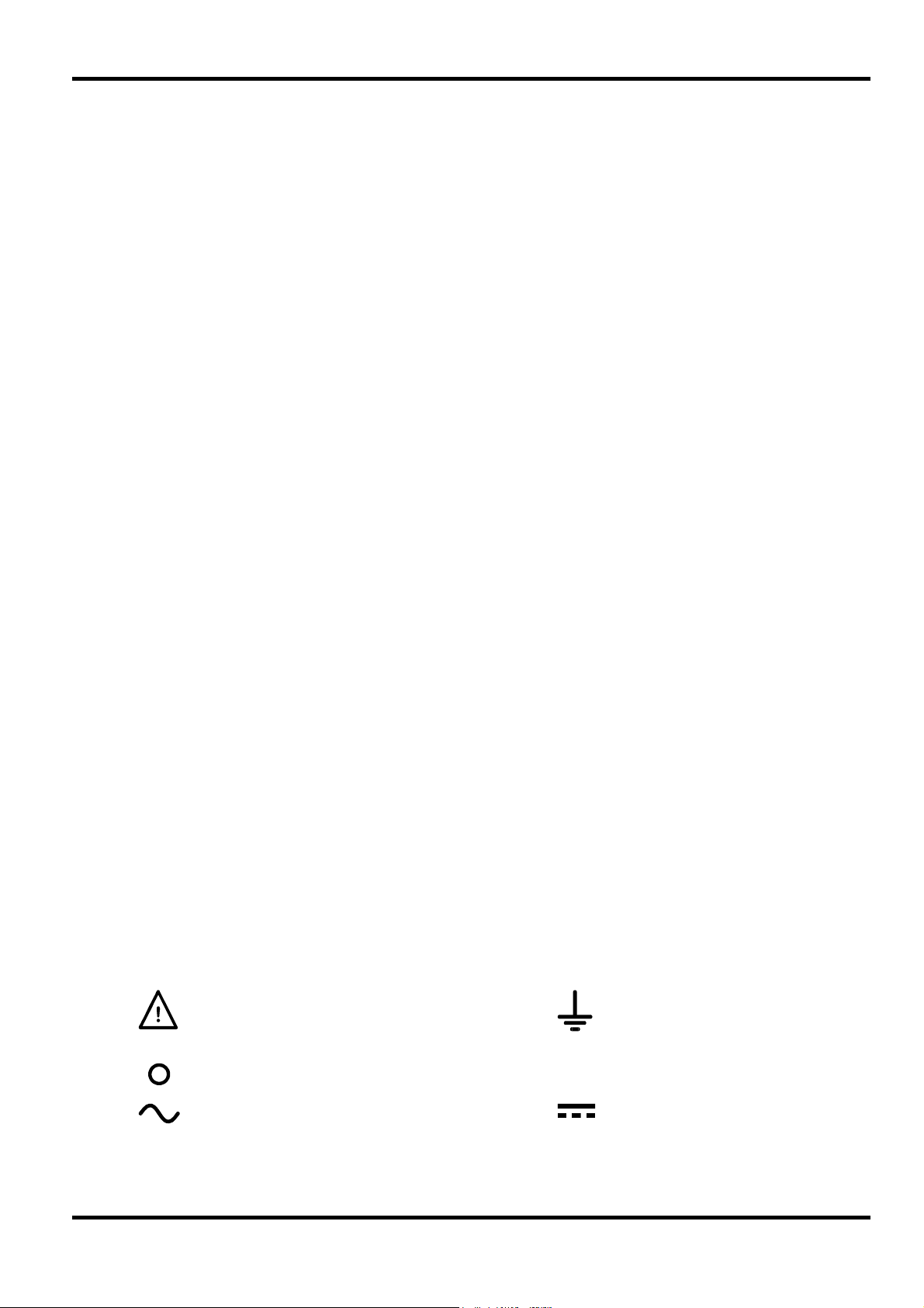
The following symbols are used on the instrument and in this manual:-
Caution - refer to the accompanying documentation, incorrect operation
may damage the instrument.
6
l
Earth (ground) terminal.
mains supply OFF.
mains supply ON.
alternating current (ac)
direct current (dc)
Mains Operating Voltage
Check that the instrument operating voltage marked on the rear panel is suitable for the local supply.
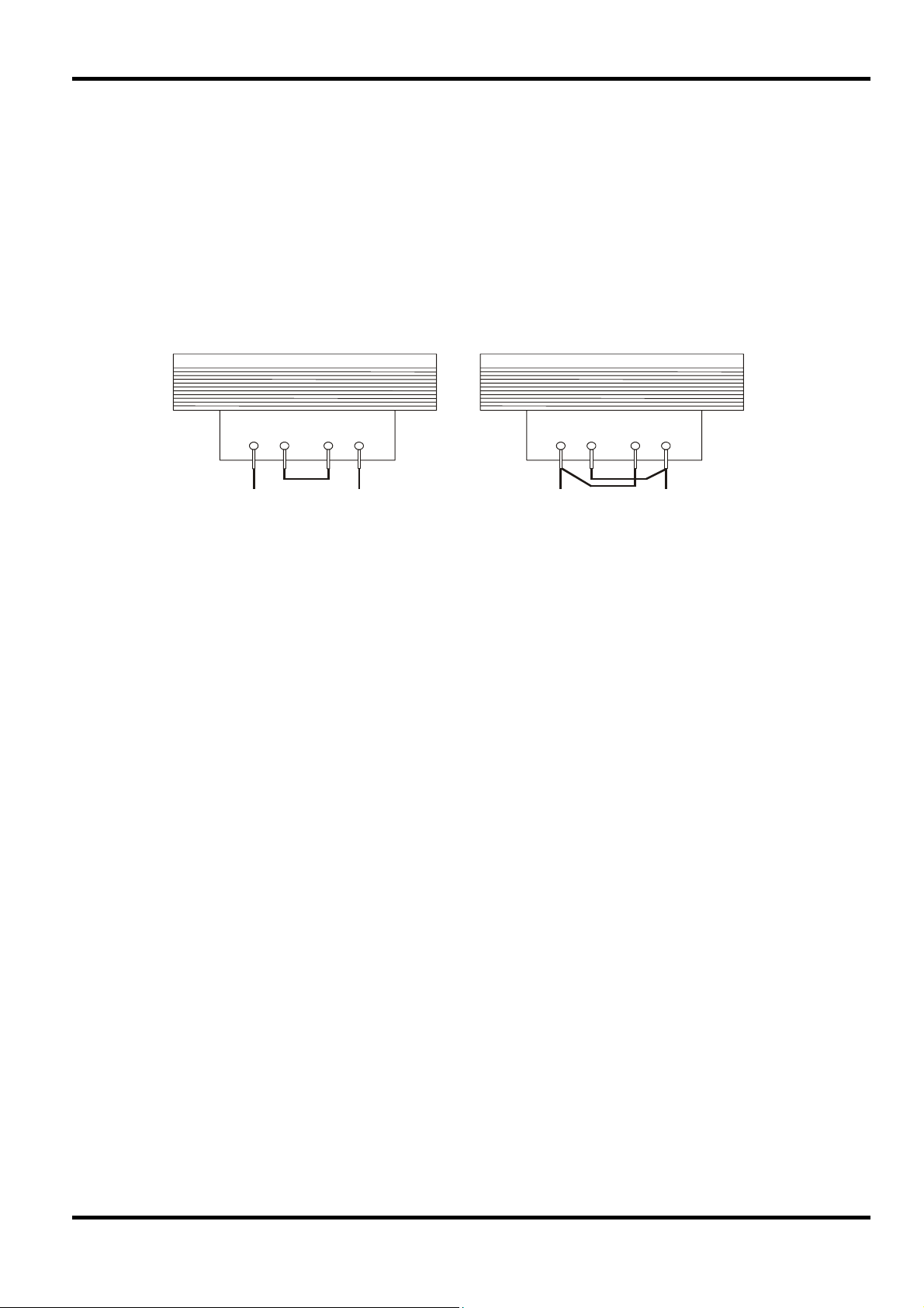
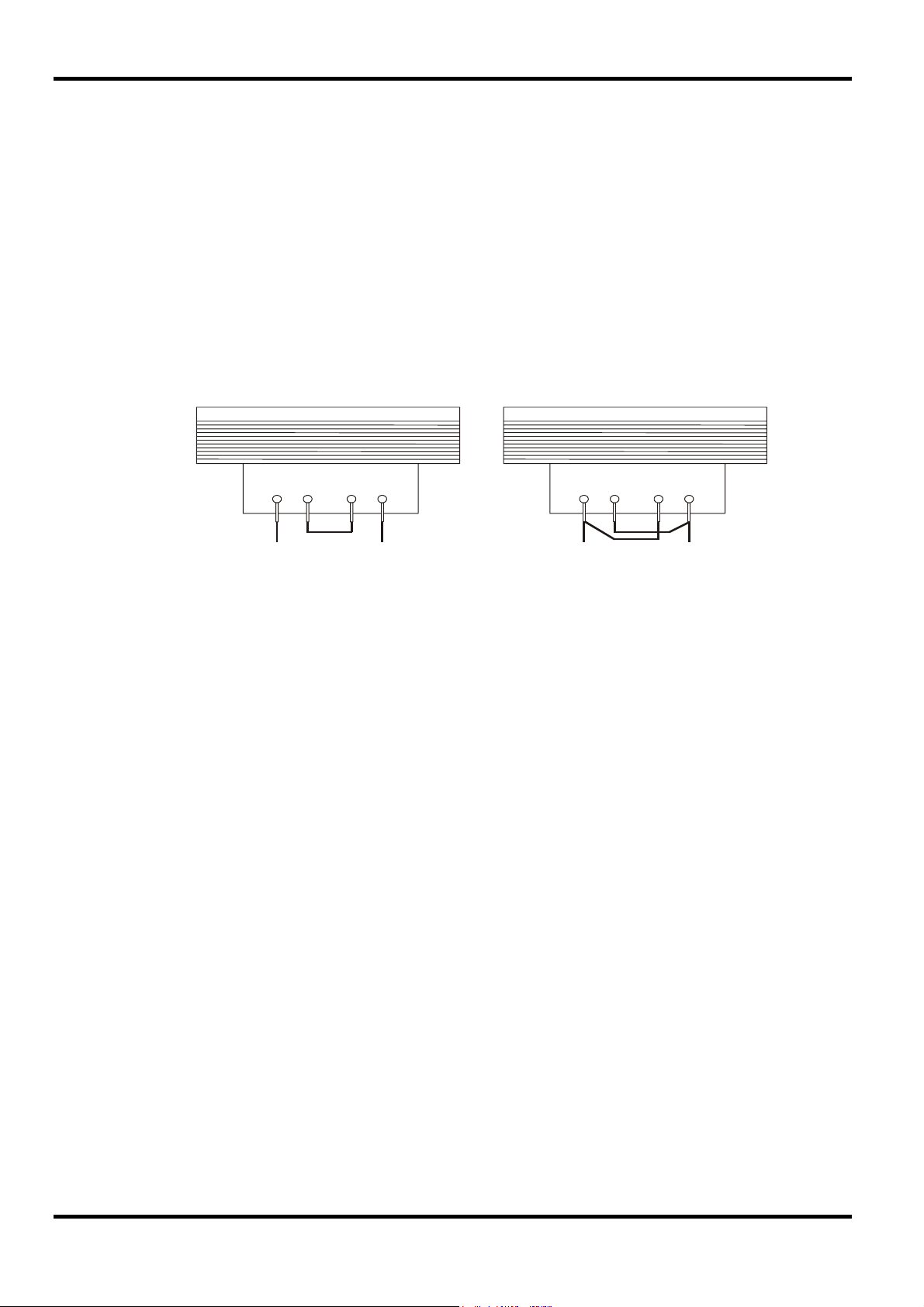
Should it be necessary to change the operating voltage, proceed as follows:
1. Ensure that the instrument is disconnected from the AC supply.
2. Remove the plastic push-rivets at each side edge of the top cover. Use the blade of a small
screwdriver to first ease out the rivet head and then fully remove the rivet body. Remove the two
rear panel screws securing the top cover; slide the cover back and lift off.
3. Change the transformer connections (two transformers on the dual) following the diagrams:
4. Re-assemble in the reverse order. To comply with safety standard requirements the operating
voltage marked on the rear panel must be changed to clearly show the new voltage setting.
230V Operation 115V Operation
BLUE BROWN BLUE BROWN
Fuse
The AC fuse is located in the fuse drawer in the lower part of the IEC inlet connector. To change the
fuse remove the line cord and open the fuse drawer with a suitable tool.
The correct fuse type is 20 x 5mm 250V HBC time-lag with the following rating:
Installation
Make sure that only fuses with the required current rating and of the specified type are used for
replacement. The use of makeshift fuses and the short-circuiting of fuseholders are prohibited.
Mains Lead
Connect the instrument to the AC supply using the mains lead provided. Should a mains plug be
required for a different mains outlet socket, a suitably rated and approved mains lead set should be
used which is fitted with the required wall plug and an IEC60320 C13 connector for the instrument
end. To determine the minimum current rating of the lead-set for the intended AC supply, refer to the
power rating information on the equipment or in the Specification.
Any interruption of the mains earth conductor inside or outside the instrument will make the instrument
dangerous. Intentional interruption is prohibited.
Mounting
This instrument is suitable both for bench use and rack mounting. A rack kit for mounting in a 19” rack
is available from the Manufacturers or their overseas agents.
Ventilation
The power supply is cooled by an intelligent multi-speed fan which aids vertical convection. Take care
not to restrict the air inlets underneath or the vents on the top. When rack-mounted allow adequate
space above and below the instrument and/or use a fan tray for forced cooling.
230V 115V
Single: 1.6A (T) 3.15A (T)
Dual: 3.15A (T) 6.3A (T)
WARNING! THIS INSTRUMENT MUST BE EARTHED.
7
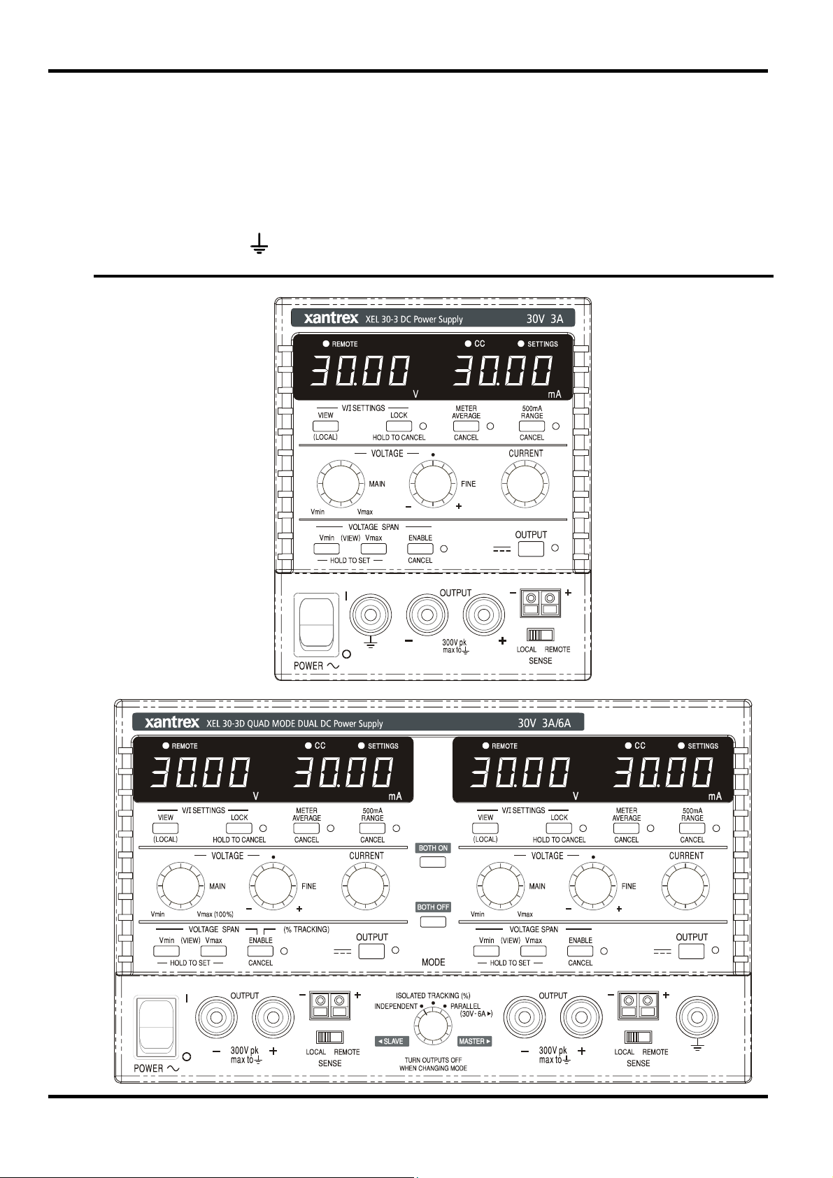
Connections
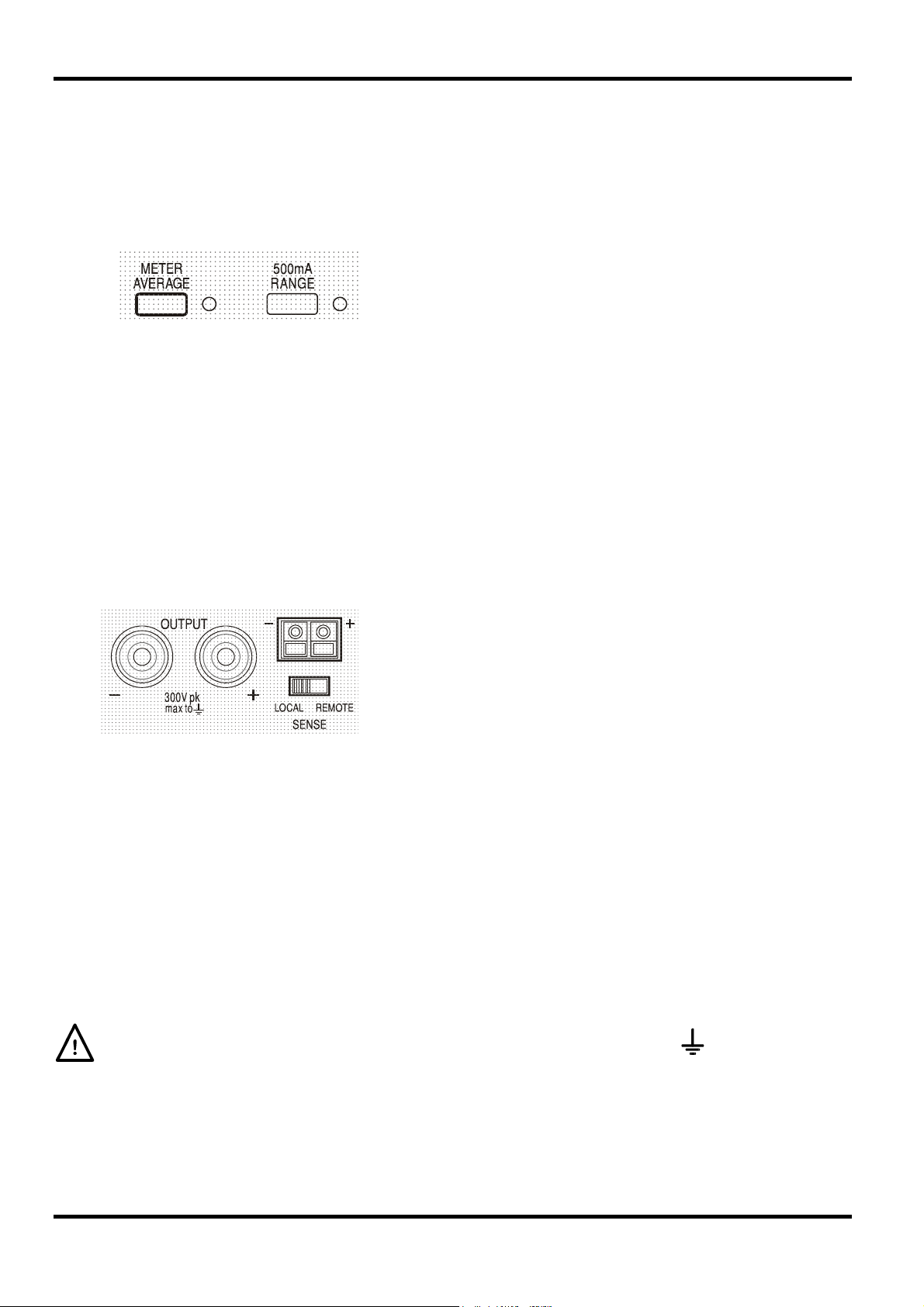
All connections are made from the front panel.
The load should be connected to the positive (red) and negative (black) terminals marked
OUTPUT. Both are fully floating and either can be connected to ground.
Remote sense connections to the load, if required, are made from the positive (+) and
negative (−) SENSE terminals. Switch the LOCAL/REMOTE switch to REMOTE when remote
sensing is required. Switch back to LOCAL when remote sensing is not in use.
The terminal marked
is connected to the chassis and safety earth ground.
FRONT PANEL VIEW
(Single and Dual)
8
In this manual front panel keys, controls and sockets are shown in capitals, e.g. CURRENT,
OUTPUT, LOCK. Messages displayed on the 7-segment LEDs are shown in a different type-font,
e.g. turn oFF, OtP trip. The additional features of the Quad-mode Dual instrument are
described together at the end of this chapter.
Switching On and Power-On Conditions
The POWER switch is located at the bottom left of the front panel. When the POWER switch is
turned on (
shows Volts and Amps.
At power on, the factory default setting is for the output to be OFF. All other settings will be the
same as they were at last power off.
l ) the right hand meter briefly indicates the firmware revision before the display
Operation
After 2 seconds the new setting is shown continuously in the display and the change is
implemented; release the OUTPUT and VIEW keys. Repeating the procedure will change the
setting back to the previous state. Note that the power-on status of the two outputs of the dual
supply need to be set individually.
Output Control
Setting Up the Output
With the POWER switch on and the OUTPUT off the output voltage and current limit can be
accurately preset using the VOLTAGE and CURRENT controls; the left-hand meter shows the set
voltage, the right-hand meter shows the set maximum current and the SETTINGS indicator is lit.
When the output switch is switched on, the OUTPUT indicator lights; the left-hand meter now
shows the actual voltage and the right-hand meter the actual load current.
To change the current limit range the output must be switched off; if the output is on the warning
message
range remains unchanged.
turn oFF is shown briefly in the display, the OUTPUT indicator flashes and the
The dc output state at power-on can be set to be ‘always off’ or ‘same as
at last power-off’. The setting can be changed as follows. With the VIEW
key held down, press and hold down the
will first show the present setting for 1 second (
default is still selected) before flashing the new setting for 2 seconds (
OUTPUT key; the display
OP OFF if the factory
LASt Set in this instance).
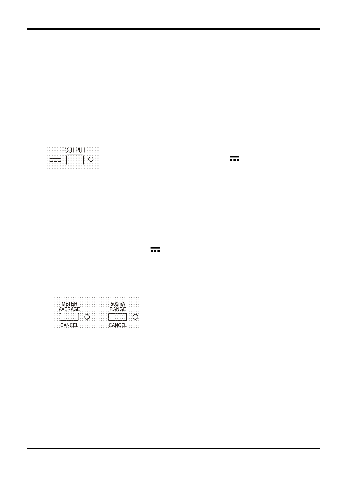
The upper limit of the CURRENT control can be switched
between the maximum for this model and 500mA with
alternate presses of the 500mA RANGE key to give finer
current limit setting and measurement resolution (0.1mA up to
500mA); the indicator beside the key is lit when the 500mA
range is selected.
Constant Voltage
The output voltage is adjusted using the main and fine VOLTAGE controls; the CURRENT control
sets the maximum current that can be supplied.
Constant Current
If the load resistance is low enough such that, at the output voltage set, a current greater than the
current limit setting would flow, the power supply will automatically move into constant current
operation. The current output is adjusted by the CURRENT control and the VOLTAGE controls
set the maximum voltage that can be generated.
The CC indicator lights to show constant current mode.
9
Instantaneous Current Output
The current limit control can be set to limit the continuous output current to levels down to 1mA
(0.1mA on 500mA range). However, in common with all precision bench power supplies, a
capacitor is connected across the output to maintain stability and good transient response. This
capacitor charges to the output voltage and loading of the output will produce a current pulse as
the capacitor discharges which is independent of the current limit setting.
Current Meter Averaging
Efficiency
The power supply minimises dissipation by using electronic line frequency pre-regulation to
maintain a low overhead voltage to the output regulators. In addition, to optimise operation at
extremes of line input voltage and DC output power, the transformer secondary is intelligently tapchanged by a relay. Hysteresis is used at the threshold point to prevent unnecessary switching
when the output is set at about that level. Apart from an audible ‘click’ the user will be unaware
that the relay has switched; there will be no disturbance on the output.
Connection to the Load
To reduce the measurement jitter with rapidly varying load currents
a 2-second time constant can be selected by pressing the METER
AVERAGE key; the indicator beside the key lights when meter
averaging is selected. Press the key again to CANCEL meter
averaging and return to the standard 20ms time constant.
The load should be connected to the positive (red) and negative (black) OUTPUT terminals. Both
are fully floating and either can be connected to ground.
Remote Sensing
This requires the sense terminals to be connected to the output at the load instead of at the
source; insert wires into the spring-loaded SENSE terminals and connect directly to the load.
Switch the LOCAL/REMOTE switch to REMOTE. To avoid instability and transient response
problems, care must be taken to ensure good coupling between each output and sense lead. This
can be done either by twisting the leads together or by using coaxially screened cables (sense
through the inner). An electrolytic capacitor directly across the load connection point may also be
beneficial.
The voltage drop in each output lead must not exceed 0.5 Volts.
Switch the LOCAL/REMOTE switch back to LOCAL when remote sensing is not in use.
The unit has a very low output impedance, but this is inevitably
increased by the resistance of the connecting leads. At higher
currents this can result in significant differences between the
indicated source voltage and the actual load voltage (two 20mΩ
connecting leads will drop 0.2V at 5 Amps, for instance). This
problem can be minimised by using short, thick, connecting
leads, but where necessary it can be completely overcome by
using the remote sense facility.
Series or Parallel Connection with Other Outputs
The outputs of the power supply are fully floating and may be used in series with other power
supply units to generate high DC voltages up to 300V DC.
10
The maximum permissible voltage between any terminal and earth ground (
WARNING! Such voltages are exceedingly hazardous and great care should be taken to shield
the output terminals for such use. On no account should the output terminals be touched when
the unit is switched on under such use. All connections to the terminals must be made with the
power switched off on all units.
It should be noted that the unit can only source current and cannot sink it, thus units cannot be
series connected in anti-phase.
) is 300VDC
y
The unit can be connected in parallel with others to produce higher currents. Where several units
are connected in parallel, the output voltage will be equal to that of the unit with the highest output
voltage setting until the current drawn exceeds its current limit setting, upon which the output will
fall to that of the next highest setting, and so on. In constant current mode, units can be
connected in parallel to provide a current equal to the sum of the current limit settings.
Protection
The output has intrinsic short-circuit protection and is protected from reverse voltages by a diode;
the continuous reverse current must not exceed 3 Amps, although transients can be much higher.
If the applied reverse voltage can source more current than the set current limit, and the output is
on, then the output will go into current limit (the CC indicator will flash) and its display will show
the reverse voltage across the protection diode; if the output is off, just the CC indicator will flash.
In common with all series regulated single-ended power supplies, the unit is not capable of
sinking current provided from an external source. If a voltage greater than the set output voltage
of the unit is applied from an external source, the internal regulator will turn off and no current will
flow; if the output is turned on the voltage meter will read the applied voltage. No damage will
result providing the applied voltage does not exceed the maximum output voltage of the power
supply by more than 20 Volts.
With the OUTPUT off the load is still connected to the power supply output stage; the output
voltage is simply set to zero. Do not apply external voltages to the power supply terminals in
excess of 20V above the rated output voltage, even with the output off, or damage may result.
Over-temperature Protection
An internal sensor will detect over-temperature due to blocked airflow, fan failure or other circuit
fault. Over-temperature will turn the output off, the OUTPUT indicator will flash, and the display
will show the message
removed, and the instrument has cooled down, the output indicator will go off but the message
OtP triP . When the cause of the over-temperature has been
OtP triP continues to show. Pressing the OUTPUT key once will change the display to show
the preset voltage and current (the SETTINGS indicator will be lit) but the output will remain off;
pressing it a second time will turn the output on normally.
If the OUTPUT key is pressed while the instrument is still over-temperature (OUTPUT indicator is
flashing), the message
SETTINGS indicator will be lit) but the output will remain off; each subsequent press of the
OUTPUT key causes the
off until the over-temperature condition ends.
OtP triP is replaced by the preset voltage and current (the
OtP triP message to be displayed briefly but the output will remain
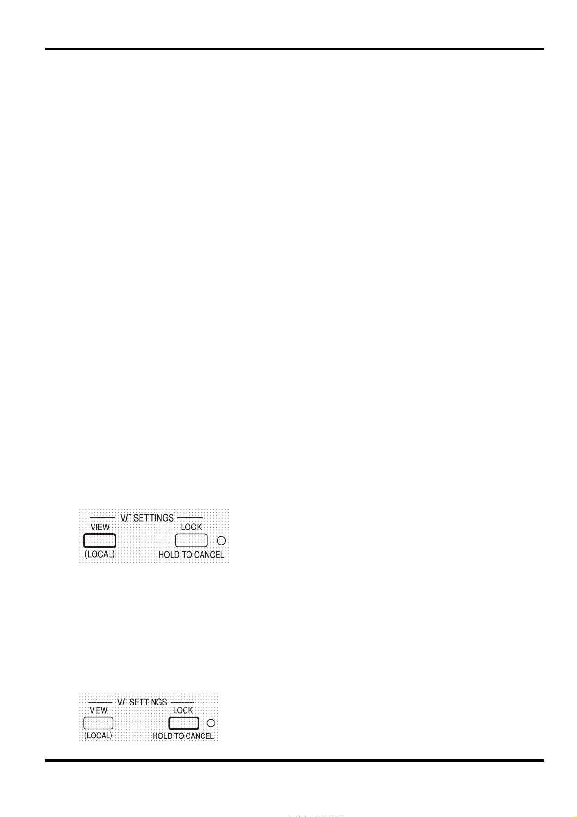
View Settings
The set voltage and current limit are always shown when
the output is off but can also be viewed when the output is
on by pressing the VIEW key; the SETTINGS indicator is lit
whilst the VIEW ke
is pressed.
Lock Settings
Pressing the LOCK key digitally locks the set voltage and current limit. The settings are stored
with a precision of better than 1 digit. Subsequent adjustments of the VOLTAGE and CURRENT
controls will have no effect.
Because cancelling LOCK will cause the output settings to change if the VOLTAGE and
CURRENT control positions have been moved, warning reminders are given before LOCK is
cancelled. Press and hold the key to cancel LOCK.
If the OUTPUT is off (the safe condition) the display will flash the ‘unlocked’ settings twice before
the change is implemented; the LOCK lamp goes off.
11
If the output is still on, OP on (output on) will flash twice in the
display, followed by flashing of the new ‘unlocked’ settings for 2-3
seconds (slowly at first, then faster) before the change is finally
implemented; the LOCK lamp goes off when the change is made.
Releasing the LOCK key at any time while the display is flashing will abort the LOCK cancellation.
Attempting to change the current limit range (see Setting up the Output section) or the voltage
span limits (see Voltage Span section) with LOCK enabled is not allowed; if attempted, the
message
Unloc is shown briefly in the display and the LOCK indicator is also flashed. If the
output is also on when these actions are attempted the message
the display (accompanied by the output indicator flashing) followed by the message
(with the LOCK indicator flashing).
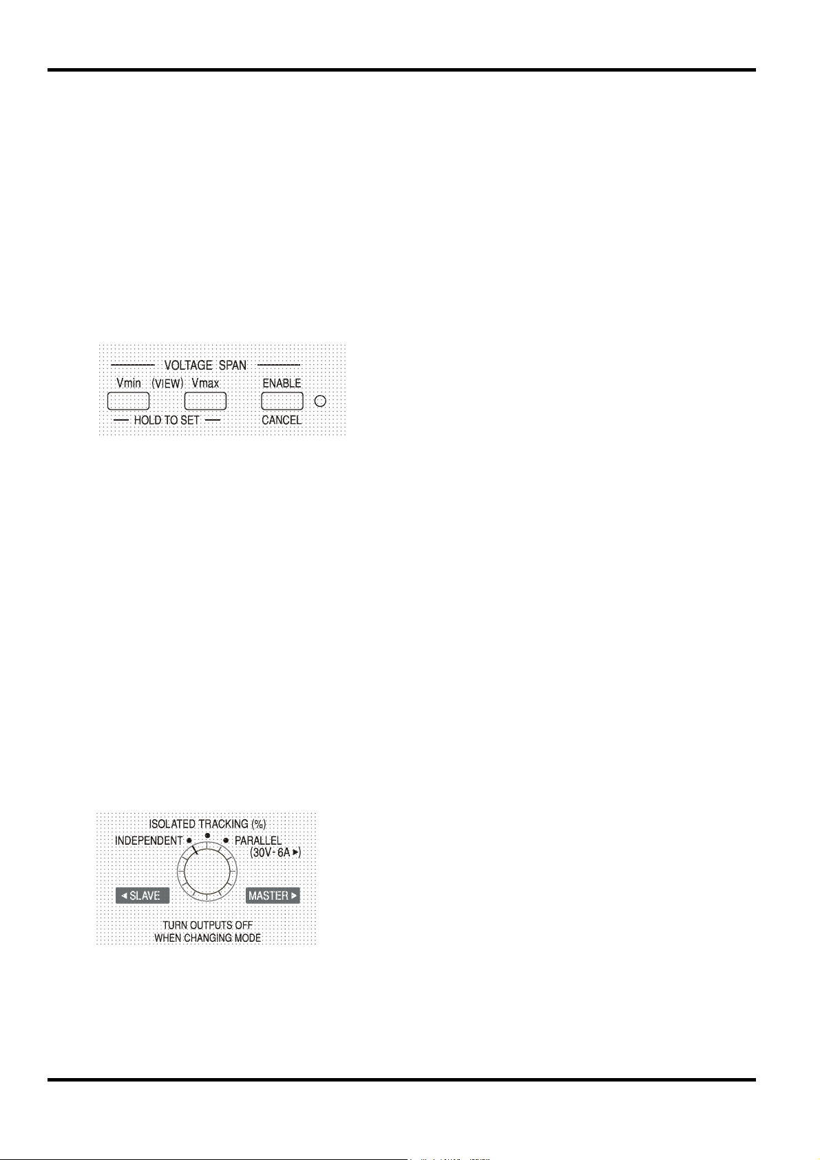
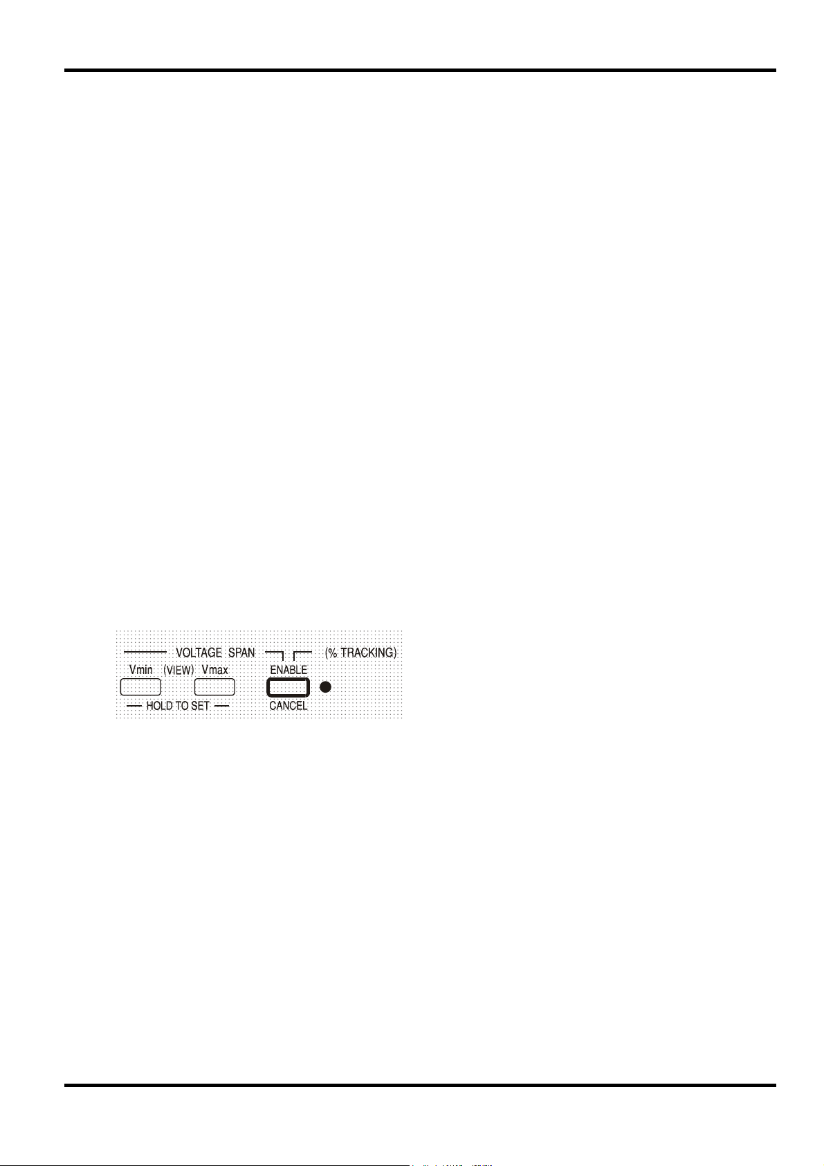
Using Voltage Span
The VOLTAGE SPAN (V-Span) capability allows the end-stop values of the VOLTAGE controls to
be redefined by the user such that the controls operate within a specific, narrower, voltage range.
This not only has the advantage of protecting against the accidental application to the load of
voltages outside of the range, but also provides high-resolution analogue control over the
specified voltage range using the full 300º rotation of the voltage controls.
turn oFF is first shown in
V-Span is turned on or off with the ENABLE key. The
ENABLE lamp is lit when V-Span is selected. The
factory default is V
= 3V, V
min
max
= 5V
Unloc
Because turning V-Span on will always change the output voltage, it can only be enabled or
cancelled with the output off. If attempts are made to enable or cancel V-Span with the output on,
the display will briefly show the message
To set new values for V
min
or V
the V-Span function must be off (cancelled).
max
turn oFF to prompt the user to turn the output off.
The lower voltage limit is defined by using the MAIN and FINE VOLTAGE controls to set exactly
the required value; the V
key is then held pressed until the left-hand side (V) display stops
min
flashing and the right-hand side (mA) display shows
time by a short press (<1 second) of the V
key. The upper voltage limit is set and VIEWed in
min
exactly the same way using the VOLTAGE controls and the V
The limits can be set in any order and to any value within the output range of the instrument but
V-Span can only be turned on with the ENABLE key if V
met, the message
Set Err is briefly displayed and the V-Span function is not implemented.
When V-Span is enabled, the range of the MAIN VOLTAGE control is exactly V
the FINE control is set at its mid-point, marked on the panel with a • . The FINE control itself
can be usefully used to give an additional fine adjustment of ±1% (of the voltage span).
Mode Control of the Quad-Mode Dual
However, it is not possible to guarantee that there will never be any unwanted transients as the
mode is switched and the recommendation is therefore that both outputs should always be
switched off before any mode change.
The four operating modes of the Quad-Mode Dual are
described below; the mode is changed using the MODE
rotary switch. To prevent unintended voltages being
accidentally applied to the circuits connected to the outputs,
changing modes will always cause both outputs to be
switched off.
Set. The setting can be VIEWed at any
key.
max
max
≥ (V
+ 0.1V); if this condition is not
min
to V
min
max
when
12
Independent
Set the MODE switch to INDEPENDENT. The two outputs are completely independent and
electrically isolated; each can be set as described in the preceding Output Control section.
It is not possible to switch from Independent mode to Tracking with LOCK set on the Slave
output. The message
off (in Independent mode) before the Tracking modes can be used.
See also the Retained Slave Settings paragraph.
Isolated Tracking
Set the MODE switch to ISOLATED TRACKING. The two outputs remain electrically isolated but
the Voltage controls of the Master output set an identical voltage on the Slave output. The
Current controls of the Slave remain independent, including the 500mA Range and Meter
Average functions.
The electrical isolation permits the two outputs to be connected to provide, for example, tracking
voltages of opposite polarity or identical voltages connected to different system references (e.g.
digital ground and analogue ground).
The LOCK and VOLTAGE SPAN functions of the Master operate exactly as described previously
and, because the output voltage of the Slave tracks the Master, they control the Slave output
voltage as well. Note that only the output voltage of the Slave is ‘locked’ when the Master LOCK
is used; the current controls of the Slave, including the 500mA Range and Meter Average
functions, remain independent.
The LOCK key on the Slave output is ignored and pressing it causes the message
be shown momentarily in the Slave display as a reminder.
It is possible to switch from Tracking mode back to Independent mode with LOCK still set on the
Master. The ‘Master’ (right-hand output) settings stay ’locked’ but the settings of the left-hand
output, are not locked.
The Voltage Span keys of the Slave have a different function in Tracking mode, see next section.
Un loc is shown in the Slave display and LOCK must first be switched
In trac to
Isolated Ratio (%) Tracking
Set the MODE switch to ISOLATED TRACKING.
The instrument operates as described above for Tracking mode but the Slave voltage can be set
to a percentage (0% to 101%) of the Master voltage using the Slave Voltage controls. The ratio is
then maintained as the Master voltage is varied.
Pressing ENABLE again returns the Slave to standard Tracking mode (ENABLE lamp off).
Ratio Tracking can only be enabled or disabled with the output off. If the output is on the display
will briefly show the message
implemented.
Whenever Ratio Tracking mode is enabled the Slave display momentarily shows Pcnt on
before reverting to show the actual output voltage now set.
The percentage value can be shown at any time by pressing either the V
Slave output. With either key held down the Slave display shows the percentage setting in the
form
90.0 Pcnt and the Slave Voltage controls can be used to set the ratio percentage
required. The ratio percentage can be set prior to Ratio Tracking being enabled (ENABLE lamp
off).
The LOCK and VOLTAGE SPAN functions of the Master operate exactly as described previously.
However, with Ratio Tracking enabled, the Slave Voltage controls can still be used to adjust the
ratio percentage of the Slave voltage even though the Master voltage is locked. See also the
Retained Slave Settings paragraph.
Ratio Tracking is enabled by pressing the
ENABLE key in the Slave VOLTAGE SPAN
section (ENABLE lamp on)
turn oFF when ENABLE is pressed and the change will not be
min
or V
key of the
max
13
Parallel
The MODE switch is set to PARALLEL. The instrument operates in true parallel mode with all of
the power available from the Master output which can then supply up to 6 amps. The Slave
output is disabled and its displays are turned off.
In Parallel mode the value of the current limit is doubled for the same setting of the Current limit
control, including the 500mA range which becomes 1000mA max; as a warning, when Parallel
mode is first selected, the current display flashes twice before steadily displaying the new limit.
Similarly, the current display is flashed twice when the mode is changed from Parallel to Tracking,
as a warning that the Master output current limit has now halved.
The LOCK and VOLTAGE SPAN functions of the Master operate exactly as described previously.
It is possible to switch from Parallel mode back to Tracking mode (and vice-versa) with LOCK still
set on the Master; both the Voltage and Current controls of the Master stay in LOCK, as
described previously. However, the actual set current limit of the Master will still double (switching
from Tracking to Parallel) or halve (switching from Parallel to Tracking), even though LOCK is set,
but the current display flashes as a warning that this has happened.
Retained Slave Settings
If V-Span is enabled on the Slave output in INDEPENDENT mode, it is disabled when TRACKING
mode is selected but re-enabled when INDEPENDENT mode is re-selected.
If Ratio (%) Tracking is enabled on the Slave output in TRACKING mode, it is disabled when
INDEPENDENT or PARALLEL are selected but re-enabled when TRACKING mode is reselected.
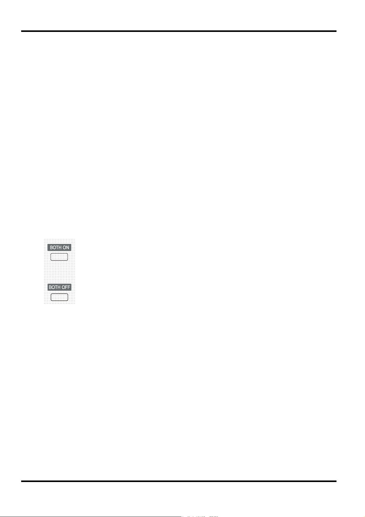
Simultaneous Output On/Off Control
The Both On / Both Off keys are in addition to the individual OUTPUT switches
and permit both outputs to be turned on or off synchronously with a single key
press. The Both On / Both Off keys operate in all four configuration modes.
14

Routine calibration is carried out without opening the instrument. Allow a 10 minutes warm-up
before commencing calibration.
Equipment Required
A 5½ digit multimeter with better than 0.02% accuracy on dc volts and better than 0.06%
accuracy on dc current (to 5A). Alternatively use a precision shunt for current measurement.
Calibration
Calibration
Calibration mode is entered by holding down all three VOLTAGE SPAN keys (V
ENABLE) while the POWER switch is turned on (
indicator lamps will be lit, as a display test. When the VOLTAGE SPAN keys are released the
display will show the first calibration step and the ENABLE lamp will blink slowly.
In calibration mode V
each step the calibration must first be made 'active' by pressing the ENABLE key; the ENABLE
lamp blinks rapidly when calibration is active and the calibration value is adjusted using the MAIN
and FINE VOLTAGE controls. If ENABLE is not pressed at any step, calibration is not activated
at that step and the existing calibration value is retained when the step is exited.
During calibration the left-hand display shows the calibration value and the right-hand display
shows the step number. Some values are 5-digit, in which case the 5
hand digit of the right-hand display.
Some steps adjust values on the display and some adjust the output. When a step adjusts the
output, measured by the DMM, the left-hand display shows a number.
Calibration must be done in sequence. However, it is possible to pass through a step, without
making an adjustment, providing ENABLE is not pressed, see above.
The full procedure is detailed in the table. Steps 3 and 8 are model dependent; note that the
15V/5A model is calibrated at 3A to minimise errors.
Note that the CURRENT control must be at minimum for step 5.
The
change load message between steps 7 and 8 is the point at which the high current
range must be selected on the DMM.
steps forward to the next adjustment and V
max
l ). All the display segments and other
steps backwards. At
min
th
digit is shown in the left-
min
, V
max
and
The final step in the sequence (step 14) shows
stores the new calibration values and reboots the instrument in the normal operating mode. Until
this is done the new values are not stored permanently. Turning POWER off (
will retain all the old calibration values.
15
End. Pressing the ENABLE key for 2½ seconds
) at any point
(Calibration Table overleaf)
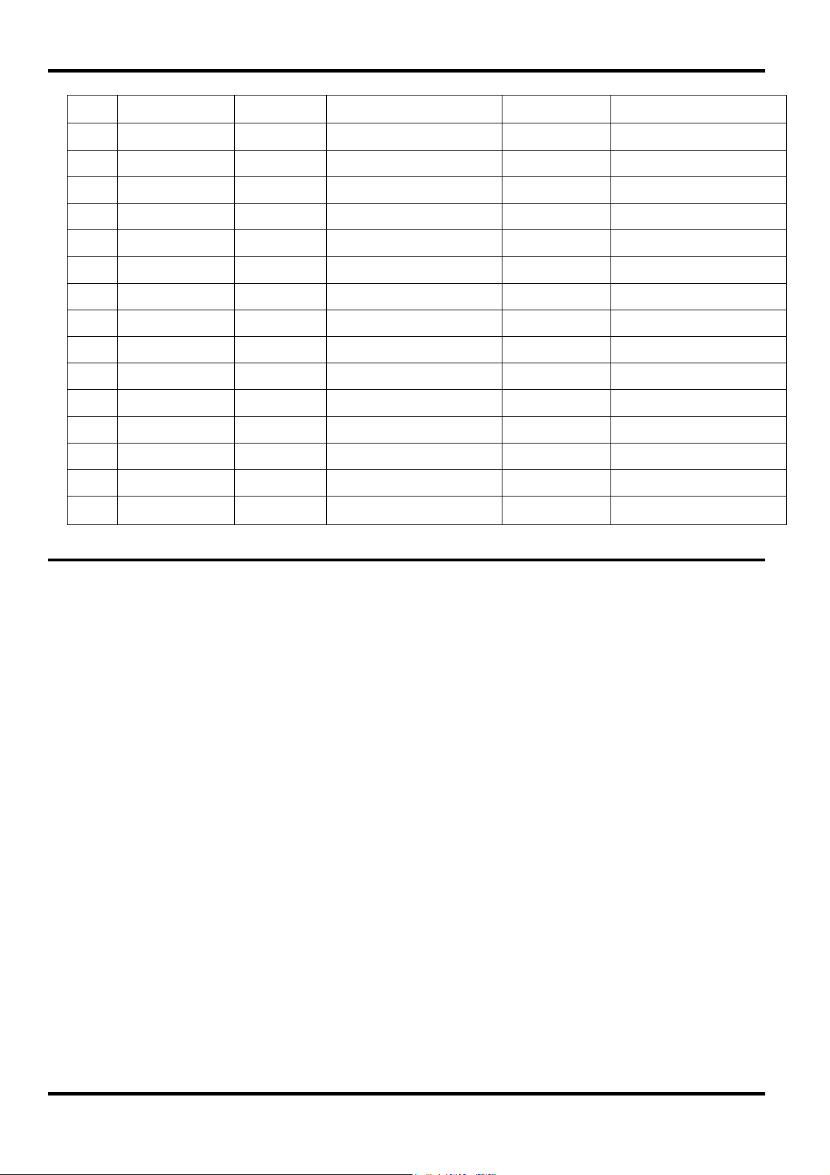
Step Settings Display Adjust for Load Detail
1. O/P off Cal count 0V ± 2mV DVM O/P off volts
2. 0V Cal count 0V ± 2mV DVM V DAC zero
3. Max V, 100mA Cal count 15/30/60V ± 2mV DVM V DAC scale
4. Max V, 100mA O/P volts Display = DVM DVM V metering scale
5. I pot at 0 I pot Display = 0 - I pot ADC zero
6. 2V, 0mA Cal count 0mA ± 0.2mA milli-ammeter High I DAC zero
7. 2V, 0mA O/P amps Display = milli-ammeter milli-ammeter High I metering zero
Change load
8. 2V, max I Cal count 1.5/3A ± 1mA Ammeter High I DAC scale
9. 2V, max I O/P amps Display = ammeter Ammeter High I metering scale
10. 2V, 0mA Cal count 0mA ± 0.02mA milli-ammeter Low I DAC zero
11. 2V, 0mA O/P amps Display = milli-ammeter milli-ammeter Low I metering zero
12. 2V, 500mA Cal count 500mA ± 0.1mA ammeter Low I DAC scale
13. 2V, 500mA O/P amps Display = ammeter ammeter Low I metering scale
14. O/P off ‘End’ - - Stores and exits
Maintenance
The Manufacturers or their agents overseas will provide a repair service for any unit developing a
fault. Where owners wish to undertake their own maintenance work, this should only be done by
skilled personnel in conjunction with the service manual which may be purchased directly from
the Manufacturers or their agents overseas.
Cleaning
If the instrument requires cleaning use a cloth that is only lightly dampened with water or a mild
detergent.
WARNING! TO AVOID ELECTRIC SHOCK, OR DAMAGE TO THE INSTRUMENT, NEVER
ALLOW WATER TO GET INSIDE THE CASE. TO AVOID DAMAGE TO THE CASE NEVER
CLEAN WITH SOLVENTS.
16
Sécurité
Cet instrument est de Classe de sécurité 1 suivant la classification IEC et il a été construit pour
satisfaire aux impératifs EN61010-1 (Impératifs de sécurité pour le matériel électrique en vue de
mesure, commande et utilisation en laboratoire). Il s'agit d'un instrument d'installation Catégorie II
devant être exploité depuis une alimentation monophasée habituelle.
Cet instrument a été soumis à des essais conformément à EN61010-1 et il a été fourni en tout
état de sécurité. Ce manuel d'instructions contient des informations et avertissements qui doivent
être suivis par l'utilisateur afin d'assurer un fonctionnement de toute sécurité et de conserver
l'instrument dans un état de bonne sécurité.
Cet instrument a été conçu pour être utilisé en interne dans un environnement de pollution
Degré 2, plage de températures 5°C à 40°C, 20% - 80% HR (sans condensation). Il peut être
soumis de temps à autre à des températures comprises entre +5°C et –10°C sans dégradation
de sa sécurité. Ne pas l'utiliser lorsqu'il y a de la condensation.
Toute utilisation de cet instrument de manière non spécifiée par ces instructions risque d'affecter
la protection de sécurité conférée. Ne pas utiliser l'instrument à l'extérieur des tensions
d'alimentation nominales ou de la gamme des conditions ambiantes spécifiées.
AVERTISSEMENT! CET INSTRUMENT DOIT ETRE RELIE A LA TERRE
Toute interruption du conducteur de terre secteur à l'intérieur ou à l'extérieur de l'instrument
rendra l'instrument dangereux. Il est absolument interdit d'effectuer une interruption à dessein. Ne
pas utiliser de cordon de prolongation sans conducteur de protection, car ceci annulerait sa
capacité de protection.
Lorsque l'instrument est relié à son alimentation, il est possible que les bornes soient sous
tension et par suite, l'ouverture des couvercles ou la dépose de pièces (à l'exception de celles
auxquelles on peut accéder manuellement) risque de mettre à découvert des pièces sous
tension. Il faut débrancher toute source de tension éventuelle de l'appareil avant de l'ouvrir pour
effectuer des réglages, remplacements, travaux d'entretien ou de réparations. Les condensateurs
qui se trouvent dans le bloc d'alimentation risquent de rester chargés, même si le bloc
d'alimentation a été déconnecté de toutes les sources de tension, mais ils se déchargeront en
toute sécurité environ 1 minute après extinction de l'alimentation.
Eviter dans la mesure du possible d'effectuer des réglages, travaux de réparations ou d'entretien
lorsque l'instrument ouvert est branché à une source d'alimentation, mais si c'est absolument
nécessaire, seul un technicien compétent au courant des risques encourus doit effectuer ce
genre de travaux.
S'il est évident que l'instrument est défectueux, qu'il a été soumis à des dégâts mécaniques, à
une humidité excessive ou à une corrosion chimique, la protection de sécurité sera amoindrie et il
faut retirer l'appareil, afin qu'il ne soit pas utilisé, et le renvoyer en vue de vérifications et de
réparations.
Uniquement remplacer les fusibles par des fusibles d'intensité nominale requise et de type
spécifié. Il est interdit d'utiliser des fusibles bricolés et de court-circuiter des porte-fusibles.
Eviter de mouiller l'instrument lors de son nettoyage.
Les symboles suivants se trouvent sur l'instrument, ainsi que dans ce manuel.
ATTENTION - se référer à la documentation
ci-jointe; toute utilisation incorrecte risque
d'endommager l'appareil.
alimentation secteur OFF (éteinte)
courant alternatif (c.a.)
17
l
Borne de terre (masse)
alimentation secteur ON (allumée)
courant continu (c.c.)
Tension d’alimentation sur secteur
Vérifier que la tension d’alimentation à l’arrière de l’appareil correspond à celle du secteur. S’il
s’avère nécessaire de changer de tension d’alimentation, procéder comme suit :
1. Assurez-vous que l'instrument est déconnecté du secteur.
2. Retirez les rivets-poussoirs en plastique de chaque côté du capot supérieur. Utilisez la lame
d’un petit tournevis pour libérer d'abord la tête du rivet, puis dégager complètement le corps
de la fixation. Retirez les deux vis du panneau arrière qui fixent le capot supérieur ; glissez
le capot vers l'arrière et soulevez-le.
3. Modifiez les connexions du transformateur (des deux transformateurs sur le modèle double)
conformément au schéma ci-dessous :
230V Operation 115V Operation
Installation
4. Remontez l’appareil dans l’ordre inverse. Pour se conformer aux prescriptions des normes
de sécurité, la tension d’alimentation indiquée sur le panneau arrière doit être modifiée pour
indiquer clairement le nouveau réglage de tension.
Fusible
Le fusible CA se trouve dans le compartiment à fusible dans la partie inférieure du connecteur
d'entrée IEC. Pour changer le fusible, retirez le cordon de phase et ouvrez le compartiment à
fusible avec un outil adapté.
Le type de fusible correct mesure 20 x 5 mm avec retardement HBC avec le classement suivant :
Remplacer les fusibles uniquement par des fusibles du courant nominal requis et du type
spécifié. Il est interdit d'utiliser des fusibles bricolés et de court-circuiter les porte-fusibles.
Cordon secteur
Brancher l’appareil sur l’alimentation secteur à l’aide du cordon secteur fourni. S’il s’avère
nécessaire d’utiliser une fiche secteur destinée à un autre type de prise murale, employer un
cordon secteur correctement dimensionné et homologué en l’équipant de la fiche murale voulue
et d’un connecteur IEC60320 C13 du côté de l’appareil. Pour déterminer l’intensité nominale
minimale du cordon en fonction de l’alimentation sur secteur prévue, consulter les
caractéristiques de puissance nominale figurant sur le matériel ou dans le chapitre Spécifications.
BLEU MARRON BLEU MARRON
230V 115V
Simple:
Double: 3,15A (T) 6,3A (T)
1,6 A (T) 3,15A (T)
18
AVERTISSEMENT ! CET APPAREIL DOIT ETRE RELIÉ À LA TERRE.
Toute interruption du conducteur de terre de la prise secteur à l'intérieur ou à l'extérieur de
l’appareil rendra ce dernier dangereux. Il est interdit d'effectuer une coupure intentionnelle.

Montage
Cet appareil convient à la fois à l’utilisation sur établi et au montage en baie. Un kit de montage
en baie pour une baie de 19 pouces est disponible auprès du Fabricant ou de ses agents à
l’étranger
Ventilation
Le module d'alimentation est refroidi par un ventilateur intelligent multi-vitesses qui favorise la
convection verticale. Veillez à ne pas obturer les prises d'air sous l'appareil ni les orifices de
ventilation sur le dessus. En cas de montage en rack, laisser un espace adéquat au-dessus et
au-dessous de l’appareil et/ou utiliser un bloc ventilateur pour un refroidissement forcé.
Toutes les connexions sont effectuées à partir du panneau avant.
La charge devra être connectée aux bornes positive (rouge) et négative (noire) marquées
OUTPUT (sortie). Les deux sont entièrement flottantes et l’une ou l’autre peuvent être
connectées à la masse.
Les connexions de détection à distance sur la charge, si nécessaire, sont réalisées à partir des
bornes positive (+) et négative (−) SENSE (détection). Placez le commutateur LOCAL/DISTANT
sur REMOTE (DISTANT) lorsque la détection distante est requise. Replacez-le sur LOCAL
lorsque la détection à distance n'est pas utilisée.
La borne marquée
.
Connexions
est connectée au châssis et à la borne de mise à la terre.
19

g
Dans ce manuel, les touches du panneau avant, les commandes et les prises sont indiquées en
majuscules, par exemple CURRENT, OUTPUT, LOCK. Les messages affichés sur les voyants
DEL à 7 segments sont affichés dans une police différente, par exemple
trip
. Les fonctions supplémentaires du double instrument en mode quad sont décrites
ensemble à la fin de ce chapitre.
Conditions de mise en marche et de mise sous tension
L’interrupteur d’alimentation (POWER) se trouve en bas à gauche du panneau avant. Lorsque
l'interrupteur d'alimentation est activé (
version du microprogramme avant d'afficher les Volts et Ampères.
A la mise sous tension, le réglage par défaut en usine est desactive. Tous les autres paramètres
seront les mêmes que lors du dernier arrêt de l'appareil.
La répétition de cette opération rétablira le paramètre précédent. Notez que l'état de mise sous
tension des deux sorties du double module doit être réglé individuellement.
L’état de sortie dc à la mise sous tension peut être défini de manière à être
« always off » (toujours désactivé) ou « same as at last power off » (le
même qu'à la dernière mise hors tension). Le paramètre peut être modifié
comme suit. Tout en maintenant enfoncée la touche VIEW (Afficher),
appuyez sur la touche OUTPUT (sortie)
l’écran affiche d’abord le paramètre actuel pendant 1 seconde (
le paramètre par défaut en usine est toujours sélectionné) avant de faire
clignoter le nouveau paramètre pendant 2 secondes (
cas). Au bout de 2 secondes, le nouveau paramètre reste affiché en
permanence à l'écran et le changement est mis en oeuvre ; relâchez les
touches OUTPUT et VIEW.
l ) le mètre de droite indique brièvement le numéro de
Fonctionnement
turn oFF, OtP
et maintenez-la enfoncée ;
OP OFF si
LAST Set dans ce
Contrôle de la sortie
Configuration de la sortie
Une fois l'alimentation activée et la sortie désactivée, la tension de sortie et la limite de
courant peuvent être prédéfinis de manière précises à l'aide des commandes VOLTAGE et
CURRENT ; le lecteur de gauche indique la tension définie, alors que celui de droite affiche le
courant maximum défini et que l'indicateur SETTINGS (paramètres) est allumé.
Lorsque le commutateur de sortie est désactivé, l'indicateur OUTPUT s'allume ; le lecteur de
gauche indique maintenant la tension réelle et celui de droite affiche le courant de charge réel.
Pour changer la plage limite de courant, il faut désactiver la sortie ; si la sortie est activée, le
message d'avertissement
clignote et la plage reste inchangée.
Tension continue
La tension de sortie est ajustée à l'aide des commandes VOLTAGE principale et affinée ; la
commande CURRENT définit le courant maximum qui peut être fourni.
La limite supérieure de la commande CURRENT peut alterner
entre le maximum pour ce modèle et 500 mA avec des
pressions alternatives sur la touche 500 mA RANGE afin
d'affiner le réglage de la limite de courant et de la résolution de
mesure (de 0,1 mA à 500 mA) ; l'indicateur placé à côté de la
touche s'allume lorsque la pla
e 500 mA est sélectionnée.
turn oFF apparaît brièvement à l'écran, l'indicateur OUTPUT
Courant continu
Si la résistance à la charge est suffisamment basse pour qu'à la tension de sortie définie, un
courant supérieur au paramètre limite puisse circuler, le module d'alimentation passe
20

A
automatiquement en fonctionnement de courant continu. La sortie de courant est ajustée par la
commande CURRENT et les commandes VOLTAGE permettent de régler la tension maximale
pouvant être générée.
L'indicateur CC s'allume pour indiquer le mode de courant continu.
Sortie d’intensité instantanée
La commande de limite d’intensité peut être réglée pour limiter l’intensité de sortie continue à des
niveaux descendant jusqu’à 1mA (0,1 mA sur une plage de 500 mA). Cependant, communément
à tous les générateurs de précision d’établi, un condensateur est connecté sur la sortie pour
conserver la stabilité et une bonne réponse aux défauts transitoires. Ce condensateur se charge
sur la tension de sortie et le chargement de la sortie produira une impulsion d’intensité à la
décharge du condensateur, ce qui ne dépend pas du réglage de limite d’intensité.
Moyenne actuelle du mètre
Appuyez de nouveau sur la touche pour CANCEL (annuler) la moyenne du mètre et revenir à la
constante de temps standard de 20 ms.
Pour réduire les sautillements avec des courants de charge
variant rapidement, il est possible de sélectionner une constante
d'une durée de 2 secondes en appuyant sur la touche METER
VERAGE ; l'indicateur situé à côté de la touche s'allume lorsque
la moyenne du mètre est sélectionnée.
Économie
Le module d'alimentation minimise la dissipation en utilisant une pré-régulation électronique afin
de conserver une tension maximale faible pour les condensateurs de sortie. En outre, pour
optimiser le fonctionnement à des niveaux extrêmes de tension d'entrée et de puissance de
sortie CC, le transformateur secondaire est intelligemment remplacé par un relais. L'hystérésis
est utilisée au point de seuil pour empêcher un basculement inutile lorsque la sortie est définie à
ce niveau environ. En dehors d'un « clic audible », l'utilisateur ignorera que le relais s'est activé ;
cela ne perturbera pas la sortie.
Connexion à la charge
La charge devra être connectée aux bornes OUTPUT positive (rouge) et négative (noire). Les
deux sont entièrement flottantes et l’une ou l’autre peuvent être connectées à la masse.
Détection à distance
L'unité possède une impédance de sortie très faible, mais elle est inévitablement augmentée par
la résistance des fils de connexion. A hautes intensités, ceci peut se traduire par des différences
significatives entre la tension source indiquée et la tension réelle de la charge (deux fils de
raccordement de 2mΩ chuteront de 0,2V à 5 Ampères, par exemple).
Pour éviter les problèmes d'instabilité et de réponse transitoire, il convient d'assurer un bon
couplage entre chaque fil de sortie et de détection. Pour ce faire, on peut torsader les fils
ensemble ou utiliser des câbles à protection coaxiale (détection par le fil interne). Un
condensateur électrolytique placé directement sur le point de connexion de la charge peut
également s’avérer avantageux.
La chute de tension dans chaque fil de sortie ne doit pas dépasser 0,5 Volts.
Replacez le commutateur LOCAL/REMOTE sur LOCAL lorsque la détection à distance n'est pas
utilisée.
Ce problème peut être minimisé en utilisant des fils de
raccordement courts et épais, mais lorsque cela s’avère
nécessaire, on peut le surmonter complètement en utilisant la
fonction de détection à distance. Ceci nécessite de connecter
les bornes de détection à la sortie sur la charge plutôt que sur
la source ; insérer les fils dans les bornes à ressort SENSE
(détection) et les connecter directement à la charge. Basculez
le commutateur LOCAL/REMOTE sur REMOTE.
21

Connexion en Série ou en Parallèle avec d’Autres Sorties
Les sorties du générateur sont entièrement flottantes et peuvent être utilisées en série avec
d’autres générateurs pour produire des tensions hautes CC allant jusqu’à 300 V CC.
La tension maximale admise entre toute borne et la terre (
AVERTISSEMENT ! De telles tensions sont excessivement dangereuses et un grand soin devra
être apporté à la protection des bornes pour une telle utilisation. En aucun cas on ne devra
toucher les bornes de sortie lorsque le générateur est allumé pour une telle utilisation. Tous les
branchements aux bornes doivent être établis avec tous les appareils hors tension.
Il convient de noter que le générateur ne peut que produire du courant et non en absorber, ainsi
les générateurs ne peuvent être connectés en série en anti-phase.
L’appareil peut être connecté en parallèle avec d’autres pour produire des courants plus forts.
Lorsque plusieurs appareils sont connectés en parallèle, la tension de sortie sera égale à celle du
générateur ayant le plus grand réglage de sortie, jusqu’à ce que le courant consommé dépasse
son réglage de limite d’intensité, moment auquel la sortie tombera au réglage le plus élevé
suivant, et ainsi de suite. En mode d’intensité constante, les appareils peuvent être connectés en
parallèle pour fournir une intensité égale à la somme des réglages de limite d’intensité.
Protection
La sortie dispose d'une protection intrinsèque contre les court-circuits et est protégée contre les
tensions inverses par une diode ; le courant continu inverse ne doit pas dépasser 3 ampères,
même si les pointes transitoires peuvent être nettement plus élevées. Si la tension inverse
appliquée peut produire plus de courant que la limite définie et que la sortie est activée, la sortie
passera au niveau limite du courant (l'indicateur CC clignotera) et son affichage présentera la
tension inverse sur la diode de protection ; si la sortie est désactivée, seul l'indicateur CC
clignotera.
Comme tous les modules d'alimentation à terminaison unique et régulés en série, l'unité ne peut
pas collecter le courant provenant d'une source externe. Si une tension supérieure à la tension
de sortie définie de l'unité est appliquée à partir d'une source externe, le régulateur interne se
désactivera et aucun courant ne circulera ; si la sortie est activée, le lecteur de tension lira la
tension appliquée. Cela ne produira aucun dommage à condition que la tension appliquée ne
dépasse pas la tension de sortie maximale du module d'alimentation de plus de 20 Volts.
La sortie (OUTPUT) étant désactivée, la charge reste connectée à la phase de sortie du module
d'alimentation ; la tension de sortie est simplement définie sur zéro. Ne pas appliquer aux bornes
du module d'alimentation de tensions externes dépassant de plus de 20 V la tension de sortie
nominale, même lorsque la sortie est désactivée, car cela pourrait endommager l'appareil.
) est de 300 VCC
Protection contre les dépassements de température
Un capteur interne détecte les dépassements de température liés à une obturation du flux d'air,
une défaillance du ventilateur ou une autre défaillance d'un circuit. Un dépassement de
température désactive la sortie, l'indicateur OUTPUT clignote et l'écran affiche le message
OtP triP. Une fois que la cause du dépassement de température a été éliminée et que
l'instrument est refroidi, l'indicateur de sortie s'éteint, mais le message OtP triP reste présent.
Une pression sur la touche OUTPUT modifie l'affichage et indique la tension et le courant
prédéfinis (l'indicateur SETTINGS s'allume), mais la sortie reste désactivée ; une deuxième
pression active normalement la sortie.
En cas de pression sur la touche OUTPUT pendant que l'instrument est toujours en dépassement
de température (l'indicateur OUTPUT clignote), le message OtP triP est remplacé par la
tension et le courant prédéfinis (l'indicateur SETTINGS s'allume), mais la sortie reste désactivée ;
chaque pression suivante sur la touche OUTPUT fait apparaître brièvement le message OtP
triP mais la sortie reste désactivée jusqu'à ce que la condition de dépassement de
température soit terminée.
22

p
g
Affichage des paramètres
Verrouillage des paramètres
Une pression sur la touche LOCK verrouille numériquement la limite de tension et de courant
définie. Les paramètres sont stockés avec une précision supérieure à 1 chiffre. Les ajustements
suivants des commandes VOLTAGE et CURRENT seront sans effet.
Comme l'annulation de LOCK provoque un changement des paramètres de sortie si la position
des commandes VOLTAGE et CURRENT a été modifiée, des rappels d’avertissement sont
donnés avant l’annulation du LOCK.
Appuyer et maintenir la touche enfoncée pour annuler LOCK.
Si la sortie est désactivée (l’état sûr), l’écran fait clignoter les paramètres « non verrouillés » deux
fois avant l'application du changement ; l’indicateur LOCK s'éteint.
Le relâchement de la touche LOCK à tout moment pendant que l'écran clignote interrompra
l’annulation du LOCK.
Une tentative de changement de la plage limite de courant (voir la section Configuration de la
Sortie) ou des limites extrêmes de la tension (voir la section Ecart de tension) avec LOCK activé
n'est pas admise ; si une telle tentative est faite, le message Unloc apparaît brièvement et
l'indicateur LOCK clignote également. Si la sortie est également activée lorsque ces actions sont
tentées, le message turn oFF apparaît en premier lieu à l'écran (accompagné de l'indicateur de
sortie qui clignote), suivi du message Unloc (avec l'indicateur LOCK clignotant).
Les limites de tension et de courant définies sont toujours affichées
lorsque la sortie est désactivée, mais peuvent aussi être lues après
une pression sur la touche VIEW ; l'indicateur SETTINGS s'allume
en cas de
ression sur la touche VIEW.
Si la sortie est toujours activée, le message OP on (sortie
activée) clignote deux fois à l'écran, suivi par le clignotement
des nouveaux paramètres « non verrouillés » pendant 2 à 3
secondes (un clignotement lent, puis plus rapide), avant que le
changement ne soit finalement appliqué, l'indicateur LOCK
s'éteint une fois le chan
emlent effectué.
Utilisation de l'écart de tension
La fonction VOLTAGE SPAN (V-Span) (écart de tension) permet à l'utilisateur de redéfinir les
valeurs d'extrémité des commandes VOLTAGE de telle manière que les commandes fonctionnent
dans une plage de tension spécifique, plus étroite. Cela présente non seulement l'avantage de se
protéger contre l'application accidentelle de la charge des tensions en dehors de la plage, mais
fournit également un contrôle analogique haute résolution sur la plage de tension spécifiée en
utilisant l'intégralité de la rotation à 300 ° des commandes de tension.
Dans la mesure où l'activation de V-Span modifiera toujours la tension de sortie, cette option ne
peut être activée ou annulée que si la sortie est désactivée ; toute tentative d'activation ou
d’annulation de V-Span alors que la sortie est affichée provoque l'apparition rapide du message
turn oFF invitant l'utilisateur à désactiver la sortie.
Pour définir de nouvelles valeurs pour V
(annulée).
La limite inférieure de tension est définie à l'aide des commandes MAIN et FINE VOLTAGE qui
permettent de choisir exactement la valeur requise ; la touche V
V-Span est activé ou désactivé à l’aide de la touche
ENABLE. L’indicateur ENABLE est allumé lorsque
V-Span est sélectionné. La valeur d'usine par défaut est
V
= 3V, V
min
ou V
min
max
= 5V
max
la fonction V-Span doit être désactivée
est alors maintenue enfoncée
min
23

jusqu'à ce que l'affichage de gauche (V) cesse de clignoter et que l'affichage de droite (mA)
indique Set. Le paramètre peut être affiché à tout moment par une brève pression (<1 seconde)
sur la touche V
manière à l'aide des commandesVOLTAGE et de la touche V
. La limite de tension supérieure est définie et affichée exactement de la même
min
.
max
Les limites peuvent être réglées dans n'importe quel ordre et sur n'importe quelle valeur située
dans la plage de sortie de l'instrument, mais V-Span peut uniquement être activé à l'aide de la
touche ENABLE si V
max
≥ (V
+ 0,1V) ; si cette condition n'est pas remplie, le message Set
min
Err apparaît brièvement et la fonction V-Span n'est pas mise en œuvre.
Lorsque V-Span est activé, la plage de la commande MAIN VOLTAGE est exactement de V
V
quand la commande FINE est réglée à son point intermédiaire, marqué sur le panneau par
max
un • . La commande FINE elle-même peut être utilisée pour régler plus précisément la valeur sur
±1% (de l'écart de tension).
Mode Control (Controle de mode) du Quad-Mode Dual
Toutefois, on ne peut pas garantir qu'il n'y aura jamais de courants transitoires indésirables lors
du changement de mode, et il est donc recommandé que les deux sorties soient toujours
désactivées avant tout changement de mode.
Independent
Définissez le MODE sur INDEPENDENT. Les deux sorties sont alors entièrement indépendantes
et isolées électriquement, chacune pouvant être définie comme décrit dans la section
précédente, Contrôle de sortie.
Les quatre modes de fonctionnement du Quad-Mode Dual sont
décrits ci-dessous ; on modifie ce mode à l’aide de la molette
MODE. Pour éviter l’application accidentelle de tensions
imprévues aux circuits connectés aux sorties, le changement
de mode provoque toujours une désactivation des deux sorties.
min
à
Il n’est pas possible de basculer du mode Independent au mode Tracking avec LOCK défini sur la
sortie Slave. Le message Un loc apparaît dans l’écran Slave et la fonction LOCK doit être
désactivée (en mode Independent) avant que les modes Tracking puissent être utilisés.
Voir aussi le paragraphe Paramètres Slave conservés.
Isolated Tracking
Définissez le MODE sur ISOLATED TRACKING. Les deux sorties restent isolées électriquement,
mais les contrôles de Voltage de la sortie Master présentent une tension identique sur la sortie
Slave. Les commandes Current du Slave restent indépendant, notamment la plage 500 mA et les
fonctions Meter Average.
L’isolation électrique permet aux deux sorties d’être connectés afin de fournir, par exemple, les
tensions de sortie de polarité opposée ou des tensions identiques connectées à différentes
références du système (par ex. la prise de terre numérique et la prise de terre analogique).
Les fonctions LOCK et VOLTAGE SPAN du Master fonctionnent exactement comme décrit
précédemment et, comme la tension de sortie du Slave suit celle du Master, elles contrôlent
également la fonction de sortie Slave. Notez que seule la tension de sortie du Slave est
verrouillée lorsque le LOCK Master est utilisé ; les commandes de courant du Slave, y compris
les fonctions 500mA Range et Meter Average, restent indépendantes.
La touche LOCK de la sortie Slave est ignorée et si on l’utilise, elle fait apparaître temporairement
le message In trac sur l’écran Slave à titre de rappel.
24

)
Il est possible de basculer du mode Tracking au mode Independent alors que le LOCK est
toujours activé sur le Master. Les paramètres Master (sortie de droite) restent « verrouillés » mais
les paramètres de la sortie de gauche ne sont pas verrouillés.
Les touches Voltage Span du Slave ont une fonction différente en mode Tracking, voir la section
suivante.
Isolated Ratio (%) Tracking
Définissez le MODE sur ISOLATED TRACKING.
L’instrument fonctionne comme décrit ci-dessus pour le mode Tracking mais la tension du Slave
peut être définie sur un pourcentage (de 0 % à 101 %) de la tension Master à l’aide des
commandes Slave Voltage. Le ratio est ensuite maintenu lorsque la tension du Master varie.
Une nouvelle pression sur la touche ENABLE ramène le Slave au mode Tracking standard
(indicateur ENABLE éteint).
Le Ratio Tracking ne peut être activé ou désactivé que lorsque la sortie est désactivée. Si la
sortie est activée, l'écran affiche brièvement le message turn oFF lorsque vous appuyez sur
ENABLE et le changement n’est pas appliqué.
Le Ratio Tracking est activé par une pression
sur la touche ENABLE dans la section
VOLTAGE SPAN du Slave (indicateur
ENABLE activé
Chaque fois que le mode Ratio Tracking est activé, l’écran Slave affiche temporairement Pcnt
on avant d'afficher à nouveau la tension de sortie qui est maintenant définie.
La valeur de pourcentage peut être affichée à tout moment en appuyant sur la touche V
V
Slave affiche le paramètre de pourcentage sous la forme 90.0 Pcnt et les contrôles Slave
Voltage permettent de définir le pourcentage de ratio requis. Le pourcentage de ratio peut être
défini avant l’activation de Ratio Tracking (indicateur ENABLE éteint).
Les fonctions LOCK et VOLTAGE SPAN du Master fonctionnent exactement comme décrit
précédemment. Toutefois, lorsque Ratio Tracking est activé, les commandes de Slave Voltage
peuvent toujours être utilisées pour régler le pourcentage de ratio de la tension du Slave, même
si la tension du Master est verrouillée.
Voir aussi le paragraphe Paramètres du Slave conservés.
Parallel
L’interrupteur MODE est défini sur PARALLEL. L’instrument fonctionne véritablement en mode
parallèle, avec toute la puissance disponible à partir de la sortie Master qui peut ensuite fournir
jusqu’à 6 ampères. La sortie Slave est désactivée et ses écrans sont éteints.
En mode Parallel, la valeur de la limite actuelle est doublée pour le même paramètre de contrôle
de limite Current, y compris la plage 500 mA, qui devient 1000 mA au maximum ; à titre
d'avertissement, la première fois que le mode Parallel est sélectionné, l'écran actuel clignote
deux fois avant d'afficher en continu la nouvelle limite. De même, le courant s'affiche deux fois
lorsque le mode bascule de Parallel à Tracking, pour vous avertir du fait que la limite de courant
de sortie du Master est maintenant réduite de moitié.
Les fonctions LOCK et VOLTAGE SPAN du Master opèrent exactement comme décrit
précédemment. Il est possible de basculer du mode Parallel au mode Tracking (et vice versa)
alors que LOCK est toujours réglé sur le Master ; les commandes Voltage et Current du Master
restent en LOCK, comme décrit précédemment. Toutefois, la limite de courant réelle définie du
Master doublera encore (en passant du mode Tracking au mode Parallel), ou sera réduite de
moitié (en passant du mode Parallel au mode Tracking), même si LOCK est défini, mais
l'affichage du courant clignote pour vous avertir de ce changement.
min
de la sortie Slave. Lorsque vous maintenez l’une de ces deux touches enfoncées, l'écran du
max
ou
25

Paramètres du Slave conservés
Si V-Span est activé sur la sortie Slave en mode INDEPENDENT, il est désactivé lorsque le mode
TRACKING estsélectionné, mais réactivé ,lorsque le mode INDEPENDENT est à nouveau
sélectionné.
Si Ratio (%) Tracking est activé sur la sortie Slave en mode TRACKING, il est désactivé lorsque
INDEPENDENT ou PARALLEL est sélectionné, mais réactivé lorsque le mode TRACKING est à
nouveau sélectionné.
Commande Marche/Arrêt de la sortie simultanée
Les touches Both On / Both Off s’ajoutent aux interrupteurs OUTPUT
individuels et permettent d’activer ou de désactiver les deux sorties de
manière synchronisée d’une simple pression.
Le Constructeur ou ses agents à l'étranger répareront tout bloc qui tombe en panne. Si le
propriétaire de l'appareil décide d'effectuer ses propres réparations, ceci doit uniquement être
effectué par un personnel spécialisé qui doit se référer au manuel de révisions que l'on peut se
procurer directement auprès du Constructeur ou de ses agents à l'étranger.
Nettoyage
S'il faut nettoyer le bloc d'alimentation, utiliser un chiffon légèrement imbibé d'eau ou d'un
détergent doux. Nettoyer le cadran d'affichage au moyen d'un chiffon sec et doux.
AVERTISSEMENT! EMPECHER TOUTE INTRODUCTION D'EAU DANS LE BOITIER AFIN
D'EVITER TOUT CHOC ELECTRIQUE ET DEGATS AU BLOC D'ALIMENTATION. NE JAMAIS
UTILISER DE DISSOLVANTS POUR NETTOYER LE BLOC, AFIN D'EVITER
D'ENDOMMAGER LE BOITIER OU LE CADRAN D'AFFICHAGE.
Les touches Both On / Both Off fonctionnent dans les quatre modes de
configuration.
Entretien
26

Sicherheit
Dieses Gerät wurde nach der Sicherheitsklasse (Schutzart) I der IEC-Klassifikation und gemäß
den europäischen Vorschriften EN61010-1 (Sicherheitsvorschriften für elektrische Mess-,
Steuer-, Regel- und Laboranlagen) entwickelt. Es handelt sich um ein Gerät der
Installationskategorie II, das für den Betrieb von einer normalen einphasigen Versorgung
vorgesehen ist.
Das Gerät wurde gemäß den Vorschriften EN61010-1 geprüft und wurde in sicherem Zustand
geliefert. Die vorliegende Anleitung enthält vom Benutzer zu beachtende Informationen und
Warnungen, die den sicheren Betrieb und den sicheren Zustand des Gerätes gewährleisten.
Dieses Gerät ist für den Betrieb in Innenräumen der Umgebungsklasse 2 , für einen
Temperaturbereich von +5° C bis +40° C und 20 - 80 % relative Feuchtigkeit (nicht
kondensierend) vorgesehen. Gelegentlich kann es Temperaturen zwischen –10°C und +5°C
ausgesetzt sein, ohne dass seine Sicherheit dadurch beeinträchtigt wird. Betreiben Sie das Gerät
jedoch auf keinen Fall, solange Kondensation vorhanden ist.
Ein Einsatz dieses Gerätes in einer Weise, die für diese Anlage nicht vorgesehen ist, kann die
vorgesehene Sicherheit beeinträchtigen. Auf keinen Fall das Gerät außerhalb der angegebenen
Nennversorgungsspannungen oder Umgebungsbedingungen betreiben.
WARNUNG! - DIESES GERÄT MUSS GEERDET WERDEN!
Jede Unterbrechung des Netzschutzleiters innerhalb oder außerhalb des Gerätes macht das
Gerät gefährlich. Eine absichtliche Unterbrechung ist verboten. Die Schutzwirkung darf durch
Verwendung eines Verlängerungskabels ohne Schutzleiter nicht aufgehoben werden.
Ist das Gerät an die elektrische Versorgung angeschlossen, so können die Klemmen unter
Spannung stehen, was bedeutet, daß beim Entfernen von Verkleidungs- oder sonstigen Teilen
(mit Ausnahme der Teile, zu denen Zugang mit der Hand möglich ist) höchstwahrscheinlich
spannungsführende Teile bloßgelegt weden. Vor jeglichem Öffnen des Geräts zu Nachstell-,
Auswechsel-, Wartungs- oder Reparaturzwecken, dieses stets von sämtlichen Spannungsquellen
abklemmen. Kondensatoren in der Stromversorgung können auch noch nach Abschalten
sämtlicher Stromversorgung Spannung führen, sie entladen sich jedoch innerhalb von etwa einer
Minute nach Spannungsabschaltung.
Jegliche Nachstellung, Wartung und Reparatur am geöffneten, unter Spannung stehenden Gerät,
ist nach Möglichkeit zu vermeiden. Falls unvermeidlich, sollten solche Arbeiten nur von
qualifiziertem Personal ausgeführt werden, das sich der Gefahren bewusst ist.
Ist das Gerät eindeutig fehlerbehaftet, bzw. wurde es mechanisch beschädigt, übermäßiger
Feuchtigkeit oder chemischer Korrosion ausgesetzt, so können die Schutzeinrichtungen
beeinträchtigt sein, weshalb das Gerät aus dem Verkehr zurückgezogen und zur Überprüfung
und Reparatur eingesandt werden sollte.
Sicherstellen, daß nur Sicherungen der vorgeschriebenen Stromstärke und des vorgesehenen
Typs als Ersatz verwendet werden. Provisorische “Sicherungen” und der Kurzschluss von
Sicherungshaltern ist verboten. Beim Reinigen darauf achten, dass das Gerät nicht nass wird.
Am Gerät werden folgende Symbole verwendet:
Vorsicht! Bitte beachten Sie die beigefügten Unterlagen.
Falsche Bedienung kann Schaden am Gerät verursachen!
Erdungsklemme
Netz OFF (aus)
l
27
Netz ON (ein)
Wechselstrom
Gleichstrom

Netzbetriebsspannung
Prüfen Sie, dass die an der Geräterückplatte angezeigte Netzspannung Ihrem lokalen Netz
entspricht. Sollte es erforderlich sein, die Betriebsspannung zu ändern, gehen Sie wie folgt vor:
1. Stellen Sie sicher, dass das Gerät von der Netzstromversorgung getrennt ist.
2. Entfernen Sie die Plastikdrucknieten an allen Seitenkanten des Deckels. Nehmen Sie einen
kleinen Schraubendreher zur Hand, um zuerst den Nietkopf und danach die gesamte Niethülse
herauszuhebeln. Entfernen Sie die beiden Schrauben auf der Rückwand zur Befestigung des
Deckels - schieben Sie dann den Deckel nach hinten und nehmen Sie ihn ab.
3. Ändern Sie die Transformatoranschlüsse (beider Trafos im Falle des Doppelnetzgeräts) nach
folgender Zeichnung:
Installation
230 V Betrieb 115 V Betrieb
4. Die Wiedermontage erfolgt in umgekehrter Reihenfolge zum Ausbau. Um den
Sicherung
Die Wechselstromsicherung befindet sich im Sicherungsfach im unteren Teil des IEC
Netzsteckers. Zum Wechseln der Sicherung das Netzkabel abziehen und das Sicherungsfach mit
einem geeigneten Hilfsmittel öffnen.
Verwenden Sie eine Sicherung vom Typ 20 x 5 mm 250V HBC, träge, mit folgenden Werten:
Sicherstellen, dass nur Sicherungen des vorgeschriebenen Stromwerts und des vorgesehenen
Typs als Ersatz verwendet werden. Provisorische „Sicherungen“ und das Überbrücken von
Sicherungshaltern sind verboten!
Netzkabel
BLAU BRAUN BLAU BRAUN
Sicherheitsvorschriften zu entsprechen, muss die auf der Rückwand angegebene
Betriebsspannung so geändert werden, dass die neue Einstellung der Betriebsspannung
deutlich zu erkennen ist.
230V 115V
Einfach: 1,6A (T) 3,15A (T)
Doppel: 3,15A (T) 6,3A (T)
28
Schließen Sie das Gerät unter Verwendung des mitgelieferten Netzkabels an die
Wechselspannungsversorgung an. Falls ein Netzstecker für eine unterschiedliche Netzsteckdose
erforderlich ist, muss ein geeigneter und zugelassener Netzkabelsatz verwendet werden, der mit
dem geeigneten Wandstecker und einem IEC60320 C13-Stecker für das Geräteende versehen
ist. Zur Bestimmung der Mindest-Nennstromstärke des Kabelsatzes für die beabsichtigte
Wechselspannungsversorgung sind die Informationen zu Leistungswerten auf dem Gerät bzw. in
seiner Spezifikation hinzuzuziehen.
ACHTUNG! DIESES GERÄT MUSS GEERDET SEIN.
Jegliche Unterbrechung der Netzerde, ob im Innern oder außerhalb des Geräts, macht das Gerät
zur Gefahrenquelle! Eine absichtliche Unterbrechung ist verboten!

Befestigung
Dieses Gerät kann auf einer Arbeitsplatte oder in einem Gestell befestigt werden. Ein RackMontagesatz für ein 19”-Rack ist vom Hersteller oder einem Fachhändler erhältlich.
Belüftung
Das Gerät wird mittels intelligenter Gebläse mit stufenweiser Drehzahlregelung gekühlt, um so
die Vertikalkonvektion zu unterstützen. Es muss sichergestellt werden, dass die Luftein- und auslässe auf der Unter- und Oberseite des Geräts nicht blockiert werden. Bei Geräten, die im
Rack montiert sind, muss genügend Raum um das Gerät gelassen werden und/oder eine
Zwangskühlung mittels eines zusätzlichen Ventilators eingesetzt werden.
Alle Anschlüsse erfolgen auf der Gerätevorderseite.
Die Last sollte an die mit OUTPUT (Ausgang) gekennzeichneten positiven (roten) und negativen
(schwarzen) Klemmen angelegt werden. Beide Klemmen sind galvanisch getrennt und können
daher an Erde gelegt werden.
Die Fernfühleranschlüsse für die Last (falls gewünscht) erfolgen über die entsprechenden Plus(+) und Minus (-) SENSE Klemmen. Setzen Sie den Schalter LOCAL/REMOTE auf REMOTE
wenn die Fernfühlerfunktion eingesetzt werden soll. Setzen Sie den Schalter auf LOCAL zurück,
wenn die Fernfühlerfunktion nicht verwendet wird.
Die mit
Anschlüsse
markierte Klemme ist mit dem Gehäuse und dem Schutzleiter verbunden.
29

In diesem Handbuch sind die Tasten, Steuerelemente und Buchsen auf der Frontplatte in
Großbuchstaben dargestellt, z. B. CURRENT, OUTPUT und LOCK. Meldungen auf den 7Segment LEDs werden in einer anderen Schriftart angegeben, z. B.:
Einschalten und Einschaltzustand
Der Netzschalter befindet sich unten links auf der Gerätevorderseite. Nach dem Betätigen des
Netzschalters (
der Spannungs- und Stromanzeige.
Beim Einschalten ist das Gerät vom Werk aus so eingerichtet, dass der Ausgang abgeschaltet ist.
Alle anderen Einstellungen entsprechen dem Zustand vor dem letzten Abschalten des Geräts.
l ) wird auf der rechten Anzeige kurz die Firmware-Version angezeigt, gefolgt von
Bedienung
turn oFF, OtP trip.
Wenn Sie diesen Vorgang wiederholen wird die Einstellung wieder rückgängig gemacht.
Beachten Sie, dass der Einschaltzustand des Doppelnetzgeräts für jeden Ausgang einzeln
eingerichtet werden muss.
Der Gleichspannungsausgang kann so eingerichtet werden, dass er beim
Einschalten des Geräts entweder immer ausgeschaltet ist oder den Zustand
vor dem letzten Ausschalten des Geräts annimmt. Diese Einstellung kann wie
folgt geändert werden: Bei gedrückter VIEW Taste, die Taste
drücken und halten – auf dem Display erscheint nun 1 Sekunde lang die
aktuelle Einstellung (
Anschließend zeigt das Display 2 Sekunden lang blinkend die neue
Einstellung an (
Einstellung kontinuierlich angezeigt und die Änderung durchgeführt. Geben
Sie nun die Tasten OUTPUT und VIEW frei.
Ausgangsregelung
Einrichten des Ausgangs
Bei eingeschalteter Stromversorgung und ausgeschaltetem OUTPUT (Ausgang) können Sie
die Spannungs- und Strombegrenzung mit den Reglern VOLTAGE und CURRENT präzise regeln.
Die linke Anzeige zeigt die eingestellte Spannung und die rechte Anzeige den maximalen Strom
an - die SETTINGS Anzeige leuchtet auf.
Bei eingeschaltetem Ausgang leuchtet die OUTPUT Anzeige auf – das linke Messinstrument
zeigt jetzt die tatsächliche Spannung und das rechte Messinstrument den aktuellen Laststrom.
OUTPUT
OP OFF falls die Werksvoreinstellung gewählt ist).
LASt Set in diesem Fall). Nach 2 Sekunden wird die neue
Die Anzeige neben der Taste leuchtet auf, wenn der 500 mA Bereich gewählt ist. Um den
Strombegrenzungsbereich ändern zu können, muss der Ausgang abgeschaltet werden - sollte
der Ausgang noch eingeschaltet sein, erscheint kurz die Meldung
OUTPUT Anzeige blinkt und der Bereich bleibt unverändert.
Konstantspannung
Die Ausgangsspannung wird mit den VOLTAGE Grob- und Feinreglern geregelt; mit dem Regler
CURRENT wird der Maximalstrom eingestellt.
Konstantstrom
Wenn der Lastwiderstand so niedrig ist, dass bei der gewählten Ausgangsspannung ein höherer
Strom fließen würde, als durch die Strombegrenzung vorgegeben, so schaltet das Netzgerät
automatisch auf Konstantstrombetrieb. Der Ausgangsstrom wird mit dem CURRENT Regler
eingestellt, während die VOLTAGE Regler die maximal erzeugte Spannung bestimmen.
Die Konstantstromanzeige (CC) leuchtet auf, um den Betrieb mit Konstantstrom anzuzeigen.
30
Der obere Grenzwert für den CURRENT Regler kann durch
abwechselndes Drücken der RANGE Taste zwischen dem
Maximalwert für dieses Gerät und 500 mA umgeschaltet werden, um
so eine Feineinstellung der Strombegrenzung und der Messauflösung
(0,1 mA bis zu 500 mA) zu erreichen.
turn oFF im Display, die

Momentanstrom
Mit Hilfe der Strombegrenzungsfunktion kann der Dauerausgangsstrom bis auf 1 mA herab
begrenzt werden (0,1 mA im 500 mA Bereich). Wie bei allen Präzisionsnetzgeräten wird jedoch
auch hier ein Kondensator am Ausgang parallel geschaltet, um eine stabile Ausgangsspannung
und ein gutes dynamisches Verhalten zu gewährleisten. Dieser Kondensator lädt sich bis zur
Höhe der Ausgangsspannung auf und erzeugt beim Anschließen einer Ausgangslast durch seine
Entladung einen Stromimpuls, auf den die Strombegrenzung keinen Einfluss hat.
Mittelwerte der Stromstärkemessung
Um die Messschwankungen bei veränderlichen Lasten zu
reduzieren, kann durch Drücken auf die Taste METER AVERAGE
eine Zeitkonstante von 2 Sekunden gewählt werden – ist diese
Funktion aktiviert, so leuchtet eine Anzeige neben der Taste auf.
Drücken Sie die Taste erneut, um diese Mittelung zu annullieren und
zur Standardzeitkonstante von 20 ms zurückzukehren.
Wirkungsgrad
Das Netzgerät reduziert Leistungsverluste durch elektronische Vorregelung, um eine niedrige
Gesamtspannung an den Leistungsreglern zu erhalten. Darüber hinaus wird die Trafoanzapfung
über ein Relais intelligent geregelt, um den Betrieb bei extremer Netzeingangsspannung bzw. DC
Ausgangsleistung zu optimieren. Am Schwellenwert wird eine Hysteresefunktion eingesetzt, um
unnötiges Schalten in Nähe dieses Werts zu verhindern. Von einem kaum hörbaren „Klick”
abgesehen, ist das Schalten des Relais unmerklich – am Ausgang ist keine Störung bemerkbar.
Anschluss der Last
Die Last sollte an die mit OUTPUT gekennzeichneten positiven (rot) und negativen (schwarz)
Klemmen angelegt werden. Beide Klemmen sind galvanisch getrennt und können daher an Erde
gelegt werden.
Fernfühlerfunktion
Obwohl das Gerät eine sehr geringe Ausgangsimpedanz besitzt, erhöht sich diese zwangsweise
durch den Widerstand der angeschlossenen Kabel. Bei hohen Strömen ergibt sich hieraus ein
deutlicher Unterschied zwischen der angezeigten Quellspannung und der tatsächlichen
Lastspannung (zwei Anschlusskabel mit 20 mΩ erzeugen z. B. bei einem Strom von 5 A einen
Spannungsabfall von 0,2 V).
Um Instabilität und dynamisches Fehlverhalten zu vermeiden muss darauf geachtet werden, dass
eine gute Verbindung zwischen jedem Ausgangs- und Fernfühlerkabel besteht. Dies wird erreicht,
indem man entweder die Kabel miteinander verdrillt oder ein abgeschirmtes Koaxialkabel
verwendet (die Fernfühlerleitung bildet hierbei den Innenleiter). Auch ein zum Lastanschluss
parallel geschalteter Elektrolytkondensator kann hilfreich sein.
Dieses Problem lässt sich zwar durch Verwendung kurzer
Anschlusskabel mit großem Querschnitt einschränken, es ist
aber besser, diesen Effekt mit Hilfe der Fernfühlerfunktion
ganz zu umgehen. Dazu müssen die Fernfühlerklemmen
(Sense) an der Last anstelle der Spannungsquelle
angeschlossen werden. Schließen Sie die Kabel an die
Federklemmen des SENSE-Anschlusses und direkt an der
Last an. Setzen Sie den Schalter LOCAL/REMOTE auf
REMOTE.
Der Spannungsabfall des jeweiligen Ausgangskabels darf 0,5 Volt nicht überschreiten.
Setzen Sie den LOCAL/REMOTE Schalter auf LOCAL zurück, wenn die Fernfühlerfunktion nicht
verwendet wird.
31

Serielle oder Parallelschaltung mit anderen Spannungsquellen
Der Ausgang des Netzgeräts ist galvanisch getrennt und kann mit anderen Netzgeräten in Reihe
geschaltet werden, um hohe Gleichstromspannungen bis zu 300 V DC zu erzeugen.
Die maximal zulässige Spannung zwischen einer Anschlussklemme und Erde (
300 V DC.
ACHTUNG! Spannungen dieser Größenordnung sind äußerst gefährlich. Daher müssen die
Ausgangsklemmen bei Verwendung derartiger Spannung unbedingt vor Berührung geschützt
werden. Auf keinen Fall dürfen die Ausgangsklemmen in einem solchen Fall berührt werden.
Sämtliche Anschlüsse an den Klemmen dürfen erst dann erfolgen, wenn alle betreffenden
Netzgeräte ausgeschaltet sind.
Zu beachten ist, dass das Gerät nur als Stromquelle dient und keine Ströme ableiten kann, d. h.
es können keine gegenphasigen Geräte angeschlossen werden.
Das Gerät kann auch mit anderen Netzteilen parallel geschaltet werden, um eine höhere
Stromabgabe zu erzielen. Werden mehrere Geräte parallel geschaltet, entspricht die
Ausgangsspannung dem Gerät mit der höchsten Ausgangsspannung. Dies gilt nur, solange der
Strombegrenzungswert des betreffenden Geräts nicht erreicht wird. Ist dies der Fall, fällt die
Ausgangsspannung auf die nächsthöchste Einstellung ab, usw. Bei Konstantstrombetrieb können
mehrere Geräte parallel geschaltet werden, um einen Strom mit der Summe der jeweiligen
Stromgrenzwerte bereitzustellen.
Schutzvorrichtungen
Der Ausgang ist eigensicher gegen Kurzschlüsse und zusätzlich durch eine Diode gegen
Rückspannung geschützt. Diese Rückspannung darf 3 Ampere nicht überschreiten (Stromspitzen
dürfen erheblich höher liegen). Falls die anliegende Rückspannung mehr Strom abgibt, als durch
die Strombegrenzung eingestellt ist, schaltet der Ausgang (sofern aktiviert) auf Strombegrenzung
(CC Anzeige blinkt) und zeigt im Display die Rückspannung an der Schutzdiode an. Ist der
Ausgang deaktiviert, so blinkt lediglich die CC Anzeige.
Wie alle seriengeregelten, unsymmetrischen Netzgeräte kann auch dieses Gerät nicht
stromziehend arbeiten. Wird eine Spannung von einer externen Quelle angelegt, die höher liegt
als die eingestellte Ausgangsspannung, so schaltet sich die interne Regelung ab, sodass keine
Strom mehr fließen kann. Wenn der Ausgang eingeschaltet ist zeigt das Messinstrument die
angelegte Spannung an. Eine Beschädigung findet nicht statt, vorausgesetzt die angelegte
Spannung überschreitet die maximale Ausgangsspannung des Netzgeräts um nicht mehr als
20 Volt.
Bei ausgeschaltetem OUTPUT und weiterhin angeschlossener Last wird die Ausgangsspannung
einfach auf Null gesetzt. Legen Sie keine externen Spannungen an den Klemmen des Netzgeräts
an, die mehr als 20 V über der Nennausgangsspannung liegen, da sonst selbst bei
ausgeschaltetem Ausgang Schäden möglich sind.
Übertemperaturschutz
Ein integrierter Sensor erkennt Übertemperaturen aufgrund von blockierter Luftströmung,
Lüfterausfall oder einem Schaltungsfehler. Bei Übertemperatur wird der Ausgang abgeschaltet –
die OUTPUT Anzeige blinkt und auf dem Display erscheint die Meldung
die Ursache für die Übertemperatur behoben wurde und das Gerät abgekühlt ist, geht die
Ausgangsanzeige aus - die Meldung
Taste OUTPUT einmal drücken zeigt das Display die voreingestellten Werte für Strom und
Spannung an (die Anzeige SETTINGS leuchtet auf), der Ausgang bleibt jedoch abgeschaltet –
erst beim zweiten Drücken der Taste wird der Ausgang normal eingeschaltet.
Wird die Taste OUTPUT gedrückt, während das Gerät Übertemperatur aufweist (Anzeige
OUTPUT blinkt), wird die Meldung
Strom und Spannung ersetzt (die Anzeige SETTINGS leuchtet auf), der Ausgang bleibt jedoch
abgeschaltet – bei jedem folgenden Drücken der Taste OUTPUT wird die Meldung
kurz angezeigt, der Ausgang bleibt jedoch abgeschaltet, bis das Übertemperaturproblem beseitigt
ist.
) beträgt
OtP triP . Nachdem
OtP triP wird jedoch weiterhin angezeigt. Wenn Sie die
OtP triP durch die Anzeige der voreingestellten Werte für
OtP triP
32

g
Einstellungen für das Display
Die eingestellten Spannungs- und Strombegrenzungswerte
werden immer angezeigt, wenn der Ausgang abgeschaltet ist,
können aber auch bei eingeschaltetem Ausgang eingesehen
werden, wenn Sie die Taste VIEW drücken – die SETTINGS
Anzeige leuchtet auf, während die VIEW Taste gedrückt ist.
Einstellungen für die Verriegelung
Durch Drücken der Taste LOCK wird die Strom- und Spannungsbegrenzung digital verriegelt. Die
Einstellungen werden mit hoher Genauigkeit (besser als 1 Stelle) bei absoluter Stabilität
gespeichert. Anschließende Veränderungen der Regler VOLTAGE und CURRENT bleiben
wirkungslos.
Da eine Annullierung von LOCK zu einer Änderung der Ausgangseinstellungen führen würde
(falls die Einstellung für VOLTAGE und CURRENT in der Zwischenzeit verändert wurde),
erscheint eine Warnmeldung bevor die Funktion LOCK annuliert wird.
Hierzu die Taste gedrückt halten, um LOCK zu annullieren.
Bei abgeschaltetem Ausgang (sicherer Zustand) blinken die „unverriegelten“ Einstellungen
zweimal kurz im Display auf, bevor die Änderung durchgeführt wird. Die LOCK Leuchte geht
dann aus.
Die LOCK Anzeige geht aus, sobald die Änderung erfolgt ist. Beim Loslassen der Taste LOCK,
während das Display blinkt, wird die Deaktivierung der LOCK Funktion abgebrochen.
Wenn der Ausgang noch eingeschaltet ist blinkt die Meldung OP
on
(Ausgang Ein) zweimal im Display auf. Anschließend werden
die neuen „unverriegelten“ Einstellungen 2 bis 3 Sekunden lang
angezeigt (zuerst langsam, dann schneller), bevor die Änderung
schließlich durch
eführt wird.
Die Änderung des Strombegrenzungsbereichs (siehe „”Einrichten des Ausgangs“) bzw. des
Spannungsbegrenzungsbereichs (siehe „Spannungsbereich“) bei aktivierter LOCK Funktion ist
nicht gestattet – bei einem Versuch erscheint kurz die Meldung
LOCK Anzeige blinkt auf. Wird dieser Versuch bei eingeschaltetem Ausgang unternommen,
erscheint zunächst die Meldung
Ausgangsanzeige), gefolgt von der Meldung
turn oFF im Display (zusammen mit blinkender
Verwendung des Spannungsbereichs
Die Funktion VOLTAGE SPAN (V-Span) ermöglicht die Neudefinierung der Grenzwerte für die
VOLTAGE Regler, sodass der Anwender die Regler nur in einem speziellen, begrenzten
Spannungsbereich einstellen kann. Dies hat nicht nur den Vorteil, dass das versehentliche
Anlegen einer falschen Spannung an die Last verhindert wird, sondern auch, dass sich der nun
begrenzte Spannungsbereich unter voller Nutzung des Einstellbereichs von 300º mit dem
Analogregler feinfühliger einstellen lässt.
Da sich bei der Aktivierung von V-Span immer die Ausgangsspannung ändert, kann diese
Funktion nur bei ausgeschaltetem Ausgang aktiviert bzw. deaktiviert werden - beim Versuch VSpan bei eingeschaltetem Ausgang zu (de)aktivieren, erscheint kurz die Meldung
um den Anwender darauf aufmerksam zu machen, dass der Ausgang abgeschaltet werden muss.
Um neue Werte für V
sein.
min
oder V
max
Unloc im Display und die
Unloc (mit blinkender LOCK Anzeige).
V-Span wird mit der Taste ENABLE aktiviert. Die
ENABLE Lampe leuchtet auf, wenn V-Span gewählt
ist. Der voreingestellte Wert ist V
= 3V, V
min
max
= 5V
turn oFF
einrichten zu können, muss die V-Span Funktion deaktiviert
33

Die untere Spannungsgrenze wird mit den Reglern MAIN und FINE VOLTAGE exakt auf den
gewünschten Wert gesetzt – dann die Taste V
linken Seite aufhört zu blinken und das Display auf der rechten Seite (mA)
gedrückt halten, bis das (V) Display auf der
min
Set zeigt. Die
Einstellung kann durch kurzes Drücken (< 1 Sekunde) der Taste V
eingesehen werden. Die
min
obere Spannungsgrenze kann mittels des VOLTAGE Regler und der Taste V
Weise eingestellt und kontrolliert werden.
Die Grenzwerte können in beliebiger Reihenfolge und innerhalb des Ausgangsbereichs des
Geräts auf einen beliebigen Wert gesetzt werden – allerdings kann V-Span mit der Taste ENABLE
nur dann aktiviert werden, wenn V
die Meldung
Set Err und die Funktion V-Span wird nicht aktiviert.
max
≥ (V
+ 0,1 V). Ist dies nicht gegeben, so erscheint kurz
min
Bei aktivierter V-Span Funktion umfasst der Regelbereich für den MAIN VOLTAGE Regler genau
V
min
bis V
wenn sich der FINE Regler in der Mittenstellung befindet (auf dem Gerät mit einem
max
• markiert). Mit dem FINE Regler kann eine zusätzliche Feinabstimmung von ± 1% (des
Spannungsbereichs) vorgenommen werden.
Betriebsarten des Doppelnetzgeräts (Quad-Mode Dual)
Im folgenden werden die vier Betriebsarten dieses
Doppelnetzgeräts beschrieben. Die Einstellung der Betriebsart
erfolgt mit dem MODE Drehschalter. Damit an den
angeschlossenen Schaltungen keine unverträglichen
Spannungen anliegen, werden beim Wechsel der Betriebsart
immer beide Ausgänge abgeschaltet.
auf gleiche
max
Ungewollte Spannungsspitzen können jedoch nie ganz ausgeschlossen werden, sodass vor dem
Wechsel der Betriebsart immer beide Ausgänge abgeschaltet werden müssen.
Unabhängig
Drehen Sie den MODE Schalter auf INDEPENDENT (Unabhängig). Beide Ausgänge arbeiten
nun völlig unabhängig voneinander und sind elektrisch voneinander isoliert. Sie können wie oben
im Abschnitt „Ausgangsregelung“ beschrieben eingestellt werden.
Ein Umschalten vom unabhängigen Betrieb auf Tracking-Betrieb ist nicht möglich, wenn die
LOCK-Funktion des Slave-Ausgangs aktiviert ist. In diesem Fall erscheint die Meldung
im Slave-Display. Die Funktion LOCK muss zuerst deaktiviert werden (im unabhängingen
Betrieb) bevor ein Umschalten auf Tracking-Betrieb möglich ist.
Siehe hierzu auch den Abschnitt zur „Beibehaltung der Slave-Einstellungen“.
Isolierte Synchronregelung
Drehen Sie den MODE Schalter auf ISOLATED TRACKING (Isolierte Synchronregelung) . Beide
Ausgänge bleiben elektrisch voneinander isoliert, allerdings wird nun durch die Spannungsregler
des Master-Ausgangs eine identische Spannung am Slave-Ausgang erzeugt. Die Stromregler des
Slave-Ausgangs lassen sich weiter unabhängig bedienen (einschl. des 500mA Bereichs und der
Mittelungsfunktionen).
Durch die elektrische Entkopplung können die beiden Ausgänge beispielsweise TrackingSpannungen mit entgegengesetzter Polarität oder identische Spannungen für unterschiedliche
Bezugspotentiale liefern (z. B. digitale Masse und analoge Masse).
Un loc
34
Die Funktionen LOCK und VOLTAGE SPAN des Master-Ausgangs arbeiten exakt wie oben
beschrieben und regeln aufgrund der aktivierten Synchronregelung auch die SlaveAusgangsspannung. Beachten Sie, dass bei Verwendung der Master LOCK Funktion nur die
Ausgangsspannung des Slave „verriegelt“ wird – die Stromregler des Slave (einschl. des 500mA
Bereichs und der Mittelungsfunktionen) lassen sich weiter unabhängig bedienen.

)
Die LOCK Taste des Slave-Ausgangs wird ignoriert. Beim Drücken dieser Taste erscheint
lediglich kurz die Meldung
In trac auf der Slave-Anzeige.
Sie können auch bei aktivierter LOCK Funktion am Master vom Tracking-Betrieb auf
unabhängigen Betrieb zurückschalten. In diesem Fall bleiben die Einstellungen des rechten
Master-Ausgangs „verriegelt“, die Einstellungen des linken Ausgangs können dagegen frei
gewählt werden.
Die Spannungsbereichstasten des Slave erhalten im Tracking-Betrieb eine andere Funktion –
siehe hierzu den nächsten Abschnitt.
Isolierte prozentuale Synchronregelung
Drehen Sie den MODE Schalter auf ISOLATED TRACKING.
Das Gerät arbeitet wie im vorherigen Abschnitt beschrieben, jedoch kann die Slave-Spannung mit
dem Slave-Spannungsregler auf einen Prozentsatz (0% bis 101%) der Master-Spannung
eingestellt werden. Dieses Verhältnis wird bei einer Veränderung der Master-Spannung
aufrechterhalten.
Aktivieren Sie diese Betriebsart, indem Sie die
Taste ENABLE im Bereich VOLTAGE SPAN
des Slave-Ausgangs drücken (ENABLE
Leuchte an
Durch erneutes Drücken auf ENABLE wird der Slave-Ausgang wieder in den normalen TrackingBetrieb zurückversetzt (ENABLE Leuchte aus).
Die Aktivierung/Deaktivierung der prozentualen Synchronregelung ist nur bei ausgeschaltetem
Ausgang möglich. Ist der Ausgang eingeschaltet, so erscheint beim Drücken der Taste ENABLE
kurz die Meldung turn oFF und es erfolgt keine Änderung.
Bei aktivierter prozentualer Synchronregelung erscheint kurz die Meldung Pcnt on auf dem
Slave-Display, bevor wieder die aktuell eingestellte Ausgangsspannung angezeigt wird.
Sie können den Prozentwert jederzeit darstellen, indem Sie die Taste V
Ausgang drücken. Bei Drücken und Halten dieser Tasten erscheint die Prozenteinstellung in der
Form 90.0 Pcnt und der Verhältniswert kann mit den Slave-Spannungsreglern eingestellt
werden. Der Prozentwert kann vor Aktivierung der prozentualen Synchronregelung eingestellt
werden (ENABLE Leuchte aus).
Die Funktionen LOCK und VOLTAGE SPAN des Master-Ausgangs arbeiten exakt wie oben
beschrieben. Allerdings kann bei aktivierter prozentualer Synchronregelung der Verhältniswert für
die Slave-Spannung mit den Slave-Spannungsreglern weiterhin eingestellt werden, obwohl die
Master-Spannung verriegelt ist.
Siehe hierzu auch den Abschnitt zur „Beibehaltung der Slave-Einstellungen“.
Parallelbetrieb
Drehen Sie den Schalter MODE auf PARALLEL (Parallelbetrieb). Das Gerät arbeitet nun
vollständig parallel, sodass die gesamte Leistung von bis zu 6 Ampere am Master-Ausgang zur
Verfügung steht. Der Slave-Ausgang ist deaktiviert und das entsprechende Display
ausgeschaltet.
min
oder V
am Slave-
max
Im Parallel-Betrieb verdoppelt sich der Strombegrenzungswert bei gleicher Einstellung des
Strombegrenzungsreglers. Dies gilt auch für den 500mA Bereich, der nun maximal 1000mA
abgeben kann. Zur Warnung blinkt die Stromanzeige beim Anwählen der Parallelfunktion zweimal
auf, bevor dann der neue Begrenzungswert angezeigt wird. Die Stromanzeige blinkt auch beim
Umschalten von Parallel- auf Tracking-Betrieb zweimal auf, um darauf hinzuweisen, dass sich die
Master-Strombegrenzung nun halbiert hat.
35

Die Funktionen LOCK und VOLTAGE SPAN des Master-Ausgangs arbeiten exakt wie oben
beschrieben. Sie können auch bei aktivierter LOCK Funktion am Master vom Parallel-Betrieb
zurück auf Tracking-Betrieb (und umgekehrt) schalten. Die Spannungs- und Stromregler des
Master-Ausgangs bleiben verriegelt (siehe oben). Jedoch verdoppelt (bei Umschalten von
Tracking auf Parallel) bzw. halbiert (bei Umschalten von Parallel auf Tracking) sich der aktuell
eingestellte Strombegrenzungswert des Master-Ausgang, obwohl LOCK aktiviert ist. Dieser
Umstand wird durch das zweimalige Blinken des Displays angezeigt.
Beibehaltung der Slave-Einstellungen
Wenn V-Span für den Slave-Ausgang im unabhängigen Betrieb (INDEPENDENT) aktiviert ist, so
wird diese Einstellung bei Umschalten auf TRACKING Betrieb außer Kraft gesetzt, jedoch bei
erneuerter Wahl von INDEPENDENT wieder aktiviert.
Wenn „Ratio (%) Tracking“ für den Slave-Ausgang im TRACKING Betrieb aktiviert ist, so wird
diese Einstellung beim Umschalten auf INDEPENDENT oder PARALLEL außer Kraft gesetzt,
jedoch bei erneuter Wahl von TRACKING wieder aktiviert.
Gleichzeitiges Ein- und Auschalten beider Ausgänge
Die Tasten „Both On / Both Off“ (Beide Ein / Beide Aus) stehen zusätzlich zu
den einzelnen OUTPUT Schaltern zur Verfügung und ermöglichen das
gleichzeitige Ein- und Ausschalten beider Ausgänge über einen
Schalterdruck. Diese Tasten sind in allen vier Betriebsarten betriebsfähig.
Die Hersteller bzw. deren Vertretungen im Ausland bieten die Reparatur von Geräten an, bei
denen eine Störung aufgetreten ist. Wenn der Eigentümer die Wartungsarbeiten selbst
durchführen möchte, hat er dafür Sorge zu tragen, daß diese Arbeiten ausschließlich von
entsprechend qualifiziertem Personal und gemäß Wartungshandbuch ausgeführt werden, das
direkt von den Herstellern oder deren Vertretungen im Ausland bezogen werden kann.
Reinigung
Falls die Stromversorgung der Reinigung bedarf, einen mit Wasser oder einem milden Detergens
angefeuchteten Lappen benutzen. Anzeigefenster mit einem weichen, trockenen Lappen
polieren.
WARNUNG! ZUR VERMEIDUNG EINES ELEKTRISCHEN SCHLAGS BZW. BESCHÄDIGUNG
DER STROMVERSORGUNGSEINHEIT, DAFÜR SORGEN, DASS KEIN WASSER INS
GEHÄUSE EINDRINGT. UM SCHADEN AM GEHÄUSE BZW. AM ANZEIGEFENSTER ZU
VERMEIDEN, KEINE LÖSUNGSMITTEL ZUR REINIGUNG VERWENDEN!
Wartung
36

Sicurezza
Questo strumento appartiene alla Categoria di Sicurezza 1, secondo la classifica IEC, ed è stato
progettato in modo da soddisfare i criteri EN61010-1 (requisiti di Sicurezza per Apparecchiature
di misura, controllo e per uso in laboratorio). È uno strumento di Categoria d’installazione II ed è
inteso per il funzionamento con un’alimentazione normale monofase.
Questo strumento ha superato le prove previste da EN61010-1 e viene fornito in uno stato di
sicurezza normale. Questo manuale contiene informazioni e avvertenze che devono essere
seguite per assicurare un funzionamento sicuro e mantenere lo strumento in condizioni di
sicurezza.
Questo strumento è progettato per uso all’interno e in un ambiente d’inquinamento Grado 2, entro
la gamma di temperatura da 5°C a 40C°, con umidità relativa (non condensante) di
20% - 80%. Può occasionalmente essere assoggettato a temperature fra +5°C e –10°C senza
comprometterne la sicurezza. Non usare in presenza di condensazione.
L’uso dello strumento in maniera non conforme a quanto specificato in queste istruzioni potrebbe
pregiudicare la protezione di cui è dotato. Non usare lo strumento per misurare tensioni al di
sopra dei valori nominali o in condizioni ambientali al di fuori di quelle specificate.
ATTENZIONE: QUESTO STRUMENTO DEVE ESSERE COLLEGATO A TERRA
Una qualsiasi interruzione sia interna che esterna del collegamento a terra rende pericoloso
questo strumento. È proibito interrompere questo collegamento deliberatamente. L’azione
protettiva non deve essere negata dall’uso di una prolunga priva conduttore di protezione.
Quando lo strumento è collegato all’alimentazione, alcuni morsetti sono sotto tensione e
l’apertura dei coperchi o la rimozione di parti (eccetto quei componenti accessibili senza l’uso di
attrezzi) può lasciare scoperti i morsetti sotto tensione. Prima di aprirla per eseguire regolazioni,
manutenzione o riparazioni, l’apparecchiatura deve essere staccata da tutte le sorgenti di
tensione. I condensatori collegati all’alimentazione interna possono essere carichi anche dopo
aver staccato l’alimentazione ma si scaricano in tutta sicurezza circa 1 minuto dopo aver staccato
la corrente.
Per quanto possibile, si consiglia di evitare qualsiasi operazione di regolazione e riparazione
quando lo strumento è sotto tensione e, qualora fosse inevitabile, dette operazioni devono essere
eseguite da una persona specializzata in materia, che sia pienamente conscia del pericolo
presente.
Quando sia chiaro che lo strumento è difettoso, o che ha subito un danno meccanico, un eccesso
di umidità, o corrosione a mezzo di agenti chimici, la sicurezza potrebbe essere stata
compromessa e lo strumento deve essere ritirato dall’uso e rimandato indietro per le prove e le
riparazioni del caso.
Assicurarsi di usare solo fusibili della portata giusta e del tipo corretto durante eventuali
sostituzioni. Sono proibiti sia l’uso di fusibili improvvisati che il corto circuito deliberato dei
portafusibili. Evitare di bagnare lo strumento quando lo si pulisce.
Sullo strumento e in questo manuale si fa uso dei seguenti simboli.
Attenzione - vedere i documenti allegati. L’uso errato
può danneggiare lo strumento.
Terminale di terra
l
37
alimentazione OFF (spenta)
alimentazione ON (accesa)
Corrente Alternata
Corrente Continua

Tensione di esercizio
Controllare che la tensione di esercizio dello strumento segnalata sul pannello posteriore sia
conforme alla tensione di alimentazione locale. Se fosse necessario modificarla, procedere come
segue:
1. Verificare che lo strumento sia staccato dall’alimentazione elettrica AC.
2. Rimuovere i rivetti a pressione di plastica alle estremità della copertura superiore. Inserire la
punta di un piccolo cacciavite per estrarre la testa del rivetto, quindi rimuoverlo
completamente. Rimuovere le due viti del pannello posteriore che fissano la copertura
superiore, quindi farla scivolare indietro e sfilarla.
3. Cambiare le connessioni del trasformatore (due trasformatori sul duale) secondo il
diagramma qui sotto:
Installazione
230V Operation 115V Operation
4. Riassemblare eseguendo la stessa operazione in ordine inverso. Per la conformità ai
requisiti di sicurezza standard, la tensione di esercizio segnata sul pannello posteriore deve
essere modificata e sostituita con la nuova tensione.
BLU MARRONE BLU MARRONE
Fusibile
Il fusibile elettrico è ubicato nel cassettino apposito, nella parte inferiore del connettore IEC
interno. Per cambiare il fusibile, rimuovere il cavo d’alimentazione e aprire il cassetto del fusibile
con uno strumento adatto. Il tipo corretto di fusibile è 20 x 5mm 250V HBC ritardato con la
seguente potenza:
Accertarsi di utilizzare solo i fusibili della potenza e del tipo prescritti per eventuali sostituzioni.
L’uso di fusibili improvvisati e la cortocircuitazione del portafusibili è vietato.
Cavo di alimentazione
Collegare lo strumento all’alimentazione AC utilizzando il cavo di alimentazione fornito. Se è
necessaria una spina di alimentazione per uno zoccolo diverso, è necessario utilizzare un cavo
adatto e approvato, con spina a muro e connettore IEC60320 C13 per il collegamento con lo
strumento. Per determinare la portata corretta del set di cavi per l’alimentazione AC desiderata,
fare riferimento alle informazioni sull’attrezzatura e alle Specifiche.
230V 115V
Singolo: 1.6A (T) 3.15A (T)
Duale: 3.15A(T) 6.3A(T)
38
AVVERTENZA! LO STRUMENTO DEVE ESSERE PROVVISTO DI MESSA A TERRA.
Qualsiasi interruzione del conduttore di messa a terra dell’alimentazione interno o esterno allo
strumento, lo renderà pericoloso. È vietata qualsiasi interruzione intenzionale
.

Montaggio
Questo strumento può essere montato su banco o a muro. Un kit per montaggio su scaffale di
19” è disponibile presso il Produttore o le sue rappresentanze estere.
Ventilazione
L’alimentazione elettrica viene raffreddata da una ventola intelligente a più velocità che coadiuva
la convezione verticale. Fare attenzione a non coprire le prese d’aria in basso o le ventole nella
parte superiore. Una volta montato a muro, lasciare sopra e sotto lo strumento lo spazio per una
adeguata ventilazione e/o utilizzare un cassetto di ventilazione per ventilazione forzata.
Tutte le connessioni si trovano sul pannello frontale.
Il carico deve essere connesso ai terminali positivo (rosso) e negativo (nero) con la scritta
OUTPUT. Entrambi sono completamente liberi e possono essere connessi a terra.
Connessioni a sensori remoti alla tensione di carico, se necessarie, vengono eseguite dai
terminali a SENSE (sensori) positivo (+) e negativo (-). Ruotare lo switch LOCAL/REMOTE
(LOCALE/REMOTO ) su REMOTE (remoto) quando si desidera utilizzare i sensori remoti. In
caso contrario, tornare su LOCAL (locale).
Il terminale con la scritta
Connessioni
è connesso alla terra dello chassis e alla messa a terra.
39

Nel presente manuale, i tasti e gli zoccoli sul pannello frontale sono riportati in maiuscolo, ad
esempio CURRENT, OUTPUT, LOCK. I messaggi visualizzati sul display a 7 segmenti sono
mostrati in caratteri diversi, ad esempio turn oFF, OtP trip. Le funzioni aggiuntive dello
strumento Dual Quad-mode sono descritte tutte insieme alla fine di questo capitolo.
Accensione e condizioni in fase di attività
L'interruttore di accensione (POWER) si trova in basso a sinistra sul pannello frontale. Quando è
collocato su (
display visualizzi i Volt e le Ampere di uscita.
All’accensione, nelle preimpostazioni dalla fabbrica l’uscita dovrebbe trovarsi su spenta. Tutte le
altre configurazioni si ritroveranno nelle condizioni in cui si sono lasciate prima dell’ultima
disattivazione.
La ripetizione della procedura riporterà l’impostazione allo stato precedente. Si noti che lo stato
attivo delle due uscite dell’alimentazione duale deve essere impostato singolarmente.
l ) il manometro a destra indica brevemente la revisione del firmware prima che il
Lo stato dell’uscita DC all’accensione può essere impostato per essere
‘sempre off’ o ‘come prima dell’ultima disattivazione’. La configurazione può
essere cambiata come segue: tenendo premuto il tasto VIEW (visualizza),
tenere premuto il tasto OUTPUT
configurazione presente per 1 secondo (
quella di fabbrica) prima di cominciare a lampeggiare quella nuova per 2
secondi (
impostazione rimane fissa sul display e la modifica viene realizzata; a questo
punto, rilasciare i tasti OUTPUT e VIEW.
LASt Set in questo caso). Dopo 2 secondi la nuova
Funzionamento
; il display all’inizio mostrerà la
OP OFF se è ancora selezionata
Controllo uscita
Impostazione dell’uscita
Con l’alimentazione (power) attivata e il OUTPUT spento, la tensione d’uscita e il limite di
corrente possono essere accuratamente preimpostati utilizzando i controlli VOLTAGE (tensione)
e CURRENT (corrente); il misuratore a sinistra mostra la tensione impostata, quello a sinistra, il
valore massimo di corrente e l’indicatore delle SETTINGS (impostazioni) è acceso.
Quando lo switch d’uscita è attivato, l’indicatore OUTPUT si accende; il misuratore a sinistra ora
visualizza la tensione corrente e quello a destra la tensione di carico.
Per modificare la portata del limite di corrente, l’uscita deve essere disattivata; se attiva, nel
display appare brevemente il messaggio di avvertimento
lampeggia e la portata rimane immutata.
Tensione costante
La tensione d’uscita è regolata utilizzando i controlli VOLTAGE principale e fine; il controllo
CURRENT imposta la corrente massima che può essere fornita.
Corrente costante
Se la resistenza di carico è così bassa che, all’impostazione della tensione d’uscita, una corrente
maggiore dei limiti correnti impostati fluttuerebbe, l’alimentatore passerà automaticamente a
funzionare a corrente costante. L’uscita di corrente viene regolata utilizzando il controllo
CURRENT e i controlli VOLTAGE impostano la tensione massima che può essere generata.
L’indicatore CC si illumina e mostra la modalità corrente costante.
Il limite più alto del controllo di CURRENT può essere posizionato tra
quello massimo per questo modello e 500mA, con pressioni alternate
del tasto 500mA RANGE (portata 500mA), che offre la possibilità di
impostare i limiti di corrente e la risoluzione di misurazione (da 0.1mA
fino a 500mA) in maniera più precisa; l’indicatore accanto al tasto è
acceso quando è selezionata la portata 500mA.
turn oFF, l’indicatore OUTPUT
40

Uscita di corrente istantanea
Il controllo del limite di corrente può essere impostato per limitare la corrente d’uscita continua a
livelli inferiori a 1mA (portata 0.1mA su 500mA). Tuttavia, come in tutti gli alimentatori da banco,
un capacitore è connesso all’uscita per mantenere la stabilità e una buona risposta transiente.
Questo capacitore si carica alla tensione d’uscita; un carico in uscita produrrà così un impulso di
corrente dato che il capacitore si scarica, indipendente dalle impostazioni del limite di corrente.
Media di misurazione di corrente
Rendimento
L’alimentatore minimizza lo spreco usando una preregolazione elettronica per mantenere una
bassa tensione massima ai regolatori d’uscita. Inoltre, per ottimizzare il funzionamento agli
estremi della tensione d’entrata dell’alimentazione e all’uscita DC, un relè intelligente cambia la
presa del trasformatore secondario. L’isteresi è utilizzata al punto limite per evitare che lo faccia
se non necessario, quando l’uscita è impostata più o meno a quel livello. A parte sentire un ‘clic’,
l’utente non potrà sapere se il relè si è spostato; all’uscita non si verificheranno variazioni.
Per ridurre il jitter di misurazione con correnti di carico che
variano rapidamente si può selezionare un tempo costante di 2
secondi, premendo il tasto METER AVERAGE (media del
misuratore). Per CANCEL (annullare) la media di misurazione e
tornare al tempo costante standard di 20ms, premere di nuovo il
Connessione al carico
Il carico deve essere connesso ai terminali d’OUTPUT positivo (rosso) e negativo (nero).
Entrambi sono completamente liberi e possono essere connessi a terra.
Sensori remoti
L’unità ha un’impedenza d’uscita molto bassa, che viene inevitabilmente aumentata dalla
resistenza dei cavi di connessione. A correnti più elevate, ciò può portare a differenze significative
tra la tensione della fonte indicato e quella di carico reale (due cavi di connessione da 20mΩ
porteranno 0.2V a 5 Ampere, per esempio).
Per evitare instabilità e problemi di risposta transiente, bisogna fare attenzione a garantire un
buon accoppiamento tra ogni uscita e il cavo del sensore. Ciò si può eseguire sia intrecciando i
cavi sia utilizzando cavi coassiali schermati (sensore su quello interno). Un capacitore elettrolitico
direttamente sul punto di connessione di carico potrebbe essere di aiuto. La caduta di tensione
in ciascun cavo d’uscita non deve superare gli 0,5 Volt.
Ruotare lo switch LOCAL/REMOTE di nuovo su LOCAL quando il sensore remoto non è in
funzione.
Questo problema può essere minimizzato utilizzando cavi
corti e spessi, ma se necessario può essere completamente
superato utilizzando la funzione di sensore remoto.
Ciò richiede la connessione dei terminali dei sensori all’uscita
del carico invece che alla fonte; inserire i cavi nei terminali
del SENSE (sensore) alla fonte e connettere direttamente al
carico. Ruotare lo switch LOCAL/REMOTE su REMOTE.
Connessioni parallele e in serie con altre uscite
Le uscite dell’alimentatore sono completamente libere e possono essere utilizzate in serie con
altre unità di alimentazione per generare tensioni DC che arrivano fino a 300V DC.
La tensione massima possibile tra i terminali e la messa a terra (
AVVERTENZA! Tali tensioni sono molto pericolose e bisogna prestare molta attenzione a
schermare i terminali d’uscita, per questo utilizzo. I terminali d’uscita non devono essere in
nessun caso toccati quando l’unità è attivata per questo utilizzo. Tutte le connessioni ai terminali
devono essere realizzate con l’alimentazione disattivata in tutta l’unità.
41
) è 300V DC

Si noti che l’unità può solo fornire corrente, e non riceverla, e di conseguenza le unità non
possono essere collegate in serie in antifase.
L’unità può essere connessa in parallelo con altre per produrre correnti più alte. Quando diverse
unità sono collegate in parallelo, la tensione d’uscita sarà la stessa di quella dell’unità con le
impostazioni di tensione d’uscita maggiore, fino a che la sottrazione di corrente non supererà
l’impostazione del suo limite di corrente; quindi l’uscita scenderà a quella dell’impostazione più
bassa seguente, e così via. In modalità corrente costante, le unità possono essere collegate in
parallelo per fornire una corrente uguale alla somma delle impostazioni dei limiti di corrente.
Protezione
L’uscita dispone di una protezione intrinseca contro i cortocircuiti ed è protetta contro i ritorni di
tensione da un diodo; la corrente continua di ritorno non deve eccedere 3 Ampere, benché i
transienti possano essere molto più elevati. Se i ritorni di tensione che si verificano possono
originare più corrente del limite di corrente stabilito, e l’uscita è attiva, questa entrerà nel limite di
corrente (l’indicatore corrente costante lampeggerà) e il suo display indicherà il ritorno di tensione
sul diodo di protezione; se l’uscita è disattivata, lampeggerà solo l’indicatore corrente costante.
Come in tutti gli alimentatori a singola estremità regolati in serie, l’unità non è in grado di
incamerare corrente da una fonte esterna. Se viene applicata da una fonte esterna una tensione
maggiore di quella d’uscita impostata per l’unità, il regolatore interno si spegnerà e il flusso di
corrente si interromperà; se l’uscita viene attivata sul misuratore di tensione si leggerà quella
applicata. Non risulterà alcun danno fornendo una tensione che non superi quella massima
consentita dall’uscita dell’alimentatore per più di 20 V.
Con l’OUTPUT disattivata, il carico rimane connesso allo stadio d’uscita dell’alimentatore; la
tensione d’uscita è semplicemente impostata su zero. Ai terminali dell’alimentatore non applicare
tensioni esterne che superino di 20V la tensione d’uscita stabilita, anche con l’uscita disattivata,
per evitare danni.
Protezione da sovratemperatura
Un sensore interno individuerà la sovratemperatura causata da un blocco del flusso dell’aria, da
un guasto della ventola o altri problemi del circuito. La sovratemperatura farà disattivare l’uscita,
l’indicatore OUTPUT comincerà a lampeggiare e il display mostrerà il messaggio
Una volta rimossa la causa e raffreddato il dispositivo, l’indicatore d’uscita si spegnerà, ma il
messaggio
passerà a mostrare la tensione e la corrente preimpostate (l’indicatore delle SETTINGS
(impostazioni) – si illuminerà) ma l’uscita rimarrà inattiva; premendolo una seconda volta l’uscita
di riattiverà normalmente.
Se il tasto OUTPUT viene premuto mentre lo strumento è ancora in sovratemperatura
(l’indicatore OUTPUT – lampeggia) il messaggio
dalla corrente preimpostate (l’indicatore delle SETTINGS – si illuminerà), ma l’uscita rimarrà
inattiva; ogni ulteriore pressione del tasto causerà la breve apparizione del messaggio
triP
OtP triP resterà visualizzato. Premendo il tasto OUTPUT una volta, il display
ma l’uscita rimarrà inattiva fino a che non terminerà la situazione di sovratemperatura..
OtP triP .
OtP triP viene sostituito dalla tensione e
OtP
Impostazioni di Visualizzazione
Impostazioni di Blocco
La pressione del tasto LOCK causerà il blocco digitale del limite predefinito della tensione e della
corrente. Le impostazioni vengono memorizzate al numero più vicino. Le successive regolazioni
dei controlli della VOLTAGE e della CURRENT non avranno effetto.
Poiché l’annullamento del LOCK causerà la modifica delle impostazioni d’uscita se le posizioni
del controllo della VOLTAGE e della CURRENT sono state spostate, prima che il LOCK venga
annullato verranno visualizzati segnali di avvertimento.
Premere e tenere premuto il tasto per annullare il LOCK.
42
I limiti predefiniti della tensione e della corrente vengono sempre
mostrati quando l’uscita è inattiva, ma possono anche essere
visualizzati quando è attiva, premendo il tasto VIEW; in tal modo si
illumina l’indicatore delle SETTINGS.

Se l’OUTPUT è off (cioè in sicurezza) il display lampeggerà per due volte le impostazioni
‘sbloccate’ prima che la modifica venga attuata; quindi la luce LOCK si spegnerà.
Lasciando il tasto LOCK in qualunque momento durante il lampeggio del display, provocherà
l’annullamento dell’azione.
Non è possibile cambiare il limite di corrente (vedi capitolo Impostazione dell’uscita), o i limiti
dell’ampiezza di tensione (vedi capitolo Ampiezza di tensione) con il LOCK attivato; in tal caso
verrà visualizzato brevemente il messaggio
se l’uscita è attiva quando vengono tentate queste azioni, dapprima verrà visualizzato nel display
il messaggio
messaggio
turn oFF (con l’indicatore d’uscita lampeggiante), che sarà seguito dal
Unloc (con l’indicatore del LOCK – lampeggiante).
Utilizzo dell’ampiezza di tensione
La capacità di VOLTAGE SPAN (ampiezza di tensione) (V-Span) permette all’utente di ridefinire i
valori estremi dei controlli della VOLTAGE in modo che funzionino all’interno di una portata di
tensione specifica e più ristretta. Ciò, non solo offre il vantaggio di proteggere contro le
applicazioni accidentali al carico di tensione al di fuori della portata, ma fornisce anche controllo
analogico ad alta risoluzione sulla portata di tensione specifica utilizzando la rotazione completa
a 300° dei controlli di tensione.
Se l’uscita è ancora attiva, OP on (uscita on) lampeggerà per due
volte sul display, seguita da un lampeggio delle impostazioni
‘sbloccate’ per 2-3 secondi (all’inizio più lentamente, poi più veloci)
prima che la modifica venga implementata; l’indicatore del LOCK si
spegnerà una volta eseguita la modifica.
Unloc e l’indicatore del LOCK lampeggerà. Inoltre,
V-Span viene acceso o spento con il tasto ENABLE
(attiva). L’indicatore ENABLE è acceso quando è
selezionato V-Span. L’impostazione della fabbrica è
V
= 3V, V
min
max
= 5V
Poiché attivare il V-Span cambia sempre la tensione d’uscita, esso può essere attivato o
annullato solo con la tensione inattiva. Se si tenta di attivarlo o annullarlo con la tensione in
funzione, il display mostrerà brevemente il messaggio turn oFF per avvisare l’utente di
disattivarla.
Per impostare nuovi valori per V
min
o V
le funzioni V-Span devono essere disattivate
max
(annullate).
Il limite minimo di tensione viene definito utilizzando i controlli MAIN e FINE VOLTAGE (tensione
principale e fine) , per impostare esattamente i valori desiderati; il tasto V
viene quindi tenuto
min
premuto fino a che il display di sinistra (V) smette di lampeggiare e quello di destra (mA) mostra
Set. Le impostazioni possono essere visualizzate sempre, con una breve pressione (<1
secondo) del tasto V
esattamente allo stesso modo, utilizzando i controlli di VOLTAGE e il tasto V
I limiti possono essere impostati nell’ordine desiderato e con tutti i valori necessari all’interno
della portata d’uscita dello strumento, ma il V-Span può solo essere acceso con il tasto ENABLE
se V
messaggio
max
≥ (V
+ 0.1V); se non si verifica questa condizione, si visualizzerà brevemente il
min
Set Err e la funzione V-Span non verrà implementata.
Quando V-Span è attivo, la portata del controllo MAIN VOLTAGE (tensione principale) è
esattamente da V
pannello con un • . Il controllo FINE di per sé, può essere utile per impostare una regolazione più
precisa di ±1% (dell’ampiezza di tensione).
. Il limite massimo della tensione viene impostato e VIEWed (visualizzato)
min
.
max
min
a V
quando il controllo FINE è impostato sulla metà, segnalato sul
max
43

Controllo modalità del Dual Quad mode
Tuttavia, dato non è possibile garantire la totale assenza di transienti indesiderati quando la
modalità viene modificata, si raccomanda di disattivare sempre entrambe le uscite prima di
qualsiasi cambiamento di modalità.
Indipendente
Impostare l’interruttore MODE (modalita) su INDEPENDENT (indipendente). Le due uscite sono
completamente indipendenti e isolate elettricamente; ognuna può essere impostata come
descritto nel capitolo precedente Controllo Uscita.
Non è possibile passare da questa modalità alla modalità Rilevamento con il LOCK impostato
sull’uscita slave. Il messaggio
essere disattivato (nella modalità Indipendente) prima di poter utilizzare le modalità Rilevamento.
Vedi anche il paragrafo Impostazioni slave mantenute.
Rilevamento isolato
Impostare l’interruttore MODE su ISOLATED TRACKING (rilevamento isolato). Le due uscite
rimangono elettricamente isolate ma i controlli della tensione dell’uscita master indica l’identica
tensione della slave. I controlli della Corrente della slave rimangono indipendenti, comprese le
funzioni di Range 500mA e di Media del misuratore.
Le quattro modalità di funzionamento del Dual Quad Mode sono
descritte qui sotto; la modalità si cambia utilizzando la manopola
MODE (modalita). Per prevenire l’inserimento incidentale di tensioni
indesiderate nei circuiti connessi alle uscite, nel momento della
modifica entrambe le uscite verranno automaticamente disattivate.
Un loc viene visualizzato nel display slave e il LOCK deve
L’isolamento elettrico permette di connettere le due uscite, per fornire, per esempio tensioni di
rilevamento di polarità opposta o tensioni identiche connesse a riferimenti di sistema diversi (per
esempio, messa a terra digitale e messa a terra analogica).
Le funzioni LOCK e VOLTAGE SPAN dell’uscita master operano esattamente come descritto
precedentemente e, dato che la tensione d’uscita della slave segue la master, esse controllano
anche la tensione d’uscita della slave. Si noti che solo la tensione d’uscita della slave è ‘bloccata’
quando viene utilizzato il LOCK della master; i controlli della corrente della slave rimangono
indipendenti, comprese le funzioni di Range 500mA e di Media del misuratore.
Il tasto LOCK sull’uscita slave viene ignorato e la sua pressione provocherà la visualizzazione
temporanea del messaggio
È possibile tornare dalla modalità Rilevamento a quella Indipendente con il LOCK ancora
impostato sull’uscita master. Le impostazioni ‘Master’ (uscita di destra) rimangono ‘bloccate’ ma
quelle dell’uscita di sinistra no.
I tasti dell’Ampiezza di tensione dell’uscita slave hanno una funzione diversa in modalità
Rilevamento; vedere il prossimo capitolo.
In trac sul display della slave, come promemoria.
Rilevamento del rapporto (%) isolato
Impostare l’interruttore MODE su ISOLATED TRACKING.
Rilevamento del rapporto è attivato premendo il
tasto ENABLE nella sezione VOLTAGE SPAN
Slave (indicatore ENABLE acceso)
44
Lo strumento funziona come descritto sopra per la modalità Rilevamento, ma la tensione slave
può essere impostata su una percentuale (da 0 a 101) di quella master utilizzando i controlli
Tensione slave. Il rapporto viene quindi mantenuto anche se la tensione master viene modificata.

Una nuova pressione di ENABLE farà tornare la slave nella modalità Rilevamento standard
(indicatore ENABLE spento).
Il Rilevamento del rapporto può venire abilitato o disabilitato solo con le uscite disattivate. Se
l’uscita è sul display mostrerà per un momento il messaggio
ENABLE e la modifica non verrà implementata.
Ogni volta che la modalità Rilevamento del rapporto è abilitata, il display slave mostra per breve
tempo
Pcnt on prima di tornare a visualizzare la reale tensione d’uscita ora impostata.
turn oFF quando viene premuto
Il valore percentuale può essere mostrato in ogni momento premendo sia il tasto V
dell’uscita slave. Con uno dei due tasti premuto, il display Slave visualizza l’impostazione
percentuale nella forma
per impostare la percentuale di rapporto richiesto. La percentuale di rapporto può essere
impostata prima che il Rilevamento del rapporto sia attivato (indicatore ENABLE spento).
Le funzioni LOCK e VOLTAGE SPAN Master funzionano esattamente come descritto in
precedenza. Tuttavia, con il Rilevamento del rapporto attivo, la i controlli della tensione Slave
possono ancora venire usati per regolare la percentuale del rapporto della tensione slave anche
se la tensione Master è bloccata.
Vedi anche il paragrafo Impostazioni slave mantenute.
Parallelo
L’interruttore MODE è impostato su PARALLEL (parallelo). Lo strumento funziona in modalità
realmente parallela con tutte le alimentazioni disponibili dell’uscita Master che può quindi fornire
fino a 6 amp. L’uscita slave è disabilitata e i suoi display spenti.
In modalità Parallelo il valore del limite di corrente è raddoppiato per la stessa impostazione del
controllo di limite di Corrente, compreso il range 500mA, che diventa al massimo 1000mA; come
avvertimento, quando la modalità Parallelo viene selezionata per prima, il display della corrente
lampeggia due volte prima di fissarsi sul nuovo limite. In modo simile, il display della corrente
lampeggia due volte quando la modalità viene modificata da Parallelo a Rilevamento, come
avvertimento che il limite di corrente dell’uscita Master è stata dimezzata.
o il V
min
max
90.0 Pcnt e i controlli della Tensione slave possono essere utilizzati
Le funzioni LOCK e VOLTAGE SPAN Master funzionano esattamente come descritto in
precedenza. È possibile tornare dalla modalità Parallelo a quella Rilevamento (e viceversa) con il
LOCK ancora impostato sull’uscita master; entrambi i controlli della Tensione e della Corrente
della master rimangono su LOCK, come precedentemente descritto. Tuttavia, il reale limite di
corrente impostato dell’uscita master si raddoppierà (passando da Rilevamento a Parallelo) o si
dimezzerà (passando da Parallelo a Rilevamento) ancora, nonostante sia impostato il LOCK, ma
il display della corrente lampeggia per avvertire che ciò si sta verificando.
Impostazioni slave mantenute
Se V-Span è attivo sull’uscita Slave, in modalità Indipendente, è disabilitato quando viene
selezionata la modalità TRACKING (rilevamento), ma riattivato quando viene riselezionato
INDEPENDENT.
Se Rilevamento del rapporto (%) è attivo sull’uscita slave in modalità TRACKING, viene
disabilitato quando vengono selezionati INDEPENDENT o PARALLEL, ma riattivato quando
viene riselezionato TRACKING.
Controllo on/off uscita simultaneo
I tasti Entrambe on / Entrambe off sono un aggiunta ai commutatori
d’OUTPUT singoli e permettono di attivare o disattivare entrambe le uscite
simultaneamente con la pressione di un singolo tasto. I tasti Entrambe on /
Entrambe off funzionano in tutte e quattro le modalità di configurazione.
45

Pulizia
Manutenzione
I Produttori o i loro agenti all’estero faranno le riparazioni necessarie in caso di guasto. Qualora
l’utente desiderasse eseguire il lavoro di manutenzione, tale lavoro deve essere fatto solo da
personale qualificato e usando il manuale di servizio che può essere acquistato direttamente dai
Produttori o dai loro agenti all’estero.
Se si deve pulire il dispositivo di alimentazione, usare uno strofinaccio appena bagnato con
acqua o con un detergente neutro. Pulire la finestrella di visualizzazione con un panno asciutto e
morbido.
ATTENZIONE! PER EVITARE SCOSSE ELETTRICHE ED EVENTUALI DANNI AL
DISPOSITIVO DI ALIMENTAZIONE, NON PERMETTERE MAI ALL’ACQUA DI ENTRARE
ALL’INTERNO DELL’ALLOGGIAMENTO. PER EVITARE DANNI ALL’ALLOGGIAMENTO E
ALLA FINESTRELLA DI VISUALIZZAZIONE, NON PULIRE MAI CON SOLVENTI.
46

Seguridad
Este es un instrumento de Clase de Seguridad I según la clasificación del IEC y ha sido diseñado
para cumplir con los requisitos del EN61010-1 (Requisitos de Seguridad para Equipos Eléctricos
para la Medición, Control y Uso en Laboratorio). Es un equipo de Categoría II que debe ser
usado con un suministro monofásico normal.
Este instrumento se suministra habiendo sido comprobado según la norma EN61010-1. El
manual de instrucciones tiene información y advertencias que deben aplicarse para garantizar la
seguridad del usuario durante su empleo.
Este instrumento ha sido diseñado para ser utilizado en el interior en un ambiente de Grado 2 de
Polución a temperaturas de entre 5ºC y 40ºC y una humedad relativa de entre el 20% y el 80%
(sin condensación). De manera ocasional puede someterse a temperaturas de entre −10ºC y
+5ºC sin que ello afecte a su seguridad. No hay que ponerlo en funcionamiento mientras haya
condensación.
El uso de este instrumento de forma no especificada por estas instrucciones puede afectar a su
seguridad. El instrumento no debe ser utilizado fuera de su rango de voltaje o de su gama
ambiental.
ADVERTENCIA! ESTE INSTRUMENTO DEBE CONECTARSE A TIERRA
Cualquier interrupción del conductor a tierra dentro o fuera del instrumento implicaría que el
instrumento resultara peligroso. Está prohibida cualquier interrupción intencionada de la
connexión a tierra. No debe utilizarse con un cable de tensión sin tierra.
Mientras el instrumento esté conectado es posible que queden sin protección elementos bajo
tensión y la obertura de tapas o el retiro de piezas (salvo las accesibles por la mano) pueden
dejar expuestos a elementos bajo tensión. Si se tuviera que efectuar alguna operación de ajuste,
cambio, mantenimiento o reparación es necesario desconectar el instrumento de todas las
fuentes de tensión. Los capacitores dentro del aparato pueden permanecer cargados aún
cuando las fuentes de tensión hayan sido desconectadas, pero quedarán seguramente
descargadas a alrededor de 1 minuto de haber desconectado la corriente.
Todo ajuste, mantenimiento o reparación del instrumento abierto bajo tensión debe ser evitado
en lo posible pero si fuera ineludible, estos trabajos deben ser realizados exclusivamente por un
personal cualificado consciente del riesgo que implican.
Si el instrumento fuera claramente defectuoso, hubiera sido sometido a un daño mecánico, a
humedad excesiva o a corrosión química, su protección de seguridad puede fallar y el aparato
debe sacarse de uso y devolverse para comprobación y reparación.
Asegúrese que sólo se empleen fusibles de la clasificación y tipo especificados para todo
recambio. Está prohibido utilizar fusibles improvisados así como el corto circuito de portafusibles.
El instrumento no debe humedecerse al ser limpiado. Los símbolos a continuación son utilizados
en el instrumento y en este manual:
Advertencia - Remitirse a los documentos adjuntos, el uso
incorrecto puede dañar al instrumento.
Terminal a tierra
alimentación principal OFF (desconectada)
alimentación principal ON (conectada)
l
corriente alterna (ca)
corriente contínua (cc)
47

Tensión de la red de alimentación
Compruebe que la tensión a que funciona el instrumento, señalada en el panel trasero, es
adecuada para la red de suministro local. Si es necesario cambiar la tensión, haga lo siguiente:
1. Asegure que el instrumento esté desconectado de la fuente de alimentación de CA.
2. Retire el remache de plástico de cada borde lateral de la cubierta superior. Suelte los
remaches haciendo palanca con la punta de un destornillador pequeño y, a continuación,
retírelos por completo. Retire los dos tornillos del panel trasero que sujetan la cubierta
superior; deslice hacia atrás la cubierta para levantarla y sacarla.
3. Cambie las conexiones del transformador (dos transformadores en salida doble)
observando el diagrama siguiente:
230V Operation 115V Operation
Instalación
4. Realice los pasos anteriores en orden inverso para volver a montar la carcasa. Para cumplir
los requisitos de las normas de seguridad, es necesario cambiar la tensión que figura en el
panel trasero, con el fin de que refleje el ajuste actual.
Fusible
El fusible de CA está en el cajón de fusibles situado en la parte inferior del conector de entrada
IEC. Para cambiar el fusible, retire el cable de línea y abra el cajón de fusibles con una
herramienta adecuada.
El tipo de fusible correcto es 20 x 5mm 250V HBC tiempo retardado con las capacidades
siguientes:
Asegúrese de que, cuando sea necesaria una sustitución, se utilicen únicamente fusibles de la
corriente nominal y el tipo especificados. Está prohibido utilizar fusibles provisionales, así como
cortocircuitar los portafusibles.
Cable de alimentación
Conecte el instrumento a la fuente de alimentación de CA mediante el cable de red que se
suministra. Si se necesita un enchufe para una toma de corriente de tipo distinto, se debe utilizar
un cable homologado y con la clasificación adecuada, que tendrá en un extremo el conector
correspondiente a la toma de pared, y un conector IEC60320 C13 en el extremo del instrumento.
Para determinar la gama de corriente mínima del cable de alimentación de CA, consulte la
información sobre gamas de corriente en el equipo o las especificaciones.
AZUL MARRÓN AZUL MARRÓN
Sencillo: 1,6A (T) 3,15A (T)
Doble: 3,15 (T) 6.3A (T)
115V
48
ADVERTENCIA:ESTE INSTRUMENTO SE DEBE CONECTAR A TIERRA.
Cualquier interrupción del conductor de puesta a tierra, dentro o fuera del instrumento, hará que
éste resulte peligroso. Está prohibida la interrupción intencionada.

Montaje
El instrumento podrá utilizarse montado en banco de trabajo y en bastidor. Un kit para el montaje
en un estante de 48 cm puede obtenerse de los fabricantes o de sus agentes en el extranjero.
Ventilación
El suministro de corriente es enfriado mediante un ventilador de múltiple velocidad inteligente
que facilita la convección vertical. Tenga cuidado de no restringir las entradas de aire debajo de
los respiraderos de la parte superior. Si el instrumento está montado en bastidor, deje suficiente
espacio por encima y debajo del instrumento y / o utilice una placa ventiladora para enfriado a
presión.
Todas las conexiones se hacen desde el panel frontal.
La carga debe conectarse a los terminales OUTPUT (Salida) positivo (rojo) y negativo (negro).
Ambas son totalmente flotantes y cualquiera de ellas puede ser conectada a tierra.
Las conexiones a la carga de detección remota, si son requeridas, se efectúan desde los
terminales (−) SENSE (detección remota) positivos (+) y negativos (−). Sitúe el interruptor
LOCAL/REMOTE (local / remoto) en REMOTE si requiere detección remota. Vuelva a situarlo en
LOCAL si no usa detección remota.
El terminal
Conexiones
se conecta al bastidor y a la toma de tierra de seguridad.
49

En este manual, las teclas, controles y tomas del panel frontal se ilustran en mayúsculas, e.g.
CURRENT, OUTPUT, LOCK ; los mensajes visualizados en los LED de 7 segmentos se ilustran
en letra diferente, e.g. turn oFF, OtP trip. Las características adicionales del
instrumento doble de modo cuádrupole (Quad-mode Dual) se describen juntas al final de este
capítulo.
Encendido y condiciones de energización
El interruptor de POWER (energía) está situado en la parte inferior izquierda del panel frontal. Al
situar el interruptor POWER (energía) en (
del soporte lógico antes de que el visualizador muestre los voltios y amperios.
En el momento de la conexión, el ajuste en fábrica por defecto es con la salida apagada. Todos
los demás ajustes serán los utilizados en el momento de la última desconexión.
Repitiendo este proceso se cambiará el ajuste de nuevo a su estado previo. Tenga en cuenta
que las dos salidas del suministro doble deben ser ajustadas de manera individual.
El estado de la salida de CC en el momento de la conexión puede ser
ajustado a “siempre apagada” o “igual que en la última desconexión”. El
ajuste puede ser cambiado como sigue. Con la tecla VIEW (visualizar)
pulsada, presione y mantenga presionada la tecla OUTPUT (salida)
el visualizador mostrará primero el ajuste actual durante 1 segundo
(OP OFF si todavía está seleccionado el ajuste por defecto) antes de
parpadear el nuevo ajuste durante 2 segundos ( LASt Set en este
caso). Después de 2 segundos, el nuevo ajuste se muestra
continuamente en el visualizador y el cambio es implementado; suelte las
teclas OUTPUT (salida) y VIEW (visualizar).
Funcionamiento
l ), el medidor derecho indica brevemente la revisión
;
Control de la salida
Con el interruptor POWER encendido y la OUTPUT (salida) apagada, el voltaje de salida y
el límite de corriente pueden ser previamente establecidos con precisión usando los controles
VOLTAGE (voltaje) y CURRENT (corriente); el contador de la izquierda muestra el voltaje
establecido, el contador de la derecha muestra la máxima corriente establecida y el indicador de
SETTINGS (ajustes) se enciende.
Al conmutarse el interruptor de salida, el indicador OUTPUT se enciende; el contador de la
izquierda muestra ahora el voltaje real y el contador de la derecha la corriente de carga real.
Para cambiar la gama de límite de corriente la salida debe estar desactivada; si la salida está
activada, el mensaje de aviso turn oFF se visualiza brevemente en la pantalla, el indicador
OUTPUT parpadea y la gama permanece inalterada.
Voltaje constante
El voltaje de salida es ajustado usando los controles de VOLTAGE principal y preciso; el control
de CURRENT establece la corriente máxima que puede ser suministrada.
Corriente constante
Si la resistencia de carga es lo suficiente baja de modo que, al voltaje de salida establecido,
fluiría una corriente superior al ajuste del límite de corriente, el suministro eléctrico pasará
automáticamente a funcionamiento en corriente constante. La salida de corriente es ajustada
mediante el control de CURRENT mientras que los controles de VOLTAGE establecen el voltaje
máximo que puede ser generado.
El indicador de CC se enciende para mostrar funcionamiento en corriente constante.
El límite superior del control CURRENT puede ser conmutado
entre el máximo para este modelo y 500mA con pulsaciones
alternativas de la tecla RANGE (gama) de 500mA para aportar un
ajuste de límite de corriente y una resolución de medición más
precisos (0,1mA hasta 500mA).
50

Salida de corriente instantánea
El control de límite de corriente se puede ajustar para limitar la corriente de salida continua a
niveles de hasta 1mA (0,1mA en una gama de 500mA). Sin embargo, comúnmente a todos los
suministros de corriente en banco de precisión, un condensador está conectado a la salida para
mantener la estabilidad y una respuesta transitoria correcta. Este condensador se carga en el
voltaje de salida, y la carga de la salida generará un impulso de corriente cuando el condensador
se descarga, lo cual es independiente del ajuste del límite de corriente.
Promediado del contador de corriente
Eficacia
El suministro de corriente minimiza la disipación mediante el uso de prerregulación electrónica
para mantener un voltaje general reducido a los reguladores de salida. Además, para optimizar
el funcionamiento a los extremos de voltaje de entrada de línea y potencia de salida, la relación
del secundario del transformador se cambia ingeniosamente por medio de un relé. Se usa
histéresis en el punto del umbral para prevenir una conmutación innecesaria cuando la salida se
establece en aproximadamente aquel nivel. Aparte de escuchar un “clic” , el usuario no se
percatará de que el relé se ha activado; la salida no experimentará perturbaciones.
Para reducir la inestabilidad de medición con corrientes de carga
rápidamente variables podrá seleccionarse una constante de tiempo
de 2 segundos pulsando la tecla METER AVERAGE (promediado de
contador); el indicador adyacente a la tecla se enciende cuando se
selecciona promediado de contador. Pulse la tecla de nuevo para
CANCEL (cancelar) el promediado de contador y retornar a la
constante de tiempo de 20ms.
Conexión a la Carga
La carga debe conectarse a los terminales OUTPUT positivo (rojo) y negativo (negro).Ambas son
totalmente flotantes y cualquiera de ellas puede ser conectada a tierra.
Detección remota
La unidad tiene una impedancia de salida sumamente baja, pero ésta es inevitablemente
incrementada por la resistencia de los cables de conexión. En corrientes elevadas, esto puede
ocasionar diferencias significativas entre el voltaje primario indicado y el voltaje real de carga
(por ejemplo, dos cables de conexión de 20mΩ disminuirán 0,2V a 5 amperios).
Para evitar problemas de respuesta transitoria e inestabilidad, deberá asegurarse que haya un
buen acoplamiento entre cada cable de salida y detección. Esto puede hacerse retorciendo los
cables conjuntamente o usando cables coaxialmente apantallados (detección a través del
interior) También puede ser ventajoso instalar un condensador electrolítico directamente en el
punto de conexión de carga.
Este problema se puede minimizar utilizando cables de
conexión cortos y gruesos, aunque cuando sea necesario
se puede solucionar completamente utilizando la
capacidad de detección remota.
Esto requiere conectar los terminales de detección a la
salida en la carga en lugar de en la fuente. Introduzca los
cables en los terminales de muelle SENSE y conéctelos
directamente en la carga. Sitúe el interruptor
LOCAL/REMOTE en REMOTE.
La caída de voltaje en cada cable de salida no debe ser superior a 0,5 voltios.
Vuelva a situarlo en LOCAL/REMOTE si no usa detección remota.
51

Conexión en serie o paralelo con otras salidas
Las salidas de alimentación son totalmente libres y se pueden utilizar en serie con otras
unidades de alimentación para generar voltajes CC elevados de hasta 300 V CC.
El voltaje máximo admisible entre cualquier terminal y la toma de tierra (
ADVERTENCIA: Estos voltajes son muy peligrosos y se debe tener mucho cuidado de proteger
los terminales de salida para este uso. Bajo ninguna circunstancia se deben tocar los terminales
de salida cuando se conecta la unidad para dicho uso. Todas las conexiones en los terminales
se deben hacer con la alimentación desconectada en todas las unidades.
Debe tenerse en cuenta que la unidad sólo puede generar corriente y no puede absorberla, por
lo que las unidades no se pueden conectar en serie en antifase. La unidad se puede conectar en
paralelo con otras unidades para generar corrientes más grandes. Cuando se conecten varias
unidades en paralelo, el voltaje de salida será igual que el de la unidad con el mayor ajuste de
voltaje de salida, hasta que la corriente extraída sobrepase su ajuste de límite de corriente; en
este punto la salida disminuirá hasta el siguiente ajuste más alto y así sucesivamente. En el
modo de corriente constante, las unidades se pueden conectar en paralelo para ofrecer una
corriente igual a la suma de los ajustes de límite de corriente.
Protección
La salida está intrínsicamente protegida contra cortocircuitos y voltajes inversos mediante un
diodo. La corriente inversa continua no debe exceder 3 amperios, si bien las transitorias pueden
ser mucho más altas. Si el voltaje inverso aplicado puede originar más corriente que el límite de
corriente establecido, y la salida está activada, la salida pasará a límite de corriente (el indicador
de CC parpadeará) y su pantalla visualizará el voltaje inverso a través del diodo de protección. Si
la salida está desactivada, solamente parpadeará el indicador de CC).
Al igual que todos los suministros de corriente de un solo frente regulados en serie, la unidad no
es capaz de degradar la corriente suministrada de una fuente externa. Si un voltaje superior al
del voltaje de salida establecido de la unidad es aplicado desde una fuente externa, el regulador
interno se desactivará y no fluirá corriente alguna. Si la salida es activada, el contador de voltaje
visualizará el voltaje aplicado. No se causará daño alguno siempre que el voltaje aplicado no
sea superior al voltaje de salida máximo del suministro de corriente en más de 20 voltios.
Con la OUTPUT desactivada, la carga todavía estará conectada a la fase de salida de suministro
de corriente. El voltaje de salida simplemente se establece en cero. No aplique voltajes
externos a los terminales de suministro de corriente superiores a 20V sobre el voltaje de salida
nominal, incluso con la salida desactivada, ya que de otro modo se producirán daños.
Protección de sobretemperatura
Un detector interno detectará sobretemperatura debida a una obstrucción en la circulación del
aire, un ventilador averiado u otro fallo ocurrido en el circuito. Al producirse la sobretemperatura,
la salida se desactivará, el indicador OUTPUT parpadeará y la pantalla visualizará el mensaje
OtP triP. Una vez corregida la causa de la sobretemperatura y se haya enfriado el
instrumento, el indicador de salida se desactivará pero el mensaje OtP triP continuará
visualizándose. Pulsando una vez la tecla OUTPUT, la pantalla cambiará para visualizar el
voltaje y la corriente preestablecidos (el indicador SETTINGS se encenderá) pero la salida
permanecerá desactivada. Al pulsar la tecla por segunda vez, la salida se activará de manera
normal.
Si la tecla OUTPUT se pulsa mientras el instrumento todavía está en sobretemperatura (el
indicador OUTPUT parpadea), el mensaje OtP triP será reemplazado por el voltaje
preestablecido (el indicador SETTINGS estará encendido) pero la salida permanecerá
desactivada. Cada pulsación subsiguiente de la tecla OUTPUT hace visualizar brevemente el
mensaje OtP triP pero la salida permanecerá desactivada hasta que desaparece la condición
de sobretemperatura.
) es de 300 V CC.
52

Ajustes de visualización
Ajustes del bloqueo
Al pulsar la tecla LOCK se bloquean digitalmente límite de corriente y el voltaje establecido. Los
ajustes son almacenados con una precisión superior a 1 dígito. Ajustes subsiguientes de los
controles de VOLTAGE y CURRENT no tendrán efecto alguno.
Debido a que si se cancela LOCK, los ajustes de salida cambiarán si se han desplazado las
posiciones de control de VOLTAGE y CURRENT, se generarán recordatorios de aviso antes de
que pueda cancelarse LOCK.
Pulse y mantenga pulsada la tecla para cancelar LOCK.
Si la OUTPUT está apagada (estado seguro) el visualizador parpadeará dos veces los ajustes de
“desbloqueada” antes de implementrse el cambio; la lámpara LOCK se apaga.
Soltando la tecla LOCK en cualquier momento mientras parpadea el visualizador se abortará la
cancelación de LOCK Elintento de cambiar la gama de límite de corriente (vea el apartado
Configuración de la salida anterior) o los límites de amplitud de voltaje (vea el apartado Amplitud
de voltaje) con el indicador LOCK encendido tampoco es permitido. Si se intenta, el mensaje
Unloc es visualizado brevemente en la pantalla y el indicador LOCK también parpadea. Si la
salida también está activada cuando se hacen estos intentos, el mensaje turn oFF es primero
visualizado en la pantalla (acompañado del parpadeo del indicador de salida) seguido del
mensaje Unloc (con el indicador LOCK parpadeando).
El límite de corriente y el voltaje establecido son siempre
visualizados cuando la salida está desactivada, pero también
pueden ser visualizados pulsando la tecla VIEW (visualizar). El
indicador SETTINGS estará encendido mientras se la tecla VIEW
permanece pulsada.
Si la salida todavía está encendida, OP on (salida
encendida) parpadeará dos veces en el visualizador, seguido
del parpadeo de los nuevos ajustes “desbloqueados” durante
2-3 segundos (primero lentamente y luego con más rapidez)
antes de que el cambio sea finalmente implementado; la
lámpara LOCK se apaga cuando se realiza el cambio.
Uso de la amplitud de voltaje
La característica VOLTAGE SPAN (V-Span) (amplitud de voltaje) permite al usuario redefinir los
valores de tope final de los controles de VOLTAGE, de modo que éstos funcionen dentro de una
gama de voltaje más estrecha específica. Esto no sólo ofrece la ventaja de proteger contra la
aplicación accidental de la carga de voltajes fuera de la gama, sino que también ofrece un control
analógico de alta resolución en la gama de voltaje especificada mediante la rotación a 300º de
los controles de voltaje.
La V-Span se enciende o apaga mediante la tecla
ENABLE (activar). La lámpara ENABLE se enciende
cuando se selecciona V-Span. El ajuste en fábrida por
Debido a que al activar la V-Span siempre se cambia el voltaje de salida, solamente podrá
activarse o cancelarse con la salida desactivada. Si se intenta activar V-Span con la salida
activada o cancelada, la pantalla visualizará brevemente el mensaje turn oFF para indicar al
usuario que proceda a desactivar la salida.
defecto es V
Para ajustar nuevos valores para V
min
o V
, la función V-Span debe estar apagada
max
(cancelada).
53
= 3V, V
min
max
= 5V

El límite de voltaje inferior se define usando los controles MAIN y FINE VOLTAGE (voltaje
principal y preciso) para establecer el valor exacto requerido. Seguidamente la tecla V
mantiene pulsada hasta que en parpadeo en la pantalla (V) se detiene y en la pantalla (mA)
derecha se visualiza Set. El ajuste podrá ser visualizado (VIEW) en cualquier momento
pulsando brevemente (<1 segundo) la tecla V
. El límite del voltaje superior se establece y
min
visualiza exactamente del mismo modo usando los controles de VOLTAGE y pulsando la tecla
.
V
min
Estos límites pueden ajustarse en cualquier orden y en cualquier valor dentro de la gama de
salidas del instrumento, pero la V-Span sólo puede activarse pulsando la tecla ENABLE si V
(V
+ 0,1V). Si no se satisface este requisito, el mensaje Set Err es visualizado brevemente
min
y la función V-Span no es implementada.
Cuando se activa la V-Span, la gama del control de MAIN VOLTAGE (voltaje principal) es
exactamente de V
min
a V
cuando el control FINE (preciso) está ajustado en su punto
max
intermedio, marcado en el panel con • . El propio control FINE puede ser eficazmente usado
para aportar un ajuste preciso adicional de ±1% (de la amplitud de voltaje).
Control de modo del doble del modo cuádruple
Sin embargo, no es posible garantizar que nunca se producirán transientes no deseadas al
encender el modo y por consiguiente se recomienda que ambas salidas sean siempre
apagadas antes de realizar cualquier cambio.
Los cuatro modos de funcionamiento del doble de modo
cuadrete se describen abajo; el modo se cambia usando el
conmutador rotatorio de MODE (modo). Para prevenir que sean
aplicados fortuitamente voltajes no intencionados a los circuitos
conectados a las salidas, los modos cambiantes siempre harán
desconectar las salidas.
min
se
max
≥
Independiente
Ajuste el conmutador de MODE a INDEPENDENT (independiente). Las dos salidas son
completamente independiente y están aisladas eléctricamente; cada una de ellas puede ser
ajustada como se describe en la sección precedente Control de salida.
No es posible conmutar de modo Independiente a Seguimiento con LOCK ajustado en la salida
esclava. El mensaje Un loc se muestra en el visualizador de esclava y deberá apagarse
primero LOCK (en modo Independiente) antes de que puedan usarse los modos de Seguimiento.
Vea también el párrafo sobre Ajustes de esclava retenidos.
Seguimiento aislado
Ajuste el conmutador de MODE en ISOLATED TRACKING (seguimiento aislado). Las dos
salidas permanecen eléctricamente aisladas pero los controles de Voltaje de la salida Maestra
son ajustados a un voltaje idéntico en la salida Esclava. Los controles de Corriente de la salida
Esclava permanecen independientes, incluidas las funciones de Promediado de Medidor y
Rango de 500mA .
El aislamiento eléctrico permite conectar las dos salidas para proveer, por ejemplo, voltajes de
seguimiento de polaridad opuesta o voltajes idénticos conectados a referencias de sistema
diferentes (e.g. tierra digital y tierra analógica).
Las funciones LOCK y VOLTAGE SPAN en la salida Maestra funcionan exactamente como se
describe previamente y, debido al voltaje de salida de la Esclava sigue la Maestra, también
controlan el voltaje de la salida Esclava. Tenga en cuenta que solamente el voltaje de salida de la
Esclava es “bloqueado” cuando se usa LOCK de Maestra; los controles de corriente de la
Esclava, incluidas las funciones de Promediado de Medidor y Gama de 500mA , permanecen
independientes.
54

La tecla LOCK en la salida Esclava es ignorada y al pulsarla hace que el mensaje In trac
sea mostrado momentáneamente en el visualizador de la Esclava como un recordatorio.
Es posible conmutar de modo Seguimiento de nuevo a modo Independiente con LOCK todavía
ajustado en Maestra. Los ajustes de “Maestra” (salida derecha) permanecen “bloqueados” pero
los ajustes de la salida izquierda no son bloqueados.
Las teclas de Amplitud de voltaje de la Esclava tienen una función diferente en el modo de
Seguimiento; vea la sección siguiente.
Seguimiento (%) de proporción de aislamiento
Ajuste el conmutador MODE en ISOLATED TRACKING.
El instrumento funciona como se describe arriba para el modo de Seguimiento pero el voltaje de
Esclava puede ajustarse a un porcentaje (0% a 101%) del voltaje de la Maestra usando los
controles de voltaje de la Esclava. La proporción es luego mantenida al variar el voltaje de la
Maestra.
Al pulsar de nuevo ENABLE se retorna la Esclava al modo de Seguimiento estándar (lámpara
ENABLE apagada).
El seguimiento de proporción solamente puede activarse o desactivarse con la salida apagada.
Si la salida está encendida, el visualizador mostrará brevemente el mensaje turn oFF cuando
se pulsa ENABLE y el cambio no será implementado.
Siempre que se activa el modo de Seguimiento de proporción de aislamiento el visualizador de la
Esclava muestra momentáneamente Pcnt on antes de volver a mostrar el voltaje de salida real
ahora ajustado.
El seguimiento de proporción se activa
pulsando la tecla ENABLE en la sección
Amplitud de voltaje de Esclavaámpara
ENABLE encendida)
El valor en porcentaje puede mostrarse en cualquier momento pulsando la tecla V
de la salida Esclava. Con cualquiera de estas teclas pulsada, el visualizador de la Esclava
muestra el ajuste del porcentaje en la forma de 90.0 Pcnt y los controles del voltaje de la
Esclava pueden ser usados para ajustar el porcentaje proporcional requerido. El porcentaje
proporcional puede ser ajustado antes de activar el Seguimiento de la Esclava (lámpara ENABLE
apagada).
Las funciones LOCK y VOLTAGE SPAN de la Maestra funcionan exactamente como se describe
previamente. Sin embargo, con el Seguimiento de proporción activado, los controles de voltaje
de la Esclava todavía pueden ser usados para ajustar el porcentaje proporcional del voltaje de la
Esclava incluso si el voltaje de la Maestra está bloqueado.
Vea también el párrafo Ajustes de Esclava retenidos.
Paralelo
El conmutador de MODE se ajusta en PARALLEL (paralelo). El instrumento funciona en el modo
paralelo verdadero con toda la potencia disponible de la salida Maestra que puede suministrar
hasta 6 amperios. La salida Esclava es desactivada y sus visualizadores son apagados.
En modo Paralelo, el valor del límite de corriente es doblado para el mismo ajuste del control de
límite de corriente, incluido el rango de 500mA que se dobla a 1000mA máximo; a modo de
aviso, cuando se selecciona por primera vez el modo Paralelo, el visualizador de corriente
parpadea dos veces antes de visualizar de manera uniforme el nuevo límite. De manera similar,
el visualizador de corriente parpadea dos veces cuando el modo se cambia de Paralelo a
Seguimiento, como aviso de que el límite de corriente de salida Maestra sed ha reducido ahora a
la mitad.
Las funciones LOCK y VOLTAGE SPAN de la Maestra funcionan exactamente como se describe
previamente. Es posible conmutar de modo Paralelo de nuevo al modo de Seguimiento (y a la
min
o la V
max
55

inversa) con LOCK todavía ajustado en la Maestra; los controles de Voltaje y Corriente de la
Maestra permanecen ambos en LOCK, como se describe previamente. Sin embargo, el límite de
corriente ajustado real de la Maestra todavía será doble (conmutando de Seguimiento a Paralelo)
o la mitad (conmutando de Paralelo a Seguimiento), incluso si LOCK está ajustado, pero el
visualizador de corriente parpadea como aviso de que ha ocurrido esto.
Ajustes de Esclava retenidos
Si se activa V-Span en la salida Esclava en modo INDEPENDENT, se desactivará al seleccionar
el modo TRACKING pero volverá a activarse al volver a seleccionar el modo INDEPENDENT.
Si se activa Ratio (%) Tracking (Seguimiento (%) de proporción) en el modo TRACKING de
salida Esclava, se desactivará al seleccionar INDEPENDENT o PARALLEL pero volverá a
activarse al volver a seleccionar el modo TRACKING.
Control de apagado / encendido de salida simultáneo
Las teclas Both On / Both Off (ambas apagadas / ambas
encendidas) son adicionales a los conmutadores de OUTPUT
(salida) individuales y permiten encender o apagar ambas salidas
de manera síncrona con una sola pulsación de tecla. Las teclas
Both On / Both Off funcionan en los cuatro modos de
configuración.
Los fabricantes o sus agentes en el extranjero ofrecen un servicio de reparación para toda
unidad que desarrolle un defecto. Si los propietarios desearan establecer su propio servicio, esto
sólo debe realizarse por personas cualificadas en conjunto con el manual de servicio que puede
adquirirse directamente del Fabricante o de sus agentes en el extranjero.
Limpieza
Si la unidad de suministro de fuerza necesita ser limpiada, utilizar un paño brevemente
humedecido en agua o en un detergente suave. La ventana de visualización debe lustrarse con
un paño suave y seco.
ADVERTENCIA! PARA EVITAR CHOQUES ELECTRICOS O DAÑAR A LA UNIDAD DE
SUMINISTRO DE FUERZA, NUNCA DEJE ENTRAR AGUA AL ENVASE. PARA EVITAR QUE
EL ENVASE O LA VENTANA DE VISUALIZACION SEAN DAÑADOS, NUNCA LIMPIE CON
SOLVENTES.
Mantenimiento
56

Warranty Information
Warranty
What does this warranty cover?
This Limited Warranty is provided by Xantrex Technology, Inc. ("Xantrex") and covers defects in
workmanship and materials in your XEL series. This warranty lasts for a Warranty Period of three years
(3 years) from the date of purchase at point of sale to you, the original end user customer.
What will Xantrex do?
Xantrex will, at its option, repair or replace the defective product free of charge, provided that you notify
Xantrex of the product defect within the Warranty Period, and provided that Xantrex through inspection
establishes the existence of such a defect and that it is covered by this Limited Warranty.
Xantrex will, at its option, use new and/or reconditioned parts in performing warranty repair and building
replacement products. Xantrex reserves the right to use parts or products of original or improved design
in the repair or replacement. If Xantrex repairs or replaces a product, its warranty continues for the
remaining portion of the original Warranty Period or 90 days from the date of the return shipment to the
customer, whichever is greater. All replaced products and all parts removed from repaired products
become the property of Xantrex.
Xantrex covers both parts and labor necessary to repair the product, and return shipment to the
customer via a Xantrex-selected non-expedited surface freight within the contiguous United States and
Canada. Alaska and Hawaii are excluded. Contact Xantrex Customer Service for details on freight policy
for return shipments outside of the contiguous United States and Canada.
How do you get service?
If your product requires troubleshooting or warranty service, contact your merchant. If you are unable to
contact your merchant, or the merchant is unable to provide service, contact Xantrex directly at:
Phone: 1-800-733-5427 (toll free),
1-858-450-0085 (direct)
Fax: 1-858-678-4482
Email: Customerservice@xantrex.com
Direct returns may be performed according to the Xantrex Return Material Authorization Policy described
in your product manual. For some products, Xantrex maintains a network of regional Authorized Service
Centers. Call Xantrex or check our website to see if your product can be repaired at one of these
facilities.
In any warranty claim, dated proof of purchase must accompany the product and the product must not
have been disassembled or modified without prior written authorization by Xantrex.
Proof of purchase may be in any one of the following forms:
• The dated purchase receipt from the original purchase of the product at point of sale to the end user,
or
• The dated dealer invoice or purchase receipt showing original equipment manufacturer (OEM) status,
or
• The dated invoice or purchase receipt showing the product exchanged under warranty
57

What does this warranty not cover?
This Limited Warranty does not cover normal wear and tear of the product or costs related to the
removal, installation, or troubleshooting of the customer's electrical systems. This warranty does not
apply to and Xantrex will not be responsible for any defect in or damage to:
a) the product if it has been misused, neglected, improperly installed, physically damaged or altered,
either internally or externally, or damaged from improper use or use in an unsuitable environment;
b) the product if it has been subjected to fire, water, generalized corrosion, biological infestations, or
input voltage that creates operating conditions beyond the maximum or minimum limits listed in the
Xantrex product specifications including high input voltage from generators and lightning strikes;
c) the product if repairs have been done to it other than by Xantrex or its authorized service centers
(hereafter "ASCs");
d) the product if it is used as a component part of a product expressly warranted by another
manufacturer;
e) the product if its original identification (trade-mark, serial number) markings have been defaced,
altered, or removed.
Disclaimer
Product
THIS LIMITED WARRANTY IS THE SOLE AND EXCLUSIVE WARRANTY PROVIDED BY XANTREX IN
CONNECTION WITH YOUR XANTREX PRODUCT AND IS, WHERE PERMITTED BY LAW, IN LIEU OF ALL
OTHER WARRANTIES, CONDITIONS, GUARANTEES, REPRESENTATIONS, OBLIGATIONS AND LIABILITIES,
EXPRESS OR IMPLIED, STATUTORY OR OTHERWISE IN CONNECTION WITH THE PRODUCT, HOWEVER
ARISING (WHETHER BY CONTRACT, TORT, NEGLIGENCE, PRINCIPLES OF MANUFACTURER'S LIABILITY,
OPERATION OF LAW, CONDUCT, STATEMENT OR OTHERWISE), INCLUDING WITHOUT RESTRICTION ANY
IMPLIED WARRANTY OR CONDITION OF QUALITY, MERCHANTABILITY OR FITNESS FOR A PARTICULAR
PURPOSE. ANY IMPLIED WARRANTY OF MERCHANTABILITY OR FITNESS FOR A PARTICULAR PURPOSE
TO THE EXTENT REQUIRED UNDER APPLICABLE LAW TO APPLY TO THE PRODUCT SHALL BE LIMITED IN
DURATION TO THE PERIOD STIPULATED UNDER THIS LIMITED WARRANTY.
IN NO EVENT WILL XANTREX BE LIABLE FOR ANY SPECIAL, DIRECT, INDIRECT, INCIDENTAL OR
CONSEQUENTIAL DAMAGES, LOSSES, COSTS OR EXPENSES HOWEVER ARISING WHETHER IN
CONTRACT OR TORT INCLUDING WITHOUT RESTRICTION ANY ECONOMIC LOSSES OF ANY KIND, ANY
LOSS OR DAMAGE TO PROPERTY, ANY PERSONAL INJURY, ANY DAMAGE OR INJURY ARISING FROM OR
AS A RESULT OF MISUSE OR ABUSE, OR THE INCORRECT INSTALLATION, INTEGRATION OR OPERATION
OF THE PRODUCT.
Exclusions
If this product is a consumer product, federal law does not allow an exclusion of implied warranties. To
the extent you are entitled to implied warranties under federal law, to the extent permitted by applicable
law they are limited to the duration of this Limited Warranty. Some states and provinces do not allow
limitations or exclusions on implied warranties or on the duration of an implied warranty or on the
limitation or exclusion of incidental or consequential damages, so the above limitation(s) or exclusion(s)
may not apply to you. This Limited Warranty gives you specific legal rights. You may have other rights
which may vary from state to state or province to province.
Warning: Limitations On Use
Please refer to your product manual for limitations on uses of the product.
SPECIFICALLY, PLEASE NOTE THAT THE XEL SERIES SHOULD NOT BE USED IN CONNECTION WITH LIFE
SUPPORT SYSTEMS OR OTHER MEDICAL EQUIPMENT OR DEVICES. WITHOUT LIMITING THE
GENERALITY OF THE FOREGOING, XANTREX MAKES NO REPRESENTATIONS OR WARRANTIES
REGARDING THE USE OF THE XANTREX XEL SERIES IN CONNECTION WITH LIFE SUPPORT SYSTEMS
OR OTHER MEDICAL EQUIPMENT OR DEVICES.
Please note that the XEL series is not intended for use as an uninterruptible power supply and Xantrex
makes no warranty or representation in connection with any use of the product for such purposes.
58

Return Material Authorization Policy
Before returning a product directly to Xantrex you must obtain a Return Material Authorization (RMA)
number and the correct factory "Ship To" address. Products must also be shipped prepaid. Product
shipments will be refused and returned at your expense if they are unauthorized, returned without an
RMA number clearly marked on the outside of the shipping box, if they are shipped collect, or if they are
shipped to the wrong location.
When you contact Xantrex to obtain service, please have your instruction manual ready for reference
and be prepared to supply:
• The serial number of your product
• Information about the installation and use of the unit
• Information about the failure and/or reason for the return
• A copy of your dated proof of purchase
Return Procedure
1. Package the unit safely, preferably using the original box and packing materials. Please ensure that
your product is shipped fully insured in the original packaging or equivalent. This warranty will not
apply where the product is damaged due to improper packaging.
2. Include the following:
• The RMA number supplied by Xantrex Technology, Inc. clearly marked on the outside of the box.
• A return address where the unit can be shipped. Post office boxes are not acceptable.
• A contact telephone number where you can be reached during work hours.
• A brief description of the problem.
3. Ship the unit prepaid to the address provided by your Xantrex customer service representative.
If you are returning a product from outside of the USA or Canada
In addition to the above, you MUST include return freight funds and are fully responsible for all
documents, duties, tariffs, and deposits.
If you are returning a product to a Xantrex Authorized Service Center (ASC)
A Xantrex return material authorization (RMA) number is not required. However, you must contact the
ASC prior to returning the product or presenting the unit to verify any return procedures that may apply to
that particular facility.
Out of Warranty Service
If the warranty period for your XEL series has expired, if the unit was damaged by misuse or incorrect
installation, if other conditions of the warranty have not been met, or if no dated proof of purchase is
available, your inverter may be serviced or replaced for a flat fee.
To return your XEL series for out of warranty service, contact Xantrex Customer Service for a Return
Material Authorization (RMA) number and follow the other steps outlined in Return Procedure on
page 178.
Payment options such as credit card or money order will be explained by the Customer Service
Representative. In cases where the minimum flat fee does not apply, as with incomplete units or units
with excessive damage, an additional fee will be charged. If applicable, you will be contacted by
Customer Service once your unit has been received.
59

Xantrex Technology Inc.
9250 Brown Deer Road
San Diego, CA, 92121
USA
858 450 0085 Tel
858 458 0267 Fax
800 733-5427 Toll Free North America
sales@programmablepower.com
service@programmablepower.com
www.programmablepower.com
M370093-01
48511-1120 Iss 1
 Loading...