

Page 1
Installation GuideInstallation Guide
Installation Guide
Installation GuideInstallation Guide
SWI Stacking Interface CSWI Stacking Interface C
SWI Stacking Interface C
SWI Stacking Interface CSWI Stacking Interface C
for SW and PS Series Invertersfor SW and PS Series Inverters
for SW and PS Series Inverters
for SW and PS Series Invertersfor SW and PS Series Inverters
ableable
able
ableable
Page 2

About Xantrex
Xantrex Technology Inc., is a world-leading supplier of advanced power electronics and controls with products
from 50-watt mobile units to 1 MW utility-scale systems for wind, solar, batteries, fuel cells, microturbines, and
backup power applications in both grid-connected and stand-alone systems. Xantrex products include inverters,
battery chargers, programmable power supplies, and variable speed drives that convert, supply, control, clean, and
distribute electrical power.
Trademarks
Xantrex is a registered trademark of Xantrex Technology Inc.
Notice of Copyright
Stacking Interface Cable Installation Guide © October 2001 Xantrex International. All rights reserved.
Disclaimer
While every precaution has been taken to ensure the accuracy of the contents of this guide, Xantrex
International assumes no responsibility for errors or omissions. Note as well that specifications and product
functionality may change without notice.
Since the use of this manual and the conditions or methods of installation, operation, use and maintenance of
the unit are beyond the control of Xantrex Technology Inc., the company does not assume responsibility and
expressly disclaims liability for loss, damage, or expense arising out of or any way connected with such installation,
operation, use, or maintenance.
Due to continual improvement through product updates, photographs and/or illustrations used in this manual
may not
releasing an updated manual when
exactly
match your unit. Xantrex Technology Inc., reserves the right to update this product without notice or
fit, form or function
are not affected.
Date and Revision
October 2001, Revision B
Part Number
975-0013-01-01975-0013-01-01
975-0013-01-01
975-0013-01-01975-0013-01-01
Contact Information
Web: www.xantrex.com
Email: drc@xantrex.com
Phone: 360/435.8826
Fax: 360/435.2229
ii
© 2001 Xantrex Technology Inc. All Rights Reserved.
P/N 975-0013-01-01 Rev B 10/01
Page 3
IMPORTANT SAFETY INSTRUCTIONS
This manual contains important safety instructions that should be followed during the installation and
maintenance of this product.
To reduce the risk of electrical shock, and to ensure the safe installation and operation of this product, the
following safety symbols have been placed throughout this manual to indicate dangerous conditions and important
safety instructions.
WARNING - A DANGEROUS VOLTAGE OR CONDITION EXISTS IN THIS AREA.
USE EXTREME CAUTION WHEN PERFORMING THESE TASKS.
AVERTISSEMENT - UNE TENSION OU CONDITION DANGEREUSE EXISTE DANS
CETTE ZONE. FAIRE PREUVE D’EXTRÊME PRUDENCE LORS DE LA RÉALISATION DE
CES TÂCHES.
CAUTION - This procedure is critical to the safe installation or operation of the unit.
Follow these instructions closely.
ATTENTION - Cette procédure est essentielle à l’installation ou l’utilisation de l’unité en
toute sécurité. Suivre ces instructions de près.
NOTE - This statement is important. Follow instructions closely.
NOTE - Cette déclaration est importante. Suivre les instructions de près.
• All electrical work must be done in accordance with local, national, and/or international electrical codes.
• Before installing or using this device, read all instructions and cautionary markings located in the manual, and
on the inverter, the batteries, and the PV array.
• Do not expose this unit to rain, snow or liquids of any type. This product is designed only for indoor mounting.
• To reduce the chance of short-circuits when installing or working with the inverter, the batteries, or the PV
array, use insulated tools.
• Remove all jewelry while installing this system. This will greatly reduce the chance of accidental exposure to
live circuits.
• The inverter contains more than one live circuit (batteries and AC line). Power may be present at more than
one source.
• This product contains no user-serviceable parts. Do not attempt to repair this unit.
• Do not install 120 volt AC stand-alone inverters onto 120/240 volt AC multi-branch circuit wiring. This could
pose a fire hazard due to an overloaded neutral return wire in this configuration.
• When stacking inverters, always connect the chassis of each inverter together using the chassis ground lug;
otherwise, a hazardous voltage may be present between each chassis.
© 2001 Xantrex Technology Inc. All Rights Reserved.
P/N 975-0013-01-01 Rev B 10/01
iii
Page 4

BATTERY SAFETY INFORMATION
• Always wear eye protection, such as safety glasses, when working with batteries.
• Remove all loose jewelry before working with batteries.
• Never work alone. Have someone assist you with the installation or be close enough to come to your aid
when working with batteries.
• Always use proper lifting techniques when handling batteries.
• Always use identical types of batteries.
• Never install old or untested batteries. Check each battery’s date code or label to ensure age and type.
• Batteries are temperature sensitive. For optimum performance, they should be installed in a stable
temperature environment.
• Batteries should be installed in a well vented area to prevent the possible buildup of explosive gasses. If the
batteries are installed inside an enclosure, vent its highest point to the outdoors.
• When installing batteries, allow at least 1 inch of air space between batteries to promote cooling and
ventilation.
• NEVER smoke in the vicinity of a battery or generator.
• Always connect the batteries first, then connect the cables to the inverter. This will greatly reduce the chance
of spark in the vicinity of the batteries.
• Use insulated tools when working with batteries.
• When connecting batteries, always verify proper voltage and polarity.
• Do not short-circuit battery cables. Fire or explosion can occur.
• In the event of exposure to battery electrolyte, wash the area with soap and water. If acid enters the eyes,
flood them with running cold water for at least 15 minutes and get immediate medical attention.
• Always recycle old batteries. Contact your local recycling center for proper disposal information.
SAVE THESE INSTRUCTIONS
iv
© 2001 Xantrex Technology Inc. All Rights Reserved.
P/N 975-0013-01-01 Rev B 10/01
Page 5

CC
ontentsontents
C
ontents
CC
ontentsontents
1.0 INTRODUCTION1.0 INTRODUCTION
1.0 INTRODUCTION
1.0 INTRODUCTION1.0 INTRODUCTION
SWI Stacking Interface Cable Kit ........................................................................................................................... 1
2.0 INST2.0 INST
2.0 INST
2.0 INST2.0 INST
3.0 OPERA3.0 OPERA
3.0 OPERA
3.0 OPERA3.0 OPERA
ALLAALLA
TIONTION
ALLA
TION
ALLAALLA
TIONTION
Series Stacking ....................................................................................................................................................... 7
Series Stack DC Wiring (one disconnect device) .......................................................................................... 9
Series Stack DC Wiring (two disconnect devices) ...................................................................................... 10
Wiring with a Conduit Box............................................................................................................................ 11
Battery Connections for Stacked Inverters .................................................................................................. 11
Series Stacking AC Wiring ............................................................................................................................ 13
Input Wiring (SW Series) (Figure 2-7) ..................................................................................................... 13
Utility Input ............................................................................................................................................ 13
Generator Wiring ................................................................................................................................... 13
Input Wiring (PS Series) ........................................................................................................................... 15
Utility Input ............................................................................................................................................ 15
Output Wiring (SW Series)....................................................................................................................... 16
Output Wiring (PS Series) ........................................................................................................................ 17
240 VAC Only Source ................................................................................................................................ 18
TIONTION
TION
TIONTION
Operating Stacked Inverters................................................................................................................................ 19
Start-up and Test ........................................................................................................................................... 19
Settings ......................................................................................................................................................... 20
Automatic and Manual Generator Control .............................................................................................. 20
Bulk and Float Charging ........................................................................................................................ 20
Equalize Charging.................................................................................................................................. 20
Automatic Equalize Charging ............................................................................................................... 20
Manual Equalize Charging .................................................................................................................... 20
..................................................................................................................................................................................................................................................................................................
.................................................................................................................................................
..................................................................................................................................................................................................................................................................................................
........................................................................................................................................................................................................................................................................................................
....................................................................................................................................................
........................................................................................................................................................................................................................................................................................................
..............................................................................................................................................................................................................................................................................................................
.......................................................................................................................................................
..............................................................................................................................................................................................................................................................................................................
1919
19
1919
11
1
11
77
7
77
© 2001 Xantrex Technology Inc. All Rights Reserved.
P/N 975-0013-01-01 Rev B 10/01
v
Page 6
1.0 INTRODUCTION
SWI Stacking Interface Cable Kit
The SWI Stacking Interface Cable is an accessory for SW and PS Series inverters. This cable allows the AC
output of two (identical) inverters to be connected in a series configuration, providing both 120 and 240 VAC, 60 Hz
power for the loads. The AC input to the inverters is provided by the L1 and L2 legs of the utility grid (or 120/
240 VAC generator) with L1 connected to the input of one inverter and L2 connected to the corresponding input of
the other inverter (i.e., AC1 of both inverters).
Stacking is also an excellent choice for providing power to multi-wire branch circuits where stand alone
(120 VAC) inverters may require extensive rewiring within the building.
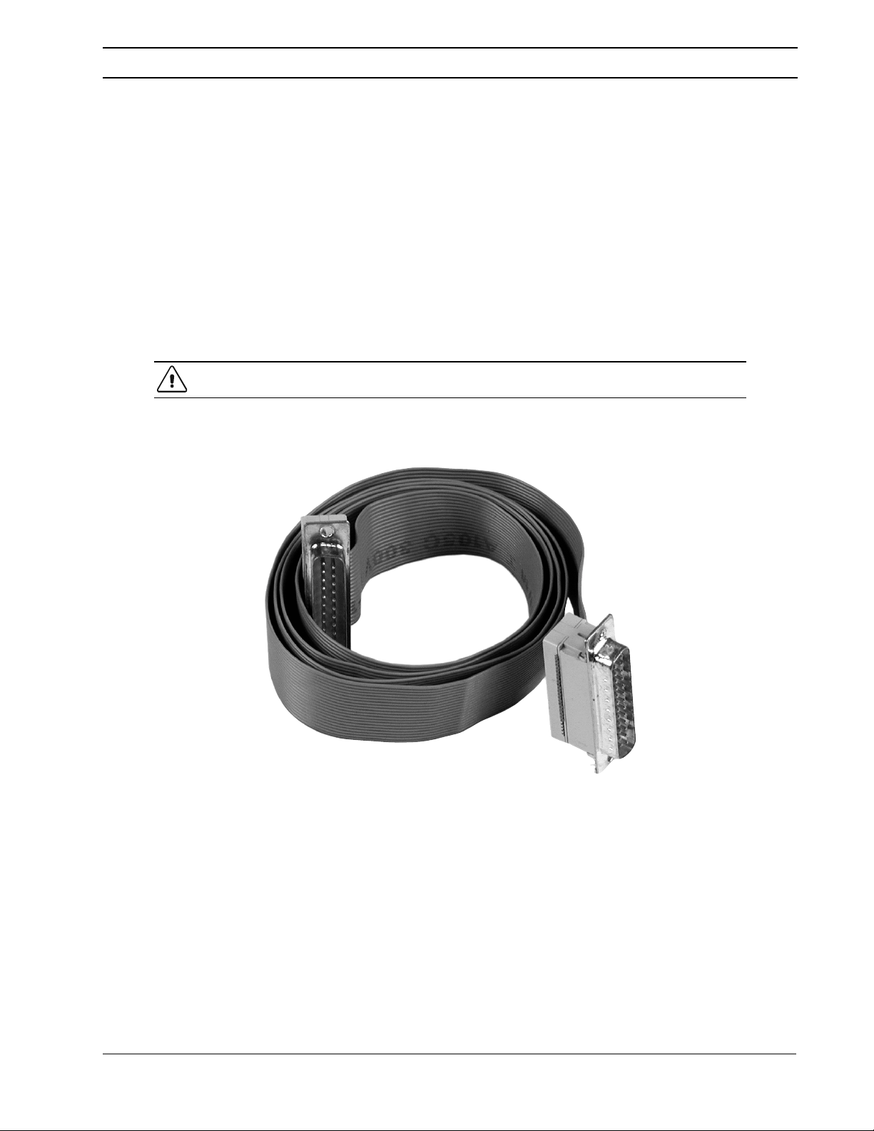
The SWI Stacking Interface Cable kit consists of:
• This Installation Guide
• One 42-inch stacking interface cable, complete with two 25-pin D connectors
CAUTION: Do not use a standard computer cable in place of the SWI stacking interface
cable.
© 2001 Xantrex Technology Inc. All Rights Reserved.
P/N 975-0013-01-01 Rev B 10/01
Figure 1-1
Stacking Interface Cable
1
Page 7

1.0 INTRODUCTION
Notes:
2
© 2001 Xantrex Technology Inc. All Rights Reserved.
P/N 975-0013-01-01 Rev B 10/01
Page 8

2.0 INSTALLATION
Series Stacking
The STACKING port allows two SW or PS Series inverter/chargers to be used in the same system in a “SERIES”
configuration to operate 240 VAC loads. Series stacking can also be used to connect to 240 VAC only power systems
providing both 120 and 240 VAC outputs. A series stacking interface cable (SWI) is required to connect the series
stacking port of the inverters. In this mode, the inverters act independently of each other; however, their output is
phase locked and synchronized 180 degrees out-of-phase. Both units can independently charge the batteries or
provide battery backup power during a utility outage. 230 VAC/50 Hz units can not be stacked.
NOTE: Use tape to label the inverters as INVERTER 1 (L1) and INVERTER 2 (L2), for future
reference.
INVERTER 1 (L1)
NEGATIVE (-) BLACK TERMINAL
NEGATIVE (-) BLACK
INTERCONNECT CABLE
PS STACKING PORT
POSITIVE (+) RED TERMINAL
SWI SERIES STACKING
INTERFACE CABLE
POSITIVE (+) RED
INTERCONNECT CABLE
(not used in installations
with dual disconnects)
PS STACKING PORT
NEGATIVE (-) BLACK TERMINAL
INVERTER 2 (L2)
PS Series DC Interconnect Cables and SWI Series Stacking Cable
© 2001 Xantrex Technology Inc. All Rights Reserved.
P/N 975-0013-01-01 Rev B 10/01
POSITIVE (+) RED TERMINAL
Figure 2-1
7
Page 9

2.0 INSTALLATION
Series Stacking (continued)
TRACE
TRACE
ENGINEERING
ENGINEERING
CONTRAST
ON/OFF
MENU
CONTROL PANEL
SET POINTS
LINE
RESET TO
FACTORY
ITEM
DEFAULTS
MENU
HEADINGS
GEN
MENU
Power Conversion Center
TRACE
ENGINEERING
CONTRAST
TRACE
ENGINEERING
Figure 2-2
SW Series Stacking Interface Cable
ON/OFF
MENU
CONTROL PANEL
SET POINTS
LINE
RESET TO
FACTORYDEFAULTS
ITEM
MENU
HEADINGS
GEN
MENU
Power Conversion Center
8
© 2001 Xantrex Technology Inc. All Rights Reserved.
P/N 975-0013-01-01 Rev B 10/01
Page 10

2.0 INSTALLATION
Series Stacking (continued)
The STACKING port allows two SW or PS Series inverter/chargers to be used in the same system in a “SERIES”
configuration to operate 240 VAC loads. Series stacking can also be used to connect to 240 VAC only power systems
providing both 120 and 240 VAC outputs. A series stacking interface cable (SWI) is required to connect the series
stacking port of the inverters. In this mode the inverters act independently of each other; however their output is
phase locked and synchronized 180 degrees out-of-phase. Both units can independently charge the batteries or
provide battery backup power during a utility outage. 230 VAC/50 Hz units can not be stacked.
NOTE: Use tape to label the inverters as INVERTER 1 (L1) and INVERTER 2 (L2), for future
reference.
Series Stack DC Wiring (one disconnect device)
When stacking two inverters using one DC disconnect device, connect the units and batteries as follows:
• Tie the inverter’s negative terminals together using an appropriate length of cable (sized to fit).
• Connect one of the inverter’s negative terminals to the negative terminal of the battery bank.
• Tie the inverter’s positive terminals together using an appropriate length of cable (sized to fit).
• Connect one of the inverter’s positive terminals to the DC disconnect.
• Connect the DC disconnect to the positive terminal of the battery bank.
• Connect the Series Stacking Cable (SWI) to the STACKING port of both inverters.
• Connect the DC chassis ground lugs of both inverters together using a heavy gauge wire.
• Connect the negative end of the battery bank to a solid earth ground (refer to inverter installation manual).
NOTE: Connect the positive and negative wires to the batteries as show in the illustration
below. This ensures an even charge and discharge through the battery bank.
Inverter 1 (L1)
+
DC
Disconnect
Positive
Tie
Negative
Tie
–
+
–
+
–
+
–
Inverter 2 (L2)
Series Stacking
Cable (SWI)
NOTE: Series Stacking
Cable connects on AC
side for SW inverters
Chassis Ground
–
+
Series Stacking Using One DC Disconnect (Block Diagram)
© 2001 Xantrex Technology Inc. All Rights Reserved.
P/N 975-0013-01-01 Rev B 10/01
–
+
DC Ground
Figure 2-3
9
Page 11

2.0 INSTALLATION
Series Stacking (continued)
Series Stack DC Wiring (two disconnect devices)
When stacking two inverters using two DC disconnect devices, connect the units and batteries as follows (refer
to Figure 2-4):
• Tie the inverter’s negative terminals together using an appropriate length of cable (sized to fit).
• Connect a cable from the L1 inverter’s negative terminal to the negative terminal of the battery bank.
• Connect a cable from the L2 inverter’s negative terminal to the negative terminal of the battery bank.
• Connect a cable from the L1 inverter’s positive terminals to the DC disconnect.
• Connect a short cable from the DC disconnect to the positive terminal of the battery bank.
• Connect a cable from the L2 inverter’s positive terminal to the DC disconnect.
• Connect a short cable from the DC disconnect to the positive terminal of the battery bank.
• Connect the Series Stacking Cable (SWI) to the STACKING port of both inverters.
• Connect the inverter’s DC chassis ground lugs together using a heavy gauge wire.
NOTE: Connect the positive and negative wires to the batteries as show in the illustration
below. This ensures an even charge and discharge through the battery bank.
DC
Disconnect
Inverter 1 (L1)
+
–
Series Stacking
Negative
Tie
DC
Disconnect
Cable (SWI)
NOTE: Series Stacking
Cable connects on AC
side for SW inverters
+
–
–
+
–
+
–
+
Inverter 2 (L2)
–
+
DC Ground
Chassis ground
10
Figure 2-4
Series Stacking Using Two DC Disconnects (Block Diagram)
© 2001 Xantrex Technology Inc. All Rights Reserved.
P/N 975-0013-01-01 Rev B 10/01
Page 12

2.0 INSTALLATION
Series Stacking (continued)
Wiring with a Conduit Box
When wiring a stacked pair of inverters using a conduit box, a longer DC cable must be supplied to connect the
negative terminals of the inverters together. This does not come with the kit and must be obtained separately. The
following illustration shows how the inverters are wired in a conduit box. This wiring arrangement is basically the
same as the previous illustration (Figure 2-Series Stacking (continued)
Battery Connections for Stacked Inverters
When using inverters in a stacked configuration, the same battery bank must be used for both inverters. To
ensure even charging of the batteries, each inverter must be connected to both strings (i.e., positive cable to string
2, and negative cable to string 1 for inverter L1; and positive cable to string 1 and negative cable to string 2 for
inverter L2) as shown in the diagram below. 4).
NOTE: SWCBs (SW Conduit Boxes) or PSCBs (PS Conduit Boxes) may be required to meet
code when stacking inverters.
DC Chassis
Earth Ground
DC
Disconnects
DC Negative
Block
+
+
–
Batteries
–
DC Disconnect Box
–
+
–
+
SWCB (or PSCB)
Conduit Box
+
Inverter 1
(L1)
-
Negative
Tie
+
Inverter 2
(L2)
-
SWCB (or PSCB)
Conduit Box
NOTE: The Series Stacking Cable is
illustrated here to show it connects to
each inverter. Please refer to the
inverter's operator's manual for the
STACKING PORT location.
DC Chassis
Series Stacking
Cable (SWI)
Ground
DC Wiring using a DC Disconnect Box
© 2001 Xantrex Technology Inc. All Rights Reserved.
P/N 975-0013-01-01 Rev B 10/01
Figure 2-5
11
Page 13

2.0 INSTALLATION
CONDUIT FOR
CONDUIT FOR
Series Stacking (continued)
Battery Connections for Stacked Inverters (continued)
When using inverters in a stacked configuration, the same battery bank must be used for both inverters. To
ensure even charging of the batteries, each inverter must be connected to both strings (i.e., positive cable to string
2, and negative cable to string 1 for inverter L1; and positive cable to string 1 and negative cable to string 2 for
inverter L2) as shown in the diagram below.
INVERTER 1
INVERTER 2
– + – +
–
12 Volt
Battery
+
12 Volt
Battery
12 Volt
Battery
12 Volt
Battery
+–
12
Figure 2-6
Example of Battery Connections for Stacked Inverters
© 2001 Xantrex Technology Inc. All Rights Reserved.
P/N 975-0013-01-01 Rev B 10/01
Page 14

2.0 INSTALLATION
Series Stacking (continued)
Series Stacking AC Wiring
Series stacking is used in applications where either 240 volt loads (or a combination of both 240 and
120 volt loads) need to be powered from the inverters. One inverter, connected to the utility’s L1 line,
provides one 120 volt AC output and a second inverter connected to the utility’s L2 line provides the
second 120 volt AC output (180 degrees out-of-phase from the first inverter). The combined out-of-phase
voltages can power 240 volt AC loads as well as 120 volt loads, up to the power rating of the inverters.
Input Wiring (SW Series) (Figure 2-7)
Utility Input
• Connect a wire from the ground bus in the main service panel to the GROUND terminal in the L1
inverter. Connect a second ground wire from the L1 inverter’s AC GROUND terminal to the GROUND
terminal in the L2 inverter.
• Connect a wire from the neutral bus in the main service panel to the NEUTRAL IN terminal in the L1
inverter. Connect a second wire to the NEUTRAL OUT terminal and route this wire to the L2 inverter’s
NEUTRAL IN terminal. Keep this wire as short as possible.
• Connect a wire from the main service panel’s hot L1 line to the
• Connect a wire from the main service panel’s hot L2 line to the
L1L1
L1 inverter’s AC HOT IN 1 terminal.
L1L1
L2L2
L2 inverter’s AC HOT IN 1 terminal.
L2L2
Generator Wiring
• Connect a wire from the generator’s ground terminal to the AC GROUND terminal in the L1 (or L2)
inverter.
• Connect a wire from the generator’s neutral terminal to the NEUTRAL IN 2 terminal in the L1 (or L2
Inverter).
• Connect the generator’s hot wire (120 VAC) to the AC HOT IN 2 terminal in the
L1L1
L1 inverter.
L1L1
If a 120/240 VAC generator is used in the system its hot (L2) output must be connected to the L2
inverter as follows:
• Connect a wire from the generator‘s L2 hot terminal to the AC HOT IN 2 terminal in the
L2L2
L2 inverter.
L2L2
© 2001 Xantrex Technology Inc. All Rights Reserved.
P/N 975-0013-01-01 Rev B 10/01
13
Page 15

2.0 INSTALLATION
Series Stacking (continued)
L1
L2
MAIN SERVICE PANEL
L1
240 VAC
240 VAC
L2
GROUND
NEUTRAL
Main Utility
Breaker
Inverter
Disconnect
Breaker
AC HOT OUT
NEUTRAL
Chassis
AC GROUND
Terminal
SW INVERTER 1
(L1)
NEUTRAL OUT
NEUTRAL IN 2
NEUTRAL IN 1
AC HOT IN 2
AC HOT IN 1
SW INVERTER 2
(L2)
AC HOT OUT
NEUTRAL OUT
NEUTRAL IN 2
NEUTRAL
Chassis
AC GROUND
Terminal
GENERATOR
(OPTIONAL)
To Generator Ground
To Generator Neutral
Generator Hot (to L1 for
120/240 VAC generators)
Generator Hot (to L2 for
120/240 VAC generators)
This line (L2) is for 120/
240 VAC generators only
NEUTRAL IN 1
AC HOT IN 2
AC HOT IN 1
14
Earth Ground
GROUND
Figure 2-7
AC Input Wiring (SW Series Inverter)
© 2001 Xantrex Technology Inc. All Rights Reserved.
P/N 975-0013-01-01 Rev B 10/01
Page 16

2.0 INSTALLATION
Series Stacking (continued)
Input Wiring (PS Series)
Utility Input
• Connect a wire from the ground bus in the service panel to the GROUND terminal in the L1 inverter.
Connect a second ground wire from the inverter’s AC GROUND terminal, to the GROUND terminal in
the L2 inverter.
• Connect a wire from the neutral bus in the main service panel to the NEUTRAL IN terminal in the L1
inverter. Connect a second wire to the NEUTRAL OUT terminal and route this wire to the L2 inverter’s
NEUTRAL IN terminal. Keep this wire as short as possible.
• Connect a wire from the main service panel’s hot L1 line to the L1 inverter’s AC HOT INPUT terminal.
• Connect a wire from the main service panel’s hot L2 line to the L2 inverter’s AC HOT INPUT terminal.
MAIN SERVICE PANEL
L1
L2
NEUTRAL
PS INVERTER 1 (L1) PS INVERTER 2 (L2)
L1
L2
240 VAC
240 VAC
Earth Ground
Main Utility
Breaker
Inverter
Disconnect
Breaker
GROUND
NEUTRAL
GROUND
AC HOT OUTPUT
NEUTRAL OUTPUT
AC CHASSIS
GROUND
LUG
NEUTRAL OUTPUT
NEUTRAL INPUT
AC HOT INPUT
AC HOT OUTPUT
NEUTRAL OUTPUT
AC CHASSIS
GROUND
LUG
NEUTRAL OUTPUT
NEUTRAL INPUT
AC HOT INPUT
© 2001 Xantrex Technology Inc. All Rights Reserved.
P/N 975-0013-01-01 Rev B 10/01
Figure 2-8
AC Input Wiring (PS Series Inverter)
15
Page 17

2.0 INSTALLATION
Series Stacking (continued)
Output Wiring (SW Series)
The output of each inverter provides 120 VAC. The voltage between the HOT outputs from the L1 and L2
inverter is 240 VAC.
• Connect a GROUND wire from the L1 (or L2) inverter’s AC GROUND lug to the sub-panel’s ground bus.
• Connect the NEUTRAL wire from the L1 (or L2) inverter’s NEUTRAL OUT terminal to the neutral bus in the
sub-panel.
• Connect the AC HOT OUTPUT (120 VAC) from the
• Connect the AC HOT OUTPUT (120 VAC) from the
WARNING: ENSURE THE ONLY NEUTRAL/GROUND BOND IS IN THE UTILITY
SERVICE PANEL. REMOVE ANY BONDING FROM THE SUB-PANEL IF IT IS PRESENT.
SW INVERTER 2
AC HOT OUT
NEUTRAL OUT
Chassis
AC GROUND
Terminal
L1
(L2)
NEUTRAL IN 2
AC HOT OUT
Chassis
AC GROUND
Terminal
SW INVERTER 1
(L1)
NEUTRAL OUT
NEUTRAL IN 2
NEUTRAL IN 1
AC HOT IN 1
AC HOT IN 2
NEUTRAL
L1L1
L1 inverter to the L1 terminal in the sub-panel.
L1L1
L2L2
L2 inverter to the L2 terminal in the sub-panel.
L2L2
NEUTRAL IN 1
AC HOT IN 2
AC HOT IN 1
NEUTRAL
L2
L1
L2
NEUTRAL
16
240 VAC
Inverter
240 VAC
Deep Well Pump
240 VAC
Table Saw
Shop Power
120 VAC
Computer
Outlets/Security
120 VAC
Refrigerator
Pellet Stove
Gas Heat Fan
Garage Doors
GROUND
240 VAC
15
15
240 VAC
20
20
120 VAC
15
120 VAC
20
Disconnect
GROUND
Figure 2-9
AC Output Wiring (SW Series Inverters)
SUB-PANEL
© 2001 Xantrex Technology Inc. All Rights Reserved.
P/N 975-0013-01-01 Rev B 10/01
Page 18

2.0 INSTALLATION
Series Stacking (continued)
Output Wiring (PS Series)
The output of each inverter provides 120 VAC. The voltage between the HOT outputs from the L1 and L2
inverter is 240 VAC.
• Connect a GROUND wire from the L1 inverter’s AC GROUND lug to the sub-panel’s ground bus.
• Connect a NEUTRAL wire from the L1 (or L2) inverter’s NEUTRAL OUTPUT to the neutral bus in the subpanel.
• Connect a wire from the HOT (120 VAC) output from the
• Connect a wire from the HOT (120 VAC) output from the
WARNING: ENSURE THE ONLY NEUTRAL/GROUND BOND IS IN THE UTILITY
SERVICE PANEL. REMOVE ANY BONDING FROM THE SUB-PANEL IF IT IS PRESENT.
Chassis
AC GROUND
Terminal
PS INVERTER 1
(L1)
AC HOT OUTPUT
NEUTRAL OUTPUT
NEUTRAL OUTPUT
NEUTRAL INPUT
AC HOT INPUT
PS INVERTER 2
AC HOT OUTPUT
NEUTRAL OUTPUT
Chassis
AC GROUND
Terminal
L1
(L2)
NEUTRAL OUTPUT
NEUTRAL INPUT
L1
L1L1
L1 inverter to the L1 terminal in the sub-panel.
L1L1
L2L2
L2 inverter to the L2 terminal in the sub-panel.
L2L2
AC HOT INPUT
NEUTRAL
L2
L2
NEUTRAL
Deep Well Pump
Table Saw
Shop Power
Computer
Outlets Security
Refrigerator
Pellet Stove
Gas Heat Fan
Garage Doors
AC Output Wiring (PS Series Inverters)
© 2001 Xantrex Technology Inc. All Rights Reserved.
P/N 975-0013-01-01 Rev B 10/01
240 VAC
240 VAC
120 VAC
120 VAC
GROUND
Figure 2-10
240 VAC
15
15
240 VAC
20
20
120 VAC
15
120 VAC
20
240 VAC
Breaker
GROUND
Main
SUB-PANEL
17
Page 19

2.0 INSTALLATION
A
Series Stacking (continued)
Main Service Panel
L1 L2
N
G
Utility L1
N
Stacking
Interface
Cable
Utility L2
N
All connections are made on
the inverter's AC terminal block.
Output L1
Neutral
Neutral
N
G
Output L2
N
G
HOT
N
G
HOT
N
G
The NEUTRAL wires together
at the inverter terminal block.
120 VAC
HOT L1
HOT L2
N
G
120 VAC
240 VAC
Figure 2-11
Series Stacked Inverters AC Wiring
240 VAC Only Source
A 240 VAC source does not allow for the connection of 120 VAC input inverters as no neutral line is supplied
from the utility. In order to use stacked inverters, a neutral line must be added by using a center tapped
autotransformer (such as a T240) on the inverter’s input. This will create the necessary neutral return line for the
inverters, and half the voltage for each inverter to 120 VAC. The output of the inverter supplies both 120 and 240
VAC to the loads. A Trace Series Stacking cable (SWI) and autotransformer (capable of handling the systems power
requirements) are required in this configuration.
Wire the inverters as shown in the diagram below for 240 VAC only sources.
Main Service Panel
240 VAC Only Service
L2
Auto
Transformer
L1
Series
Stacking
Cable
L1
N
N
L2
Utility L1
N
Utility L2
N
ll Connections are
made on the inverter's
AC terminal blocks.
Output L1
Neutral
Output L2
Neutral
HOT
N
G
HOT
N
G
Figure 2-12
Series Stacked Inverters Connected to a 240 VAC Only Source
WARNING: WHEN STACKING INVERTERS, ALWAYS CONNECT THE CHASSIS OF EACH
INVERTER TOGETHER USING THE CHASSIS GROUND LUG; OTHERWISE, A HAZARDOUS VOLTAGE MAY BE PRESENT BETWEEN EACH CHASSIS.
120 VAC
HOT
HOT
N
G
120 VAC
Tie Neutral wires
together at the inverter
terminal block.
L1
L2
240 VAC
18
© 2001 Xantrex Technology Inc. All Rights Reserved.
P/N 975-0013-01-01 Rev B 10/01
Page 20

3.0 OPERATION
Operating Stacked Inverters
Stacked inverters must operate together in order to provide the 120/240 VAC to the loads. The Series Stacking
Interface cable ensures the output from each inverter is 180 degrees out-of-phase for operating 240 VAC loads.
NOTE: Until the units are tested, do no connect loads to the inverters 120 or 240 VAC output.
Start-up and Test
1. Ensure the main service panel’s circuit breakers feeding the inverters are OFF.
2. Switch ON both inverters. The inverter should be providing 120/240 VAC to the sub-panel.
3. Use an AC voltmeter and measure the voltage between the L1 terminal and neutral bus in the sub-panel.
This voltage should be 120 VAC (± 3%).
4. Measure the voltage between the L2 terminal and neutral bus in the sub-panel. This voltage should be 120
VAC (± 3%).
5. Measure the voltage between the L1 and L2 terminals in the sub-panel. This voltage should be 240 VAC (±
3%).
6. Switch ON the main service panel’s circuit breakers feeding the inverters.
7. Verify the inverters are charging the batteries and powering the sub-panel (refer to the operator’s manual).
8. Switch both inverters OFF.
9. Replace all covers and panels on the inverters and sub-panel.
The stacked inverter system is now ready for use.
NOTE: If the inverters are not operating properly, please refer to the operator’s manual for
setup and troubleshooting information.
© 2001 Xantrex Technology Inc. All Rights Reserved.
P/N 975-0013-01-01 Rev B 10/01
19
Page 21

3.0 OPERATION
Settings
When operating PS or SW Series inverters in a series stacked configuration the following settings must be
changed (via an SWRC/SWCA for PS Series inverters) for proper operation.
Automatic and Manual Generator Control
When multiple inverters are used with a generator, the inverter connected to the generator via the Generator
Relay Module (GRM) is designated as the “generator controlling” inverter. The most efficient battery charging is
achieved by setting the charging parameters of each inverter slightly differently (using an SWRC/SWCA for PS
Series inverters).
Bulk and Float Charging
• Set the
BULK VOLTS DC
to the same setting on both inverters.
• Set the
FLOAT VOLTS DC
to the same setting on both inverters.
• Set the Absorption time for a shorter period on the “generator controlling” inverter. When the “generator
controlling” inverter reaches the
FLOAT VOLTS DC
level, it will shut down the generator.
Equalize Charging
• Set both inverters to the same
• Set the
EQUALIZE TIME
• To start an Equalize charge (manually or automatically), set both inverters to
EQUALIZE VOLTS DC
setting.
on the “generator controlling” inverter to a shorter equalize time.
EQ
(accessible by pressing the
green GEN MENU button on the SWRC). This allows both inverters to charge at the equalize voltage.
• During the equalize charge the BULK LED will slowly flash on each inverter, indicating the EQ selection has
been set via the
SET GENERATOR
menu item.
Automatic Equalize Charging
If the inverters are set to automatically charge the batteries via the generator, the equalize process will begin
during the next, automatically started, generator run period. When the equalizing process has completed, the
generator automatically stops and the cursor returns to the
the “generator controlling” inverter. The “non-generator controlling” inverter must be set from EQ to
SET GENERATOR
menu item or the inverter will start another equalize charge the next time the generator is
AUTO
position in the
SET GENERATOR
menu item on
OFF
from the
started.
Manual Equalize Charging
If the batteries were equalized using a manually started generator or from the utility grid, the FLOAT LED
illuminates, indicating the equalization process is complete. Set the cursor to
GENERATOR
menu item when the equalization process is complete.
OFF
on both inverters under the
SET
20
NOTE: If using multiple battery temperature sensors (BTS) ensure they are all connected to
the same location (battery).
© 2001 Xantrex Technology Inc. All Rights Reserved.
P/N 975-0013-01-01 Rev B 10/01
Page 22

tt
t 1 360 435 8826
tt
ff
f 1 360 435 2229
ff
drc@xantrex.com
www.xantrex.com
P/N 975-0013-01-01 Rev B 10/01
 Loading...