

Page 1

Installation Guide
Grid Tie Interface (GTI)
SW Series
SW4024, SW4048, SW5548
Page 2

ii
© 2002 Xantrex Technology Inc.
P/N 975-0041-01-02 Rev A 03/02
About Xantrex
Xantrex Technology Inc., is a world-leading supplier of advanced power
electronics and controls with products from 50 watt mobile units to 1 MW utilityscale systems for wind, solar, batteries, fuel cells, microturbines, and backup power
applications in both grid-connected and stand-alone systems. Xantrex products
include inverters, battery chargers, programmable power supplies, and variable
speed drives that convert, supply, control, clean, and distribute electrical power.
Trademarks
Trace and Xantrex are registered trademarks of Xantrex International.
Notice of Copyright
Grid Tie Interface (GTI) Installation Guide ©March 2002 Xantrex Technology
Inc. All rights reserved.
Disclaimer
While every precaution has been taken to ensure the accuracy of the contents
of this guide, Xantrex International assumes no responsibility for errors or
omissions. Note as well that specifications and product functionality may change
without notice.
Since the use of this manual and the conditions or methods of installation,
operation, use and maintenance of the unit are beyond the control of Xantrex
Technology Inc., the company does not assume responsibility and expressly
disclaims liability for loss, damage, or expense arising out of or any way connected
with such installation, operation, use, or maintenance.
Due to continual improvement through product updates, photographs and/or
illustrations used in this manual may not
exactly
match your unit. Xantrex
Technology Inc., reserves the right to update this product without notice or releasing
an updated manual when
fit, form or function
are not affected.
Date and Revision
March 2002, Revision A
Part Number
975-0041-01-02
Contact Information
Web: www.xantrex.com
Email: dpm@xantrex.com
Phone: 360/435.8826
Fax: 360/435.2229
Page 3
© 2002 Xantrex Technology Inc.
P/N 975-0041-01-02 Rev A 03/02
iii
IMPORTANT SAFETY INSTRUCTIONS
This manual contains important safety instructions that should be followed
during the installation and maintenance of this product.
To reduce the risk of electrical shock, and to ensure the safe installation and
operation of this product, the following safety symbols have been placed
throughout this manual to indicate dangerous conditions and important safety
instructions.
WARNING WARNING
WARNING WARNING
WARNING - A DANGEROUS VOLTAGE OR
CONDITION EXISTS IN THIS AREA. USE EXTREME
CAUTION WHEN PERFORMING THESE TASKS.
AA
AA
A
VERTISSEMENT VERTISSEMENT
VERTISSEMENT VERTISSEMENT
VERTISSEMENT - UNE TENSION OU CONDITION
DANGEREUSE EXISTE DANS CETTE ZONE. FAIRE
PREUVE D’EXTRÊME PRUDENCE LORS DE LA
RÉALISATION DE CES TÂCHES.
CAUTION CAUTION
CAUTION CAUTION
CAUTION - This procedure is critical to the safe
installation or operation of the unit. Follow these
instructions closely.
AA
AA
A
TTENTION TTENTION
TTENTION TTENTION
TTENTION - Cette procédure est essentielle à
l’installation ou l’utilisation de l’unité en toute
sécurité. Suivre ces instructions de près.
NOTE NOTE
NOTE NOTE
NOTE - This statement is important. Follow instructions
closely.
NOTE NOTE
NOTE NOTE
NOTE - Cette déclaration est importante. Suivre les
instructions de près.
• All electrical work must be done in accordance with local, national, and/or
international electrical codes.
• Before installing or using this device, read all instructions and cautionary
markings located in the manual, and on the inverter, the batteries, and the PV
array.
• Do not expose this unit to rain, snow, or liquids of any type. This product is
designed only for indoor mounting.
• To reduce the chance of short-circuits use instulated tools when installing or
working with the inverter, the batteries, or the PV array.
• Remove all jewelry while installing this system. This will greatly reduce the
chance of accidental exposure to live circuits.
Page 4

iv
© 2002 Xantrex Technology Inc.
P/N 975-0041-01-02 Rev A 03/02
SAVE THESE INSTRUCTIONS
• The unit contains more than one live circuit (inverter and utility grid). Power
may be present at more than one source.
• This product contains no user-serviceable parts. Do not attempt to repair this
unit.
• To reduce risk of electric shock, disconnect all wiring before attempting any
maintenance or cleaning.
• Do not mount this device in unventilated enclosures.
• To reduce risk of electric shock, disconnect all wiring before attempting any
maintenance or cleaning.
• Additional AC disconnects may be required as part of the system installation.
Consult local and national electrical code requirements.
• This unit is designed to be horizontally wall mounted.
• The AC input and output neutral conductors are not connected (bonded) to
the chassis.
• The AC input and output HOT conductor are not isolated from each other.
• The chassis housing of the GTI must be connected to a permanent grounding
system as required by the National Electric Code, ANSI/NFPA 70-1996. This is
the responsibility of the system installer. A grounding terminal lug is provided
for connection of an equipment grounding conductor.
• CSA certified for sale in the U.S. under Photovoltaic Power Systems (UL1741).
IMPORTANT SAFETY INSTRUCTIONS (Continued)
Page 5

© 2002 Xantrex Technology Inc.
P/N 975-0041-01-02 Rev A 03/02
v
CC
CC
C
ontentsontents
ontentsontents
ontents
IMPORTANT SAFETY INSTRUCTIONS ............................................................. iii
1.0 INTRODUCTION1.0 INTRODUCTION
1.0 INTRODUCTION1.0 INTRODUCTION
1.0 INTRODUCTION
............................................................................................................................
............................................................................................................................
..............................................................
11
11
1
Introduction .......................................................................................................... 1
Standard Features .................................................................................................4
Utility Interactive Mode ....................................................................................4
Bypass Mode .................................................................................................... 4
2.0 INST2.0 INST
2.0 INST2.0 INST
2.0 INST
ALLAALLA
ALLAALLA
ALLA
TIONTION
TIONTION
TION
..................................................................................................................................
..................................................................................................................................
.................................................................
55
55
5
Pre-Installation ......................................................................................................5
Required Tools and Materials .......................................................................... 5
Removing the Top Cover .................................................................................. 5
Mounting ...............................................................................................................6
Procedure ..........................................................................................................6
Wiring .................................................................................................................... 8
AC Wiring for Single-Inverter Installations ......................................................8
Ground Wiring ........................................................................................... 10
Utility Grid AC Wiring to the GTI .............................................................. 12
Inverter AC Input Wiring to the GTI ..........................................................14
Inverter AC Output Wiring to the GTI .......................................................16
GTI Wiring to the Sub-Panel ......................................................................18
Communications Cable ............................................................................. 20
AC Wiring for Dual-Inverter Installations ...................................................... 22
Ground Wiring ........................................................................................... 24
Utility Grid AC Wiring to Dual GTIs ..........................................................26
Inverter AC Input and Output Wiring to the GTIs ...................................28
GTI Wiring to the Sub-Panel ......................................................................30
Connecting the Communications Cables for Dual Inverter Installations 30
AC Rewiring for Dual-Inverter Power Panel Installations ............................. 32
AC Rewiring for Power Module Installations ................................................ 34
AC Rewiring for Power Module Installations (continued) ............................36
Wiring Check ....................................................................................................... 37
Operating Stacked Inverters ...............................................................................37
Start-up and Test .................................................................................................37
3.0 TROUBLESHOOTING3.0 TROUBLESHOOTING
3.0 TROUBLESHOOTING3.0 TROUBLESHOOTING
3.0 TROUBLESHOOTING
..........................................................................................................
..........................................................................................................
.....................................................
3939
3939
39
APPENDIX A – SPECIFICAAPPENDIX A – SPECIFICA
APPENDIX A – SPECIFICAAPPENDIX A – SPECIFICA
APPENDIX A – SPECIFICA
TIONSTIONS
TIONSTIONS
TIONS
..................................................................................
..................................................................................
.........................................
A-1A-1
A-1A-1
A-1
Electrical Specifications1 .................................................................................. A-1
Mechanical Specifications ................................................................................ A-1
APPENDIX B – PRODUCT AND SYSTEM INFORMAAPPENDIX B – PRODUCT AND SYSTEM INFORMA
APPENDIX B – PRODUCT AND SYSTEM INFORMAAPPENDIX B – PRODUCT AND SYSTEM INFORMA
APPENDIX B – PRODUCT AND SYSTEM INFORMA
TIONTION
TIONTION
TION
........
........
....
B-1B-1
B-1B-1
B-1
Warranty ............................................................................................................ B-1
Return Material Authorization Policy ............................................................... B-2
Return Material Procedure ........................................................................... B-2
Service Information .......................................................................................... B-3
Page 6

vi
© 2002 Xantrex Technology Inc.
P/N 975-0041-01-02 Rev A 03/02
List of FiguresList of Figures
List of FiguresList of Figures
List of Figures
Figure 1-1 Grid Tie Interface Flow Diangram .......................................................... 2
Figure 1-2 Grid Tie Interface Flow Diagram
with External Manual Bypass Switch ................................................. 3
Figure 1-3 Grid Tie Interface Unit .............................................................................4
Figure 2-1 Removing the Top Cover ......................................................................... 5
Figure 2-2 Mounting Holes ...................................................................................... 6
Figure 2-3 Dimensional Drawing (Not to scale) ..................................................... 7
Figure 2-4 GTI Circuit Board Enlargement ...............................................................8
Figure 2-5 AC Input and Output Wiring for Single-Inverter Installations .............. 9
Figure 2-5a Ground Wiring for a Single-Inverter Installations ................................ 11
Figure 2-5b Utility Grid AC Wiring to the GTI ..........................................................13
Figure 2-5c Inverter AC Input Wiring to the GTI ..................................................... 15
Figure 2-5d Inverter AC Output Wiring to the GTI .................................................. 17
Figure 2-5e GTI Wiring to the Sub-Panel ................................................................. 19
Figure 2-6 GTI Communications Cable Location .................................................. 20
Figure 2-7 Connecting the Communications Cable to the Circuit Board ............. 21
Figure 2-8 Wiring Diagram for Dual-Inverter Installations ................................... 23
Figure 2-8a Ground Wiring for Dual-Inverter Installations ..................................... 25
Figure 2-8b Utility Grid AC Wiring to Dual GTIs ..................................................... 27
Figure 2-8c Inverter AC Input and Output Wiring to Dual GTIs ............................ 29
Figure 2-8d GTI Wiring to the Sub-Panel ................................................................. 31
Figure 2-9 Re-wiring Power Panel Installations to include dual GTIs ................... 33
Figure 2-10 Original Power Module Wiring ............................................................. 35
Figure 2-10a Power Module Rewiring for dual GTI Installations ..............................36
Page 7

© 2002 Xantrex Technology Inc.
P/N 975-0041-01-02 Rev A 03/02
1
1.0 INTRODUCTION
INTRODUCTION
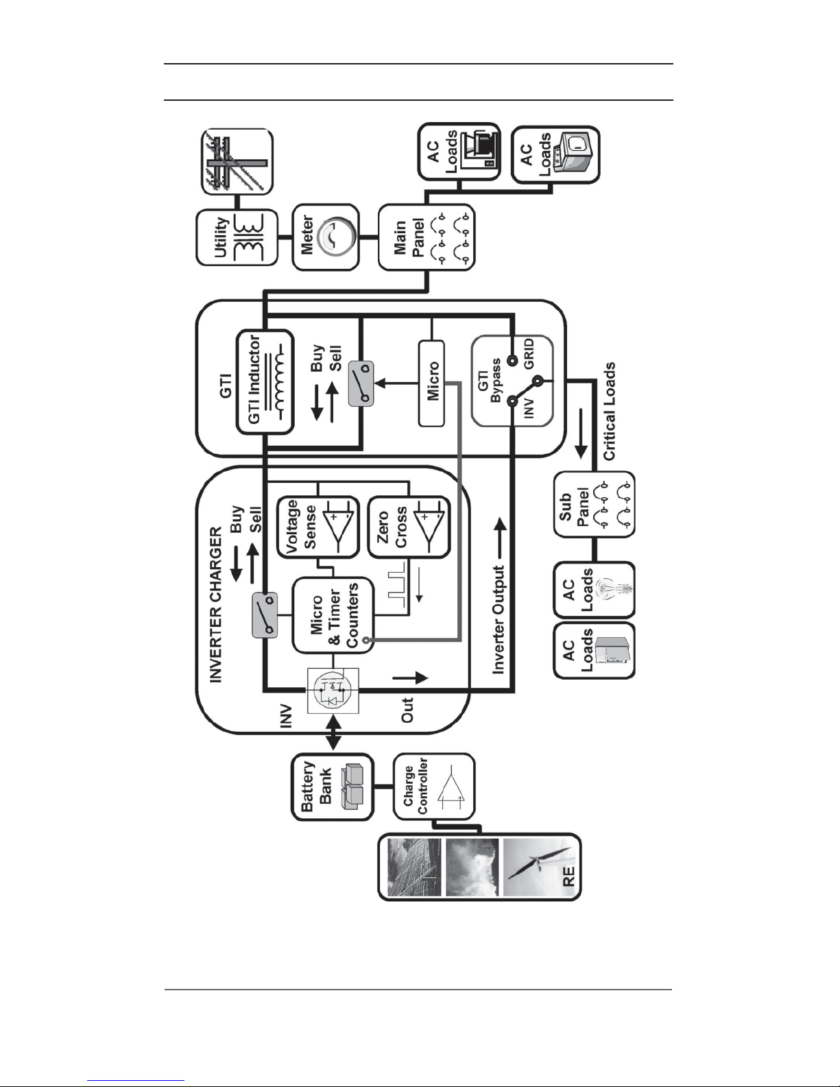
The Grid Tie Interface (GTI) is an integrated assembly used with the Trace™
SW Series II inverter/charger with Revision 4.2 (or higher) software. This new device
provides active anti-islanding protection and reduces current Total Harmonic
Distortion (THD) as required in UL-1741-2000.
The Grid Tie Interface is an accessory, which is connected between the grid, the
AC loads, and the SW Series II inverter to optimize the “SELL” feature. While there
is a small inductor in the GTI, this device is not a “filter”; rather it contains an
additional control microprocessor, which connects to the SW Series II with a
communications cable.
When the GTI is connected and the Inverter “SELL” mode is selected, the
microprocessor of the GTI takes control of the SW Series II and operates the inverter
“SELL” feature. The GTI affords a dedicated microprocessor and new, sophisticated
control algorithms that are able to optimize the sell function.
The SW Series II with the GTI meets all power quality requirements of UL1741,
including harmonic distortion, power factor, and anti-islanding requirements. In
addition, it has increased the SW Series II’s efficiency in SELL mode to within 1% of
the impressive off-grid efficiency of the SW.
The GTI also contains an automatic transfer/shorting relay, which the SW
Series II uses to disconnect the GTI from the circuit when it is not needed, for
example when the SW Series II is charging batteries from the grid. This is also used
to disconnect the GTI so that it does
NOTNOT
NOTNOT
NOT
represent a phantom load or parasitic
loss to the system.
All new SW Series II units (manufactured since December of 2001) are
equipped to allow the GTI to be installed in the field. The SW Series II inverter is
Certified to UL1741 for off grid and backup power applications. The SW can be
connected to the grid as a battery charger; however, it is
NOTNOT
NOTNOT
NOT
approved to use the
SELL feature (net meter) without the GTI accessory. The GTI carries all necessary
approvals and markings to allow a safety inspector to approve the installation for net
metering.
Page 8
1.0 INTRODUCTION
2
© 2002 Xantrex Technology Inc.
P/N 975-0041-01-02 Rev A 03/02
Figure 1-1
Grid Tie Interface Flow Diagram
Page 9
1.0 INTRODUCTION
© 2002 Xantrex Technology Inc.
P/N 975-0041-01-02 Rev A 03/02
3
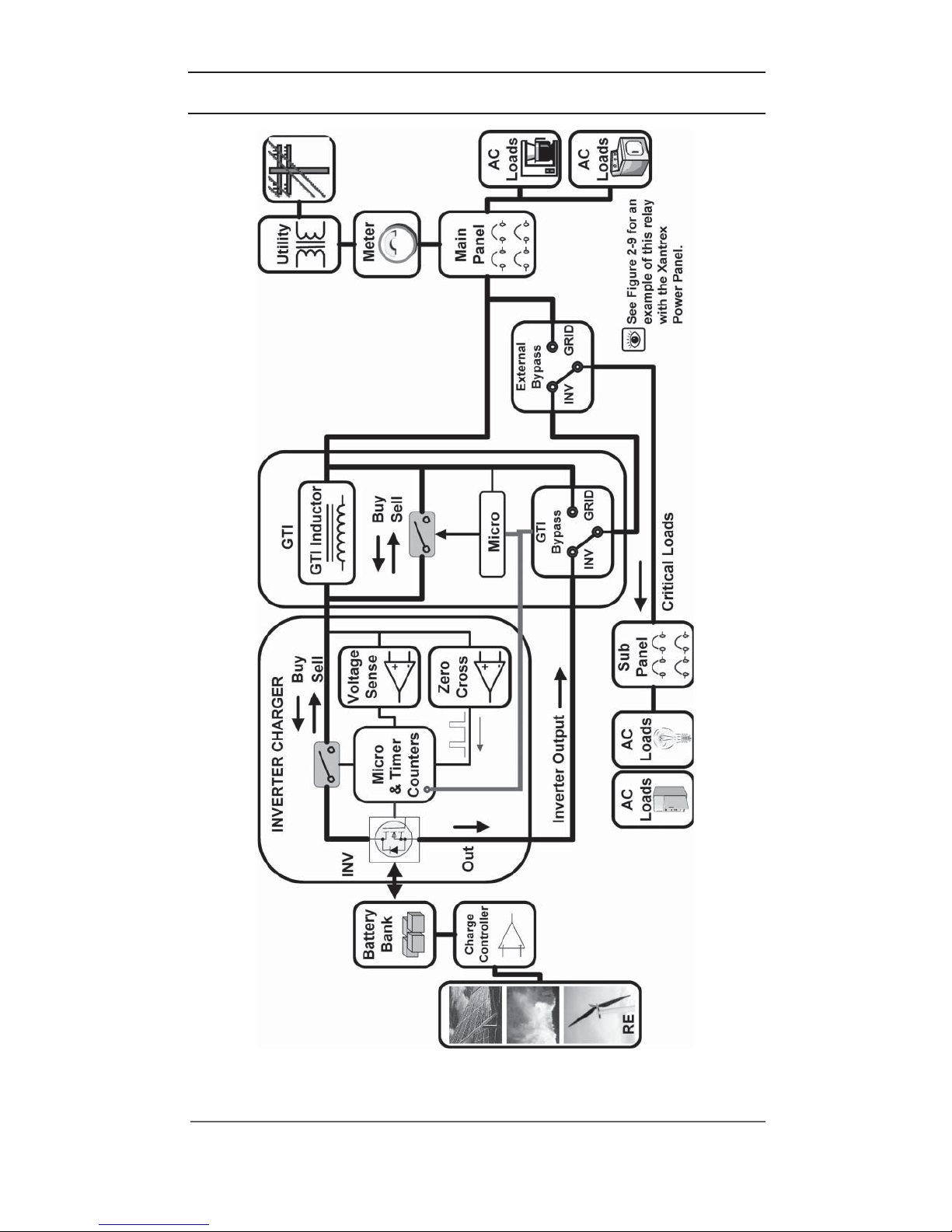
Figure 1-2
Grid Tie Interface Flow Diagram with External Manual Bypass Switch
Page 10

1.0 INTRODUCTION
4
© 2002 Xantrex Technology Inc.
P/N 975-0041-01-02 Rev A 03/02
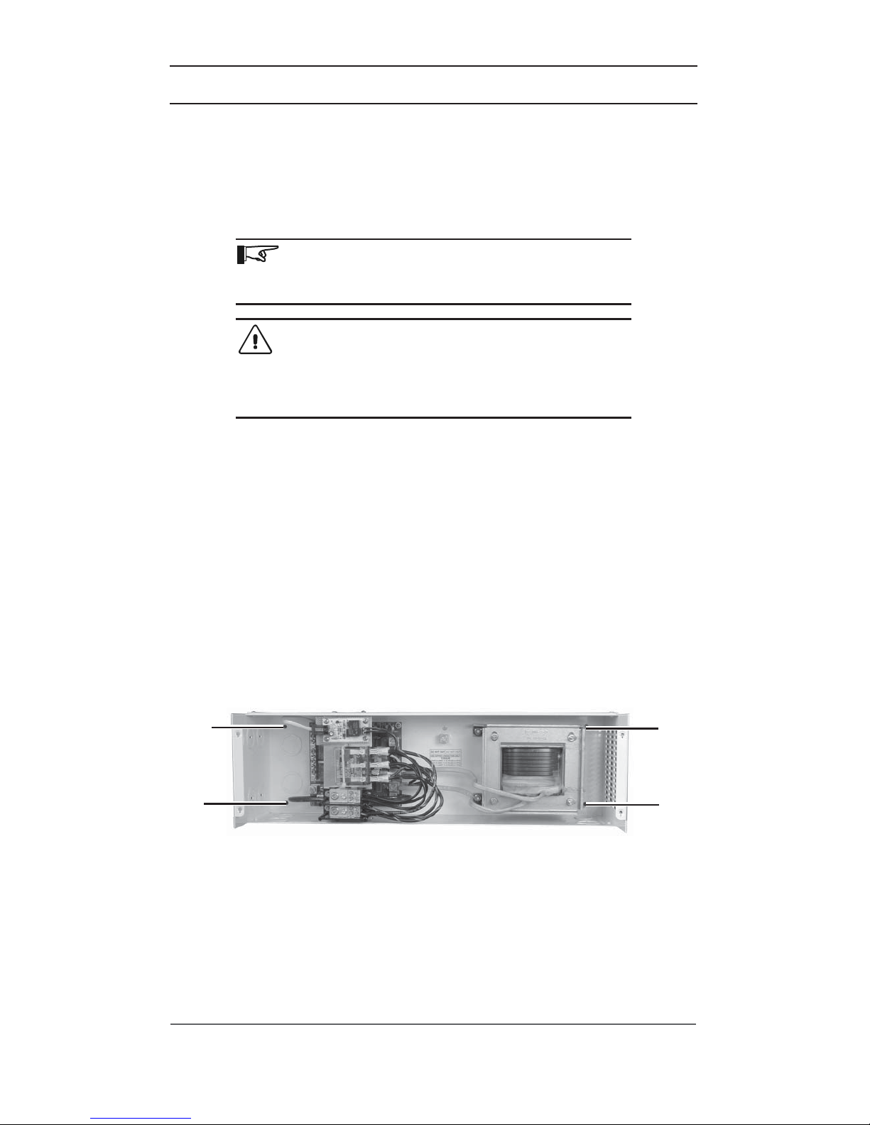
STANDARD FEATURES
The Grid Tie Interface (GTI) is an external unit that is required for use with the
Xantrex SW Series Inverters, models SW4024, SW4048, and SW5548 with Rev. 4.2
firmware or higher, being used in Utility Interactive “Sell” mode. This device ensures
compliance with regulatory standards for utility interface applications.
The GTI utilizes a highly-efficient inductor constructed of high temperature
materials and M-6 grade steel laminations, meeting UL Class-H standards.
The unit is housed in a powder-coated, steel enclosure, suitable for indoor
installations and contains dual knockouts for ¾" - 1" and ½" - ¾" conduit
connections. The unit includes a control board with one 10-pin, polarized, connector
that connects to the SW inverter.
The GTI has two functions: 1) Utility Interactive Mode, and 2) Bypass Mode.
Utility Interactive Mode
Utility Interactive Mode is only engaged when the SW inverter begins selling
power in the “Sell” mode. When in this mode, the GTI engages an inductor
through an internal relay that filters out current harmonics and ensures that the
power transferred to the grid has Total Harmonic Distortion (THD) levels that are
within acceptable ranges and ensures the power factor is high. The GTI also
provides anti-islanding protection in the event of a utility grid failure.
Bypass Mode
The GTI includes a bypass relay that is controlled by the current direction and
levels in the GTI and allows the critical loads to be connected to the grid or to the
output of the SW inverter. When a low level “sell” current begins, the GTI will
engage the bypass relay to allow the loads to be connected to the grid. In this
operation (grid-connected), the inverter’s AC1 relay and the bypass relay work
together to ensure fast transfer of the critical loads in a backup situation.
The critical loads are effectively connected directly to the grid – through the GTI
– rather than passing through the inverter, resulting in the “LOAD AMPS AC” menu
item displayed on the SW inverter to read zero. This zero reading will continue until
the inverter batteries require a “buy” current of 10-15 amps AC or if a loss of grid
power is detected. If either one of these conditions is detected, the bypass relay will
engage to allow the critical loads to be directly powered by the inverter (inverterconnected). The inverter will continue to power the critical loads until another “sell”
current begins, which again switches to the grid-connected operation.
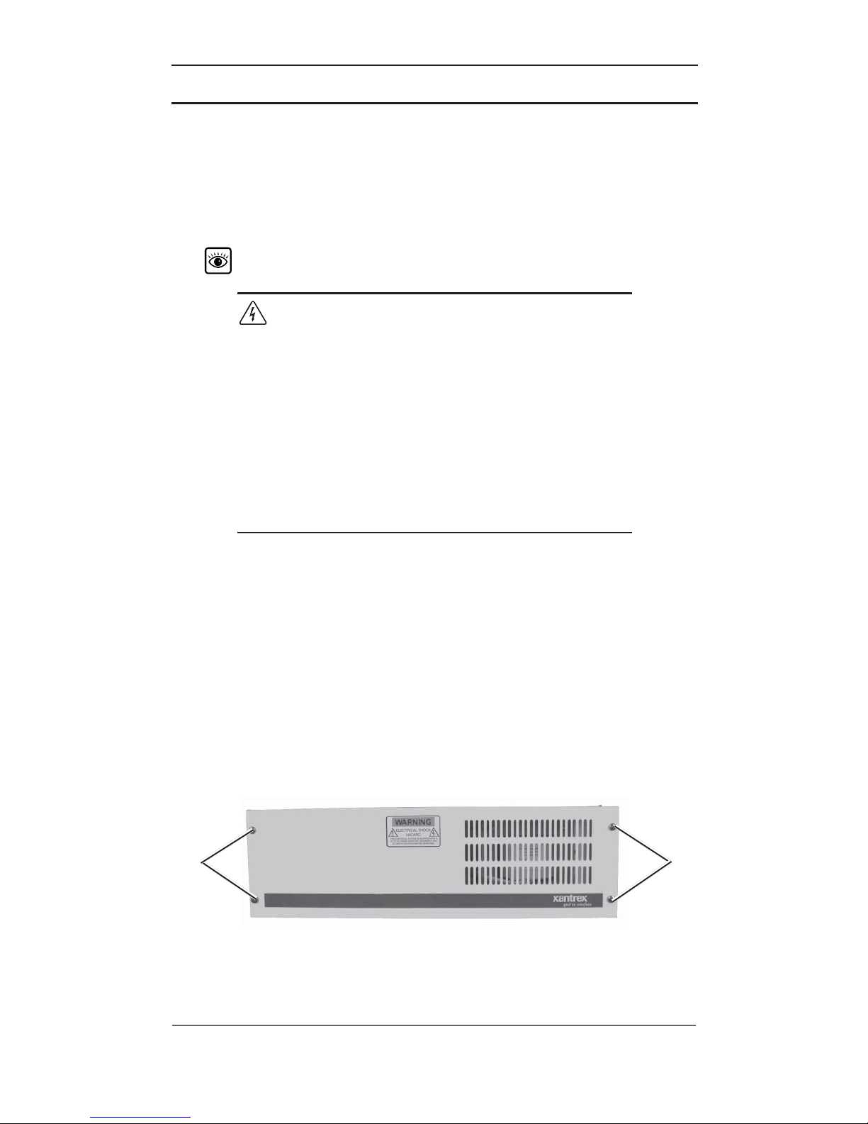
Figure 1-3
Grid Tie Interface Unit
Page 11
© 2002 Xantrex Technology Inc.
P/N 975-0041-01-02 Rev A 03/02
5
2.0 INSTALLATION
PRE-INSTALLATION
The GTI is only designed to work with the SW4024, SW4048 and SW5548
models that have revision 4.2 (or higher) software. Prior to installing the GTI,
ensure that you have the appropriate model, the proper level of software and the
inverter has the communication cable located within.
See Figure 2-6 for the location of this cable.
WARNING: THE CRITICAL LOADS ARE NOW
POWERED THROUGH THE GTI; THESE LOADS
WILL NOT BE POWERED IF THE SW INVERTER OR
THE GTI ARE OFF OR DISCONNECTED. IT IS
RECOMMENDED THAT AN EXTERNAL BYPASS
SWITCH/BREAKER BE INSTALLED BETWEEN THE
GRID AND THE CRITICAL LOAD-PANEL. THIS
SWITCH, WHEN ENGAGED, WILL ALLOW THE
GRID TO DIRECTLY POWER THE LOADS WHILE
THE GTI OR SW INVERTER IS OFF OR
DISCONNECTED. SEE FIGURE 2-9 FOR AN
EXAMPLE OF THIS RELAY IN A XANTREX POWER
PANEL.
Required Tools and Materials
• Wire strippers
• Phillips screw driver
• Slotted screw driver
• Torque wrench
• 3/16" Hex-Head wrench
• #6 AWG Wire
Removing the Top Cover
1. Remove the four Phillips screws and starwashers and set aside. Be sure to
put these screws and washers somewhere where they can’t get lost.
Figure 2-1
Removing the Top Cover
Remove
these
phillips
screws to
remove
top cover
Remove
these
phillips
screws to
remove
top cover
Page 12
2.0 INSTALLATION
6
© 2002 Xantrex Technology Inc.
P/N 975-0041-01-02 Rev A 03/02
Figure 2-2
Mounting Holes
Mounting
Hole
Mounting
Hole
Mounting
Hole
Mounting
Hole
MOUNTING
Place the GTI in a convenient location, close to the inverter. The GTI must
be mounted horizontally on a flat surface (such as a wall) in a clean, dry
environment. Do not mount the GTI where it will be exposed to the weather or in
a damp location.
NOTE: The GTI weighs approximately 25 pounds. Use
appropriate wall anchors or backing material (plywood,
2 x 4’s, etc.) that will support its weight.
CAUTION: Do not mount vertically as water may
enter the enclosure and damage the internal
circuitry. Damage caused by mounting the unit
vertically is NOT covered under the limited
warranty.
Procedure
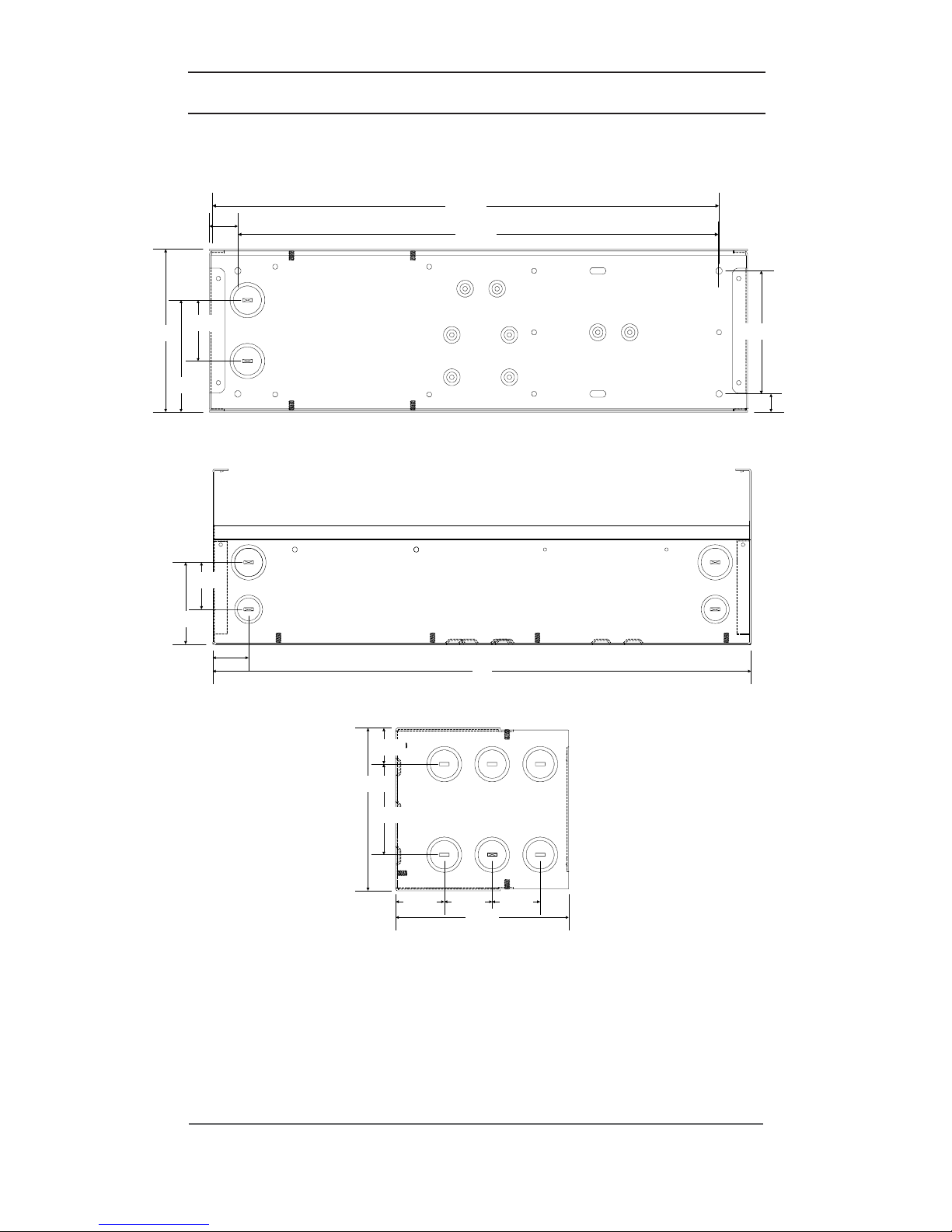
1. Use a level and mark the location for mounting the unit on the wall.
2. Measure out the four mounting screw holes according to Figure 2-3.
3. Use a #10 x 3/8 (or 1/2) inch long screw and washer (and appropriate
anchors if necessary) and mount the GTI securely to the wall or backing
material (plywood, 2 x 4’s, etc.).
4. Remove the appropriate knockouts for the conduit. Install the conduit
between the GTI and the inverter. Use separate conduit for the AC wiring
and the communications cable.
Page 13
2.0 INSTALLATION
© 2002 Xantrex Technology Inc.
P/N 975-0041-01-02 Rev A 03/02
7
Figure 2-3
Dimensional Drawing (Not to scale)
Front Internal view of unit
Side of unit
Ends of unit (both ends)
2 3/8"
4 3/8"
1 1/8"
19 7/8"
4 3/4"
3/4"
6 1/8"
1 3/4"
3 1/8"
1 3/8"
21"
1 7/8" 1 7/8" 1 7/8"
3 1/5"
1 3/8"
6 1/4"
6 3/4"
18 3/4"
Page 14
2.0 INSTALLATION
8
© 2002 Xantrex Technology Inc.
P/N 975-0041-01-02 Rev A 03/02
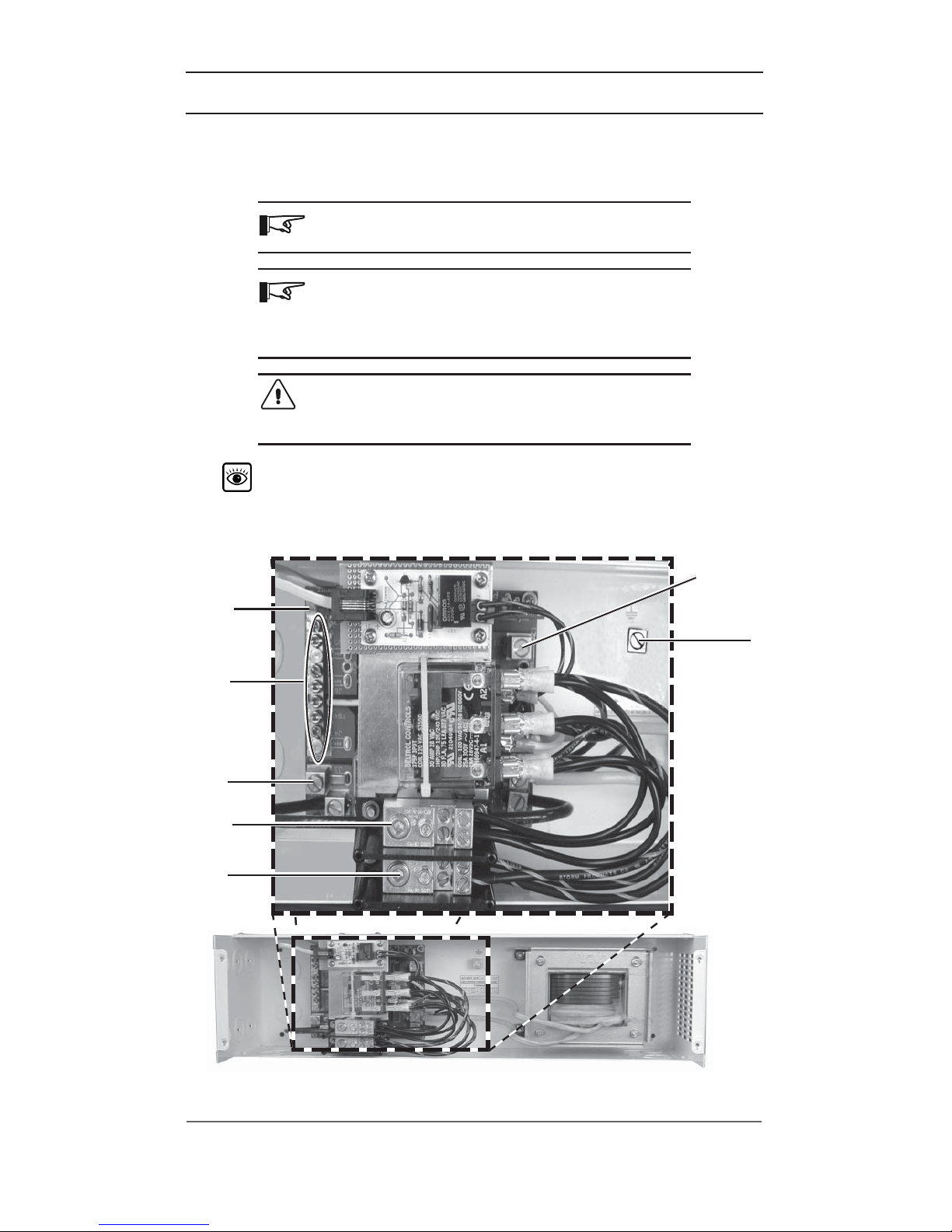
Figure 2-4
GTI Circuit Board Enlargement
WIRING
AC Wiring for Single-Inverter Installations
NOTE: All wiring should be performed by a qualified
person or a licensed electrician.
NOTE: Ensure that wire size and conduit sizes are
appropriate for this installation. AC wiring should be
routed in separate conduits from the communications
cable.
CAUTION: AC pass-through ability through the GTI
is 60 amps. It is recommended to use minimum
#6 AWG (THHN) wiring.
See Figure 2-7 for an enlargement of this circuit board showing the
location of the communications cable port.
NEUTRAL
Bar
AC IN
from the
inverter output
AC OUT
to the
subpanel
AC OUT
to the
inverter’s
AC HOT IN1
Communications
Cable Port
(behind this cable)
AC IN
from the grid
GROUND
LUG
Page 15
2.0 INSTALLATION
© 2002 Xantrex Technology Inc.
P/N 975-0041-01-02 Rev A 03/02
9
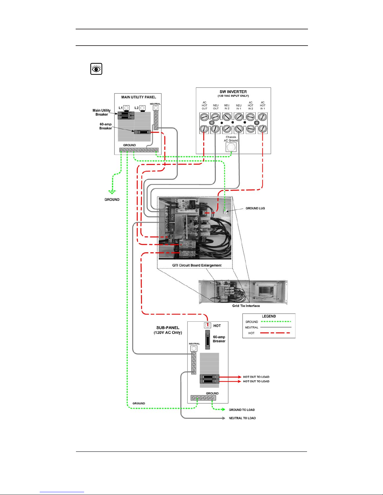
Figure 2-5
AC Input and Output Wiring for Single-Inverter Installations
AC Wiring for Single-Inverter Installations (continued)
See pages 10 through 21 for detailed instructions for AC Input and AC
output wiring for single-inverter/GTI installations.
Page 16

2.0 INSTALLATION
10
© 2002 Xantrex Technology Inc.
P/N 975-0041-01-02 Rev A 03/02
Wiring (continued)
AC Wiring for Single-Inverter Installations (continued)
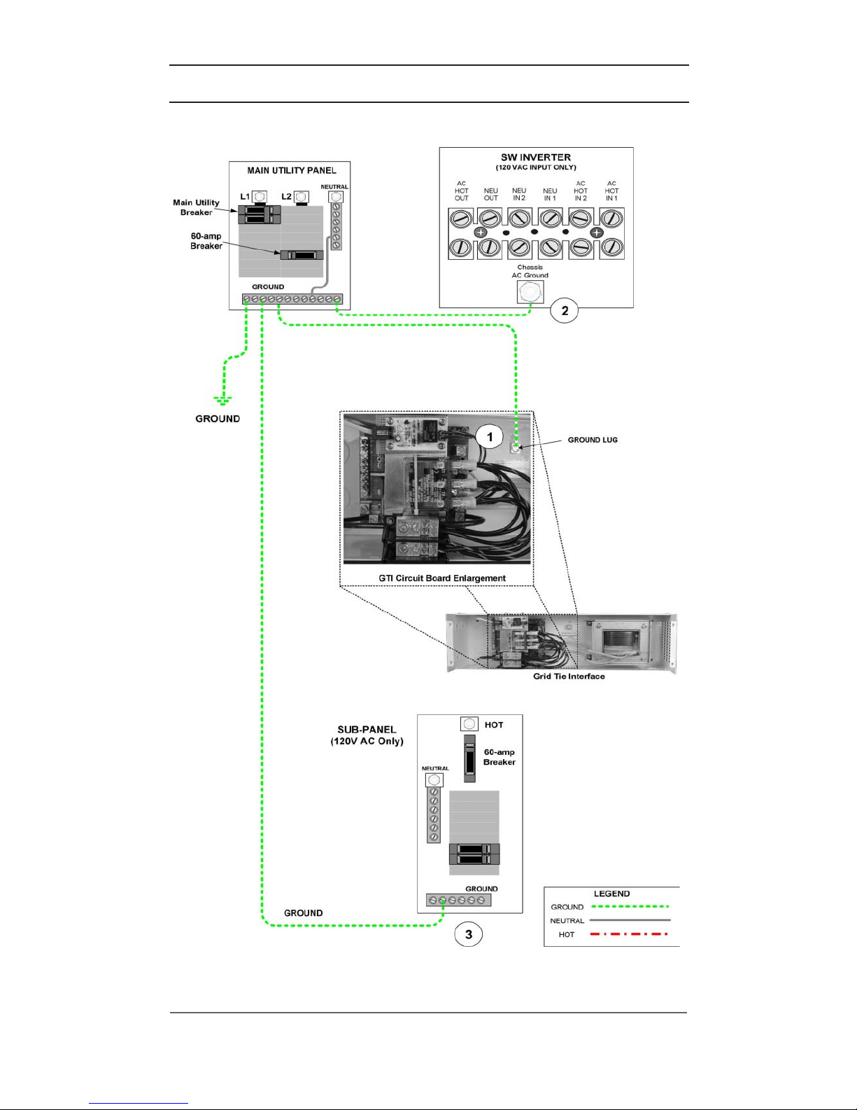
Ground Wiring
Note: Ground wiring must be established at each unit.
Ground wiring can also be accomplished in a variety of
ways. The following instructions describe only one
method. Please consult your local electrician for specific
wiring details pertaining to your installation.
1. Connect a wire from the ground bus in the main service panel to the
ground lug in the GTI.
2. Connect a wire from the ground bus in the main service panel to the
ground terminal in the inverter.
3. Connect a wire from the ground bus in the main service panel to the
ground terminal in the sub-panel.
See Figure 2-5a for an illustration of ground wiring for a single-inverter
installation with the GTI.
Page 17
2.0 INSTALLATION
© 2002 Xantrex Technology Inc.
P/N 975-0041-01-02 Rev A 03/02
11
Figure 2-5a
Ground Wiring for a Single-Inverter Installations
AC Wiring for Single-Inverter Installations (continued)
Page 18

2.0 INSTALLATION
12
© 2002 Xantrex Technology Inc.
P/N 975-0041-01-02 Rev A 03/02
Wiring (continued)
AC Wiring for Single-Inverter Installations (continued)
Utility Grid AC Wiring to the GTI
WARNING: DISCONNECT THE BATTERIES FROM
THE INVERTER IF THEY ARE ALREADY CONNECTED.
1. Ensure the breaker that feeds the GTI is OFF (i.e., no power out). Feed the
HOT and NEUTRAL input wires from the GTI to the main utility panel.
Leave a sufficient amount of extra wire at each end.
2. Confirm a GROUND (green) wire exists from the main utility panel to the
GTI’s AC GROUND lug.
3. Connect the NEUTRAL (white) wire from the main utility panel to the GTI’s
NEUTRAL bar.
4. Connect the HOT (BLACK) wire from a single-pole breaker (60 amps) in
the main utility panel to the GTI’s AC1 HOT IN terminal.
5. Torque all connections to 10 to 15 inch-pounds.
See Figure 2-5b for an illustration of Utility Grid AC Wiring to the GTI.
Page 19

2.0 INSTALLATION
© 2002 Xantrex Technology Inc.
P/N 975-0041-01-02 Rev A 03/02
13
Figure 2-5b
Utility Grid AC Wiring to the GTI
AC Wiring for Single-Inverter Installations (continued)
Page 20

2.0 INSTALLATION
14
© 2002 Xantrex Technology Inc.
P/N 975-0041-01-02 Rev A 03/02
Inverter AC Input Wiring to the GTI
1. Feed the HOT and NEUTRAL input wires from the inverter to the GTI.
Leave three to six inches of extra wire at each end.
2. Connect the NEUTRAL (white) wire from the GTI’s NEU OUT terminal to
the inverter’s NEUTRAL IN 1 terminal.
3. Connect the AC1 HOT OUT (BLACK) wire from the GTI to the inverter’s
AC1 HOT IN terminal.
4. Torque all connections to 10 to 15 inch-pounds.
See Figure 2-5c for an illustration of the inverter AC input wiring to the
GTI.
Wiring (continued)
AC Wiring for Single-Inverter Installations (continued)
Page 21

2.0 INSTALLATION
© 2002 Xantrex Technology Inc.
P/N 975-0041-01-02 Rev A 03/02
15
AC Wiring for Single-Inverter Installations (continued)
Figure 2-5c
Inverter AC Input Wiring to the GTI
Page 22

2.0 INSTALLATION
16
© 2002 Xantrex Technology Inc.
P/N 975-0041-01-02 Rev A 03/02
Inverter AC Output Wiring to the GTI
WARNING: ENSURE THE SUB-PANEL DOES NOT
HAVE A NEUTRAL-TO-GROUND BOND. IF IT
DOES, REMOVE IT. ALL AC NEUTRAL-GROUND
BONDING IS DONE AT THE MAIN UTILITY PANEL.
1. Connect a NEUTRAL (white) wire to the inverters’s NEUTRAL OUT
terminal.
2. Connect the other end of this same NEUTRAL wire to the NEUTRAL bar in
the GTI.
3. Connect a HOT (Black) wire to the inverter’s terminal labeled AC HOT
OUTPUT.
4. Connect the other end of the HOT (black) wire from the inverer’s AC HOT
OUT terminal to the GTI’s HOT IN terminal.
5. Torque all connections to 10 to 15 inch-pounds.
See Figure 2-5d for an illustration of the inverter AC output wiring to
the GTI.
Wiring (continued)
AC Wiring for Single-Inverter Installations (continued)
Page 23

2.0 INSTALLATION
© 2002 Xantrex Technology Inc.
P/N 975-0041-01-02 Rev A 03/02
17
Figure 2-5d
Inverter AC Output Wiring to the GTI
AC Wiring for Single-Inverter Installations (continued)
Page 24

2.0 INSTALLATION
18
© 2002 Xantrex Technology Inc.
P/N 975-0041-01-02 Rev A 03/02
Wiring (continued)
AC Wiring for Single-Inverter Installations (continued)
GTI Wiring to the Sub-Panel
WARNING: ENSURE THE SUB-PANEL DOES NOT
HAVE A NEUTRAL-TO-GROUND BOND. IF IT
DOES, REMOVE IT. ALL AC NEUTRAL-GROUND
BONDING IS DONE AT THE MAIN UTILITY PANEL.
1. Connect a NEUTRAL (white) wire to the GTI’s NEUTRAL bar.
2. Connect the other end of this NEUTRAL wire to the NEUTRAL bar in the
sub-panel.
3. Connect the HOT (black) wire to the GTI’s AC HOT OUT terminal.
4. Connect the other end of this HOT (black) wire to the sub-panels HOT IN
terminal.
5. Torque all the inverter’s connections to 10 to 15 inch-pounds.
NOTE: Consult the sub-panel manufacturer’s
specifications for wire torques on the sub-panel
connections. Use those torque requirements if different.
Page 25

2.0 INSTALLATION
© 2002 Xantrex Technology Inc.
P/N 975-0041-01-02 Rev A 03/02
19
AC Wiring for Single-Inverter Installations (continued)
Figure 2-5e
GTI Wiring to the Sub-Panel
Page 26

2.0 INSTALLATION
20
© 2002 Xantrex Technology Inc.
P/N 975-0041-01-02 Rev A 03/02
Wiring (continued)
Communications Cable
Figure 2-6
GTI Communications Cable Location
1. Remove the access panel on the bottom of the inverter.
2. Clip the cable binding and gently remove the loose end of the
communications cable from inside of the inverter. It will be located directly
behind the AC Terminal Block. This cable extends approximately 2.5 feet
out of the inverter.
3. Connect the loose end of the communications cable to the communications
cable port on the GTI circuit board.
See Figure 2-7 for the location of the communications port inside the
GTI.
Communications
Cable
Remove this
screw to remove
the access panel.
Remove this screw
to remove the
access panel.
Cable binding
Page 27

2.0 INSTALLATION
© 2002 Xantrex Technology Inc.
P/N 975-0041-01-02 Rev A 03/02
21
Wiring (continued)
Communications Cable (continued)
Figure 2-7
Connecting the Communications Cable to the Circuit Board
NOTE: An additional 8-foot 10-conductor extension cable
is available at Xantrex (P/N 130-0118-01-01) for
installations where the inverter is more than 2 feet away
from the GTI.
Page 28

2.0 INSTALLATION
22
© 2002 Xantrex Technology Inc.
P/N 975-0041-01-02 Rev A 03/02
Wiring (continued)
AC Wiring for Dual-Inverter Installations
Series stacking is used in applications where either 240-volt loads (or a
combination of both 240- and 120-volt loads) need to be powered from the inverters.
One inverter, connected to the utility’s L1 line, provides one 120 volt AC output and
a second inverter connected to the utility’s L2 line provides the second 120 volt AC
output (180 degrees out-of-phase from the first inverter). The combined out-ofphase voltages can power 240 volt AC loads as well as 120 volt loads, up to the
power rating of the inverters.
NOTE: For full pass-through capability of the inverter,
#6 AWG (90°C) minimum is recommended. Protect the
wire with an appropriately sized breaker.
See Figure 2-8 for a an illustration of input and output wiring for dualinverters with dual GTI installations.
See pages 24 through31 for detailed instructions for AC Input and AC
output wiring for dual-inverter/GTI installations.
Page 29

2.0 INSTALLATION
© 2002 Xantrex Technology Inc.
P/N 975-0041-01-02 Rev A 03/02
23
Figure 2-8
Wiring Diagram for Dual Inverter Installations
AC Wiring for Dual-Inverter Installations (continued)
Page 30

2.0 INSTALLATION
24
© 2002 Xantrex Technology Inc.
P/N 975-0041-01-02 Rev A 03/02
Wiring (continued)
AC Wiring for Dual-Inverter Installations (continued)
Ground Wiring
1. Ensure there is a ground wire from inverter-1 to the main service panel.
2. Ensure there is a ground wire from inverter-2 to the main service panel.
3. Connect a wire from the ground bus in the main service panel to the
GROUND terminal in the GTI-1.
4. Connect a wire from the ground bus in the main service panel to the
GROUND terminal in the GTI-2.
5. Connect a wire from the ground bus in the main service panel to the
GROUND terminal in the sub-panel.
See Figure 2-8a for an illustration of the ground wiring for dual-inverter/
dual-GTI installations.
Page 31

2.0 INSTALLATION
© 2002 Xantrex Technology Inc.
P/N 975-0041-01-02 Rev A 03/02
25
Figure 2-8a
Ground Wiring for Dual-Inverter Installations
AC Wiring for Dual-Inverter Installations (continued)
Page 32

2.0 INSTALLATION
26
© 2002 Xantrex Technology Inc.
P/N 975-0041-01-02 Rev A 03/02
Wiring (continued)
AC Wiring for Dual-Inverter Installations (continued)
Utility Grid AC Wiring to Dual GTIs
1. Connect a wire from the neutral bus in the main service panel to the
NEUTRAL bar in the GTI-1.
2. Connect a wire to the NEUTRAL bar on the GTI-1 and route this wire to the
GTI-2’s NEUTRAL bar. Keep this wire as short as possible.
3. Select a dual-pole breaker in the main service panel. Connect a wire from
the L1-pole of the selected breaker to the GTI-1’s AC HOT IN terminal.
4. Connect a wire from the L2 pole of the same dual-pole breaker to the GTI2’s AC HOT IN terminal.
See Figure 2-8b for an illustration of AC wiring from the utility grid to
the GTIs.
Page 33

2.0 INSTALLATION
© 2002 Xantrex Technology Inc.
P/N 975-0041-01-02 Rev A 03/02
27
Figure 2-8b
Utility Grid AC Wiring to Dual GTIs
Wiring (continued)
AC Wiring for Dual-Inverter Installations (continued)
Page 34

2.0 INSTALLATION
28
© 2002 Xantrex Technology Inc.
P/N 975-0041-01-02 Rev A 03/02
Wiring (continued)
AC Wiring for Dual-Inverter Installations (continued)
Inverter AC Input and Output Wiring to the GTIs
The output of each inverter provides 120 Vac. The voltage between the HOT
outputs from the L1 and L2 inverter is 240 Vac.
NOTE: Both inverter AC IN and inverter AC OUT will
be wired to the GTIs.
1. Connect a wire from the GTI-1’s AC HOT OUT to the L1 inverter’s
AC HOT IN 1 terminal.
2. Connect a wire from the GTI-2’s AC HOT OUT to the L2 inverter’s
AC HOT IN 1 terminal.
3. Connect the AC HOT OUTPUT (120 Vac) from the L1 inverter to the AC IN
terminal in the GTI-1.
4. Connect the NEUTRAL wire from the L1 inverter’s NEUTRAL OUT terminal
to the neutral bar in the GTI-1.
5. Connect the AC HOT OUTPUT (120 Vac) from the L2 inverter to the AC IN
terminal in the GTI-2.
6. Connect the NEUTRAL wire from the L2 inverter’s NEUTRAL OUT terminal
to the neutral bar in the GTI-2.
7. Connect a wire from the NEUTRAL bar in GTI-1 to the NEUTRAL bar in
GTI-2.
8. Ensure a NEUTRAL wire exists from the L1 inverter NEUTRAL IN 1 terminal
to the L2 inverter NEUTRAL IN 1 terminal.
See Figure 2-8c for an illustration of AC wiring from the inverters to the
GTIs.
Page 35

2.0 INSTALLATION
© 2002 Xantrex Technology Inc.
P/N 975-0041-01-02 Rev A 03/02
29
Figure 2-8c
Inverter AC Input and Output Wiring to the GTIs
AC Wiring for Dual-Inverter Installations (continued)
Page 36

2.0 INSTALLATION
30
© 2002 Xantrex Technology Inc.
P/N 975-0041-01-02 Rev A 03/02
Wiring (continued)
AC Wiring for Dual-Inverter Installations (continued)
GTI Wiring to the Sub-Panel
1. Connect a NEUTRAL wire from GTI-2’s NEUTRAL bar to the NEUTRAL
bar in the sub-panel.
2. Connect the AC OUTPUT (120 Vac) from GTI-1 to the L1 terminal in the
sub-panel.
3. Connect the AC OUTPUT (120 Vac) from the GTI-2 to the L2 terminal in
the sub-panel.
WARNING: ENSURE THE ONLY NEUTRAL-TOGROUND BOND IS IN THE MAIN UTILITY PANEL.
REMOVE ANY BONDING FROM THE SUB-PANEL IF
IT IS PRESENT.
See Figure 2-8d for an illustration of GTI Wiring to the Sub-Panel.
Connecting the Communications Cables for Dual Inverter Installations
See Figure 2-6 for the location of the communications cable inside the
SW inverters.
See Figure 2-7 for the location of the communications port on the GTI
circuit board.
NOTE: The communications cables are not
interchangeable. Make sure that you connect the
communications cable from the inverter to the GTI that
has that inverter’s AC HOT IN 1 connection.
1. Connect the communications cable from inverter 1 to the
communications port on GTI-1.
2. Connect the communications cable from inverter 2 to the
communications port on GTI-2.
Page 37

2.0 INSTALLATION
© 2002 Xantrex Technology Inc.
P/N 975-0041-01-02 Rev A 03/02
31
Figure 2-8d
GTI Wiring to the Sub-Panel
AC Wiring for Dual-Inverter Installations (continued)
Page 38

2.0 INSTALLATION
32
© 2002 Xantrex Technology Inc.
P/N 975-0041-01-02 Rev A 03/02
Wiring (continued)
AC Rewiring for Dual-Inverter Power Panel Installations
NOTE: The following procedure is for a dual-inverter
power panel system. If your system is only a singleinverter power panel system, disregard the steps that
refer to components that are not present.
NOTE: Use appropriate sized wire and circuit breakers
(if needed) for all wiring added to the installation.
THHN #6 AWG wire is recommended.
1. Inside the power panel, locate and label wires 1A and 1C from inverter-1
and wires 2A and 2C from inverter-2 as labeled in Figure 2-9.
2. Inside the power panel, locate and label terminals 1B, 1D, 2B and 2D as
labeled in Figure 2-9.
3. Inside each GTI, locate and label the terminals 1B, 1D, 2B, and 2D as
labeled in Figure 2-9.
4. Remove wire 1A from terminal 1B in the power panel.
a. Use a wire nut to add a sufficient length of wire to wire 1A to reach
terminal 1A in GTI-1.
b. Connect the extended wire 1A to terminal 1A in GTI-1.
5. Remove wire 1C from terminal 1D in the power panel.
a. Use a wire nut to add a sufficient length of wire to wire 1C to reach
terminal 1C in GTI-1.
b. Connect the extended wire 1C to terminal 1C in GTI-1.
6. Remove wire 2A from terminal 2B in the power panel.
a. Use a wire nut to add a sufficient length of wire to wire 2A to reach
terminal 2A in GTI-1.
b. Connect the extended wire 2A to terminal 2A in GTI-2.
7. Remove wire 2C from terminal 2D in the power panel.
a. Use a wire nut to add a sufficient length of wire to wire 2C to reach
terminal 2C in GTI-1.
b. Connect the extended wire 2C to terminal 2C in GTI-2.
8. Add a neutral wire (NEU) to the NEUTRAL BAR in GTI-1 and connect it to
the NEUTRAL BAR in GTI-2.
9. Add a neutral wire (NEU) to the NEUTRAL BAR (NEU) in the power panel
and connect it to either GTI-1 or GTI-2.
10. Add a wire to terminal 1B in the power panel and connect it to terminal 1B
in GTI-1.
11. Add a wire to terminal 1D in the power panel and connect it to terminal
1D in GTI-1.
12. Add a wire to terminal 2B in the power panel and connect it to terminal
2B in GTI-2.
13. Add a wire to terminal 2D in the power panel and connect it to terminal
2D in GTI-2.
Page 39

2.0 INSTALLATION
© 2002 Xantrex Technology Inc.
P/N 975-0041-01-02 Rev A 03/02
33
Figure 2-9
Rewiring Power Panel Installations to include dual GTIs
AC Re-Wiring for Power Panel Installations (continued)
Page 40

2.0 INSTALLATION
34
© 2002 Xantrex Technology Inc.
P/N 975-0041-01-02 Rev A 03/02
Wiring (continued)
AC Rewiring for Power Module Installations
NOTE: The following procedure is for a dual-inverter
power module system. If your system is only a singleinverter power module system, disregard the steps that
refer to components that are not present.
See Figure 2-10 for an illustration of the original power module wiring.
See Figure 2-10a for an illustration of the power module re-wiring.
NOTE: Use appropriate sized wire and circuit breakers
(if needed) for all wiring added to the installation.
THHN #6 AWG wire is recommended.
1. Inside the power module, locate and label wires 1A and 1C from inverter-1
and wires 2A and 2C from inverter 2 as labeled in Figure 2-10.
2. Inside the power module, locate and label terminals 1B, 1D, 2B and 2D as
labeled in Figure 2-10.
3. Inside each GTI, locate and label the terminals 1B, 1D, 2B, and 2D as
labeled in Figure 2-10a.
4. Remove wire 1A from terminal 1B in the power module.
a. Use a wire nut to add a sufficient length of wire to wire 1A to reach
terminal 1A in GTI-1.
b. Connect the extended wire 1A to terminal 1A in GTI-1.
5. Remove wire 1C from terminal 1D in the power module.
a. Use a wire nut to add a sufficient length of wire to wire 1C to reach
terminal 1C in GTI-1.
b. Connect the extended wire 1C to terminal 1C in GTI-1.
6. Remove wire 2A from terminal 2B in the power module.
a. Use a wire nut to add a sufficient length of wire to wire 2A to reach
terminal 2A in GTI-2.
b. Connect the extended wire 2A to terminal 2A in GTI-2.
7. Remove wire 2C from terminal 2D in the power module.
a. Use a wire nut to add a sufficient length of wire to wire 2C to reach
terminal 2C in GTI-2.
b. Connect the extended wire 2C to terminal 2C in GTI-2.
8. Add a neutral wire (NEU) to the NEUTRAL BAR in GTI-1 and connect it to
the NEUTRAL BAR in GTI-2.
9. Add a neutral wire (NEU) to the NEUTRAL BAR (NEU) in the power
module and connect it to either GTI-1 or GTI-2.
Page 41

2.0 INSTALLATION
© 2002 Xantrex Technology Inc.
P/N 975-0041-01-02 Rev A 03/02
35
Figure 2-10
Original Power Module Wiring
AC Rewiring for Power Module Installations (continued)
10. Add a wire to terminal 1B in the power panel and connect it to terminal 1B
in GTI-1.
11. Add a wire to terminal 1D in the power panel and connect it to terminal 1D
in GTI-1.
12. Add a wire to terminal 2B in the power panel and connect it to terminal 2B
in GTI-2.
13. Add a wire to terminal 2D in the power panel and connect it to terminal
2D in GTI-2.
Page 42

2.0 INSTALLATION
36
© 2002 Xantrex Technology Inc.
P/N 975-0041-01-02 Rev A 03/02
Figure 2-10a
Power Module Re-wiring for dual GTI Installations
Wiring (continued)
AC Rewiring for Power Module Installations (continued)
Page 43

2.0 INSTALLATION
© 2002 Xantrex Technology Inc.
P/N 975-0041-01-02 Rev A 03/02
37
WIRING CHECK
Before powering on the GTI, recheck all wiring and ensure it is connected to
the proper terminals. Check that the ground and neutral connections are
properly wired and tight.
After all the wiring has been checked, install the front cover and secure it
with the four phillips screws removed in the beginning of the installation.
OPERATING STACKED INVERTERS
Stacked inverters must operate together in order to provide the 120/240 Vac
to the loads. The Series Stacking Interface cable ensures the output from each
inverter is 180 degrees out-of-phase for operating 240 Vac loads.
NOTE: Until the units are tested, do not connect loads
to the inverters 120 or 240 Vac output.
START-UP AND TEST
1. Ensure the main service panel’s circuit breakers feeding the inverters are
OFF.
2. Switch ON both inverters. The inverter should be providing 120/240 Vac
to the sub-panel.
3. Use an AC voltmeter and measure the voltage between the L1 terminal and
neutral bus in the sub-panel. This voltage should be 120 Vac (± 3%).
4. Measure the voltage between the L2 terminal and neutral bus in the subpanel. This voltage should be 120 Vac (± 3%).
5. Measure the voltage between the L1 and L2 terminals in the sub-panel.
This voltage should be 240 Vac (± 3%).
6. Switch ON the main service panel’s circuit breakers feeding the inverters.
7. Verify the inverters are charging the batteries and powering the sub-panel
(refer to the operator’s manual).
8. Switch both inverters OFF.
9. Replace all covers and panels on the inverters and sub-panel.
The stacked inverter system is now ready for use.
NOTE: If the inverters are not operating properly, please
refer to the operator’s manual for setup and
troubleshooting information.
Page 44

2.0 INSTALLATION
38
© 2002 Xantrex Technology Inc.
P/N 975-0041-01-02 Rev A 03/02
Notes:
Page 45

© 2002 Xantrex Technology Inc.
P/N 975-0041-01-01 Rev A 01/02
39
3.0 TROUBLESHOOTING
Table 3-1
Troubleshooting Guidelines for the Grid Tie Interface
motpmyS noitcAdednemmoceR noituloseR
tonsimetsysehT
ehtotrewopgnilles
retrevniehtdnadirg
.gnihsalfsiDEL1CA
.nosiretrevniehterusnE.noretrevniehtnruT
tonsimetsysehT
ehtotrewopgnilles
retrevniehtdnadirg
.ffosiDEL1CA
ITGdnaretrevniehtotgniriwkcehC
.tupni
.gniriwCAehttcerroC
CAehtgnikcehcretfA
:gniriw
tonllitssimetsysehT
ehtotrewopgnilles
retrevniehtdnadirg
.ffosiDEL1CA
ehtkcehcdnarevocITGehtevomeR
.draobtiucriclacitrevehtnoDEL
fonoitacolehtrof7-2erugiFeeS
.DELeht
dnaegatloveht,NOsiDELITGehtfI
.tneserperaycneuqerf
.tinuehthtiwmelborponsierehT
dnaegatloveht,gnihsalfsiDELITGehtfI
nihtiwtontub,tneserperaycneuqerf
.stimilLUelbatpecca
DELeht,yaledetunim-5aretfA
sahrewopdirgehtfinonrutlliw
.stimilelbatpeccanihtiwdenruter
dnaegatloveht,ffosiDELITGehtfI
ITGehttatneserptoneraycneuqerf
.tupni
CAdnarekaerbtupniehtkcehC
.gniriw
Page 46

3.0 TROUBLESHOOTING
© 2002 Xantrex Technology Inc.
P/N 975-0041-01-01 Rev A 01/02
40
Notes:
Page 47

© 2002 Xantrex Technology Inc.
P/N 975-0041-01-02 Rev A 03/02
A-1
APPENDIX A – SPECIFICATIONS
ELECTRICAL SPECIFICATIONS
1
Utility Interactive Protection Over/under AC voltage and frequency
detection plus active islanding detection
AC Voltage (Nomimal) 120 VAC
AC Voltage (Allowed)
Utility Interactive Mode 106 - 132 VAC
Bypass mode/”Buy” Current 80-149 VAC
Input Frequency (Allowed)
Utility Interactive Mode 59.3 - 60.5 Hz
Bypass Mode/”Buy” Current 53.0 - 67.0 Hz
AC Current (Allowed) (@ 25°C)
Utility Interactive Mode 40 amps continuous
Bypass Mode/”Buy” Current 60 amps continuous
Total Output Harmonic Distortion
Rated <5% at rated power
Typical 2.5% at rated power
MECHANICAL SPECIFICATIONS
Enclosure Type Indoor, ventilated, steel chassis with
white, powder-coat finish
Unit Weight 26 lb (15.9 kg)
Dimensions (H x W x D) 6.3" x 21" x 7"
(16 cm x 53.3 cm x 17.8 cm)
Mounting wall mount in a horizontal position only
AC Input/Output Terminals Sized for #2-#14 AWG wires
Neutral Bar Sized for #6 AWG wires
Conduit Sizes Dual ¾" - 1" and ½" - ¾" knockouts
Specifications @ 25 °C
Specifications subject to change without notice.
1
All electrical specifications are based on the unit operating
in the Utility Interactive Mode (SELL Mode selected)
unless otherwise specified.
Page 48

© 2002 Xantrex Technology Inc.
P/N 975-0041-01-02 Rev A 03/02
A-2
Page 49

© 2002 Xantrex Technology Inc.
P/N 975-0041-01-01 Rev A 01/02
B-1
APPENDIX B – PRODUCT AND SYSTEM INFORMATION
WARRANTY
Xantrex Technology Inc., warrants its power products against defects in
materials and workmanship for a period of two (2) years from the date of purchase,
established by proof of purchase or formal warranty registration, and extends this
warranty to all purchasers or owners of the product during the warranty period.
Xantrex does not warrant its products from any and all defects:
• arising out of material or workmanship not provided by Xantrex or its
Authorized Service Centers;
! when the product is installed or exposed to an unsuitable environment as
evidenced by generalized corrosion or biological infestation;
! resulting from abnormal use of the product, alteration, or use in violation of
the instructions;
• in components, parts, or products expressly warranted by another manufacturer.
Xantrex Technology Inc., agrees to supply all parts and labor to repair or replace
defects covered by this warranty with parts or products of original or improved
design, at the company's option. Xantrex Technology Inc., also reserves the right to
improve the design of its products without obligation to modify or upgrade those
previously manufactured. Defective products must be returned to Xantrex
Technology Inc., or its Authorized Service Center in the original packaging or
equivalent. The cost of transportation and insurance on items returned for service is
the responsibility of the customer. Return transportation (UPS Ground or
equivalent) as well as insurance on all repaired items is paid by Xantrex Technology
Inc.
All remedies and the measure of damages are limited to the above. Xantrex
Technology Inc., shall in no event be liable for consequential, incidental, contingent,
or special damages, even if Xantrex Technology Inc., has been advised of the
possibility of such damages. Any and all other warranties, expressed or implied,
arising by law, course of dealing, course of performance, usage of trade or otherwise,
including, but not limited to, implied warranties of merchantability and fitness for a
particular purpose, are limited in duration for a period of two (2) years from the
original date of purchase.
Some states or countries do not allow limitations on the term of an implied
warranty, or the exclusion or limitation of incidental or consequential damage, which
means the limitations and exclusions of this warranty may not apply to you. Even
though this warranty gives you specific legal rights, you may also have other rights
which vary from state to state.
Page 50

APPENDIX B – PRODUCT & SYSTEM INFORMATION
© 2002 Xantrex Technology Inc.
P/N 975-0041-01-01 Rev A 01/02
B-2
RETURN MATERIAL AUTHORIZATION POLICY
You must obtain a Return Material Authorization (RMA) number from Xantrex
before returning a product directly to Xantrex. Products returned without an RMA
number or shipped collect will be refused. When you contact Xantrex to obtain
servcie, be prepared to supply the serial number of your product and its date of
purchase as well as information about the installation and use of the unit.
Return Material Procedure
If you are returning a product, follow this procedure:
1. Obtain an RMA number and a shipping address from Xantrex.
2. Package the unit safely, preferably using the original box and packing
materials. Include the following:
• The RMA number
• A copy of your dated proof of purchase
• A return address where the repaired unit can be shipped
• A contact telephone number
• A brief description of the problem
3. Ship the unit freight prepaid to the address provided in step 1.
Page 51

APPENDIX B – PRODUCT & SYSTEM INFORMATION
© 2002 Xantrex Technology Inc.
P/N 975-0041-01-01 Rev A 01/02
B-3
SERVICE INFORMATION
Xantrex Technology Inc., takes great pride in its products and makes every
effort to ensure your unit fully meets your independent powering needs.
If your product needs repair, contact our Customer Service department at:
(360) 435.8826 to obtain an RMA# and shipping information.
Please provide:
Model Number: _____________________________________
Serial Number: _____________________________________
Purchase Date: _____________________________________
Problem: ___________________________________________
Include a telephone number where you can be reached during business hours
and a complete return shipping address (P.O. Box numbers are not acceptable).
Name: _______________________________________________
Address: _____________________________________________
City: ________________________________________________
State / Province: _______________________________________
Zip / Postal Code: _____________________________________
Country: _____________________________________________
Phone: (____) _________________________________________
FAX: (____) __________________________________________
E-mail Address: _______________________________________
Page 52

APPENDIX B – PRODUCT & SYSTEM INFORMATION
© 2002 Xantrex Technology Inc.
P/N 975-0041-01-01 Rev A 01/02
B-4
Page 53

Page 54

Page 55

Page 56

tt
tt
t 1 360 435 8826
ff
ff
f 1 360 435 2229
dpm@xantrex.com
www.xantrex.com
P/N 975-0041-01-02 Rev A Printed in USA
 Loading...