

Xantrex GT 3.0E Owners Manual
Xantrex Grid Tie
Solar Inverter
GT3.0 E
Owner’s Manual


Xantrex Grid Tie Solar Inverter
Owner’s Manual

About Xantrex
Xantrex Technology Inc. is a world-leading supplier of advanced power electronics and controls with products from
50 watt mobile units to one MW utility-scale systems for wind, solar, batteries, fuel cells, microturbines, and backup
power applications in both grid-connected and stand-alone systems. Xantrex products inclu de inverters, batt ery
chargers, programmable power supplies, and variable speed drives that convert, supply, control, clean, and distribute
electrical power.
Trademarks
Xantrex Grid Tie Solar Inverter is a trademark of Xantrex International. Xantrex and Xanbus are registered
trademarks of Xantrex International.
Other trademarks, registered trademarks, and product names are the property of their respective owners and are used
herein for identification purposes only.
Notice of Copyright
Xantrex Grid Tie Solar Inverter Owner’s Manual © February 2005 Xantrex International. All rights reserved.
Disclaimer
UNLESS SPECIFICALLY AGREED TO IN WRITING, XANTREX TECHNOLOGY INC. (“XANTREX”)
(a) MAKES NO WARRANTY AS TO THE ACCURACY, SUFFICIENCY OR SUITABILITY OF ANY
TECHNICAL OR OTHER INFORMATION PROVIDED IN ITS MANUALS OR OTHER DOCUMENTATION.
(b) ASSUMES NO RESPONSIBILITY OR LIABILITY FOR LOSS OR DAMAGE, WHETHER DIRECT,
INDIRECT, CONSEQUENTIAL OR INCIDENTAL, WHICH MIGHT ARISE OUT OF THE USE OF SUCH
INFORMATION. THE USE OF ANY SUCH INFORMATION WILL BE ENTIRELY AT THE USER’S RISK.
Date and Revision
February 2005 Revision A
Part Number
975-0197-01-01
Contact Information
Telephone: 34 93 470 5330
Fax: 34 93 473 6093
Email: support.europe@xantrex.com
Web: www.xantrex.com

About This Manual
The purpose of this Owner’s Manual is to provide expl anations and procedures for
installing, operating, maintaining, and troubleshooting the Xantrex Grid T ie Solar
Inverter™.
Scope
The manual provides safety guidelin es, detailed planning and setup informatio n. It
provides procedures for installing the inverter and information about operating
and troubleshooting the unit. It does not provide details about particular brands of
photovoltaic (PV) panels. You need to consult individual PV manufacturers for
this information.
Audience
The manual is intended for anyone who needs to install and operate the GT
Inverter. Installers should be fully educated on the hazards of installing electrical
equipment. Certified electricians or technicians are recommended.
Organization
This manual is organized into 6 chapters and an appendix.
Chapter 1, “Introduction”, contains information about the features and functions
of the Xantrex Grid Tie Solar Inverter.
Chapter 2, “Installation”, provides information about planning for and installing
the GT Inverter. It contains information to help you plan wire routes, ensure your
PV array provides necessary power, and find a suitable location for installation.
Chapter 3, “Wiring the Inverter”, provides procedures for making DC and AC
wiring connections, and grounding the GT Inverter and the PV array.
Chapter 4, “Starting the Inverter”, contains information on starting up the Xantrex
Grid Tie Solar Inverter and performing a functional test.
Chapter 5, “Monitoring the Inverter”, contains information for understanding the
LCD screens and the LED indicators.
Chapter 6, “Maintenance and Troubleshooting”, contains information about how to
provide general maintenance for the Xantrex Grid Tie Solar Inverter. It also
provides information about troubleshooting the unit.
Appendix A, “Specifications”, contains information about the electrical and
environmental specifications of the Xantrex Grid Tie Solar Inverter.
975-0197-01-01 iii
About This Manual
Conventions Used
The following conventions are used in this guide.
WARNING
Warnings identify conditions that could resul t in perso nal injury or loss of life.
CAUTION
Cautions identify conditions or practices that could result in damage to the unit or other
equipment.
Important:
serious as a caution or warning.
Abbreviations Used
GT Grid Tie
GUI Graphical User Interface
LCD Liquid Crystal Display
LED Light Emitting Diode
MPPT Maximum Power Point Tracking
PC Personal Computer
PV Photovoltaic
STC Standard Test Condition
Vac Volts AC
Vdc Volts DC
V
MP
V
OC
V
SC
These notes describe things that are important for you to know, but not as
Voltage at Maximum Power
Open Circuit Voltage
Short Circuit Voltage
iv 975-0197-01-01
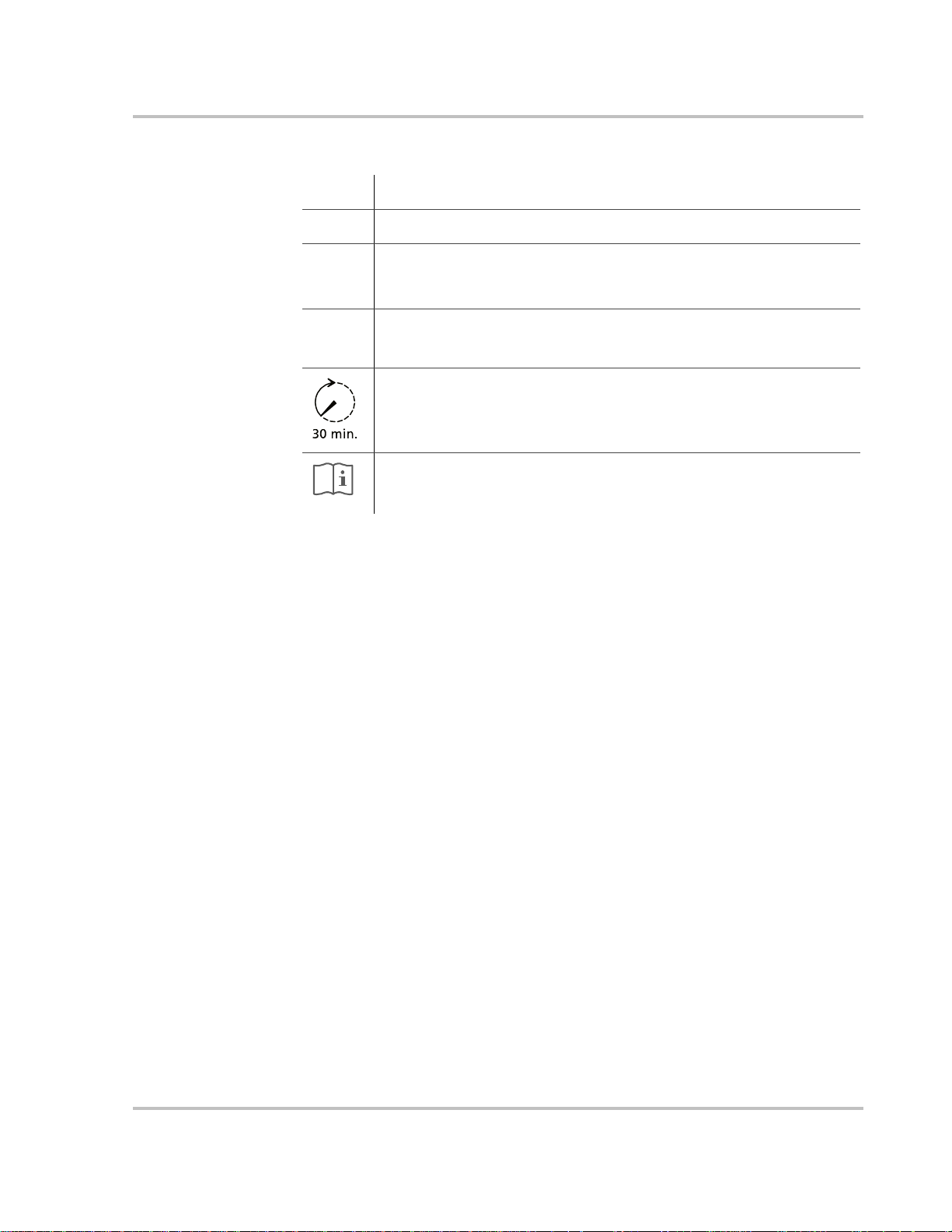
Symbols Used
About This Manual
!
"
#
$
Related Information
You can find more information about Xantrex Technology Inc. as well as its
products and services at www.xantrex.com
Alternating Current (AC)
Direct Current (DC)
In this guide: Important information, warnings, or cautions.
On the product: Important information, warnings or cautions with furth e r
explanation in the product guide.
Caution, risk of electric shock.
FOR AUTHORIZED SERVICE PERSONNEL: Before opening cover,
disconnect DC and AC power and wait 30 minutes to allow internal voltages
to reach safe levels.
NOTE: there are no user-serviceable parts inside.
Refer to the operating instructions.
975-0197-01-01 v

vi

Important Safety Instructions
SAVE THESE INSTRUCTIONS—This manual contains important instructions that shall be followed
during the installation and maintenance of the Xantrex Grid Tie Solar Inverter.
1. Before installing and using the GT Inverter, read all instructions and cautionary markings on the
inverter and in all appropriate sections of this guide.
2. To reduce risk of fire hazard, do not cover or obstruct the heat sink.
3. Observe the clearance recommendations as described on page 2–12. Do not install the G T In verter in a
zero-clearance or non-ventilated compartment. Overheating may result.
4. Use only accessories recommended or sold by the manufacturer. Doing otherwise may result in a risk
of fire, electric shock, or injury to persons.
5. To avoid a risk of fire and electric shock, make sure that existing wiring is in good condition and that
wire is not undersized. Do not operate the GT Inverter with damaged or substandard wiring.
6. Do not operate the G T Inverter if it has received a sharp blow, been dropped, or otherwise damaged in
any way. If the GT Inverter is damaged, see the Warranty section.
7. Do not disassemble the G T Inverter. It contains no user -serviceable parts. See Warranty for instructions
on obtaining service. Attempting to service the GT Inverter yourself may result in a risk of electrical
shock or fire and will void the factory warranty.
8. To reduce the risk of electrical shock, disconnect both AC and DC power from the GT Inverter before
attempting any maintenance or cleaning or working on any circuits connected to the inverter. Turning
off controls will not reduce this risk. Internal capacitors remain charged for up to 30 minutes after
disconnecting all sources of power.
9. The GT Inverter must be provided with an equipment-grounding conductor connected to the AC
ground.
975-0197-01-01 vii

Safety
Regulatory Compliance
The GT3.0-SP-QC-230 and GT3.0-DE-QC-230 are CE Marked for the following Directives and standards:
• Low Voltage Directive 73/23/EEC, per EN50178 “Electronic Equipment for Use in Power
Installations”.
• EMC Directive 89/336/EEC, per:
• EN61000-6-3 “Emission Standard for Residential, Commercial, and Light-Industrial
Environments”
• EN61000-6-1 “Immunity for Residential, Commercial, and Light-Industrial Environments”
• EN61000-3-2 “Limits for Harmonic Current Emissions”
• EN61000-3-3 “Limitations of Voltage Fluctuations and Flicker”.
The GT Inverter is designed for utility interactive operation. It has complete on-board over-current, overtemperature and anti-islanding protection. It monitors voltage and frequency of the utility grid and
automatically stops supplying power whenever conditions on the utility grid deviate from standard levels
(see Specifications).
The GT Inverter is equipped with a high frequency transformer that assures galvanic isolation between the
DC side and the utility power grid.
In Germany, an external device such as the UfE ENS26 is required to comply with VDE0126.
In Spain, an external ground fault detection device is required to make the photovoltaic installation fully
compliant with RD1663/2000.
viii 975-0197-01-01

Contents
Important Safety Instructions
Regulatory Compliance - - - - - - - - - - - - - - - - - - - - - - - - - - - - - - - - - - - - - - - - - - - - - - - - - - viii
1
Introduction
About the Xantrex Grid Tie Solar Inverter- - - - - - - - - - - - - - - - - - - - - - - - - - - - - - - - - - - - - - 1–2
Standard Features - - - - - - - - - - - - - - - - - - - - - - - - - - - - - - - - - - - - - - - - - - - - - - - - - - - - 1–3
Safety and Standards - - - - - - - - - - - - - - - - - - - - - - - - - - - - - - - - - - - - - - - - - - - - - - - - - 1–4
Model Configurations - - - - - - - - - - - - - - - - - - - - - - - - - - - - - - - - - - - - - - - - - - - - - - - - - - - 1–4
2
Installation
Installation Options - - - - - - - - - - - - - - - - - - - - - - - - - - - - - - - - - - - - - - - - - - - - - - - - - - - - - 2–2
Single Inverter Installation - - - - - - - - - - - - - - - - - - - - - - - - - - - - - - - - - - - - - - - - - - - - - - 2–2
Multiple Inverter Installations - - - - - - - - - - - - - - - - - - - - - - - - - - - - - - - - - - - - - - - - - - - 2–2
Planning the Installation - - - - - - - - - - - - - - - - - - - - - - - - - - - - - - - - - - - - - - - - - - - - - - - - - - 2–2
Inverter Location - - - - - - - - - - - - - - - - - - - - - - - - - - - - - - - - - - - - - - - - - - - - - - - - - - - - 2–4
PV Array Requirements - - - - - - - - - - - - - - - - - - - - - - - - - - - - - - - - - - - - - - - - - - - - - - - 2–5
Grounding Requirements - - - - - - - - - - - - - - - - - - - - - - - - - - - - - - - - - - - - - - - - - - - - - - - 2–7
Routing the Wires - - - - - - - - - - - - - - - - - - - - - - - - - - - - - - - - - - - - - - - - - - - - - - - - - - - 2–8
Preparing for the Installation - - - - - - - - - - - - - - - - - - - - - - - - - - - - - - - - - - - - - - - - - - - - - - - 2–9
Wiring - - - - - - - - - - - - - - - - - - - - - - - - - - - - - - - - - - - - - - - - - - - - - - - - - - - - - - - - - - - 2–9
AC Circuit Breaker Requirements - - - - - - - - - - - - - - - - - - - - - - - - - - - - - - - - - - - - - - - - - 2–9
AC and DC Disconnects - - - - - - - - - - - - - - - - - - - - - - - - - - - - - - - - - - - - - - - - - - - - - - - 2–9
Mounting the Inverter - - - - - - - - - - - - - - - - - - - - - - - - - - - - - - - - - - - - - - - - - - - - - - - - - - 2–10
Overview - - - - - - - - - - - - - - - - - - - - - - - - - - - - - - - - - - - - - - - - - - - - - - - - - - - - - - - - 2–10
Tools and Materials Needed - - - - - - - - - - - - - - - - - - - - - - - - - - - - - - - - - - - - - - - - - - - - 2–11
Dimensions - - - - - - - - - - - - - - - - - - - - - - - - - - - - - - - - - - - - - - - - - - - - - - - - - - - - - - - 2–11
Installing the Mounting Bracket - - - - - - - - - - - - - - - - - - - - - - - - - - - - - - - - - - - - - - - - - 2–12
Mounting the Inverter on the Bracket - - - - - - - - - - - - - - - - - - - - - - - - - - - - - - - - - - - - - 2–16
- - - - - - - - - - - - - - - - - - - - - - - - - - - - - - - - - - - - - - - - - - -vii
3
Wiring the Inverter
Connecting the DC Wiring - - - - - - - - - - - - - - - - - - - - - - - - - - - - - - - - - - - - - - - - - - - - - - - - 3–2
Equipment Needed - - - - - - - - - - - - - - - - - - - - - - - - - - - - - - - - - - - - - - - - - - - - - - - - - - - 3–2
Connecting the PV Array - - - - - - - - - - - - - - - - - - - - - - - - - - - - - - - - - - - - - - - - - - - - - - 3–3
Connecting the AC Wiring - - - - - - - - - - - - - - - - - - - - - - - - - - - - - - - - - - - - - - - - - - - - - - - - 3–5
Making AC Connections Using Quick Connects - - - - - - - - - - - - - - - - - - - - - - - - - - - - - - - 3–5
Connecting Inverters in Parallel- - - - - - - - - - - - - - - - - - - - - - - - - - - - - - - - - - - - - - - - - - - - - 3–7
Communications Wiring for Inverters in Parallel - - - - - - - - - - - - - - - - - - - - - - - - - - - - - - - - - 3–8
975-0197-01-01 ix

Contents
Xanbus Network Technology - - - - - - - - - - - - - - - - - - - - - - - - - - - - - - - - - - - - - - - - - - - 3–8
Guidelines for Routing the Network Cables - - - - - - - - - - - - - - - - - - - - - - - - - - - - - - - - - -3–11
Connecting the Communications Cable between Inverters - - - - - - - - - - - - - - - - - - - - - - - -3–12
4
Starting the Inverter
Commissioning Procedure - - - - - - - - - - - - - - - - - - - - - - - - - - - - - - - - - - - - - - - - - - - - - - - - 4–2
Non-Islanding Test - - - - - - - - - - - - - - - - - - - - - - - - - - - - - - - - - - - - - - - - - - - - - - - - - - - - - 4–3
5
Monitoring the Inverter
Monitoring the Front Panel Display- - - - - - - - - - - - - - - - - - - - - - - - - - - - - - - - - - - - - - - - - - 5–2
Front Panel Display Screens and What They Mean - - - - - - - - - - - - - - - - - - - - - - - - - - - - - - - 5–3
Startup Mode - - - - - - - - - - - - - - - - - - - - - - - - - - - - - - - - - - - - - - - - - - - - - - - - - - - - - - 5–3
Normal Operation Mode - - - - - - - - - - - - - - - - - - - - - - - - - - - - - - - - - - - - - - - - - - - - - - 5–3
Offline Mode - - - - - - - - - - - - - - - - - - - - - - - - - - - - - - - - - - - - - - - - - - - - - - - - - - - - - - 5–5
Fault Mode - - - - - - - - - - - - - - - - - - - - - - - - - - - - - - - - - - - - - - - - - - - - - - - - - - - - - - - - 5–7
Special Screens - - - - - - - - - - - - - - - - - - - - - - - - - - - - - - - - - - - - - - - - - - - - - - - - - - - - - 5–8
Custom Screens - - - - - - - - - - - - - - - - - - - - - - - - - - - - - - - - - - - - - - - - - - - - - - - - - - - - 5–9
Status Indicator Lights- - - - - - - - - - - - - - - - - - - - - - - - - - - - - - - - - - - - - - - - - - - - - - - - - - -5–10
6
Maintenance and Troubleshooting
Factors Affecting GT Inverter Performance - - - - - - - - - - - - - - - - - - - - - - - - - - - - - - - - - - - - 6–2
PV Array Factors - - - - - - - - - - - - - - - - - - - - - - - - - - - - - - - - - - - - - - - - - - - - - - - - - - - 6–2
Other Factors - - - - - - - - - - - - - - - - - - - - - - - - - - - - - - - - - - - - - - - - - - - - - - - - - - - - - - 6–3
Performing General Maintenance - - - - - - - - - - - - - - - - - - - - - - - - - - - - - - - - - - - - - - - - - - - 6–3
Identifying Error/Fault Conditions and Solutions- - - - - - - - - - - - - - - - - - - - - - - - - - - - - - - - - 6–4
A
Specifications
Electrical Specifications - - - - - - - - - - - - - - - - - - - - - - - - - - - - - - - - - - - - - - - - - - - - - - - - - A–2
Input - - - - - - - - - - - - - - - - - - - - - - - - - - - - - - - - - - - - - - - - - - - - - - - - - - - - - - - - - - - - A–2
Output - - - - - - - - - - - - - - - - - - - - - - - - - - - - - - - - - - - - - - - - - - - - - - - - - - - - - - - - - - - A–2
Adjustable Disconnect Settings - - - - - - - - - - - - - - - - - - - - - - - - - - - - - - - - - - - - - - - - - - A–3
Efficiency - - - - - - - - - - - - - - - - - - - - - - - - - - - - - - - - - - - - - - - - - - - - - - - - - - - - - - - - A–4
Environmental Specifications- - - - - - - - - - - - - - - - - - - - - - - - - - - - - - - - - - - - - - - - - - - - - - A–5
User Display - - - - - - - - - - - - - - - - - - - - - - - - - - - - - - - - - - - - - - - - - - - - - - - - - - - - - - A–5
Mechanical Specifications - - - - - - - - - - - - - - - - - - - - - - - - - - - - - - - - - - - - - - - - - - - - - - - - A–5
Warranty and Return Information
Index
- - - - - - - - - - - - - - - - - - - - - - - - - - - - - - - - - - - - - - - - - - - - - - - - - - - - - - - - - - - - - - - IX–1
- - - - - - - - - - - - - - - - - - - - - - - - - - - - - - - - - - - WA–1
x 975-0197-01-01

Figures
Figure 1-1 Basic System Overview - - - - - - - - - - - - - - - - - - - - - - - - - - - - - - - - - - - - - - - - - - - - 1–2
Figure 1-2 Main Features of the GT Inverter- - - - - - - - - - - - - - - - - - - - - - - - - - - - - - - - - - - - - - 1–3
Figure 2-1 Installation Options Overview- - - - - - - - - - - - - - - - - - - - - - - - - - - - - - - - - - - - - - - - 2–3
Figure 2-2 Installation Overview- - - - - - - - - - - - - - - - - - - - - - - - - - - - - - - - - - - - - - - - - - - - - 2–10
Figure 2-3 GT Inverter Dimensions- - - - - - - - - - - - - - - - - - - - - - - - - - - - - - - - - - - - - - - - - - - 2–11
Figure 2-4 Mounting Bracket and GT Inverter - - - - - - - - - - - - - - - - - - - - - - - - - - - - - - - - - - - 2–12
Figure 2-5 Examples of Mounting on a Pole or Rails - - - - - - - - - - - - - - - - - - - - - - - - - - - - - - - 2–14
Figure 2-6 Installing the Mounting Bracket using Plywood Support - - - - - - - - - - - - - - - - - - - - - 2–15
Figure 2-7 Proper Placement of the Inverter on the Mounting Bracket - - - - - - - - - - - - - - - - - - - 2–16
Figure 3-1 PV Quick Connect Location - - - - - - - - - - - - - - - - - - - - - - - - - - - - - - - - - - - - - - - - - 3–2
Figure 3-2 DC Connections for a Two-String PV Array - - - - - - - - - - - - - - - - - - - - - - - - - - - - - - 3–4
Figure 3-3 AC Connector (female) - - - - - - - - - - - - - - - - - - - - - - - - - - - - - - - - - - - - - - - - - - - - 3–6
Figure 3-4 Improper multiple inverter connections- - - - - - - - - - - - - - - - - - - - - - - - - - - - - - - - - - 3–7
Figure 3-5 Daisy Chain Layout- - - - - - - - - - - - - - - - - - - - - - - - - - - - - - - - - - - - - - - - - - - - - - -3–8
Figure 3-6 Male Network Terminator - - - - - - - - - - - - - - - - - - - - - - - - - - - - - - - - - - - - - - - - - - 3–9
Figure 3-7 Location of Xanbus RJ45 Ports - - - - - - - - - - - - - - - - - - - - - - - - - - - - - - - - - - - - - - - 3–9
Figure 3-8 RJ45 Connector - - - - - - - - - - - - - - - - - - - - - - - - - - - - - - - - - - - - - - - - - - - - - - - - 3–10
Figure 5-1 Front Panel LCD Location - - - - - - - - - - - - - - - - - - - - - - - - - - - - - - - - - - - - - - - - - - 5–2
Figure 5-2 Location of Status Indicator Lights - - - - - - - - - - - - - - - - - - - - - - - - - - - - - - - - - - - 5–10
Figure A-1 Output Power vs. Ambient Temperature - - - - - - - - - - - - - - - - - - - - - - - - - - - - - - - - -A–3
Figure A-2 Typical Efficiency- - - - - - - - - - - - - - - - - - - - - - - - - - - - - - - - - - - - - - - - - - - - - - - -A–4
975-0197-01-01 xi

xii

Tables
Table 1-1 GT Inverter Models- - - - - - - - - - - - - - - - - - - - - - - - - - - - - - - - - - - - - - - - - - - - - - - 1–4
Table 2-1 MPPT Operational Window - - - - - - - - - - - - - - - - - - - - - - - - - - - - - - - - - - - - - - - - - 2–6
Table 2-2 Inverter Clearance Requirements- - - - - - - - - - - - - - - - - - - - - - - - - - - - - - - - - - - - - 2–12
Table 3-1 T568A Standard Wiring- - - - - - - - - - - - - - - - - - - - - - - - - - - - - - - - - - - - - - - - - - - 3–10
Table 3-2 Network Components and Part Numbers- - - - - - - - - - - - - - - - - - - - - - - - - - - - - - - - 3–11
Table 5-1 Startup Screens on GT Inverter Front Panel Display - - - - - - - - - - - - - - - - - - - - - - - - - 5–3
Table 5-2 Normal Operation Default Screen - - - - - - - - - - - - - - - - - - - - - - - - - - - - - - - - - - - - - 5–4
Table 5-3 Normal Operation Screens for All GT Inverters - - - - - - - - - - - - - - - - - - - - - - - - - - - - 5–4
Table 5-4 Additional Normal Operation Screens for Each GT Inverter in a Multiple Unit System - 5–5
Table 5-5 Offline Mode Default Display- - - - - - - - - - - - - - - - - - - - - - - - - - - - - - - - - - - - - - - - 5–5
Table 5-6 Offline Mode Screens for All GT Inverters - - - - - - - - - - - - - - - - - - - - - - - - - - - - - - - 5–6
Table 5-7 Additional Offline Mode Screens for Each GT Inverter in a Multiple Unit System - - - - 5–6
Table 5-8 Fault Message Screens- - - - - - - - - - - - - - - - - - - - - - - - - - - - - - - - - - - - - - - - - - - - - 5–7
Table 5-9 Additional Fault Mode Screens - - - - - - - - - - - - - - - - - - - - - - - - - - - - - - - - - - - - - - - 5–8
Table 5-10 Special Message Screens - - - - - - - - - - - - - - - - - - - - - - - - - - - - - - - - - - - - - - - - - - - 5–8
Table 5-11 Status Indicator LEDs - - - - - - - - - - - - - - - - - - - - - - - - - - - - - - - - - - - - - - - - - - - - 5–10
Table 6-1 Troubleshooting the GT Inverter - - - - - - - - - - - - - - - - - - - - - - - - - - - - - - - - - - - - - - 6–4
975-0197-01-01 xiii

xiv

1
Introduction
Chapter 1, “Introduction”, contains information about the features
and functions of the Xantrex Grid Tie Solar Inverter.
The topics in this chapter are organized as follows.
“About the Xantrex Grid Tie Solar Inverter”:
• “Standard Features” on page 1–3
• “Safety and Standards” on page 1–4
“Model Configurations”.
Introduction
About the Xantrex Grid Tie Solar Inverter
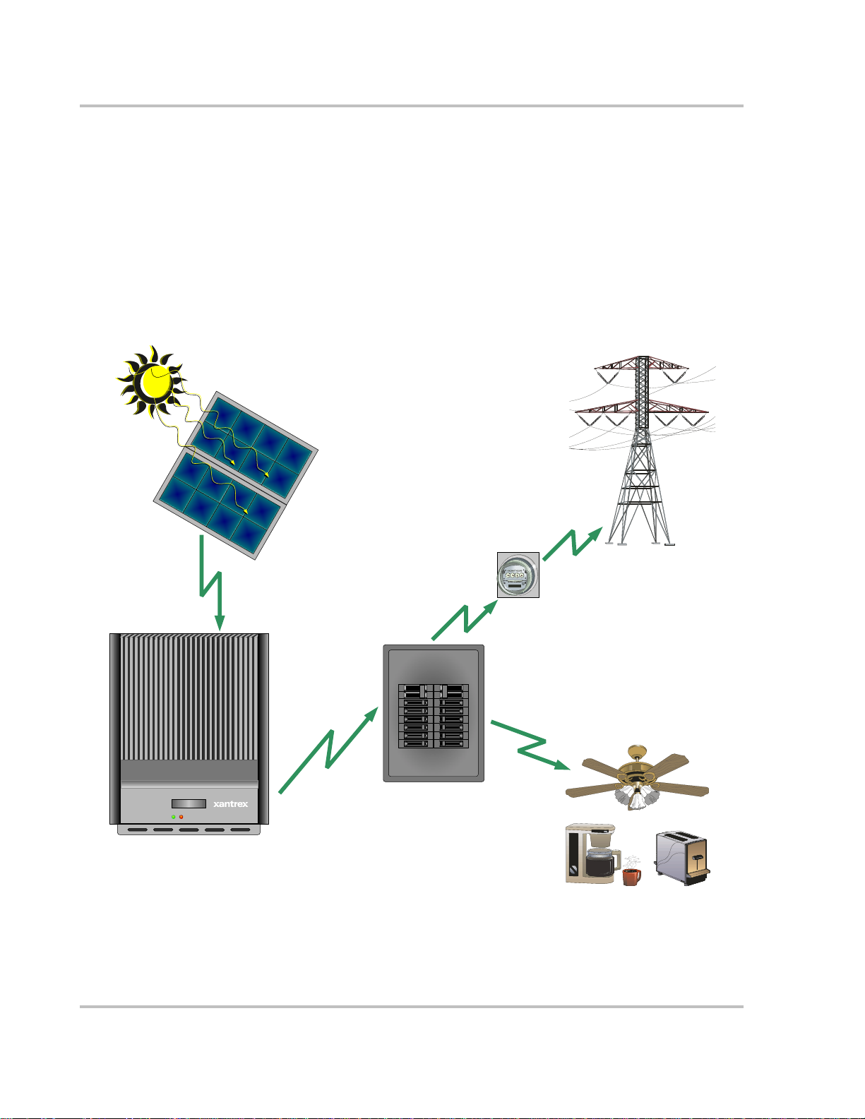
The Xantrex Grid Tie Solar Inverter (GT Inverter) is designed to convert solar
electric (photovoltaic or PV) power into utility-grade electricity that can be used
by the home or sold to the local power company.
Installing the GT Inverter consists of mounting it to the wall and connecting the
DC input to a PV array and the AC output to the utility. See Figure 1-1 for a
simple diagram of a typical installation.
In order to operate, the GT Inverter must have grid power available and connected.
It will not provide backup power if the AC grid fails.
Photovoltaic (PV) Panels—
P hotovoltaic (P V)
PV Array
Panel s – PV Ar ray
Harvested sol ar
energy
Harvested solar energy
DC converted to AC
Grid Tie Solar Inverter
Xantrex GT Inverter
X antrex GT Inverte r
Figure 1-1 Basic System Overview
DC conv erted to
AC
Main Utility Service Panel
Main Utility
Ser vi ce Panel
Surplus power routed
Utility
to Utility Grid
Meter
Utility Meter
Surplus power routed to
Power routed t o loads
Power routed to loads
Utility Grid
Utility Grid
Utility Grid
Loads
Loads
1–2 975-0197-01-01
About the Xantrex Grid Tie Solar Inverter
PV compatibility The G T Invert er is designed to take advantage of solar modules configured as high
voltage PV string arrays—single crystalline, poly crystalline, or thin film—with a
195 to 550 Vdc input voltage Maximum Power Point range.
Maximum Power
Point Tracking
(MPPT)
The GT Inverter uses Xantrex proprietary Maximum Power Point Tracking
(MPPT) technology to harvest the maximum amount of energy from the solar
array. MPPT learns your array’s specific characteristics, maximizing its output at
all times.
High efficiency The high-frequency, solid-state design of the GT Inverter is extremely efficient—
up to 95%.
Expandable Multiple GT Inverters may be connected in a parallel configuration for increased
net metering capacity or future system growth.
Communications
protocol
The GT Inverter uses the Xanbus
communicate with other units connected in parallel within the system. For more
®
Communications protocol, enabling it to
information, see “Xanbus Network Technology” on page 3–8.
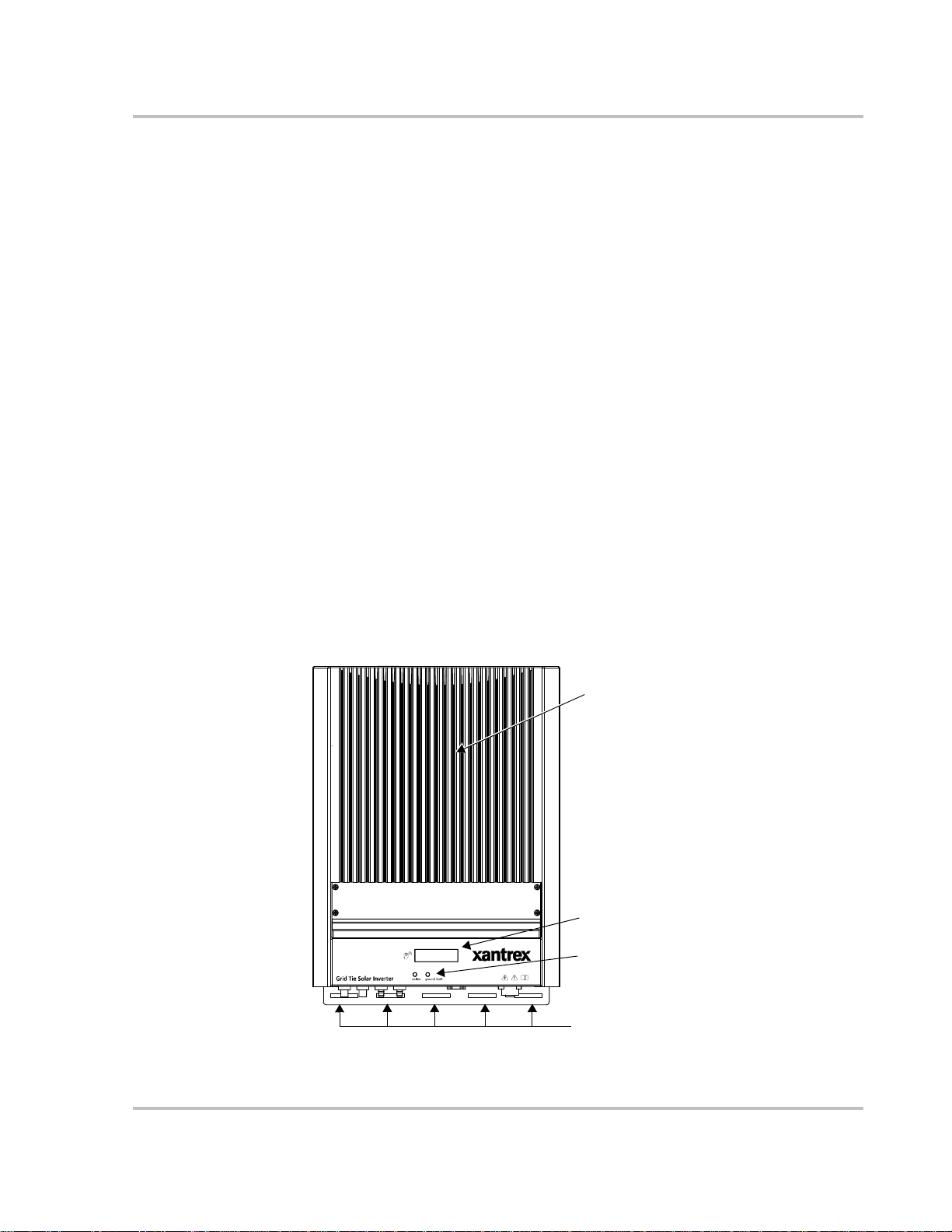
Standard Features
The GT Inverter has the following standard features:
• Sealed inverter section with multiple wiring options to facilitate a variety of
installation requirements (e.g., hard-wired or with “quick connects”);
• Liquid Crystal Display (LCD) to provide easy-to-read system status and daily
cumulative energy production information;
• Two LED indicator lights to provide status and ground fault indication.
Heat Sink
LCD
LED Indicator Lights
Mounting Slots
Figure 1-2
975-0197-01-01 1–3
Main Features of the GT Inverter
Introduction
Safety and Standards
Meets standards and
requirements
The GT Inverter has complete on-board over-current, over-temperature and antiislanding protections. GT Inverter models GT3.0-SP-QC-230 and GT3.0-DE-QC230 are CE Marked per Low Voltage Directive 73/23/EEC (EN50178) and EMC
Directive 89/336/EEC (EN61000-6-3, EN61000-6-1, EN61000-3-2, EN61000-3-
3).
Model Configurations
The GT Inverter model number is in the format GTx.x-aa-bb-ccc, where:
• x.x Output Power: 3.0 KW
• aa Region: NA (North America)
• bb Wiring Box: DS (wiring box with AC/DC disconnect switch,
• ccc Output Voltage: 208 Vac/60 Hz (North America)
Table 1-1 shows the different model configurations available.
DE (Germany)
SP (Spain)
North American models only)
QC (Quick Connects and no wiring box, Europe
only)
230 Vac/50 Hz (Europe)
240 Vac/60 Hz (North America).
Table 1-1
Model Number
GT3.0-NA-bb-208
GT3.0-aa2-bb-230
GT3.0-NA-bb-240
1. 208 Vac/60 Hz model not available at this time
2. any region (aa) except NA
GT Inverter Models
Output P ower
(x.x)
1
3.0
Output Voltage
(ccc)
208
230
240
Wiring Box (bb)
DS QC
√
√
√
Installation and wiring instructions are provided in Chapter 2, “Installation”, and
Chapter 3, “Wiring the Inverter”.
1–4 975-0197-01-01

2
Installation
Chapter 2, “Installation”, provides information about planning for and
installing the GT Inverter. It contains information to help you plan
wire routes, ensure your PV array provides necessary power, and find
a suitable location for installation.
The topics in this chapter are organized as follows:
• “Installation Options” on page 2–2
• “Planning the Installation” on page 2–2
• “Preparing for the Installation” on page 2–9
• “Mounting the Inverter” on page 2–10.

Installation
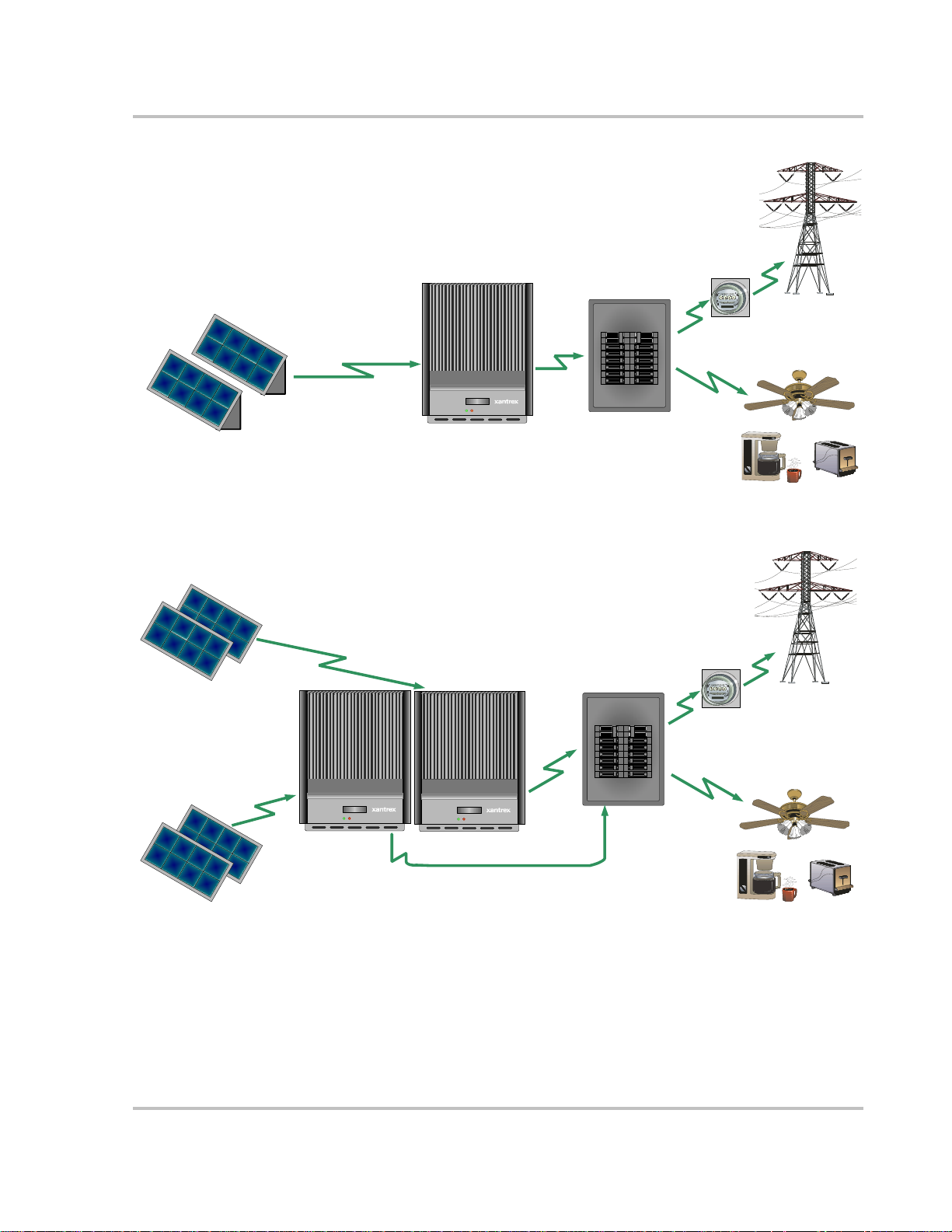
Installation Options
The GT Inverter may be installed as a single inverter for a single PV array of one
or two PV strings, or in a multiple inverter configuration for multiple PV arrays
(see Figure 2-1 for diagrams of both options).
Single Inverter Installation
In this configuration, a single inverter collects the harvested solar energy and
routes the power to the main utility service panel to be used by the loads. Any
surplus power not used by the loads will be injected into the utility grid.
Multiple Inverter Installations
If multiple inverters are used, each inverter must be wired to an independent PV
array . In this configuration, each inverter collects the harvested solar energy from
a separate PV array and routes the power to the main utility service panel to be
used by the loads. Any surplus power not used by the loads will be injected into
the utility grid.
Communications between inverters is optional, but can be enabled by installing
communications cabling to the inverter RJ45 ports. See “Connecting the
Communications Cable between Inverters” on page 3–12.
Planning the Installation
The following issues need to be considered when planning for an installation
using the GT Inverter. See the specified sections for more information.
• “Inverter Location” on page 2–4
• “PV Array Requirements” on page 2–5
• “Grounding Requirements” on page 2–7
• “Routing the Wires” on page 2–8.
Ensure that you have obtained all permits required by local authorities or utilities
before commencing installation.
2–2 975-0197-01-01
Utility Gr i d
P hotovoltaic Pa nels - PV A rray
PV String #1
PV String #2
Photovoltaic (PV) Panels—
PV Array
Harvested solar energy
Harvested solar energy
Single Inverter Installation
Xantrex
GT Inver t er
DC converted
to AC
DC converted
Grid Tie Solar Inverter
to AC
Xantrex GT Inverter
M ain Utility Se rv ice
Panel
Main Utility
Service Panel
Planning the Installation
Surplus power routed
Utility
to Utility Grid
Meter
Surpl us power routed to
Utility Meter
Power routed to loads
Power routed to loads
Loads
Utility Grid
Utility Grid
Loads
PV Array #2
PV Ar r ay #1
P hotovoltaic Pa nels:
M u ltip le PV Arra y s
Photovoltaic Panels—
Multiple PV Arrays
Harvested sol ar energy
Harvested
solar energy
PV Ar r ay #2
Figure 2-1
Installation Options Overview
Harvested solar energy
Har vested solar
energy
Grid Tie Solar Inverter
GT Inverter #1
PV Array #1
X a n trex GT Inve rters
GT Inver t er #1
Multiple Inverter Installation
DC converted
to AC
DC convert ed
to AC
Grid Tie Solar Inverter
G T Invert er #2
GT Inverter #2
DC converted to AC
DC converted to AC
M ain Utility Serv ice
Panel
Main Utility
Power routed to loads
Service Panel
Surplus power routed
Utility
to Utility Grid
Meter
Utility Meter
Power routed to loads
Loads
Utility Grid
Utility Grid
Surplus power routed to
Utility Grid
Loads
975-0197-01-01 2–3

Installation
Inverter Location
WARNING: Burn hazard
Do not install in a location where people can accidentally come into contact with the front
of the inverter. High temperatures can be present on the face of the inverter, causing a
potential burn hazard.
In extreme conditions, the GT Inverter chassis can reach temperatures that can cause skin
burns if accidentally touched. Ensure that the GT Inverter is located away from normal
traffic areas.
Inverter failure due to improper installation will void the inverter warranty.
Consider the following when determining where to install the inverter.
Fire Safety
Indoor/
Outdoor
Orientation
Temperature
Ground
Clearance
Distance
• Do not install anywhere near combustible or flammable materials.
• The GT Inverter can be mounted indoors or outdoors. When installed
outdoors, the GT Inverter must be mounted in a vertical orientation.
• In outdoor installations the GT Inverter should be located away from
lawn sprinklers and other sources of spray.
• The GT Inverter must be mounted vertically on a wall or pole.
• Do not mount the GT Inverter horizont ally.
• Ensure that the GT Inverter is mounted in a location where the
ambient temperature range is -25 to 65 °C (-13 to 149 °F).
• At extreme hot or cold temperatures, the front panel LCD may not
function normally. Above 45 °C (113 °F), the unit begins derating
power. See “Environmental Specifications” on page A–5 and “Output
Power vs. Ambient Temperature” on page A–3.
• Outdoors, the GT Inverter requires at least 100 cm (39 inches) of
clearance between the bottom of the unit and the ground. This
clearance helps prevent water from splashing onto the bottom of the
unit.
• Indoors, it is recommended to use the same clearance to ensure
visibility of the LCD.
• To minimize copper losses, ensure that wire lengths between the PV
array and the GT Inverter and between the inverter and the Main
Utility Service Panel are kept to a minimum.
• Maximum distances will depend on wire gauges used and PV array
output voltages.
Debris free
2–4 975-0197-01-01
• Excessive debris (such as dust, leaves, and cobwebs) can accumulate
on the unit, interfering with wiring connections and ventilation. Do
not install in a location where debris can accumulate (such as under a
tree).

PV Array Requirements
WARNING: Shock hazard
Whenever a PV array is exposed to sunlight, a shock hazard exists at the output wires or
exposed terminals. To reduce the risk of shock during installation, cover the array with an
opaque (dark) material before making any connections.
General Recommendations
It is important that the PV array is installed correctly to the manufacturer’s
specifications and to local code requirements.
Equipment and Installation Recommendations
Planning the Installation
Equipment
recommendations
Installation
recommendations
Important:
small obstructions such as vent pipes, chimneys and power lines. A small amount of shade
can have a disproportionately high impact on system performance.
• All electrical equipment should be approved for the voltage and current
ratings necessary for the application.
• All wiring should be sized correctly to minimize voltage drop.
• All exposed wires or conduits should be sunlight resistant.
• All required overcurrent protections should be included in the system and
accessible for maintenance.
• All electrical terminations should be fully tightened, secured, and strain
relieved as appropriate.
• All mounting equipment should be installed according to the manufacturer’s
specifications.
• All wires, conduit, exposed conductors and electrical boxes should be secured
and supported according to code requirements.
The PV array should be free of shade. This requirement includes even
975-0197-01-01 2–5
 Loading...