

Page 1
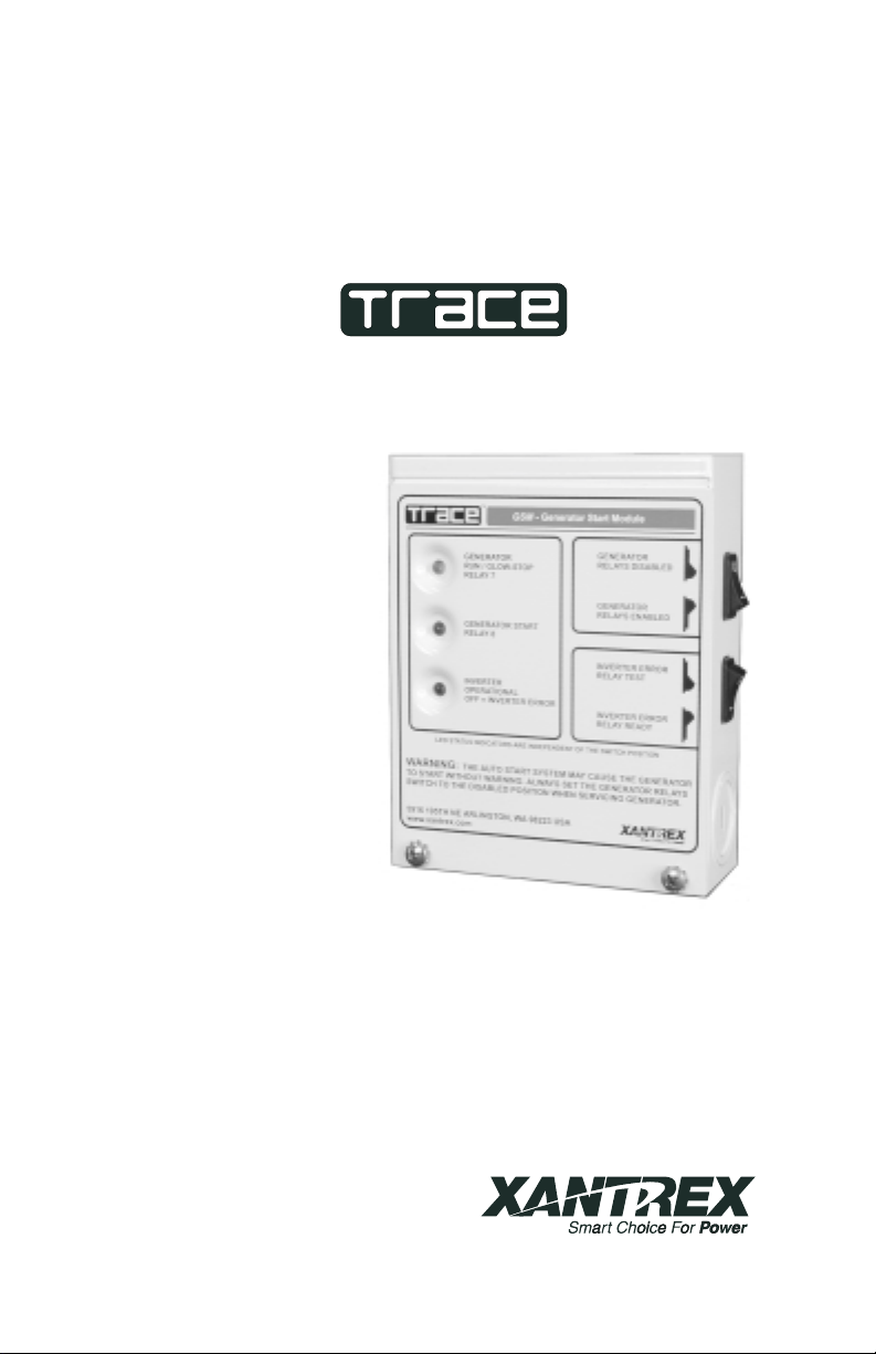
GSM
Generator Start Module
Installation and Operation Guide
ã2001 Xantrex Technology Inc. P/N 975-0008-01-02 Rev. A 01/01
Page 2

Page 3

GSMGenerator Start Module
Table of Contents
1.0 INTRODUCTION ................................................................. 1
Unpacking and Inspection ............................................................................. 1
Controls and Indicators ................................................................................. 2
Indicator LEDs ....................................................................................... 2
GENERATOR RUN/GLOWSTOP RELAY 7 LED ......................... 2
GENERATOR START RELAY 8 LED ........................................... 2
INVERTER OPERATIONAL LED ................................................. 2
Switches ................................................................................................ 3
GENERATOR START Switch ....................................................... 3
Internal Components ..................................................................................... 4
INVERTER ERROR Switch .......................................................... 3
Relays .................................................................................................... 4
Relay Terminal Block ............................................................................. 4
Ground Stud .......................................................................................... 4
Fuses ..................................................................................................... 4
2.0 INSTALLATION ................................................................... 6
Tools Required............................................................................................... 6
Pre-Installation .............................................................................................. 6
Mounting Procedure ...................................................................................... 6
Generator Wiring ........................................................................................... 9
To connect the generator wires to the terminal block ........................... 9
Two-Wire Start Circuits ....................................................................... 10
Wiring Honda-Type Generators .......................................................... 11
Wiring Onan-Type Generators ............................................................ 12
Error Indicator Wiring .................................................................................. 13
Communication Cable ................................................................................. 14
3.0 OPERATION ...................................................................... 15
Operation and Test ...................................................................................... 15
Internal Sticker .................................................................................... 16
Danger Label ....................................................................................... 16
4.0 TROUBLESHOOTING ...................................................... 17
5.0 SERVICE INFORMATION .................................................. 18
6.0 WARRANTY ...................................................................... 19
7.0 SPECIFICATIONS.............................................................. 20
©2001 Xantrex Technology Inc. i
Page 4
IMPORTANT SAFETY INSTRUCTIONS
This manual contains important safety instructions that should be followed
during the installation and maintenance of this product.
To reduce the risk of electrical shock, and to ensure the safe installation
and operation of this product, the following safety symbols have been placed
throughout this manual to indicate dangerous conditions and important safety
instructions.
WARNING - A dangerous voltage or condition exists in this area.
Use extreme caution when performing these tasks.
AVERTISSEMENT - Une tension ou condition dangereuse existe
dans cette zone. Faire preuve dextrême prudence lors de la
réalisation de ces tâches.
CAUTION - This procedure is critical to the safe installation or
operation of the unit. Follow these instructions closely.
ATTENTION - Cette procédure est essentielle à linstallation ou
lutilisation de lunité en toute sécurité. Suivre ces instructions
deprès.
NOTE - This statement is important. Follow instructions closely.
NOTE - Cette déclaration est importante. Suivre les instructions
deprès.
All electrical work must be done in accordance with local, national,
and/or international electrical codes.
Before installing or using this device, read all instructions and cautionary
markings located in the manual and on the generator.
Do not expose this unit to rain, snow or liquids of any type. This product is
designed only for indoor mounting.
To reduce the chance of short-circuits, use insulated tools when installing
or working with this product, the inverter, the batteries or generator.
Remove all jewelry such as rings, bracelets, necklaces, etc., while installing
the GSM. This will greatly reduce the chance of accidental exposure to live
circuits.
The inverter contains more than one live circuit (batteries, PV array, AC
line, etc.). Power may be present at more than one source.
To reduce risk of electric shock, disconnect all wiring before attempting any
maintenance or cleaning. Turning off the device may not reduce this risk.
Disable the generators starting circuit by disconnecting the starter battery,
spark plug, etc., before wiring this device.
SAVE THESE INSTRUCTIONS
ii ©2001 Xantrex Technology Inc.
Page 5

Disclaimer of Liability
Since the use of this manual and the conditions or methods of installation,
operation, use and maintenance of the unit are beyond the control of Xantrex
Technology Inc., the company does not assume responsibility and expressly
disclaims liability for loss, damage, or expense arising out of or any way
connected with such installation, operation, use, or maintenance.
©2001 Xantrex Technology Inc. iii
Page 6

NOTE: Due to continual improvement through product updates,
photographs and/or illustrations used in this manual may not exactly
match your unit. Xantrex Technology Inc., reserves the right to
update this product without notice or releasing an updated manual
when fit, form or function are not affected.
iv ©2001 Xantrex Technology Inc.
Page 7
1.0 INTRODUCTION
The GSM (Generator Start Module) is an accessory for selected Trace
inverter/charger models allowing automatic generator control and inverter error
indication when using the optional SWRC remote control. The unit contains
three relays providing normally open (N.O.), normally closed (N.C.) and
common (COM) contacts. Relays RY7 and RY8 are used for generator
control. Relay RY11 is used to indicate an error condition (via an external
indicator) whenever the inverters output is shutdown. This could be a bell,
buzzer, light, etc.
The unit interfaces the inverter (via a phone type cable) to an auto-start/
stop generator. Commands from the inverter control the generator when
defined parameters (programmed via the SWRC or SWCA for PS Series
models) are met. Refer to the inverter operators manual for setting the
various parameters for generator operation.
Front panel LEDs provide a visual display of relay activity whenever a
relay contact receives an engage command from the inverter. A highly visible
blue LED indicates the inverter is operational.
Unpacking and Inspection
Carefully inspect the contents of the shipping carton for damages. Report
any damages to the carrier immediately.
The following items are packed with the GSM:
Generator Start Module unit (GSM)
25-foot cable
Operators manual
Generator Danger Label
Report any missing items to Xantrex Technology Inc., immediately.
Generator Start Module (GSM)
©2001 Xantrex Technology Inc. 1
Figure 1
Page 8
1.0 INTRODUCTION
Controls and Indicators
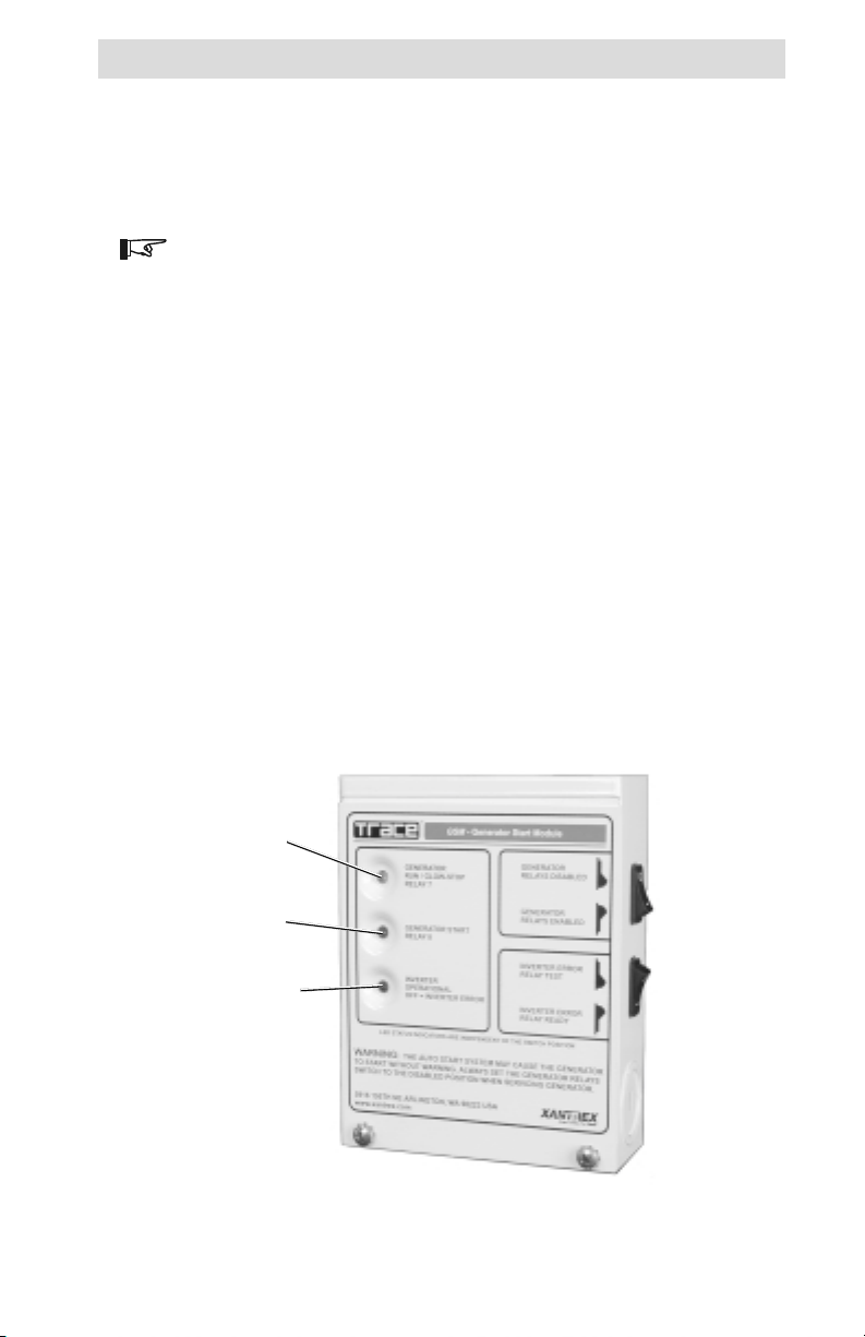
Indicator LEDs
Three LEDs located on the front panel of the GSM indicate the relay
control signal status from the inverter.
NOTE: The LEDs are unaffected by the GSMs switch positions or
fuse condition.
GENERATOR RUN/GLOWSTOP RELAY 7 LED
The yellow LED indicates relay RY7 is receiving a control signal to
engage the relay and RUN the generator or provide a GLOWSTOP signal
(for diesel generators). The LED turns ON when the relays COM and N.O.
contacts engage. The function of this relay is dependent on the selection
made (using the SWRC) as to whether it is used to RUN the generator or
provide GLOWSTOP control.
GENERATOR START RELAY 8 LED
The green LED indicates relay RY8 is receiving a START signal from the
inverter. The LED turns ON when the relays COM and N.O. contacts
engage.
INVERTER OPERATIONAL LED
The blue LED indicates the inverters operational status. If the inverter is
powered and ready for operation, the blue SYSTEM OPERATIONAL LED
turns ON as soon as the phone-type cable is plugged into the inverter. If
the blue LED does not turn ON, the inverter is either not powered, is set to
the CHG only mode without any utility pass-through, or has no AC output
which may be caused by an error condition.
Yellow LED
RUN/GLOWSTOP
RELAY 7
Green LED
GENERATOR START
RELAY 8
Blue LED
INVERTER OPERATIONAL
OFF = INVERTER ERROR
Figure 2
Indicator LEDs
2 ©2001 Xantrex Technology Inc.
Page 9
1.0 INTRODUCTION
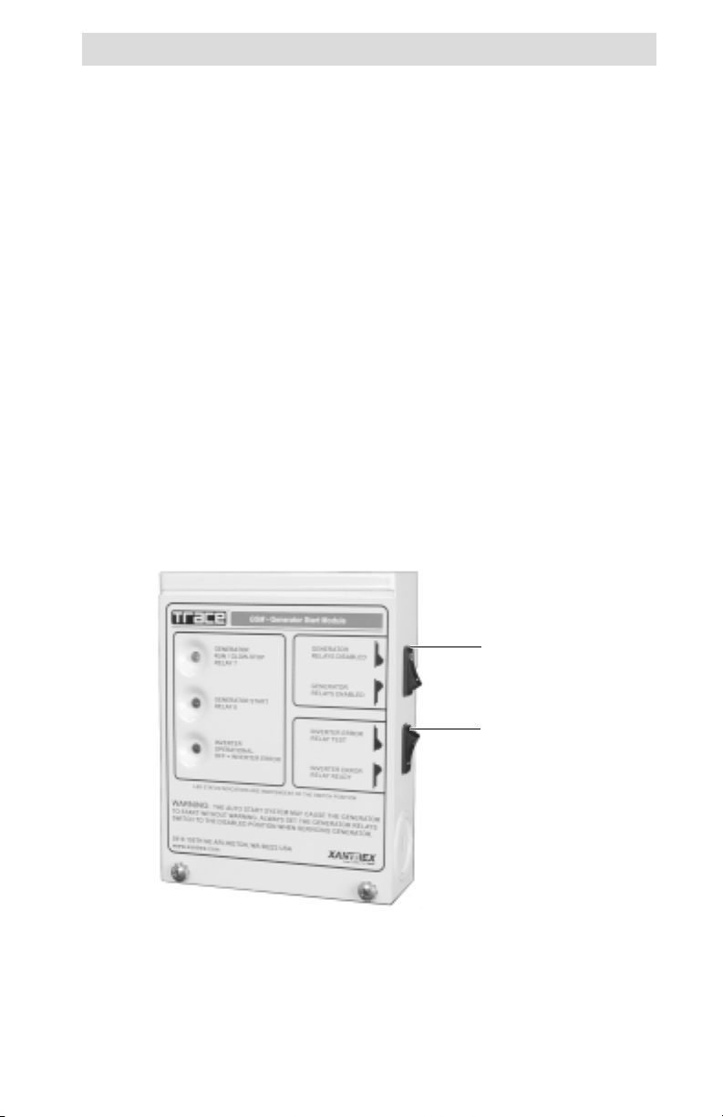
Controls and Indicators (continued)
Switches
Two switches are provided on the right side of the GSM to effectively
disconnect the relay coils from the inverters supply voltage (11 VDC), thus
preventing the relays from engaging if a control signal is sent out from the
inverter. This is a safety feature which allows the generator to be serviced
without it unexpectedly starting due to an inverter GEN-START command.
GENERATOR START Switch
The GENERATOR START switch enables the relays by providing the
operating voltage to the relay coils RY7 and RY8. When the relays are
enabled, they will respond to the control signals provided by the inverter.
When the switch is in the RELAYS DISABLED position, the inverter control
signals have no effect on relay operation (i.e., the COM and N.C. contacts
engage). This switch does not affect the operation of the LEDs which
continue to light whenever the inverter sends a CLOSE CONTACT
command to therelays.
INVERTER ERROR Switch
The INVERTER ERROR switch provides a simple way to test an
externally connected alarm. Once the alarm is tested, this switch should be
switched to the RELAY READY position.
GENERATOR
Switch
(RY7 and RY8)
INVERTER ERROR
Switch (RY 11)
Figure 3
Switches
©2001 Xantrex Technology Inc. 3
Page 10

1.0 INTRODUCTION
Internal Components
The Generator Start Module (GSM) is designed to control generators
equipped with two- or three-wire, electronic, automatic start operation (not all
generators are supported) and provides the following features.
Relays
There are three 12 VDC relays, rated at 10 amps/250 VAC; 8 amps/
30VDC (forresistive loads), with gold contacts increasing the low-end
signalrange.
Relay RY7 is used for generator RUN/GLOWSTOP functions.
Relay RY8 is used for the generator START function.
Relay RY11 can be connected to an external indicator device to display
or sound an alarm whenever the inverter AC output is lost.
The normally open (N.O.) and normally closed (N.C.) contacts are
available to accommodate the various generator auto-start circuits.
Relay Terminal Block
Connections to the GSM are accomplished by the nine position, spring
clamp, terminal block with quick connect levers. All relay contacts (N.O.,
COM and N.C.) are available at this connector, which accepts wire sizes
from #28 AWG to #14 AWG. No tools are required to secure the wires as
the spring clamp holds the wires securely in place.
Ground Stud
A ground screw is provided in the GSM to provide a safety ground path
when hazardous voltages are connected to the relays. Connect this screw
to a grounded conductor whenever high voltages (i.e., above 90 volts) are
connected to the relays.
NOTE: No hazardous voltages are supplied from the inverter to
power or control the relays; however, some generator control circuits
may use a high voltage in their starting/control circuits or 120 V
could be used for an external error indicator.
Fuses
Each relays common (COM) contact is protected with a 6.3 amp (5 mm
x 20 mm) 250 VAC fuse which will open if excess current is drawn through
the relay contacts. Always replace this fuse with the same type and rating.
Type GDC (Bussman) or 218 (Littlefuse) is recommended.
NOTE: These fuses can be replaced with lower amperage fuses to
also protect the connected circuitry, if desired. Refer to the
generators specifications for the correct size fuse. In no case,
should this fuse be replaced with one of a higher amperage.
4 ©2001 Xantrex Technology Inc.
Page 11

Internal Components (continued)
1.0 INTRODUCTION
Communication
jack J1
GROUNDING
screw
F1 protects
relay RY 7
F2 protects
relay RY 8
Figure 4
Internal Components
F3 protects
relay RY 11
Terminal
Block
©2001 Xantrex Technology Inc. 5
Page 12

2.0 INSTALLATION
The GSM should be mounted close to the generator in a location where it
is easily accessible. Knockouts, 3/4 and 1 inch, are provided for cable routing
and conduit connections. Mount the GSM to a flat, vertical surface, such as
awall.
Tools Required
screwdrivers (Phillips and flat blade)
wood screws (#10)
anchors (if required)
drill and assorted bits
wire strippers
WARNING: before making any connections to the generator or
inverter, ensure that all inverter power is disconnected and the
generator starter isdisabled.
Pre-Installation
Before installing the GSM, read all instructions and cautionary markings
located in this manual. The unit should be mounted in a clean, dry, protected
environment.
Determine the wire route (or conduit runs) to the GSM, generator, inverter
and error indicator (if used).
NOTE: Check for existing electrical, plumbing, or other potential
areas of accidental damage prior to making cuts in structural
surfaces.
Mounting Procedure
Remove the two Phillips screws from the units front panel and remove the
cover.
Open the inverters access panel and locate the GEN connector if
necessary. Refer to the inverter operators manual for the location of the
connector.
Hold the GSM against the surface to be mounted and use the unit as a
template to mark the four hole locations.
NOTE: Six holes are provided in the back panel of the GSM.
Use the two top and two bottom screw holes.
Drill holes for mounting and insert appropriate anchors if necessary.
Use four #10 wood screws to mount the unit to the wall or other vertical
surface.
Install conduit runs if necessary for the generator control wires, error
indicator (if used), and communication cable (between the inverter and
GSM).
6 ©2001 Xantrex Technology Inc.
Page 13

Mounting Procedure (continued)
2.0 INSTALLATION
SW1
6-9/64
4-27/32
1-13/64
19/32
J1
19/32
Dimensional Drawing
SW2
3-11/16
4-7/8
975-0008-002
Figure 5
©2001 Xantrex Technology Inc. 7
Page 14

2.0 INSTALLATION
Mounting Procedure (continued)
Mounting Holes Mounting Holes
Figure 6
Mounting Holes
8 ©2001 Xantrex Technology Inc.
Page 15

2.0 INSTALLATION
Generator Wiring
Connect the generator auto-start wires to RY7 for the RUN/GLOWSTOP
functions and RY8 (if used) for the START circuit.
To connect the generator wires to the terminal block
Lift the appropriate lever for the relay contact.
Insert the wire (stripped back 1/4 inch) into the terminal block.
Snap the lever down to secure the wire.
Please refer to the generator section of the inverters operation manual
for additional information.
NOTE: Due to the various wiring schemes used by different
manufacturers, detailed wiring instructions can not be given in this
manual. Please refer to the generator manufacturers documentation
for wiring details.
CAUTION: DO NOT WIRE THE RELAYS DIRECTLY TO A HIGHAMPERAGE DEVICE, SUCH AS A STARTER MOTOR. THESE
RELAYS ARE DESIGNED TO INTERFACE WITH THE
GENERATORS AUTO-START CIRCUIT (LOW-CURRENT SIGNALS) ONLY. CONNECTION TO A HIGH-CURRENT DEVICE WILL
OPEN THE FUSE IN THE COMMON LINE AND Possibly DAMAGE
THE RELAY.
NOTE: All wiring described in this manual must be performed by a
qualified, licensed electrician and meet local and national codes,
such as NEC.
RELAY 7
Connections
Terminal Block Connections
©2001 Xantrex Technology Inc. 9
RELAY 8
Connections
Figure 7
RELAY 11
Connections
Page 16

2.0 INSTALLATION
Generator Wiring (continued)
Two-Wire Start Circuits
Two-wire starting generators are the easiest to control and are highly
recommended for this type of application. A contact closure starts the
generator, while an open contact stops the generator.
Connect the two wires from the generators remote, auto-start, control
circuit to the RY7, N.O. and COM terminals.
Select RUN from the SWRCs SET RY7 FUNCTION menu item (found
under the GEN STARTING DETAILS (13) menu heading).
To Inverter’s
GEN Connector
2-WIRE START TYPE
GEN START MODULE
RY7
N.O.
COM
N.C.
INTERNAL
FUSE
GENERATOR
REMOTE START/
STOP
TERMINALS
2-Wire Start Connections
Figure 8
10 ©2001 Xantrex Technology Inc.
Page 17

2.0 INSTALLATION
Generator Wiring (continued)
Wiring Honda-Type Generators
In this starting configuration, relay RY7 duplicates the RUN position and
RY8 duplicates the START position, cranking the starter motor.
Connect the COM contact of RY7 to one of the RUN/STOP switch contacts
of the generator.
Connect the N.O. contact of RY7 to the other RUN/STOP switch contact of
the generator.
Connect the COM contact of RY8 to one of the START switch contacts of
the generator.
Connect the N.O. contact of RY8 to the other START switch contact of the
generator.
Select RUN from the SWRCs SET RY7 FUNCTION menu item (found
under the GEN STARTING DETAILS (13) menu heading).
To Inverter’s
GEN Connector
GEN START MODULE
RY7
RY8
COM
COM
N.O.
N.C.
N.O.
N.C.
INTERNAL
FUSE
INTERNAL
FUSE
HONDA 3-WIRE TYPE GENERATOR
RUN/STOP
SWITCH
CONTACTS
START
SWITCH
CONTACTS
3597-B00-D29
Figure 9
Honda-Type Connections
©2001 Xantrex Technology Inc. 11
Page 18

2.0 INSTALLATION
Generator Wiring (continued)
Wiring Onan-Type Generators
In this system, RY8 duplicates the START position and relay RY7
duplicates the STOP position. Some generators use a similar system with
two push-button switches, one to start and one to stop the generator.
Connect the COM contact of RY7 to one of the STOP switch contacts of
the generator.
Connect the COM contact of RY7 to the COM contact of RY8.
Connect the N.O. contact of RY7 to the other STOP switch contact of
thegenerator.
Connect the N.O. terminal of RY8 to the START switch contact.
Select GLOWSTOP from the SWRCs SET RY7 FUNCTION menu item
(found under the GEN STARTING DETAILS (13) menu heading).
To Inverter’s
GEN Connector
GEN START MODULE
RY7
RY8
COM
COM
N.O.
N.C.
N.O.
N.C.
INTERNAL
FUSE
INTERNAL
FUSE
ONAN 3-WIRE TYPE GENERATOR
STOP SWITCH
CONTACTS
START
SWITCH
CONTACTS
Figure 10
Onan-Type Start Connections
12 ©2001 Xantrex Technology Inc.
Page 19

2.0 INSTALLATION
Error Indicator Wiring
If an error indicator is used (light, buzzer, bell, etc.), connect the wires to
the RY11 relay contacts. Depending on the error indicator used, either the
N.O. or N.C. contacts can be used. Typically, the N.C. and COM contacts are
used to complete a circuit, turning on a light, buzzer, etc. The N.C. contacts
are held open until an error condition is detected (or the AC output is OFF);
at which time the N.C. contact will close completing the circuit and activating
the external device.
NO SIGNAL FROM
INVERTER
(relay dise ngaged)
COM
N.O.
Fuse
EXTERNAL
INDICATOR
POWER SOURCE
External Error
Indicator
N.C.
975-0008-001
External Alarm
OFF Switch
CONTROL SIGNAL
FROM INVERTER
(relay engaged)
Fuse
N.C.
N.O.
EXTERNAL
INDICATOR
POWER SOURCE
COM
975-0008-001A
External Error
Indicator
External Alarm
OFF Switch
Figure 11
External Error Indicator Connections
For convenience, add an external OFF switch in line with the alarm
device. This allows turning off the alarm until the inverters output is restored.
NOTE: The diagrams shown here are intended as an example of
how the relays operate an external alarm device. Actual alarm types
may operate differently from these diagrams. Refer to the owners
manual for specific alarm wiring. Do not exceed the voltage or
amperage ratings of the relay and fuse.
CONTROL SIGNAL
FROM INVERTER
(relay engaged)
External Error
Indicator
COM
Fuse
N.C.
N.O.
EXTERNAL
INDICATOR
POWER SOURCE
975-0008-001B
External Alarm
OFF Switch
Figure 12
External Alarm OFF Switch
©2001 Xantrex Technology Inc. 13
Page 20

2.0 INSTALLATION
Communication Cable
The GSM is supplied with a 25-foot, telephone-type, cable with RJ11
connectors on each end.
NOTE: Longer cable lengths are available from Xantrex: part
Numbers TC/50 for 50 feet (15.24 m) and TC/100 for 100 feet (30.48
m).
Route the telephone-type cable through one of the knockouts fitted with a
strain relief (or conduit).
Connect one end of the cable to the jack labeled J1 on the GSM
circuitboard.
Connect the other end of the cable to the jack labeled GEN inside the
inverter (refer to the inverter/chargers operators manual for location).
Reinstall the cover on the GSM using the two Phillips screws.
Reinstall the inverters cover.
NOTE: Recheck all wiring before proceeding to the OPERATION
section.
J1 Connector
Communication
cable to inverter
J1 Control Signal Connection
Figure 13
14 ©2001 Xantrex Technology Inc.
Page 21

3.0 OPERATION
Operation and Test
NOTE: Refer to the inverters operators manual for setting the RY7
relay for either RUN or GLOWSTOP (whichever is appropriate for
the generator).
NOTE: Ensure the inverters MAXIMUM AC AMPS IN switch is in
the AC2 position otherwise generator auto-start will not operate
properly.
Immediately after installation, the GSM should be tested for proper
operation of the generator and error indicator.
Ensure the GENERATOR RELAY switch on the GSM is in the ON
(ENABLED) position and the INVERTER ERROR relay is in the RELAY
READY position.
Reconnect all power to the inverter and generator start circuits. Turn ON
the inverter. The blue INVERTER OPERATIONAL LED should immediately
turn ON.
Using the SWRC remote, press the green GEN MENU button to access the
generator menu. Select ON from the display. The generator should begin
to operate and the appropriate relay LEDs should be illuminated on
theGSM.
NOTE: The LEDs will turn ON differently, depending upon the
function selected in the SWRCs RY7 menu. On two-wire configurations, the RY8 relay is not used.
If the test passes, select OFF from the SWRCs GEN MENU display.
When the generator stops, select AUTO from the GEN MENU display (if
desired) for automatic generator operation.
If an external alarm is connected to the GSM, turn the INVERTER ERROR
switch to the RELAY TEST position. The external device should activate.
Place the INVERTER ERROR switch in the RELAY READY position.
NOTE: If the tests did not pass (i.e., the generator did not start or
stop), recheck the wiring to the generator auto-start circuits and
GSM for proper relay contact selection (N.O. or N.C.). Also check
the settings for the RY7 relay (using the SWRC) and ensure they are
correct.
©2001 Xantrex Technology Inc. 15
Page 22

3.0 OPERATION
Internal Sticker
Please refer to the component layout sticker located inside the front
cover. This label can be used as a quick reference for component location and
fuse sizing information.
™
GSM - GENERATOR START MODULE
SUPPLIED FUSE RATING: 6.3 AMP 250VAC
FUSE TYPE: 5mm X 20mm
MAXIMUM RELAY CONTACT RATINGS: (RESISTIVE LOAD)
10 AMPS @ 250VAC
8 AMPS @ 30VDC
FUSE SHOULD BE SELECTED FOR PROPER
PROTECTION OF CONNECTED DEVICES.
(DO NOT EXCEED RELAY CONTACT RATING)
PN 110-0035 - -
LED1
LED2
R4
D1
LED3
J1
Interconnect cable (J1):
WARNING:
RELAY RELAY
RY7
SW1 SW1 SW2
R1R2R3
RELAY
RY8
RY11
F2F1
F3
TB1
91
NCCCNONO
NOCNC
DO NOT OPERATE WITH COVER REMOVED.
HAZARDOUS VOLTAGES MAY BE PRESENT.
NC
Terminal Block w ire size: 14-28 AWG
Wire strip length: .25" (6mm)
Connect to Gen Port of
Trace Inverter
SW1
SW2
PN: 270-0023-01-02
Internal Component Identification Sticker
Figure 14
Danger Label
A danger label is included with the GSM to warn service personnel that
the generator may suddenly start without warning (due to an inverter command). Place this label close to the generator where it can easily be seen.
GENERATOR
AUTO START SYSTEM
GENERATOR HAS AN AUTO START SYSTEM WHICH
MAY CAUSE THE GENERATOR TO START WITHOUT
WARNING
DISABLE GENERATOR AUTO START BEFORE SERVICING
270-0025-01-01
Figure 15
Danger Label
16 ©2001 Xantrex Technology Inc.
Page 23

4.0 TROUBLESHOOTING
Troubleshooting
The GSM contains no serviceable parts other than the three fuses in the
common contact circuit of the relays. If the module requires servicing, return it
to Xantrex Technology Inc., or contact a Xantrex representative for assistance.
motpmyS esuaCelbissoP ydemeR
.thgiltonseodDELeulB.NOdenruttonretrevnI
.retrevniNOnruT
tonelbacnoitacinummoC
.kcajgnorweht
.edom)ylno
neerg,sthgilDELeulB
.thgil
.tratstonseod
tonodsDELwolleydna
sDELwolleydnaneerG
rotarenegehttubthgil
.noitisop
.nepo)s(esuF
.launams'rotarepos'retrevni
nisiroretrevniotdetcennoc
.detcetedrorreretrevnI
egrahc(GHCnisiretrevnI
.yltcerrocputestonsiretrevnIehtfoputesehtkcehC
FFOehtnisihctiwS
.noitisopNOeht
.yltcerrocnideriwrotareneG
tierusnE.noitcennockcehC
reporpehtotdetcennocsi
.retrevniehtnikcaj
reporprofretrevniehtkcehC
ehttoohselbuorT.noitarepo
ehtgnisurorreehtfoesuac
.ediugasaCRWS
CAylpparoedomegnahC
otrewop)rotarenegro(ytilitu
.tupnis'retrevnieht
refeR.CRWSgnisuretrevni
.launams'rotareporetrevniot
nisihctiwsreppuehterusnE
toohselbuort,esufecalpeR
.tnerrucrevofoesuac
-otuarotarenegkcehceR
.tcerrocdnagniriwtrats
ehtninoitcesgnitoohselbuortehtehtotrefer,noitamrofnilanoitiddaroF:ETON
300-8000-579
©2001 Xantrex Technology Inc. 17
Page 24

5.0 SERVICE INFORMATION
Xantrex Technology Inc., takes great pride in its products and makes
every effort to ensure your unit fully meets your independent powering needs.
If your product needs repair, contact our Customer Service department at:
(360) 435-8826 to obtain an RMA# and shipping information; or, fax this page
with the following information to: (360) 474-0616.
Please provide:
Model Number: _________________________________
Serial Number: _________________________________
Purchase Date: _________________________________
Problem: ______________________________________
Include a telephone number where you can be reached during business
hours and a complete return shipping address (P.O. Box numbers are not
acceptable).
Name: __________________________________________
Address: ________________________________________
City: ___________________________________________
State / Province: __________________________________
Zip / Postal Code: _________________________________
Country: ________________________________________
Phone: (____) ____________________________________
FAX: (____)______________________________________
E-mail Address: __________________________________
visit our website at: www.traceengineering.com
or e-mail us at: traceengineering.com
18 ©2001 Xantrex Technology Inc.
Page 25

6.0 WARRANTY
Limited Warranty
Xantrex Technology Inc., warrants its power products against defects in materials
and workmanship for a period of two (2) years from the date of purchase, established by
proof of purchase or formal warranty registration, and extends this warranty to all
purchasers or owners of the product during the warranty period. Xantrex Technology
Inc., does not warrant its products from any and all defects:
arising out of material or workmanship not provided by Xantrex or
its Authorized Service Centers;
when the product is installed or exposed to an unsuitable environment as
evidenced by generalized corrosion or biological infestation;
resulting from abnormal use of the product, alteration, or use in violation of the
instructions;
in components, parts, or products expressly warranted by another manufacturer.
Xantrex Technology Inc., agrees to supply all parts and labor to repair or replace
defects covered by this warranty with parts or products of original or improved design, at
the company's option. Xantrex Technology Inc., also reserves the right to improve the
design of its products without obligation to modify or upgrade those previously
manufactured. Defective products must be returned to Xantrex Technology Inc., or its
Authorized Service Center in the original packaging or equivalent. The cost of
transportation and insurance on items returned for service is the responsibility of the
customer. Return transportation (UPS Ground or equivalent) as well as insurance on all
repaired items is paid by Xantrex Technology Inc.
All remedies and the measure of damages are limited to the above. Xantrex
Technology Inc., shall in no event be liable for consequential, incidental, contingent, or
special damages, even if Xantrex Technology Inc., has been advised of the possibility of
such damages. Any and all other warranties, expressed or implied, arising by law,
course of dealing, course of performance, usage of trade or otherwise, including, but
not limited to, implied warranties of merchantability and fitness for a particular purpose,
are limited in duration for a period of two (2) years from the original date of purchase.
Some states or counties do not allow limitations on the term of an implied
warranty, or the exclusion or limitation of incidental or consequential damage, which
means the limitations and exclusions of this warranty may not apply to you. Even
though this warranty gives you specific legal rights, you may also have other rights
which vary from state to state.
5916 - 195th Street N.E., Arlington, WA 98223 Phone: (360) 435-8826 Fax: (360) 435-2229
visit our website at: www.traceengineering.com
©2001 Xantrex Technology Inc. 19
Page 26

7.0 SPECIFICATIONS
Specifications
ELECTRICAL:
Operating Voltage 11 VDC (provided by inverter)
Operating Current < 10 ma
Relay Contact Rating 250 VAC, 10 amps max. (resistive load only)
Wire Size Accepted 28 AWG to 14 AWG
Switches 2 DPDT switches
Protection 3Fuses, 6.3 amps max. (5 mm x 20 mm), time delay
Indicator LEDs 3LEDs, green, yellow and blue
Interface Cable 25 ft. Telephone-type cable with RJ11 plugs
Interface Connection Telephone-type RJ11 jack
Terminal Block Snap lock type connection
MECHANICAL:
Material Powder coated, steel enclosure
Dimensions 6.8" H x 4.8" W x 2.0" D
30 VDC, 8 amps max. (resistive load only)
BussmanGDC, Littlefuse218 series
(15.6 cm H x 12.4 cm W x 5.0 cm D)
20 ©2001 Xantrex Technology Inc.
Page 27

©2001 Xantrex Technology Inc. 21
Page 28

5916 - 195th Street N.E., Arlington, WA 98223 Phone: (360) 435-8826 Fax: (360) 435-2229
22 ©2001 Xantrex Technology Inc.
visit our website at: www.traceengineering.com
 Loading...