

Page 1

Internal GPIB-M Interface:
Multichannel Functionality
for Programmable DC
Power Supplies
GPIB-M-XPD
GPIB-M-XT
GPIB-M-HPD
GPIB-M-XHR
GPIB-M-XFR
GPIB-M-XFR3
Operating Manual
Page 2

Page 3

Operating Manual for
Internal GPIB-M Interface:
Multichannel Functionality
for Programmable DC
Power Supplies
Page 4

Limited
Warranty
What does this warranty cover and how long does it last?
This Limited Warranty is provided by Xantrex Technology, Inc. (“Xantrex”) and
covers defects in workmanship and materials in your GPIB-M Interface Card. This
warranty lasts for a Warranty Period of 5 years from the date of purchase at point of
sale to you, the original end user customer.
What will Xantrex do?
Xantrex will, at its option, repair or replace the defective product free of charge,
provided that you notify Xantrex of the product defect within the Warranty Period,
and provided that Xantrex through inspection establishes the existence of such a
defect and that it is covered by this Limited Warranty.
Xantrex will, at its option, use new and/or reconditioned parts in performing
warranty repair and building replacement products. Xantrex reserves the right to use
parts or products of original or improved design in the repair or replacement. If
Xantrex repairs or replaces a product, its warranty continues for the remaining
portion of the original Warranty Period or 90 days from the date of the return
shipment to the customer, whichever is greater. All replaced products and all parts
removed from repaired products become the property of Xantrex.
Xantrex covers both parts and labor necessary to repair the product, and return
shipment to the customer via a Xantrex-selected non-expedited surface freight
within the contiguous United States and Canada. Alaska and Hawaii are excluded.
Contact Xantrex Customer Service for details on freight policy for return shipments
outside of the contiguous United States and Canada.
How do you get service?
If your product requires troubleshooting or warranty service, contact your merchant.
If you are unable to contact your merchant, or the merchant is unable to provide
service, contact Xantrex directly at:
Phone: 604 422 8595
Toll Free North America: 1 800 667 8422
Fax: 604 421 3056
Email: info@xantrex.com
ii Operating Manual for Multichannel Functionality (GPIB-M)
Page 5

Direct returns may be performed according to the Xantrex Return Material
Authorization Policy described in your product manual. For some products, Xantrex
maintains a network of regional Authorized Service Centers. Call Xantrex or check
our website to see if your product can be repaired at one of these facilities.
In any warranty claim, dated proof of purchase must accompany the product and the
product must not have been disassembled or modified without prior written
authorization by Xantrex.
Proof of purchase may be in any one of the following forms:
• The dated purchase receipt from the original purchase of the product at point of
sale to the end user, or
• The dated dealer invoice or purchase receipt showing original equipment
manufacturer (OEM) status, or
• The dated invoice or purchase receipt showing the product exchanged under
warranty
What does this warranty not cover?
This Limited Warranty does not cover normal wear and tear of the product or costs
related to the removal, installation, or troubleshooting of the customer’s electrical
systems. This warranty does not apply to and Xantrex will not be responsible for any
defect in or damage to:
a. the product if it has been misused, neglected, improperly installed, physically
damaged or altered, either internally or externally, or damaged from improper
use or use in an unsuitable environment;
b. the product if it has been subjected to fire, water, generalized corrosion,
biological infestations, and high input voltage from lightning strikes;
c. the product if repairs have been done to it other than by Xantrex or its authorized
service centers (hereafter “ASCs”);
d. the product if it is used as a component part of a product expressly warranted by
another manufacturer;
e. the product if its original identification (trade-mark, serial number) markings
have been defaced, altered, or removed.
Release 2.1 iii
Page 6

Disclaimer Product
THIS LIMITED WARRANTY IS THE SOLE AND EXCLUSIVE WARRANTY PROVIDED
BY XANTREX IN CONNECTION WITH YOUR XANTREX PRODUCT AND IS, WHERE
PERMITTED BY LAW, IN LIEU OF ALL OTHER WARRANTIES, CONDITIONS,
GUARANTEES, REPRESENTATIONS, OBLIGATIONS AND LIABILITIES, EXPRESS
OR IMPLIED, STATUTORY OR OTHERWISE IN CONNECTION WITH THE PRODUCT,
HOWEVER ARISING (WHETHER BY CONTRACT, TORT, NEGLIGENCE, PRINCIPLES
OF MANUFACTURER’S LIABILITY, OPERATION OF LAW, CONDUCT, STATEMENT
OR OTHERWISE), INCLUDING WITHOUT RESTRICTION ANY IMPLIED WARRANTY
OR CONDITION OF QUALITY, MERCHANTABILITY OR FITNESS FOR A
PARTICULAR PURPOSE. ANY IMPLIED WARRANTY OF MERCHANTABILITY OR
FITNESS FOR A PARTICULAR PURPOSE TO THE EXTENT REQUIRED UNDER
APPLICABLE LAW TO APPLY TO THE PRODUCT SHALL BE LIMITED IN DURATION
TO THE PERIOD STIPULATED UNDER THIS LIMITED WARRANTY.
IN NO EVENT WILL XANTREX BE LIABLE FOR ANY SPECIAL, DIRECT, INDIRECT,
INCIDENTAL OR CONSEQUENTIAL DAMAGES, LOSSES, COSTS OR EXPENSES
HOWEVER ARISING WHETHER IN CONTRACT OR TORT INCLUDING WITHOUT
RESTRICTION ANY ECONOMIC LOSSES OF ANY KIND, ANY LOSS OR DAMAGE TO
PROPERTY, ANY PERSONAL INJURY, ANY DAMAGE OR INJURY ARISING FROM OR
AS A RESULT OF MISUSE OR ABUSE, OR THE INCORRECT INSTALLATION,
INTEGRATION OR OPERATION OF THE PRODUCT.
Exclusions If this product is a consumer product, federal law does not allow an exclusion of
implied warranties. To the extent you are entitled to implied warranties under federal
law, to the extent permitted by applicable law they are limited to the duration of this
Limited Warranty. Some states and provinces do not allow limitations or exclusions
on implied warranties or on the duration of an implied warranty or on the limitation
or exclusion of incidental or consequential damages, so the above limitation(s) or
exclusion(s) may not apply to you. This Limited Warranty gives you specific legal
rights. You may have other rights which may vary from state to state or province to
province.
iv Operating Manual for Multichannel Functionality (GPIB-M)
Page 7

Information WITHOUT LIMITING THE GENERALITY OF THE FOREGOING, UNLESS
SPECIFICALLY AGREED TO BY IT IN WRITING, XANTREX
a. MAKES NO WARRANTY AS TO THE ACCURACY, SUFFICIENCY OR SUITABILITY
OF ANY TECHNICAL OR OTHER INFORMATION PROVIDED IN MANUALS OR
OTHER DOCUMENTATION PROVIDED BY IT IN CONNECTION WITH THE
PRODUCT; AND
b. ASSUMES NO RESPONSIBILITY OR LIABILITY FOR LOSSES, DAMAGES,
COSTS OR EXPENSES, WHETHER SPECIAL, DIRECT, INDIRECT,
CONSEQUENTIAL OR INCIDENTAL, WHICH MIGHT ARISE OUT OF THE USE OF
SUCH INFORMATION.
THE USE OF ANY SUCH INFORMATION WILL BE ENTIRELY AT THE USER’S RISK.
WARNING:
Limitations
on Use
Information
About Your
Power
Supply
Please refer to your product user manual for limitations on uses of the product.
Specifically, please note that this power supply is not intended for use in connection
with life support systems and Xantrex makes no warranty or representation in
connection with any use of the product for such purposes.
Xantrex Technology, Inc.
8999 Nelson Way
Burnaby, British Columbia
Canada V5A 4B5
Please record the following information when you first open your Power Supply
package:
Model Number ______________________________________________
Serial Number ______________________________________________
Purchased From ______________________________________________
Purchase Date ______________________________________________
Release Release 2.1 (2003-04)
Copyright © 2002 Xantrex Technology Inc. All rights reserved.
Printed in Canada
Release 2.1 v
Page 8
Power
!
!
Supply
Safety
WARNING—High Energy and High Voltage
Exercise caution when using and calibrating a power supply. High energy levels
can be stored at the output voltage terminals on a power supply in normal
operation. In addition, potentially lethal voltages exist in the power circuit and on
the output and sense connectors of a power supply with a rated output greater
than 40 V. Filter capacitors store potentially dangerous energy for some time after
power is removed.
CAUTION
Operate the power supply in an environment free of flammable gases or fumes.
To ensure that the power supply’s safety features are not compromised, use the
power supply as specified in this manual and do not substitute parts or make any
unauthorized modifications. Contact the service technician for service and repair
help. Repairs must be made by experienced service technicians only.
Warnings,
Cautions,
and Notes
Warnings, cautions, and notes are defined and formatted in this manual as shown
below.
WARNING
Describes a potential hazard which could result in injury or death, or, a procedure
which, if not performed correctly, could result in injury or death.
CAUTION
Describes a procedure which, if not performed correctly, could result in damage
to data, equipment, or systems.
Note
Describes additional operating information which may affect the performance of the
equipment.
vi Operating Manual for Multichannel Functionality (GPIB-M)
Page 9

About This Manual
This operating manual is for the internal Multichannel Interface (GPIB-M), a
microprocessor-controlled option card for your DC output power supply. This
manual provides you with descriptions and specifications, user options, and
configuration instructions, in addition to a command set which enables you to
manage the power supply from an external source. Error messages and calibration
procedures are also included.
This manual is designed for the user who is familiar with basic electrical theory
especially as it applies to the operation of power supplies. This implies a recognition
of Constant Voltage and Constant Current operation modes and the control of input
and output power, as well as the observance of safe techniques while effecting supply
or pin connections and any changes in switch settings. The user should also have
experience with a computer-based communications software package.
Refer to your power supply manual for installation, configuration, and operating
procedures for your power supply.
Main Sections
Section 1 Features and Specifications Describes the power supply and lists
its features and specifications.
Section 2 Installation and Configuration Gives basic setup procedures.
Describes inspection, cleaning, shipping, and storage procedures. Includes
additional options for configuring the GPIB-M interface for operation.
Section 3 Operation Describes operation of each feature.
Section 4 Status Registers Details status registers and how to use them to
monitor the power supply status.
Section 5 Current Sharing Explains how to configure the power supply for
current sharing among units connected in parallel.
Appendix A GPIB Describes the General Purpose Interface Bus (GPIB)
commands and lines supported by specific products with the Multichannel Interface
installed.
Release 2.1 vii
Page 10
About This Manual
Appendix B SCPI Command Reference Describes the Standard Commands
for Programmable Instruments (SCPI) commands supported by various products
with the Multichannel Interface installed.
Appendix C Error Messages Describes the error messages that could appear
during operation.
Appendix D Calibration Provides the calibration procedures and parameters.
Manual Revisions
The current release of this manual is listed below. Updates may be issued as an
addendum.
Release 2.1 (2003-04)
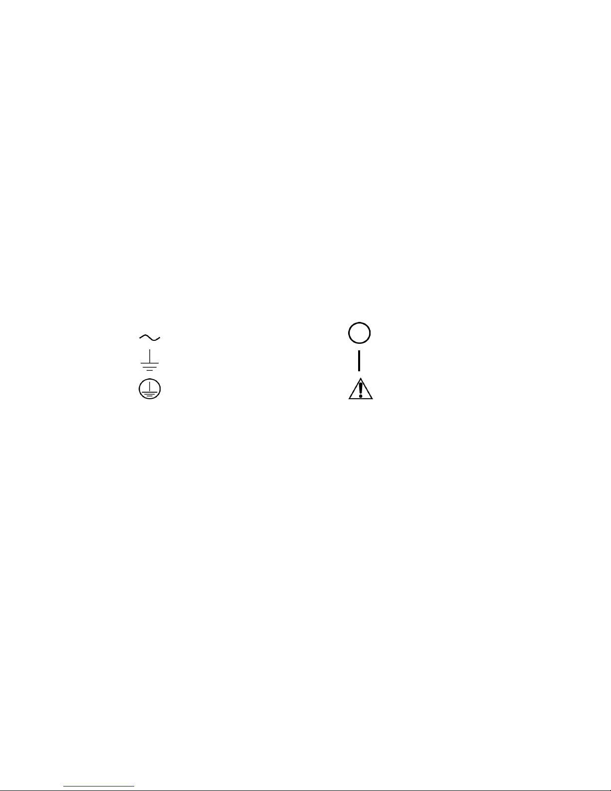
Power Supply Safety Markings
Alternating Current Off (Supply)
Earth (Ground) Terminal On (Supply)
Caution (Check manual for
Protective Conductor Terminal
additional information.)
viii Operating Manual for Multichannel Functionality (GPIB-M)
Page 11

Table of Contents
About This Manual . . . . . . . . . . . . . . . . . . . . . . . . . . . . . . . . . . . . . . . . . . . . . . . . . . . vii
List of Tables . . . . . . . . . . . . . . . . . . . . . . . . . . . . . . . . . . . . . . . . . . . . . . . . . . . . . . .xiii
List of Figures . . . . . . . . . . . . . . . . . . . . . . . . . . . . . . . . . . . . . . . . . . . . . . . . . . . . . . . xv
Section 1. Features and Specifications
Description . . . . . . . . . . . . . . . . . . . . . . . . . . . . . . . . . . . . . . . . . . . . . . . . . . . . . . . . . 17
Features and Functions . . . . . . . . . . . . . . . . . . . . . . . . . . . . . . . . . . . . . . . . . . . . . . . 17
Features. . . . . . . . . . . . . . . . . . . . . . . . . . . . . . . . . . . . . . . . . . . . . . . . . . . . . . . 17
Programmable Functions. . . . . . . . . . . . . . . . . . . . . . . . . . . . . . . . . . . . . . . . . . 18
Readback Functions . . . . . . . . . . . . . . . . . . . . . . . . . . . . . . . . . . . . . . . . . . . . . 18
Specifications . . . . . . . . . . . . . . . . . . . . . . . . . . . . . . . . . . . . . . . . . . . . . . . . . . . . . . . 19
Section 2. Installation and Configuration
Introduction. . . . . . . . . . . . . . . . . . . . . . . . . . . . . . . . . . . . . . . . . . . . . . . . . . . . . . . . . 25
Initial Inspection . . . . . . . . . . . . . . . . . . . . . . . . . . . . . . . . . . . . . . . . . . . . . . . . . . . . . 25
Basic Setup Procedure . . . . . . . . . . . . . . . . . . . . . . . . . . . . . . . . . . . . . . . . . . . . . . . . 31
Setup Procedure . . . . . . . . . . . . . . . . . . . . . . . . . . . . . . . . . . . . . . . . . . . . . . . . 32
Power On Service Request . . . . . . . . . . . . . . . . . . . . . . . . . . . . . . . . . . . . . . . . 33
Configure for GPIB Operation. . . . . . . . . . . . . . . . . . . . . . . . . . . . . . . . . . . . . . . . . . . 34
Change Remote Control Source . . . . . . . . . . . . . . . . . . . . . . . . . . . . . . . . . . . . 34
Set GPIB Address . . . . . . . . . . . . . . . . . . . . . . . . . . . . . . . . . . . . . . . . . . . . . . . 34
Configure for Multichannel Operation. . . . . . . . . . . . . . . . . . . . . . . . . . . . . . . . . . . . . 35
Multichannel Connections . . . . . . . . . . . . . . . . . . . . . . . . . . . . . . . . . . . . . . . . . 35
Multichannel Configuration. . . . . . . . . . . . . . . . . . . . . . . . . . . . . . . . . . . . . . . . . 35
CANbus . . . . . . . . . . . . . . . . . . . . . . . . . . . . . . . . . . . . . . . . . . . . . . . . . . . . . . . 36
CANbus Cables . . . . . . . . . . . . . . . . . . . . . . . . . . . . . . . . . . . . . . . . . . . . . . . . . 36
Configuration of CAN-only Interface Cards . . . . . . . . . . . . . . . . . . . . . . . . . . . . 36
Setup . . . . . . . . . . . . . . . . . . . . . . . . . . . . . . . . . . . . . . . . . . . . . . . . . . . . . . . . . 37
Using Multichannel Operation . . . . . . . . . . . . . . . . . . . . . . . . . . . . . . . . . . . . . . 37
Multichannel Commands . . . . . . . . . . . . . . . . . . . . . . . . . . . . . . . . . . . . . . . . . . 38
Broadcasting Commands. . . . . . . . . . . . . . . . . . . . . . . . . . . . . . . . . . . . . . . . . . 39
Specifications. . . . . . . . . . . . . . . . . . . . . . . . . . . . . . . . . . . . . . . . . . . . . . . . . . . 39
User Lines. . . . . . . . . . . . . . . . . . . . . . . . . . . . . . . . . . . . . . . . . . . . . . . . . . . . . . . . . . 40
User Lines Connection (XT, HPD, XPD) . . . . . . . . . . . . . . . . . . . . . . . . . . . . . . 41
Section 3. Operation
Overview. . . . . . . . . . . . . . . . . . . . . . . . . . . . . . . . . . . . . . . . . . . . . . . . . . . . . . . . . . . 43
Powering ON the Power Supply. . . . . . . . . . . . . . . . . . . . . . . . . . . . . . . . . . . . . 43
Power Supply Operating States . . . . . . . . . . . . . . . . . . . . . . . . . . . . . . . . . . . . . . . . . 44
Power-On. . . . . . . . . . . . . . . . . . . . . . . . . . . . . . . . . . . . . . . . . . . . . . . . . . . . . .44
Output Shutdown . . . . . . . . . . . . . . . . . . . . . . . . . . . . . . . . . . . . . . . . . . . . . . . . 44
Soft Start . . . . . . . . . . . . . . . . . . . . . . . . . . . . . . . . . . . . . . . . . . . . . . . . . . . . . . 44
Normal Operation. . . . . . . . . . . . . . . . . . . . . . . . . . . . . . . . . . . . . . . . . . . . . . . . 44
Calibration . . . . . . . . . . . . . . . . . . . . . . . . . . . . . . . . . . . . . . . . . . . . . . . . . . . . . 44
Release 2.1 ix
Page 12

Power Supply Regulation Modes. . . . . . . . . . . . . . . . . . . . . . . . . . . . . . . . . . . . . . . . 45
Constant Voltage (CV) . . . . . . . . . . . . . . . . . . . . . . . . . . . . . . . . . . . . . . . . . . . 45
Constant Current (CC) . . . . . . . . . . . . . . . . . . . . . . . . . . . . . . . . . . . . . . . . . . . 45
Automatic Mode Crossover. . . . . . . . . . . . . . . . . . . . . . . . . . . . . . . . . . . . . . . . 45
Remote Control Modes . . . . . . . . . . . . . . . . . . . . . . . . . . . . . . . . . . . . . . . . . . . . . . . 46
Front Panel LEDs. . . . . . . . . . . . . . . . . . . . . . . . . . . . . . . . . . . . . . . . . . . . . . . . . . . . 47
Power Supply Operation . . . . . . . . . . . . . . . . . . . . . . . . . . . . . . . . . . . . . . . . . . . . . . 48
Change Remote/Local Mode. . . . . . . . . . . . . . . . . . . . . . . . . . . . . . . . . . . . . . . 48
Power On Remote State . . . . . . . . . . . . . . . . . . . . . . . . . . . . . . . . . . . . . . . . . . 49
Enable Output . . . . . . . . . . . . . . . . . . . . . . . . . . . . . . . . . . . . . . . . . . . . . . . . . . 49
Set Voltage and Current . . . . . . . . . . . . . . . . . . . . . . . . . . . . . . . . . . . . . . . . . . 49
Readback . . . . . . . . . . . . . . . . . . . . . . . . . . . . . . . . . . . . . . . . . . . . . . . . . . . . . 50
Configure Output Protection . . . . . . . . . . . . . . . . . . . . . . . . . . . . . . . . . . . . . . . 51
OVP. . . . . . . . . . . . . . . . . . . . . . . . . . . . . . . . . . . . . . . . . . . . . . . . . . . . . . . . . . 52
Fold Protection . . . . . . . . . . . . . . . . . . . . . . . . . . . . . . . . . . . . . . . . . . . . . . . . . 52
Additional Protections . . . . . . . . . . . . . . . . . . . . . . . . . . . . . . . . . . . . . . . . . . . . 53
Set Shutdown Recovery for AC Off. . . . . . . . . . . . . . . . . . . . . . . . . . . . . . . . . . 53
AC Off Protection . . . . . . . . . . . . . . . . . . . . . . . . . . . . . . . . . . . . . . . . . . . . . . . 53
Over Temperature Protection . . . . . . . . . . . . . . . . . . . . . . . . . . . . . . . . . . . . . . 53
Clear Protection Event . . . . . . . . . . . . . . . . . . . . . . . . . . . . . . . . . . . . . . . . . . . 54
Shutdown vs Protection Alarm . . . . . . . . . . . . . . . . . . . . . . . . . . . . . . . . . . . . . 54
User Settings (Save and Recall) . . . . . . . . . . . . . . . . . . . . . . . . . . . . . . . . . . . . 55
Set Up Power ON Defaults . . . . . . . . . . . . . . . . . . . . . . . . . . . . . . . . . . . . . . . . 56
Power On Output State . . . . . . . . . . . . . . . . . . . . . . . . . . . . . . . . . . . . . . . . . . . 57
Reset. . . . . . . . . . . . . . . . . . . . . . . . . . . . . . . . . . . . . . . . . . . . . . . . . . . . . . . . . 57
Read Error Messages . . . . . . . . . . . . . . . . . . . . . . . . . . . . . . . . . . . . . . . . . . . . 58
Clear Status. . . . . . . . . . . . . . . . . . . . . . . . . . . . . . . . . . . . . . . . . . . . . . . . . . . . 58
Configure Auxiliary Status Lines . . . . . . . . . . . . . . . . . . . . . . . . . . . . . . . . . . . . 58
Auto Sequencing . . . . . . . . . . . . . . . . . . . . . . . . . . . . . . . . . . . . . . . . . . . . . . . . . . . . 60
Programming a Sequence. . . . . . . . . . . . . . . . . . . . . . . . . . . . . . . . . . . . . . . . . 60
Deleting a Sequence. . . . . . . . . . . . . . . . . . . . . . . . . . . . . . . . . . . . . . . . . . . . . 63
Using Auto Sequencing. . . . . . . . . . . . . . . . . . . . . . . . . . . . . . . . . . . . . . . . . . . 63
Set V, I, and P Limits. . . . . . . . . . . . . . . . . . . . . . . . . . . . . . . . . . . . . . . . . . . . . 65
Triggered Setpoints . . . . . . . . . . . . . . . . . . . . . . . . . . . . . . . . . . . . . . . . . . . . . . 65
Triggering Commands. . . . . . . . . . . . . . . . . . . . . . . . . . . . . . . . . . . . . . . . . . . . 66
Slew Rate . . . . . . . . . . . . . . . . . . . . . . . . . . . . . . . . . . . . . . . . . . . . . . . . . . . . . 67
Identification Query . . . . . . . . . . . . . . . . . . . . . . . . . . . . . . . . . . . . . . . . . . . . . . 68
Option Identification Query . . . . . . . . . . . . . . . . . . . . . . . . . . . . . . . . . . . . . . . . 68
SCPI Version Query . . . . . . . . . . . . . . . . . . . . . . . . . . . . . . . . . . . . . . . . . . . . . 68
Section 4. Status Registers
Overview . . . . . . . . . . . . . . . . . . . . . . . . . . . . . . . . . . . . . . . . . . . . . . . . . . . . . . . . . . 69
Condition Register. . . . . . . . . . . . . . . . . . . . . . . . . . . . . . . . . . . . . . . . . . . . . . . 69
Event Register. . . . . . . . . . . . . . . . . . . . . . . . . . . . . . . . . . . . . . . . . . . . . . . . . . 69
Enable Register. . . . . . . . . . . . . . . . . . . . . . . . . . . . . . . . . . . . . . . . . . . . . . . . . 69
Transition Filters . . . . . . . . . . . . . . . . . . . . . . . . . . . . . . . . . . . . . . . . . . . . . . . . 69
OPERation Status Register. . . . . . . . . . . . . . . . . . . . . . . . . . . . . . . . . . . . . . . . 69
REGulating Sub-Register . . . . . . . . . . . . . . . . . . . . . . . . . . . . . . . . . . . . . . . . . 72
x Operating Manual for Multichannel Functionality (GPIB-M)
Page 13

SHUTdown Sub-Register. . . . . . . . . . . . . . . . . . . . . . . . . . . . . . . . . . . . . . . . . .73
Protection SHUTdown Sub-Register . . . . . . . . . . . . . . . . . . . . . . . . . . . . . . . . . 73
Remote CONtrol Sub-Register. . . . . . . . . . . . . . . . . . . . . . . . . . . . . . . . . . . . . . 73
Current SHare Sub-Register . . . . . . . . . . . . . . . . . . . . . . . . . . . . . . . . . . . . . . . 74
QUEStionable Status Register. . . . . . . . . . . . . . . . . . . . . . . . . . . . . . . . . . . . . . 74
VOLTage Sub-Register . . . . . . . . . . . . . . . . . . . . . . . . . . . . . . . . . . . . . . . . . . . 76
CURRent Sub-Register . . . . . . . . . . . . . . . . . . . . . . . . . . . . . . . . . . . . . . . . . . . 77
Standard Event Status Register. . . . . . . . . . . . . . . . . . . . . . . . . . . . . . . . . . . . . 77
Status Byte. . . . . . . . . . . . . . . . . . . . . . . . . . . . . . . . . . . . . . . . . . . . . . . . . . . . . 79
Master Summary Status (MSS) . . . . . . . . . . . . . . . . . . . . . . . . . . . . . . . . . . . . . 80
Request Service (RQS) . . . . . . . . . . . . . . . . . . . . . . . . . . . . . . . . . . . . . . . . . . . 80
Status Register Commands . . . . . . . . . . . . . . . . . . . . . . . . . . . . . . . . . . . . . . . . . . . . 81
SCPI Status Commands . . . . . . . . . . . . . . . . . . . . . . . . . . . . . . . . . . . . . . . . . . 81
IEEE 488.2 Status and Event Commands . . . . . . . . . . . . . . . . . . . . . . . . . . . . . 82
Operation Status Register Commands . . . . . . . . . . . . . . . . . . . . . . . . . . . . . . . 85
Regulating Sub-Register Commands. . . . . . . . . . . . . . . . . . . . . . . . . . . . . . . . . 85
Shutdown Sub-Register Commands . . . . . . . . . . . . . . . . . . . . . . . . . . . . . . . . . 85
Protection Shutdown Sub-Register Commands. . . . . . . . . . . . . . . . . . . . . . . . . 86
Remote Control Sub-Register Commands. . . . . . . . . . . . . . . . . . . . . . . . . . . . . 86
Current Share Sub-Register Commands . . . . . . . . . . . . . . . . . . . . . . . . . . . . . . 87
Questionable Status Register Commands. . . . . . . . . . . . . . . . . . . . . . . . . . . . . 87
Voltage Sub-Register Commands . . . . . . . . . . . . . . . . . . . . . . . . . . . . . . . . . . . 88
Current Sub-Register Commands . . . . . . . . . . . . . . . . . . . . . . . . . . . . . . . . . . . 88
Section 5. Current Sharing
Overview. . . . . . . . . . . . . . . . . . . . . . . . . . . . . . . . . . . . . . . . . . . . . . . . . . . . . . . . . . . 89
Theory of Operation . . . . . . . . . . . . . . . . . . . . . . . . . . . . . . . . . . . . . . . . . . . . . . 90
Configure Current Share . . . . . . . . . . . . . . . . . . . . . . . . . . . . . . . . . . . . . . . . . . 90
Setup Current Sharing Network . . . . . . . . . . . . . . . . . . . . . . . . . . . . . . . . . . . . . 90
Operation . . . . . . . . . . . . . . . . . . . . . . . . . . . . . . . . . . . . . . . . . . . . . . . . . . . . . . . . . . 91
Errors . . . . . . . . . . . . . . . . . . . . . . . . . . . . . . . . . . . . . . . . . . . . . . . . . . . . . . . . . 91
Appendix A. GPIB
Overview. . . . . . . . . . . . . . . . . . . . . . . . . . . . . . . . . . . . . . . . . . . . . . . . . . . . . . . . . . . 93
Codes and Standards. . . . . . . . . . . . . . . . . . . . . . . . . . . . . . . . . . . . . . . . . . . . . . . . . 93
Message Terminators. . . . . . . . . . . . . . . . . . . . . . . . . . . . . . . . . . . . . . . . . . . . . . . . . 93
Address Range . . . . . . . . . . . . . . . . . . . . . . . . . . . . . . . . . . . . . . . . . . . . . . . . . . . . . . 93
Primary. . . . . . . . . . . . . . . . . . . . . . . . . . . . . . . . . . . . . . . . . . . . . . . . . . . . . . . .93
Secondary . . . . . . . . . . . . . . . . . . . . . . . . . . . . . . . . . . . . . . . . . . . . . . . . . . . . . 93
Service Request and Polling. . . . . . . . . . . . . . . . . . . . . . . . . . . . . . . . . . . . . . . . . . . . 93
Protocol Specifications . . . . . . . . . . . . . . . . . . . . . . . . . . . . . . . . . . . . . . . . . . . . . . . . 94
Multiline Control Functions. . . . . . . . . . . . . . . . . . . . . . . . . . . . . . . . . . . . . . . . . 94
Interface Functions. . . . . . . . . . . . . . . . . . . . . . . . . . . . . . . . . . . . . . . . . . . . . . . 94
Electrical Specifications . . . . . . . . . . . . . . . . . . . . . . . . . . . . . . . . . . . . . . . . . . . . . . . 95
Driver Requirements . . . . . . . . . . . . . . . . . . . . . . . . . . . . . . . . . . . . . . . . . . . . . 95
Mechanical Specifications . . . . . . . . . . . . . . . . . . . . . . . . . . . . . . . . . . . . . . . . . . . . . 95
Performance Specifications . . . . . . . . . . . . . . . . . . . . . . . . . . . . . . . . . . . . . . . . . . . . 95
Release 2.1 xi
Page 14

Appendix B. SCPI Command Reference
Overview . . . . . . . . . . . . . . . . . . . . . . . . . . . . . . . . . . . . . . . . . . . . . . . . . . . . . . . . . . 97
Codes and Standards . . . . . . . . . . . . . . . . . . . . . . . . . . . . . . . . . . . . . . . . . . . . . . . . 97
IEEE 488.2 Requirements. . . . . . . . . . . . . . . . . . . . . . . . . . . . . . . . . . . . . . . . . 97
SCPI Requirements. . . . . . . . . . . . . . . . . . . . . . . . . . . . . . . . . . . . . . . . . . . . . . 97
IEEE-488.2/SCPI Syntax and Style . . . . . . . . . . . . . . . . . . . . . . . . . . . . . . . . . . . . . . 98
Parameters . . . . . . . . . . . . . . . . . . . . . . . . . . . . . . . . . . . . . . . . . . . . . . . . . . . . 98
Understanding SCPI Commands. . . . . . . . . . . . . . . . . . . . . . . . . . . . . . . . . . . . . . . . 99
SCPI Command Hierarchy . . . . . . . . . . . . . . . . . . . . . . . . . . . . . . . . . . . . . . . . 99
Using SCPI Commands . . . . . . . . . . . . . . . . . . . . . . . . . . . . . . . . . . . . . . . . . . 99
Parameter Types. . . . . . . . . . . . . . . . . . . . . . . . . . . . . . . . . . . . . . . . . . . . . . . 102
SCPI Command Summary. . . . . . . . . . . . . . . . . . . . . . . . . . . . . . . . . . . . . . . . . . . . 103
Notations Used in the Tables . . . . . . . . . . . . . . . . . . . . . . . . . . . . . . . . . . . . . 103
Expressions . . . . . . . . . . . . . . . . . . . . . . . . . . . . . . . . . . . . . . . . . . . . . . . . . . . . . . . 115
Appendix C. Error Messages
Overview . . . . . . . . . . . . . . . . . . . . . . . . . . . . . . . . . . . . . . . . . . . . . . . . . . . . . . . . . 117
Command Error List. . . . . . . . . . . . . . . . . . . . . . . . . . . . . . . . . . . . . . . . . . . . . . . . . 118
Execution Error List . . . . . . . . . . . . . . . . . . . . . . . . . . . . . . . . . . . . . . . . . . . . . . . . . 118
Device-Specific Error List. . . . . . . . . . . . . . . . . . . . . . . . . . . . . . . . . . . . . . . . . . . . . 120
Query Error List . . . . . . . . . . . . . . . . . . . . . . . . . . . . . . . . . . . . . . . . . . . . . . . . . . . . 121
User Request Event. . . . . . . . . . . . . . . . . . . . . . . . . . . . . . . . . . . . . . . . . . . . . . . . . 121
Operation Complete Event. . . . . . . . . . . . . . . . . . . . . . . . . . . . . . . . . . . . . . . . . . . . 121
Front Panel Error Codes . . . . . . . . . . . . . . . . . . . . . . . . . . . . . . . . . . . . . . . . . . . . . 122
CPU Error Codes. . . . . . . . . . . . . . . . . . . . . . . . . . . . . . . . . . . . . . . . . . . . . . . . . . . 122
Analog Programming Interface Error codes. . . . . . . . . . . . . . . . . . . . . . . . . . . . . . . 122
Auto Sequencing Error Codes . . . . . . . . . . . . . . . . . . . . . . . . . . . . . . . . . . . . . . . . . 122
CANbus Error Codes . . . . . . . . . . . . . . . . . . . . . . . . . . . . . . . . . . . . . . . . . . . . . . . . 123
Multichannel Error Codes . . . . . . . . . . . . . . . . . . . . . . . . . . . . . . . . . . . . . . . . . . . . 123
Current Share Error Codes . . . . . . . . . . . . . . . . . . . . . . . . . . . . . . . . . . . . . . . . . . . 124
Appendix D. Calibration
Overview . . . . . . . . . . . . . . . . . . . . . . . . . . . . . . . . . . . . . . . . . . . . . . . . . . . . . . . . . 125
Entering Calibration Mode . . . . . . . . . . . . . . . . . . . . . . . . . . . . . . . . . . . . . . . . . . . . 125
Security code. . . . . . . . . . . . . . . . . . . . . . . . . . . . . . . . . . . . . . . . . . . . . . . . . . 126
Setup and Equipment . . . . . . . . . . . . . . . . . . . . . . . . . . . . . . . . . . . . . . . . . . . . . . . 126
Calibration Procedure . . . . . . . . . . . . . . . . . . . . . . . . . . . . . . . . . . . . . . . . . . . . . . . 127
Output Voltage . . . . . . . . . . . . . . . . . . . . . . . . . . . . . . . . . . . . . . . . . . . . . . . . 127
Output Current. . . . . . . . . . . . . . . . . . . . . . . . . . . . . . . . . . . . . . . . . . . . . . . . . 128
Exit calibration mode . . . . . . . . . . . . . . . . . . . . . . . . . . . . . . . . . . . . . . . . . . . . . . . . 129
Restore Factory Calibration . . . . . . . . . . . . . . . . . . . . . . . . . . . . . . . . . . . . . . . . . . . 129
xii Operating Manual for Multichannel Functionality (GPIB-M)
Page 15

List of Tables
Table 1.1 Specifications for HPD 300 W with GPIB-M or CANbus . . . . . . . . . . . 19
Table 1.2 Specifications for XFR 1200 W with GPIB-M or CANbus . . . . . . . . . . 20
Table 1.3 Specifications for XFR 2800 W with GPIB-M or CANbus . . . . . . . . . . 21
Table 1.4 Specifications for XHR 1000 W with GPIB-M or CANbus . . . . . . . . . . 22
Table 1.5 Specifications for XPD 500 W with GPIB-M or CANbus . . . . . . . . . . . 23
Table 1.6 Specifications for XT 60 W with GPIB-M or CANbus . . . . . . . . . . . . . 23
Table 2.1 Remote Mode Power On Conditions . . . . . . . . . . . . . . . . . . . . . . . . . . 33
Table 2.2 CANbus Pins . . . . . . . . . . . . . . . . . . . . . . . . . . . . . . . . . . . . . . . . . . . . 36
Table 2.3 User Line Pins . . . . . . . . . . . . . . . . . . . . . . . . . . . . . . . . . . . . . . . . . . . 40
Table 3.1 Power Supply Factory Defaults . . . . . . . . . . . . . . . . . . . . . . . . . . . . . . 46
Table 3.2 Features Affected by Reset (*RST) Command . . . . . . . . . . . . . . . . . . 57
Table 4.1 OPERation Status Register . . . . . . . . . . . . . . . . . . . . . . . . . . . . . . . . . 72
Table 4.2 REGulating Sub-Register . . . . . . . . . . . . . . . . . . . . . . . . . . . . . . . . . . 72
Table 4.3 SHUTdown Sub-Register . . . . . . . . . . . . . . . . . . . . . . . . . . . . . . . . . . 73
Table 4.4 Protection SHUTdown Sub-Register . . . . . . . . . . . . . . . . . . . . . . . . . . 73
Table 4.5 Remote CONtrol Sub-Register . . . . . . . . . . . . . . . . . . . . . . . . . . . . . . 74
Table 4.6 Current SHare Sub-Register . . . . . . . . . . . . . . . . . . . . . . . . . . . . . . . . 74
Table 4.7 QUEStionable Status Register . . . . . . . . . . . . . . . . . . . . . . . . . . . . . . 76
Table 4.8 VOLTage Sub-Register . . . . . . . . . . . . . . . . . . . . . . . . . . . . . . . . . . . . 76
Table 4.9 CURRent Sub-Register . . . . . . . . . . . . . . . . . . . . . . . . . . . . . . . . . . . . 77
Table 4.10 Standard Event Status Register . . . . . . . . . . . . . . . . . . . . . . . . . . . . . 78
Table 4.11 Status Byte Summary Register . . . . . . . . . . . . . . . . . . . . . . . . . . . . . . 79
Table 4.12 Preset Values of User Configurable Registers . . . . . . . . . . . . . . . . . . 81
Table A.1 Multiline Control Functions . . . . . . . . . . . . . . . . . . . . . . . . . . . . . . . . . 94
Table A.2 Interface Functions . . . . . . . . . . . . . . . . . . . . . . . . . . . . . . . . . . . . . . . 94
Table A.3 Driver Types for Interface Lines. . . . . . . . . . . . . . . . . . . . . . . . . . . . . . 95
Table B.1 IEEE 488.2 Commands . . . . . . . . . . . . . . . . . . . . . . . . . . . . . . . . . . . 104
Table B.2 Readback Commands . . . . . . . . . . . . . . . . . . . . . . . . . . . . . . . . . . . . 105
Table B.3 Commands for Output Control. . . . . . . . . . . . . . . . . . . . . . . . . . . . . . 106
Table B.4 Commands for Current Share . . . . . . . . . . . . . . . . . . . . . . . . . . . . . . 107
Table B.5 Commands for Calibration. . . . . . . . . . . . . . . . . . . . . . . . . . . . . . . . . 107
Table B.6 Command to Clear all Protection Mechanisms . . . . . . . . . . . . . . . . . 107
Table B.7 Commands for Fold Protection . . . . . . . . . . . . . . . . . . . . . . . . . . . . . 108
Table B.8 Commands for Triggering . . . . . . . . . . . . . . . . . . . . . . . . . . . . . . . . . 108
Table B.9 System Commands . . . . . . . . . . . . . . . . . . . . . . . . . . . . . . . . . . . . . .108
Table B.10 Status Commands . . . . . . . . . . . . . . . . . . . . . . . . . . . . . . . . . . . . . . . 109
Release 2.1 xiii
Page 16

List of Tables
Table B.11 Protection Commands . . . . . . . . . . . . . . . . . . . . . . . . . . . . . . . . . . . 112
Table B.12 User Lines. . . . . . . . . . . . . . . . . . . . . . . . . . . . . . . . . . . . . . . . . . . . . 112
Table B.13 Output State . . . . . . . . . . . . . . . . . . . . . . . . . . . . . . . . . . . . . . . . . . . 112
Table B.14 Auto Sequence Commands . . . . . . . . . . . . . . . . . . . . . . . . . . . . . . . 113
Table B.15 Expressions . . . . . . . . . . . . . . . . . . . . . . . . . . . . . . . . . . . . . . . . . . . 115
Table C.1 Command Error List . . . . . . . . . . . . . . . . . . . . . . . . . . . . . . . . . . . . . 118
Table C.2 Execution Error List. . . . . . . . . . . . . . . . . . . . . . . . . . . . . . . . . . . . . . 118
Table C.3 Device-Specific Error List . . . . . . . . . . . . . . . . . . . . . . . . . . . . . . . . . 120
Table C.4 Query Error List. . . . . . . . . . . . . . . . . . . . . . . . . . . . . . . . . . . . . . . . . 121
Table C.5 User Request Event . . . . . . . . . . . . . . . . . . . . . . . . . . . . . . . . . . . . . 121
Table C.6 Operation Complete Event . . . . . . . . . . . . . . . . . . . . . . . . . . . . . . . . 121
Table C.7 Front Panel Error Codes. . . . . . . . . . . . . . . . . . . . . . . . . . . . . . . . . . 122
Table C.8 CPU Error Codes . . . . . . . . . . . . . . . . . . . . . . . . . . . . . . . . . . . . . . . 122
Table C.9 Analog Programming Interface Error code . . . . . . . . . . . . . . . . . . . . 122
Table C.10 Auto Sequencing Error Codes . . . . . . . . . . . . . . . . . . . . . . . . . . . . . 122
Table C.11 CANbus Error Codes . . . . . . . . . . . . . . . . . . . . . . . . . . . . . . . . . . . . 123
Table C.12 Multichannel Error Codes . . . . . . . . . . . . . . . . . . . . . . . . . . . . . . . . . 123
Table C.13 Current Share Error Codes. . . . . . . . . . . . . . . . . . . . . . . . . . . . . . . . 124
xiv
Operating Manual for Multichannel Functionality (GPIB-M)
Page 17

List of Figures
Figure 2.1 XFR and XHR Power Supply Front Panel with GPIB-M Interface . . . . 26
Figure 2.2 XPD Power Supply Front Panel with GPIB Interface. . . . . . . . . . . . . . 27
Figure 2.3 XT and HPD Power Supply Front Panel with GPIB Interface . . . . . . . 27
Figure 2.4 XFR 2800 Watt Power Supply Rear Panel with GPIB-M Interface . . . 28
Figure 2.5 XFR 1200 Watt Power Supply Rear Panel with GPIB-M Interface . . . 28
Figure 2.6 XHR Power Supply Rear Panel with GPIB-M Interface. . . . . . . . . . . . 29
Figure 2.7 XPD Power Supply Rear Panel with GPIB-M Interface . . . . . . . . . . . . 29
Figure 2.8 XT/HPD Power Supply Rear Panel with GPIB-M Interface . . . . . . . . . 30
Figure 2.9 XFR GPIB Cable with Ferrite Block. . . . . . . . . . . . . . . . . . . . . . . . . . . 31
Figure 2.10 Connections for Multichannel Operation . . . . . . . . . . . . . . . . . . . . . . . 37
Figure 2.11 User Signals Connector (XT, HPD and XPD) . . . . . . . . . . . . . . . . . . . 41
Figure 2.12 XT, HPD, XPD User Cable with Ferrite Block . . . . . . . . . . . . . . . . . . . 41
Figure 2.13 Schematic For User Line Interface . . . . . . . . . . . . . . . . . . . . . . . . . . . 42
Figure 4.1 Operation Status Registers . . . . . . . . . . . . . . . . . . . . . . . . . . . . . . . . . 71
Figure 4.2 Questionable Status Registers . . . . . . . . . . . . . . . . . . . . . . . . . . . . . . 75
Figure 4.3 IEEE 488.2 Status Register and Status Byte. . . . . . . . . . . . . . . . . . . . 77
Figure 5.1 Example of Current Share Operation . . . . . . . . . . . . . . . . . . . . . . . . . 89
Release 2.1 xv
Page 18

List of Figures
xvi
Operating Manual for Multichannel Functionality (GPIB-M)
Page 19

Section 1. Features and Specifications
Description
The internal GPIB-M interface card allows you to operate your power supply from
a computer controller via the IEEE-488 communications bus.
The GPIB-M interface allows complete remote programming of your power supply,
including status reporting, settings query, and service request generation with
user-designated conditions. Both the voltage and current output are precisely
programmed directly in volts and amps with 16-bit resolution. Additionally, the
16-bit readbacks measure the actual power supply output. The programming
command set is easy to use and includes software calibration commands. The
interface card comes with several protection features such as programmable over
and under voltage protection, and soft limits.
Multichannel addressing via CANbus allows up to 50 power supplies to be
controlled from one GPIB address. This manual covers operation of both the
GPIB-M and CAN-only interface cards.
Features and Functions
Features • 16-bit programming and readback of voltage and current
• Programmable soft limits for voltage and current
• LED status signals: remote operation, service request and shutdown; (XFR and
XHR only) error, addressed, over voltage protection, auxiliary status bits
• Software calibration
• Automatic voltage/current mode crossover
• Shutdown or warning for over- and under-programmed trip points
• Programmable auxiliary status lines for monitoring power supply conditions
• Remote interlock and trigger lines
• Selectable standby, programmed sequence and other power-on defaults
• Active current sharing with parallel connected units for higher power
requirements
• CANbus communications link for multichannel addressing, and master/slave
current sharing
• Extensive SCPI command set for control and status monitoring
Release 2.1 17
Page 20

Features and Specifications
Features and Functions
Programmable
Functions
Readback
Functions
• Output voltage and current
• Soft limits for voltage and current
• Overvoltage protection
• Output enable/disable
• Ten, 99-step auto sequences for easy programming of complex test routines
• Ten stored settings
• Five load protection mechanisms including fold protection in CV or CC mode
• Actual measured voltage and current
• Voltage and current settings
• Soft voltage and current limits
• Overvoltage protection setting
• Programming error codes
• Power supply model and version identification
• Firmware revision levels
18 Operating Manual for Multichannel Functionality (GPIB-M)
Page 21

Specifications
Features and Specifications
Specifications
The specifications in this section are warranted at 25°C ±5°C unless otherwise
specified. All specifications are subject to change without notice.
Table 1.1 Specifications for HPD 300 W with GPIB-M or CANbus
Models 15-20 30-10 60-5
Program Resolution
Voltage
Current
Program Accuracy
1
Voltage
Current
Readback Resolution
Voltage
Current
Readback Accuracy
Voltage
Current
1
2.4mV
2.8mA
60mV
±0.1%
75mA
±0.12%
2.4mV
2.8mA
45mV
±0.3%
75mA
±0.12%
4.7mV
1.4mA
70mV
±0.1%
50mA
±0.12%
4.7mV
1.4mA
90mV
±0.3%
40mA
±0.12%
9.3mV
0.7mA
90mV
±0.12%
25mA
±0.1%
9.3mV
0.7mA
175mV
±0.3%
25mA
±0.1%
1. Apply accuracy specifications according to the following voltage program accuracy example:
Set a model HPD 15-20 power supply to 10 volts.
The expected result will be within the range of 10 volts ± 60mV ± 0.1% of the set voltage of
10 volts.
Release 2.1 19
Page 22

Features and Specifications
Specifications
Table 1. 2 Specifications for XFR 1200 W with GPIB-M or CANbus
Models 7.5-140 12-100 20-60 35-35 40-30
Program Resolution
Voltage
Current
Program Accuracy
Voltage
Current
1
1.16mV
19.6mA
10mV
±0.12%
500mA
±0.1%
1.8mV
14mA
50mV
±0.12%
460mA
±0.1%
3.08mV
8.4mA
75mV
±0.12%
250mA
±0.1%
5.4mV
5.4mA
75mV
±0.3%
200mA
±0.1%
6.2mV
4.2mA
75mV
±0.3%
150mA
±0.15%
Readback Resolution
Voltage
Current
Readback Accuracy
Voltage
Current
1
1.16mV
19.6mA
30mV
±0.12%
500mA
±0.1%
1.8mV
14mA
60mV
±0.12%
460mA
±0.1%
3.08mV
8.4mA
75mV
±0.12%
250mA
±0.1%
5.4mV
5.4mA
75mV
±0.3%
200mA
±0.1%
6.2mV
4.2mA
75mV
±0.3%
150mA
±0.15%
Models 60-20 100-12 150-8 300-4 600-2
Program Resolution
Voltage
Current
Program Accuracy
Voltage
Current
1
9.2mV
2.8mA
150mV
±0.25%
120mA
±0.1%
15.4mV
1.68mA
150mV
±0.35%
80mA
±0.1%
23.1mV
1.12mA
225mV
±0.35%
80mA
±0.1%
46.2mV
0.56mA
225mV
±0.35%
80mA
±0.1%
92.4mV
0.28mA
250mV
±0.35%
50mA
±0.1%
Readback Resolution
Voltage
Current
Readback Accuracy
Voltage
Current
1. Apply accuracy specifications according to the following voltage program accuracy example:
Set a model XFR 20-60 power supply to 10 volts.
The expected result will be within the range of 10 volts ± 75mV ± 0.12% of the set voltage of 10 volts.
1
9.2mV
2.8mA
150mV
±0.25%
120mA
±0.1%
15.4mV
1.68mA
150mV
±0.35%
80mA
±0.1%
23.1mV
1.12mA
225mV
±0.35%
80mA
±0.1%
46.2mV
0.56mA
225mV
±0.35%
80mA
±0.1%
92.4mV
0.28mA
250mV
±0.35%
50mA
±0.1%
20 Operating Manual for Multichannel Functionality (GPIB-M)
Page 23

Features and Specifications
Specifications
Table 1.3 Specifications for XFR 2800 W with GPIB-M or CANbus
Models 7.5-300 12-220 20-130 33-85 40-70
Program Resolution
Voltage
Current
Program Accuracy
Voltage
Current
1
1.16mV
42.0mA
10mV
±0.12%
900mA
±0.1%
1.8mV
30.8mA
50mV
±0.12%
750mA
±0.1%
3.08mV
18.2mA
75mV
±0.12%
500mA
±0.1%
5.1mV
13.0mA
75mV
±0.3%
425mA
±0.1%
6.2mV
9.8mA
75mV
±0.3%
350mA
±0.15%
Readback Resolution
Voltage
Current
1.16mV
42.0mA
1.8mV
30.8mA
3.08mV
18.2mA
5.1mV
13.0mA
6.2mV
9.8mA
Readback Accuracy
Voltage
Current
30mV
±0.12%
900mA
±0.1%
60mV
±0.12%
750mA
±0.1%
75mV
±0.12%
500mA
±0.1%
75mV
±0.3%
425mA
±0.1%
75mV
±0.3%
350mA
±0.1%
Models 60-46 100-28 150-18 300-9 600-4
Program Resolution
Voltage
Current
Program Accuracy
Voltage
Current
1
9.2mV
6.44mA
150mV
±0.25%
250mA
±0.1%
15.4mV
3.92mA
150mV
±0.35%
140mA
±0.1%
23.1mV
2.52mA
225mV
±0.35%
120mA
±0.1%
46.2mV
1.26mA
225mV
±0.35%
80mA
±0.1%
92.4mV
0.56mA
250mV
±0.35%
80mA
±0.1%
Readback Resolution
Voltage
Current
Readback Accuracy
Voltage
Current
1. Apply accuracy specifications according to the following voltage program accuracy example:
Set a model XFR 20-130 power supply to 10 volts.
The expected result will be within the range of 10 volts ± 75mV ± 0.12% of the set voltage of 10 volts
1
9.2mV
6.44mA
150mV
±0.25%
250mA
±0.1%
15.4mV
3.92mA
150mV
±0.35%
140mA
±0.15%
23.1mV
2.52mA
225mV
±0.35%
120mA
±0.1%
46.2mV
1.26mA
225mV
±0.35%
80mA
±0.1%
92.4mV
0.56mA
250mV
±0.35%
80mA
±0.1%
Release 2.1 21
Page 24

Features and Specifications
Specifications
Table 1. 4 Specifications for XHR 1000 W with GPIB-M or CANbus
Models 7.5-130 20-50 33-33 40-25 60-18
Program Resolution
Voltage
Current
Program Accuracy
Voltage
Current
1
1.16mV
42.0mA
10mV
±0.12%
900mA
±0.1%
1.8mV
30.8mA
50mV
±0.12%
750mA
±0.1%
3.08mV
18.2mA
75mV
±0.12%
500mA
±0.1%
6.2mV
9.8mA
75mV
±0.3%
350mA
±0.1%
9.2mV
6.44mA
150mV
±0.25%
250mA
±0.1%
Readback Resolution
Voltage
Current
Readback Accuracy
Voltage
Current
1
1.16mV
42.0mA
30mV
±0.12%
900mA
±0.1%
1.8mV
30.8mA
60mV
±0.12%
750mA
±0.1%
3.08mV
18.2mA
75mV
±0.12%
500mA
±0.1%
6.2mV
9.8mA
75mV
±0.3%
350mA
±0.1%
9.2mV
6.44mA
150mV
±0.25%
250mA
±0.1%
Models 100-10 150-7 300-3.5 600-1.7
Program Resolution
Voltage
Current
Program Accuracy
Voltage
Current
1
15.4mV
3.92mA
150mV
±0.35%
140mA
±0.15%
23.1mV
2.52mA
225mV
±0.35%
120mA
±0.1%
46.2mV
1.26mA
225mV
±0.35%
80mA
±0.1%
92.4mV
0.56mA
250mV
±0.35%
80mA
±0.1%
Readback Resolution
Voltage
Current
Readback Accuracy
Voltage
Current
1. Apply accuracy specifications according to the following voltage program accuracy example:
Set a model XHR 20-50 power supply to 10 volts.
The expected result will be within the range of 10 volts ± 50mV ± 0.12% of the set voltage of 10 volts.
1
15.4mV
3.92mA
150mV
±0.35%
140mA
±0.15%
23.1mV
2.52mA
225mV
±0.35%
120mA
±0.1%
46.2mV
1.26mA
225mV
±0.35%
80mA
±0.1%
92.4mV
0.56mA
250mV
±0.35%
80mA
±0.1%
22 Operating Manual for Multichannel Functionality (GPIB-M)
Page 25

Features and Specifications
Specifications
Table 1.5 Specifications for XPD 500 W with GPIB-M or CANbus
Models 7.5-67 18-30 33-16 60-9 120-4.5
Program Resolution
Voltage
Current
Program Accuracy
Voltage
Current
1
1.2mV
5.2mA
10mV
±0.12%
250mA
±0.1%
4.6mV
3.6mA
75mV
±0.12%
140mA
±0.1%
5.1mV
2.9mA
75mV
±0.12%
115mA
±0.15%
9.3mV
1.3mA
150mV
±0.3%
80mA
±0.15%
18.6mV
0.7mA
180mV
±0.25%
80mA
±0.1%
Readback Resolution
Voltage
Current
Readback Accuracy
Voltage
Current
1
1.2mV
5.2mA
30mV
±0.12%
250mA
±0.1%
4.6mV
3.6mA
75mV
±0.12%
140mA
±0.1%
5.1mV
2.4mA
75mV
±0.2%
115mA
±0.15%
9.3mV
1.3mA
150mV
±0.3%
80mA
±0.15%
18.6mV
0.7mA
180mV
±0.25%
80mA
±0.1%
1. Apply accuracy specifications according to the following voltage program accuracy example:
Set a model XPD 18-30 power supply to 10 volts.
The expected result will be within the range of 10 volts ± 75mV ± 0.12% of the set voltage of 10 volts.
Table 1.6 Specifications for XT 60 W with GPIB-M or CANbus
Models 7-6 15-4 20-3 30-2 60-1 120-0.5 250-0.25
Program Resolution
Voltage
Current
Program Accuracy
Voltage
Current
1
1.1mV
1.0mA
10mV
±0.1%
110mA
±0.15%
2.4mV
0.6mA
20mV
±0.1%
70mA
±0.15%
3.1mV
0.5mA
20mV
±0.15%
50mA
±0.15%
4.7mV
0.3mA
30mV
±0.15%
40mA
±0.15%
9.3mV
0.2mA
200mV
±0.15%
26mA
±0.2%
17mV
0.1mA
400mV
±0.15%
13mA
±0.2%
17mV
0.1mA
400mV
±0.15%
13mA
±0.2%
Readback Resolution
Voltage
Current
Readback Accuracy
Voltage
Current
1
1.1mV
1.0mA
10mV
±0.15%
110mA
±0.15%
2.4mV
0.6mA
10mV
±0.1%
70mA
±0.15%
3.1mV
0.5mA
10mV
±0.1%
50mA
±0.15%
4.7mV
0.3mA
15mV
±0.1%
40mA
±0.15%
9.3mV
0.2mA
35mV
±0.15%
26mA
±0.2%
17mV
0.1mA
70mV
±0.15%
13mA
±0.2%
17mV
0.1mA
70mV
±0.15%
13mA
±0.2%
1. Apply accuracy specifications according to the following voltage program accuracy example:
Set a model XT 15-4 power supply to 10 volts.
The expected result will be within the range of 10 volts ± 20mV ± 0.1% of the set voltage of 10 volts.
Release 2.1 23
Page 26

Features and Specifications
Specifications
24 Operating Manual for Multichannel Functionality (GPIB-M)
Page 27

Section 2. Installation and Configuration
!
Introduction
To use this product, you must have the following equipment:
• a compatible model of DC output power supply
• IEEE-488 connector and cable
• computer with an IEEE-488 interface card
• Computer-based communications software package
• parallel CANbus cables (to connect power supply for multichannel operation)
The GPIB
Your local distributor or service center can also install the interface, especially for
use in a previously-purchased supply already on site. The interface card will be
calibrated and configured with default settings. You will need to configure the supply
for your system using the “Basic Setup Procedure” on page 31. Refer also to
Figure 2.1, pg. 26, Figure 2.2, pg. 27 and Figure 2.3, pg. 27 for drawings of the front
panels. The interface subplate is different for each product. Please check Figure 2.4
to Figure 2.7.
Initial Inspection
On first receiving your unit, perform a quick inspection.
• Ensure each package contains a power supply with its GPIB interface board
or CANbus interface is usually installed in a power supply at the factory.
CAUTION
If you remove the unit's cover, use proper static control techniques to avoid damage
to static-sensitive components on the printed circuit board.
installed, and manuals for the power supply and the GPIB interface. A custom
CANbus cable and a terminator are also supplied with each GPIB-M or
CAN-only interface. Any additional parts shipped with the power supply will be
identified in the supply's documentation.
• Inspect the unit for any signs of physical damage such as scratches, cracks, or
broken switches, connectors, or displays.
• Check the printed circuit board and components if you suspect internal damage.
If the unit is damaged, save all packing materials and notify the carrier immediately.
For additional information, please see the section titled, “Returning Power Supplies
to the Manufacturer” in the manual shipped with your complete unit.
Release 2.1 25
Page 28
Installation and Configuration
!
Initial Inspection
CAUTION
Use proper static control techniques to avoid damage to static-sensitive components
on the printed circuit board.
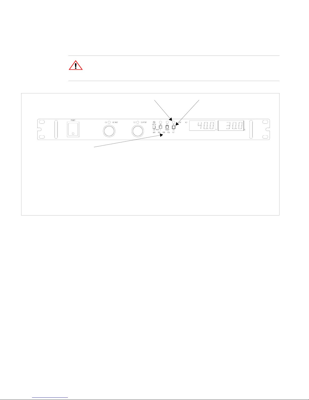
Remote Programming LEDs:
Local Switch (LOCAL)Remote LED (REM)
Address LED (ADR)
Indicates that the master controller is addressing the unit.
Service Request LED (SRQ)
Comes on at power up if the PON SRQ is set to on.
Error LED (ERR)
Indicates when a programming error has occurred. You
can clear the ERR LED with an error query command.
Fault LED (FLT)
Used to indicate AUX B status is TRUE.
Polarity LED (POL)
Used to indicate AUX A status is TRUE.
Figure 2.1 XFR and XHR Power Supply Front Panel with GPIB-M Interface
(XFR 1200 Watt model shown)
26 Operating Manual for Multichannel Functionality (GPIB-M)
Page 29
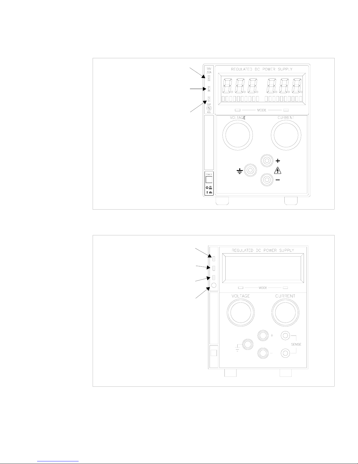
Service Request LED (SRQ)
Remote LED (REM)
Shutdown LED (S/D)
Installation and Configuration
Initial Inspection
Figure 2.2 XPD Power Supply Front Panel with GPIB Interface
Remote Mode (REM) LED
Service Request (SRQ) LED
Over Voltage Protection (OVP) LED
OVP Potentiometer
Figure 2.3 XT and HPD Power Supply Front Panel with GPIB Interface
Release 2.1 27
Page 30
Installation and Configuration
Initial Inspection
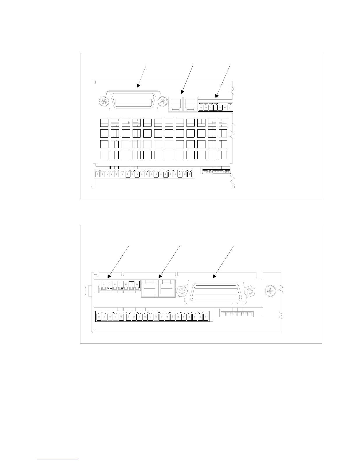
GPIB CANBUS USER LINES
1
Figure 2.4 XFR 2800 Watt Power Supply Rear Panel with GPIB-M Interface
CANBUS GPIBUSER LINES
1
Figure 2.5 XFR 1200 Watt Power Supply Rear Panel with GPIB-M Interface
28 Operating Manual for Multichannel Functionality (GPIB-M)
Page 31

Installation and Configuration
GPIB CANBUS USER LINES
Initial Inspection
Figure 2.6 XHR Power Supply Rear Panel with GPIB-M Interface
USER LINES
CANBUS
GPIB
Figure 2.7 XPD Power Supply Rear Panel with GPIB-M Interface
Release 2.1 29
Page 32

Installation and Configuration
!
Initial Inspection
USER LINES
CANBUS
GPIB
Figure 2.8 XT/HPD Power Supply Rear Panel with GPIB-M Interface
CAUTION
Use proper static control techniques to avoid damage to static-sensitive components
on the printed circuit board
30 Operating Manual for Multichannel Functionality (GPIB-M)
Page 33
Basic Setup Procedure
This procedure can be used as a quick reference for those familiar with the
configuration requirements for the GPIB-M interface as installed in the DC power
supply.
IEEE-488 Controller Connection
Connect the GPIB cable to the supply at connector on the rear panel. Use an
approved IEEE-488 connector and cable when connecting the GPIB Interface to
your IEEE-488 GPIB network. Refer to Figure 2.4, Figure 2.5, Figure 2.6 or
Figure 2.7.
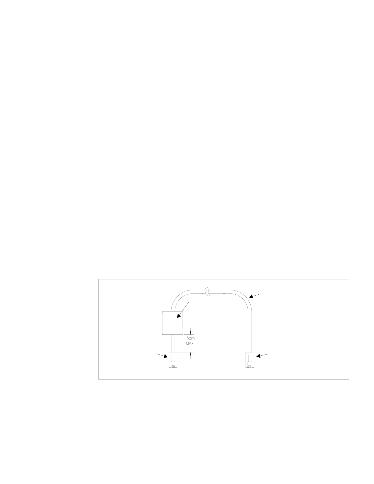
Add a ferrite block to reduce radiated emissions. The one inch square ferrite block
with built-in housing clip is packaged and shipped with the power supply interface
card.
To install the ferrite block:
1. Position the block no more than 5 cm (2 in.) from the power supply end of the
user cable.
Installation and Configuration
Basic Setup Procedure
2. Open the ferrite block housing.
3. Run the cable through the ferrite block. See Figure 2.9, “XFR GPIB Cable with
Ferrite Block” on page 31.
4. Close the housing clip.
The ferrite block ensures that the power supply system meets radiated emission
requirements for CE mark.
GPIB Cable
Ferrite Block
To p ow e r s u pp l y
GPIB connector
Figure 2.9 XFR GPIB Cable with Ferrite Block
To personal computer GPIB
connector
Release 2.1 31
Page 34

Installation and Configuration
Basic Setup Procedure
Setup
Procedure
For those who want more information, each step refers to more detailed procedures
located in subsequent sections.
1. Power ON
Power on the unit.
2. Configure Computer Controller
Configure the controller to match the power supply characteristics. The unit is
shipped with default GPIB address 2. Configure your controller to talk to
address 2.
3. Tes t
Test the link by communicating with the power supply.
Example: Send the ID query “*IDN?” and ensure you get a response. Send the
command ":VOLT 2;:CURR 1" to set voltage to 2V and current limit to 1A.
(Using IBIC
1
this would be ‘ibwrt ":volt 2;:curr 1"’)
See “Change Remote/Local Mode” on page 48 for information about changing
about Local/Remote modes.
4. Configure power supply
If desired, configure the power supply with the desired power on settings or a
different GPIB address. (Be sure to change the controller address to match.)
See “Power On Remo te State” on page 49, “Set Up Power ON Defaults” on page
56, and “Power On Output State” on page 57.
1. This text uses National Instruments' IBIC (Interface Bus Interactive Control) program commands
developed for their GPIB interface for computer controllers as examples only.
32 Operating Manual for Multichannel Functionality (GPIB-M)
Page 35

Installation and Configuration
!
Basic Setup Procedure
Table 2.1 Remote Mode Power On Conditions
Feature Factory Preset Value
Voltage setpoint 0.0V
Current setpoint 0.0A
Triggered voltage setpoint Disabled (DEFault)
Triggered current setpoint Disabled (DEFault)
Trigger source None
Low voltage setpoint limit 0.0V
High voltage setpoint limit 103% of voltage rating
Low current setpoint limit 0.0A
High current setpoint limit 103% of current rating
Over voltage protection Disabled (0.0V)
Under voltage protection Disabled (0.0V) and not shutdown when tripped
Over current protection Disabled (0.0A) and not shutdown when tripped
Power On
Service
Request
Under current protection Disabled (0.0A) and not shutdown when tripped
Fold shutdown protection None and delay 0.5s
AC OFF shutdown recovery Auto recover
OTP shutdown recovery Latched
Aux line configuration None and active low
CAUTION
Ensure the power supply chassis is properly connected to ground. The interface
connection system is not capable of handling the resulting excessive ground currents
that may flow through the connection to the controlling computer if the chassis is not
at ground potential.
The Power On Service Request setting causes the power supply to send a service
request to the computer controller when the power supply is turned on or when it
re-initializes after a momentary power interrupt if the following conditions are also
met:
• *PSC (power on status clear) is set to 0, and
• bit 5 in the Service Request Enable register has been set (*ESE) prior to power
off.
When a service request is sent, the front panel SRQ LED will also turn on. You can
clear the service request and turn off the SRQ LED by performing a serial poll. See
also “Status Byte” on page 79 for information about the SRQ command.
Release 2.1 33
Page 36

Installation and Configuration
Configure for GPIB Operation
Configure for GPIB Operation
The power supply is ready for GPIB communication when it leaves the factory, but
you may change any of the control settings. The default remote control setting is
GPIB, address 2.
Change
Remote
Control
Source
Set GPIB
Address
Select an interface for remote control.
SYST:REM:SOUR [GPIB|MCHannel]
where
• GPIB: control via GPIB interface
• MCHannel: multichannel operation using the CANbus interface
Change the GPIB address.
SYST:COMM:GPIB:ADDR <GPIB-address>
where
<GPIB-address> may be a value from 1 to 30.
Be sure to make a note of the GPIB address. If the address is unknown, use a feature
such as “Scan for Instruments” on National Instruments’ Measurement and
Automation Explorer.
34 Operating Manual for Multichannel Functionality (GPIB-M)
Page 37

Configure for Multichannel Operation
Installation and Configuration
Configure for Multichannel Operation
Multichannel
Connections
Multichannel
Configuration
You may remotely control up to 50 power supplies from one GPIB interface by using
multichannel addressing via the CANbus.
One power supply will be connected to a PC via GPIB. All other power supplies are
connected via CANbus (Controller Area Network) to that unit. SCPI commands that
include a channel address will be sent via the CANbus to the other power supplies.
(Commands with the local address will be executed locally and will not be sent).
The multichannel address must be appended to the program mnemonic. If no
multichannel address is appended to the program mnemonic, the command is
executed by the local (directly connected) power supply.
Each unit of the network can send and receive commands to and from other units on
the network. It is highly recommended that only one command be sent at a time. Any
GPIB timeout settings should be increased when using multichannel commands.
If a second power supply that has the same multichannel address as another is
connected to the bus, it will automatically increment its address until it finds a unique
address. If it fails to find a unique address, it will disconnect itself from the bus and
you will not be able to communicate with it until you disconnect the other power
supplies and cycle the power. Therefore, when configuring a network of supplies,
you can make all connections, and power on one supply at a time. They will
configure their addresses in the order that they were powered on. Be sure to note the
address of each power supply for future reference or in case you want to reorganize
the network.
Example:
Connect 3 power supplies for multichannel operation. You have one GPIB-M supply
and 2 CAN-only supplies. The GPIB-M supply's multichannel address is set to 1 at
the factory. Both CAN-only supplies are set to 2.
Connect all units as described in “Basic Setup Procedure” on page 31.
Power on the GPIB-M supply, then one of the CAN-only supplies. Check that you
can communicate with both. Send the *IDN? query to return the identification string
from the GPIB-M supply. Send "SYST2:IDEN?" to return the ID string from the
CAN-only unit.
Power on the last unit. Since multichannel address 2 already exists on the bus, it will
automatically configure itself to address 3. Check that this is the case by sending the
command "SYST3:IDEN?"
Release 2.1 35
Page 38

Installation and Configuration
Configure for Multichannel Operation
CANbus The CANbus port consists of two 4-pin modular “handset” jacks to support daisy
chain connections. The CAN (Controller Area Network) is an ISO standard
(ISO11898) for a serial communication network. Table 2.2 describes the pin
functions. The CANbus is used for communications in multichannel operation or
current sharing (master/slave) operation.
Table 2.2 CANbus Pins
Pin # Function
1CANLO
2 Ground
3CANHI
4 Ground
CANbus
Cables
Configuration
of CAN-only
Interface
Cards
The custom CANbus cables shipped with your unit are parallel 4-connector cables
with 4-pin modular “handset” connectors.
The CAN-only interface cards must be configured via the CANbus with another
GPIB-M card. The CAN-only interface cards are set to multichannel address 2 at the
factory. Ensure the multichannel address on the GPIB-M is set to an unused address,
for example, address 1. Connect the two power supplies as shown in Figure 2.10,
“Connections for Multichannel Operation” on page 37.
Send the query to the CAN-only power supply:
SYST2:REM:SOUR?
and ensure the response is “MCH” for multichannel.
If necessary, set the power supply to accept control via multichannel commands
(the CANbus interface) with the SCPI command:
SYST2:REM:SOUR MCH
Set each slave's unique multichannel address using the command:
SYST2:COMM:MCH:ADDR <multichannel-address>
where multichannel-address is an integer in the range of 1-50.
This procedure can be repeated separately with each power supply to assign a unique
address to each. Once all power supplies are configured, they can be connected to the
CANbus network.
Note See “Broadcasting Commands” on page 39 for additional information on
configuring CAN-only units.
36 Operating Manual for Multichannel Functionality (GPIB-M)
Page 39

Setup See Figure 2.10.
1. Connect power supplies to be controlled via the CANbus network. Connect the
power supplies in a daisy chain by linking the first power supply to the second
using one cable, and then the second to the third using a second cable and the
second CAN port. Continue making connections in this fashion until all the
power supplies are connected. Terminate the bus at both ends, using the unused
CAN ports, with 120 ohm, 1/4 Watt resistors (included) across the CAN HI and
CAN LO signals (Pins 1 and 3). See Table 2.2, “CANbus Pins,” on page 36.
2. At least one power supply must be connected to a PC via GPIB for multichannel
functionality. Configure each of the power supplies with a unique address, as
described in the configuration section. Addresses may be in the range 1 to 50
inclusive. Record the address of each unit for future reference.
3. Turn the power supplies on one at a time.
Installation and Configuration
Configure for Multichannel Operation
GPIB
Connection
Figure 2.10Connections for Multichannel Operation
Using
Multichannel
Once the power supplies have been configured and connected, you may power them
on.
Operation
Power supplies controlled via multichannel have full capabilities, including
changing REM/LCL modes and calibration.
Any power supply may send multichannel commands, if they are connected to a PC
via GPIB.
Release 2.1 37
Page 40

Installation and Configuration
Configure for Multichannel Operation
A power supply will attempt to connect to the network:
• on power up, and
• when the multichannel address is changed.
The power supply will successfully connect if there are no other power supplies on
the network with the same address.
Error 1702, “Multichannel address taken” is queued if the power
supply fails to connect.
SCPI Remote Control (RCONtrol) subregister will indicate the status of the
connection. A power supply that has been disabled will not have any bits set. Use the
SCPI command:
STAT:OPER:RCON:COND?
to query the condition of the multichannel interface.
See Table 4.5, “Remote CONtrol Sub-Register,” on page 74 for a description of the
bits in this register.
Multichannel
Commands
To send a command to a multichannel power supply, attach the channel address to
the command. If no channel number is specified, the command will be executed by
the directly connected power supply.
For example, the command:
SOURce12:VOLT 10.0
will set the power supply with address 12 to 10V output. The master receives the
command and puts in on the CANbus.
Appendix B. “SCPI Command Reference” lists all commands.
[<channel>]indicates where the multichannel address is to be inserted into the
command.
IEEE488.2 commands have been given an alias that is SCPI compliant if the
command is applicable to a power supply in multichannel operation. These
commands include *CLS, *IDN?, *OPT?, *RST, *TST?, *RCL, *SAV, *SDS, and
*WAI. See Table B.1, “IEEE 488.2 Commands,” on page 104.
Note The multichannel interface can not handle multiline response messages.
38 Operating Manual for Multichannel Functionality (GPIB-M)
Page 41

Installation and Configuration
Configure for Multichannel Operation
Broadcasting
Commands
You can specify a channel address of "0" to broadcast a command to all power
supplies connect via CANbus. Broadcast commands are useful in set up and
operation.
Example:
Set all power supplies to remote mode:
SYST0:REM:STAT REM
Turn output on:
OUTP0 ON
Set voltage output to maximum:
SOUR0:VOLT MAX
Attempting to broadcast any query will generate an error.
Note Broadcasting may be useful in configuring a CAN-only power supply when its
address is unknown. Connect the unit to a GPIB-M power supply. Broadcast the set
multichannel command to change the CAN-only supply's address. The command has
no effect on the GPIB controlled unit.
Example:
"SYST0:COMM:MCH:ADDR 2" will set the CAN-only unit to address 2.
Specifications
Note that there will be a lag in execution time between the local unit and all other
units of up to a maximum of 20 ms.
Max connected units 50
Max cable length 40 m
Bus speed 700 kbits/sec
Termination 120 ohm 1/4 W
Connectors
Addresses 1 to 50
modular handset 4-position, 4-contact jacks
Release 2.1 39
Page 42

Installation and Configuration
User Lines
User Lines
The user lines connector, located on the GPIB-M interface rear panel, provides
several signals to increase your operating control of the supply. These signals are
dependent on the operator's design and uses. The operation of the auxiliary status
lines requires that you provide external Vcc and ground. To locate the connector,
refer to Figure 2.4, Figure 2.5, Figure 2.6 and Figure 2.7. See Figure 2.13,
“Schematic For User Line Interface” on page 42 and Table 2.3, “User Line Pins,” on
page 40 for pin descriptions.
The user lines are optically isolated, open collector configuration. The input lines are
capable of sinking 10mA (with recommended 5V at input) up to a maximum of
90mA.
XT/HPD and XPD: The connector for the user lines is a standard 8-conductor RJ45
jack. The cable is supplied by the user.
XFR or XHR: The connectors are removable “wire clamp” terminal block style
connectors. Use shielded twisted pairs of 22-24 AWG wire for connections. Strip
0.2” (5mm) of insulation from the wires and clamp securely at the appropriate pin.
Table 2.3 User Line Pins
Pin # Function Input/Output
1 Aux Status Line A Output
2 Aux Status Line B Output
3 External Trigger 4-12V Input
4 Safety Interlock (Shutdown) 4-12V Input
5 Safety Interlock (Shutdown) GND) Input
6 User Power, 5-12Vdc Input
7 User Ground Input
40 Operating Manual for Multichannel Functionality (GPIB-M)
Page 43

User Lines
Connection
(XT, HPD,
XPD)
Installation and Configuration
User Lines
Figure 2.11User Signals Connector (XT, HPD and XPD)
Use a standard 8-connector RJ45 connector and data cable to connect to the user
lines.
Add a ferrite block to reduce radiated emission. The one inch square ferrite block
with built-in housing clip is packaged and shipped with the power supply interface
card.
To install the ferrite block:
1. Position the block no more than 5 cm (2 in.) from the power supply end of the
user cable.
2. Open the ferrite block housing.
3. Loop the cable through the ferrite block. See Figure 2.12, “XT, HPD, XPD User
Cable with Ferrite Block” on page 41.
4. Close the housing clip.
The ferrite block ensures that the power supply system meets radiated emission
requirements for CE mark.
J7 User Cable
Ferrite Block
To User Custom InterfaceTo J7 Connector
Figure 2.12XT, HPD, XPD User Cable with Ferrite Block
Release 2.1 41
Page 44

Installation and Configuration
S
User Lines
CHASSIS POTENTIAL ISOLATED USER LINES
CNY17-2
USER LINE
CNY17-2
508 Ohm
0.4W
CNY17-2
CNY17-2
Vf = 1.3V TYP, 1.5V MAX
If = 10mA Recommended, 90mA MAX
Figure 2.13Schematic For User Line Interface
508 Ohm
0.4W
42 Operating Manual for Multichannel Functionality (GPIB-M)
Page 45

Section 3. Operation
Overview
Once you have installed the power supply and connected both the AC input power
and the load as explained in Section 2, the power supply is in its default
configuration and is ready for operation.
One power supply must be connected via GPIB. Additional units may be controlled
via the CANbus port which enables multichannel addressing. The multichannel
addressing also supports the current sharing feature for parallel-connected units. Any
unit may be toggled between remote and local control modes.
Section 3 provides information about operating the power supply remotely via the
GPIB-M or CAN-only optional interface.
In addition, brief descriptions are provided of Constant Voltage and Constant Current
modes. See “Power Supply Operation” on page 48.
Powering ON
the Power
Supply
WARNING- Shock Hazard
The factory setting for Power ON is 0V and 0A with the output OFF. These settings
can be customized by end users. If you suspect that the power supply has been used
by someone else since it was received from the factory, be prepared for the unit to
power ON with a live DC output.
To power on the power supply:
1. Ensure that the AC power switch is OFF.
2. Connect the unit to an AC outlet.
3. Turn on the front panel AC power switch.
After a short power-on delay, the digital meters on the front panel and the CV LED
illuminate.
Release 2.1 43
Page 46

Operation
Power Supply Operating States
Power Supply Operating States
The power supply has 5 operating states:
• Power-On
• Output Shutdown
• Soft Start
• Normal Operation
• Calibration
Power-On This is the period between the time that AC power is applied to the supply (AC
breaker turned on) and the time that the power supply is ready for operation. During
this period, the internal circuits are powering up and performing self-tests. At the end
of the Power-On period, the supply is normally in its default Power-On mode with
the output OFF, V
SET
=0 and I
SET
=0.
Output
Shutdown
In this state, the output is disabled and there is no output regardless of power settings.
The power supply can be placed in the Output Shutdown state by a command (or the
the front panel - XFR, XHR only), via the Interlock signal, or from a protection
mechanism. This is also called the Standby mode.
Soft Start In this state, the output power is ramping up gradually towards its target load. This
reduces equipment stress. This state occurs whenever the supply output is enabled
by the software (a command or a protection is cleared), and is approximately 2
seconds in duration. See “Slew Rate” on page 67 to change the properties of the
ramp.
Normal
Operation
This is the normal operating state for the power supply. The power supply is ready
to accept commands.
Calibration This is a service mode that is used to calibrate setpoints and readback levels for
accuracy. Calibration should only be performed by qualified service personnel.
44 Operating Manual for Multichannel Functionality (GPIB-M)
Page 47

Power Supply Regulation Modes
The power supply has 2 regulation modes while in the Normal Operation State:
• Constant Voltage (CV)
• Constant Current (CC)
The CV, CC LEDs on the front panel indicate the regulation mode.
Operation
Power Supply Regulation Modes
Constant
Voltage (CV)
Constant
Current (CC)
Automatic
Mode
Crossover
In this mode, the supply’s output voltage is constant while the current and power
vary with the load. The power supply will operate in constant voltage mode
whenever the load current I
(I
L=VSET/RL
). In constant voltage mode, the power supply maintains the output
is less than the current limit setting I
L
voltage at the selected value (V
) while the load current IL varies with the load
SET
, or: IL<I
SET
SET
.
requirements.
In this mode, the supply’s output current is constant while the voltage and power
vary with the load. The power supply will operate in constant current mode
whenever the load resistance is low enough that the load current I
current limit setting I
maintains the output current at the selected value (I
SET
. (VL=I
SETRL
). In constant current mode, the power supply
) while the load voltage VL
SET
is equal to the
L
varies with the load requirements.
This feature allows the power supply to automatically switch operating modes in
response to changing load requirements. If, for example, the power supply was
operating in Constant Voltage (CV) Mode (I
load current (I
) became EQUAL TO the current limit setting (I
L
L
< I
), and the load changed so the
SET
), the power
SET
supply would automatically switch into Constant Current (CC) Mode and the output
voltage would vary in response to changes in load current. If the additional load was
subsequently removed so the load current was again LESS THAN the current limit
setting, the supply would automatically return to Constant Voltage (CV) Mode.
Release 2.1 45
Page 48

Operation
Remote Control Modes
Remote Control Modes
The power supply must be in remote mode to execute commands. The remote mode
is indicated by the front panel remote status LED. A power supply will respond to
queries when in local mode, but will generate an error when a command is received.
GPIB equipped supplies will automatically transition from local to remote mode when
any command data is received. CANbus-only supplies may have to be put into remote
mode with a command before sending any other command. See “Change
Remote/Local Mode” on page 48.
The factory default power-on settings are given in Table 3.1, on page 46.
Table 3.1 Power Supply Factory Defaults
Power Supply Default Remote State
XFR or XHR Remote OFF
XPD Local ON
XT or HPD Local ON
Default Output State
(Shutdown)
You can change the default Remote/Local state, see “Power On Remote State” on page
49.
If safety is an issue because the front panel control knobs may be set to hazardous
voltages at power on, contact the factory to order locking bushings for the knobs.
See your power supply’s operating manual for details on using the power supply in
local mode.
46 Operating Manual for Multichannel Functionality (GPIB-M)
Page 49

Front Panel LEDs
The status LEDs on the front panel give an instant indication to the status of the
power supply.
LED Description
REM Unit is operating under remote control. Remote settings apply.
SRQ Unit is requesting service
S/D Unit is in shutdown due to tripped protection mechanism,
In addition, the XFR and XHR series power supplies have the following additional
indicators.
LED Description
ERR Unit has encountered an error
Operation
Front Panel LEDs
command, or interlock
ADR Unit is receiving a command
OVP Unit is shutdown due to a hardware over-voltage condition.
OTP Unit is shutdown due to an over-temperature condition.
ACF Unit is shutdown due to an AC input failure condition (AC line may
be high or low.)
POL Used to indicate the AUX A status condition is true.
FLT Used to indicate the AUX B status condition is true.
Release 2.1 47
Page 50

Operation
Power Supply Operation
Power Supply Operation
This section describes how to configure and operate the power supply.
For a complete list of commands and remote functionality, see Appendix B. “SCPI
Command Reference”. Read “Understanding SCPI Commands” on page 99 for a
better understanding of SCPI commands.
Almost every command setting can be queried to return the current setting. The
query is given by appending a “?” to the command header (the command, minus any
parameters).
Change
Remote/Local
Mode
A SCPI command is provided to change the remote/local mode. (GPIB can also use
IEEE 488-1 functions to change modes.)
SYST:REM:STAT {LOC|REM|RWL}
Where:
• LOC: go to local mode operation
• REM: go to remote mode operation
• RWL: remote with local lockout. Go to remote mode operation with local mode
locked out. With RWL set, the user cannot return to local mode via the front
panel. RWL is only valid for XFR/XHR series power supplies. Local lockout
will not allow the user to return the power supply to local operation using the
front panel LOCAL button.
To query to remote mode:
SYST:REM:STAT?
XFR and XHR series power supplies have a LOCAL key that allows you to shift
control to local mode except if the power supply has Local Lockout (LLO) active.
Changing the remote/local state:
When entering local mode, the option card will clear all protections and re-enable the
bridge since software protections cannot be cleared at the front panel. When
returning to remote, the command shutdown will be reasserted if it was set when the
unit was last in remote mode.
Software protection settings and configurations (over voltage, under voltage, over
current and under current levels, and AC Fail, over temperature and fold
configurations) are ignored while in local mode.
48 Operating Manual for Multichannel Functionality (GPIB-M)
Page 51

Operation
Power Supply Operation
The functionality of the hardware protection circuits (OVP, OTP, ACFail) remains
the same in local mode.
WARNING
When returning to remote mode, the remote protection setpoints may trip even
though the remote setpoints would not normally cause the unit to shutdown. This
is because the output transient in settling to the remote settings from the local
settings may cause a trip condition. Once cleared, the unit will operate normally.
Note: There will be no status reporting of OVP, interlock, sense, OT or AC protections
while the unit is in local mode since software protections cannot be cleared at the front
panel.
Power On
Remote State
Enable
Output
Set Voltage
and Current
(XFR/XHR and XPD only) You may set whether the power supply powers on in
remote or local mode
SYST:REM:PON:STAT <on-off-state>
When the output is disabled, the S/D LED on the front panel will be lit and a bit in
the shutdown register will be set.
To enable or disable the output:
OUTP[<channel>] {ON|OFF|0|1}
Setting the output state to "ON" will attempt to clear all shutdown bits (except the
interlock). Previously, it only cleared a shutdown caused by a command (i.e. "OUTP
OFF").
To query the state of the output enable:
OUTP?
The output state query returns "0" if the output is disabled for any reason (e.g.
protection tripped or command shutdown) and "1" only if the output is enabled.
SOUR:VOLT <voltage>
SOUR:CURR <current>
To check your settings:
SOUR:VOLT?
SOUR:CURR?
Release 2.1 49
Page 52

Operation
Power Supply Operation
Readback To check the voltage or current output of the power supply, use the commands:
MEAS:VOLT?
MEAS:CURR?
Units are in volts and amps, respectively.
Example:
To set voltage to 5.5V and current limit to 100A, send the command:
:VOLT 5.5; :CURR 100
Then check the output:
MEAS:VOLT? 5.500 (example readback, default unit V)
MEAS:CURR? 0.010 (example readback, default unit A)
50 Operating Manual for Multichannel Functionality (GPIB-M)
Page 53

Operation
Power Supply Operation
Configure
Output
Protection
Five configurable protection mechanisms are available:
• OVP: Over-Voltage Protection. Factory default = 0V (disabled)
• UVP: Under-Voltage Protection. Factory default = 0V (disabled)
• OCP: Over-Current Protection. Factory default = 0A (disabled)
• UCP: Under-Current Protection. Factory default = 0W (disabled)
• Fold: Fold Protection. (See below.)
OVP shuts down the power supply if the protection limit is exceeded. The other
options offer a choice: they shut down the power supply or issue a warning by setting
a bit in the status register. Set the protection mechanism to ON to enable it to
shutdown the power supply.
When the protection level is set to zero, that mechanism is disabled. However, in the
case of OVP, a fixed hardware protection mechanism still exists to protect the supply
from damage.
To set the over-voltage protection level:
SOUR:VOLT:PROT <voltage>
To set the under-voltage protection level:
SOUR:VOLT:PROT:UND <voltage>
To enable UVP shutdown:
SOUR:VOLT:PROT:UND:STAT <on-off-state>
To set the over-current protection level:
SOUR:CURR:PROT <current>
To enable OCP shutdown:
SOUR:CURR:PROT:STAT <on-off-state>
To set the under-current protection level:
SOUR:CURR:PROT:UND <current>
To enable UCP shutdown:
SOUR:CURR:PROT:UND:STAT <on-off-state>
To check if a protection mechanism was tripped:
SOUR:VOLT:PROT:OVER:TRIP?
SOUR:VOLT:PROT:UND:TRIP?
SOUR:CURR:PROT:OVER:TRIP?
SOUR:CURR:PROT:UND:TRIP?
Alternatively, you can query the status register. See Appendix B. “SCPI Command
Reference”.
Release 2.1 51
Page 54

Operation
Power Supply Operation
OVP The over voltage protection level is set with a command for remote mode and with
the front panel potentiometer for local mode. If operating in remote mode, and the
OVP is disabled by setting the trip level to 0, a second hardware OVP circuit, fixed
at approximately 115%, may trip and shutdown the unit. If this occurs, either
shutdown the unit, or toggle the output with a command, the interlock or front panel
S/D button to clear the OVP circuit.
OVP operation will remain the same for local mode. Specifically, it will be
controlled via the front panel potentiometer. The OVP LED will indicate if OVP has
been tripped. Either pressing the S/D button, or asserting the interlock will clear the
OVP condition and the unit resumes normal operation when the respective signal is
removed.
Fold
Protection
Fold Mode protection will shut the power supply down when the unit enters the
selected regulation mode for a specified period of time.
A programmable delay time causes the supply to wait before shutting down the
output.
To set the fold mode:
OUTP:PROT:FOLD {CC|CV|NONE}
Where:
• NONE indicates fold protection is disabled.
• CC indicates the supply will shut down due to constant current condition.
• CV indicates the supply will shut down due to constant voltage.
The default value is NONE.
To set the fold delay:
OUTP:PROT:FOLD:DEL <delay_time>
Where:
<delay_time> is a value in the range of 0–60 seconds.
Units may be specified as “ms” (milliseconds) “s” (seconds), or “min” (minutes). If
no units are specified, the default seconds are assumed. (Increments of 0.1s are
allowed.) The default value is 0.5 second.
52 Operating Manual for Multichannel Functionality (GPIB-M)
Page 55

Operation
Power Supply Operation
Additional
Protections
Set
Shutdown
Recovery for
AC Off
AC Off
Protection
Other protection mechanisms designed to protect the power supply are:
• AC Off: Disables the output if the AC line drops below the acceptable range.
• Sense Protection: Disables the output when the internal sense circuit is tripped
by either reversed polarity at the output of the supply or a high voltage present
at the output.
• Output Fail: Disables the output if the bridge circuit fails. This is a hardware
protection circuit and has no associated software controls.
There are two options for AC Off (ACO) and Over-Temperature protection (OTP):
• Auto-Recovery: With this method, the power supply returns to its normal
operating state once the alarm condition no longer exists. For example, if there
was an over-temperature alarm and the protection was set to auto-recovery, the
power supply would return to its normal operating state once the temperature
was reduced below the alarm level.
• Latched: With this method, the power supply remains in Shutdown state until
the operator manually clears the protection and manually turns the output back
on.
The user has the option of setting whether the AC Off protection mechanism is
latched or automatically resumes operation.
Over
Temperature
Protection
SENSe:VOLT:AC:PROT:LATCH {ON|1|OFF|0}
Where:
• ON or 1 means the supply will be latched in shut down if an AC Off condition
occurs, until the user re-enables the output, and
• OFF or 0 means the supply will automatically resume operation when the AC
line input returns to normal.
The default value is OFF.
To query if AC Off has tripped:
SENSE:VOLT:AC:PROT:TRIP?
The user has the option of setting whether the OTP mechanism is latched or
automatically resumes operation.
SENSe:TEMP:PROT:LATCH {ON|1|OFF|0}
The default value is ON.
To query if OTP has tripped:
SENSE:TEMP:PROT:TRIP?
Release 2.1 53
Page 56

Operation
Power Supply Operation
Clear
Protection
Event
Shutdown vs
Protection
Alarm
If the unit has shut down, resume operation by sending the "OUTP ON" command.
To support older revisions of firmware (1.5 and older),
[:]OUTPut[<channel>]:PROTection:CLEar command will still be
parsed and passed to other instruments on the CANbus.
WARNING- Fire Hazard
If an over-voltage or over-current protection error persists without apparent cause,
disable the output, and turn the AC switch OFF. Inspect the load and power supply
for evidence of an electrical fault. The power supply should not be brought back into
operation if there is any evidence of an electrical fire or other safety hazards.
If a protection setpoint is exceeded, the system does the following:
1. If :STATe has been set to ON, the unit shuts down.
(OVP does not have a settable :STATe. It is always ON.)
2. If :STATe has been set to OFF, the unit does not shut down but creates an alarm
by setting the appropriate bit in the questionable status register, which can be
queried remotely. See “Status Registers” on page 69 for more information.
54 Operating Manual for Multichannel Functionality (GPIB-M)
Page 57

Operation
Power Supply Operation
User Settings
(Save and
Recall)
If you have a frequent or constant need for a specific voltage and current output, you
can save these setpoints in the power supply’s memory as a user setting. Once a
setting is stored, it remains in the power supply’s memory after the unit is powered
off.
Ten user setting memory locations are available, and each saves the following
parameters:
• Voltage setpoint
• Current setpoint
• Over-voltage protection setpoint (OVP)
• Under-voltage protection setpoint and shutdown configuration (UVP)
• Over-current protection setpoint and shutdown configuration (OCP)
• Under-current protection setpoint and shutdown configuration (UCP)
• Foldback protection mode and delay settings
• AC Off auto recovery configuration (ACO)
• OTP auto-recovery configuration
• Aux line configuration
• Voltage and current soft limits
• Triggered setpoints and trigger source
Note All parameters are saved and used when the user setting is recalled. Therefore, you
should set parameters that you do not care about to the factory defaults.
To store (save) settings:
*SAV <user-setting>
or the SCPI equivalent for multichannel addressed units
SYST<channel>:SAVE <user-setting>
where <user-setting> is an integer from 1 to 10.
Example:
*SAV 1 will save all the present settings to user setting location 1.
To recall settings:
*RCL <user-setting>
To save default settings:
*SDS <user-setting>
Release 2.1 55
Page 58

Operation
Power Supply Operation
This will save factory default settings to a user setting location, replacing any setting
that was previously saved there.
Example:
To save settings, set up the power supply with all required settings (we recommend
that you do this right after recalling the factory default settings).
For example, you can set voltage, current, and all protection levels.
Then to save the settings to Location 1: issue the command *SAV 1
When you want to recall the settings, issue the command *RCL 1. If you want to
recall them at the next power on, issue the command OUTP:PON:REC USER1
To change a stored setting, overwrite it with a new setting.
Set Up Power
ON Defaults
You can change the power supply to power on with setpoints other than the factory
defaults.
Use the command:
OUTP:PON:RECall [PRESet|USER <user-setting>|ASEQ
<sequence-number>]
where the 4 options are:
• PRESet: The output is reset to the original factory levels at power on. (default)
• USER <user-setting>: The output is set to a custom setting recalled from
memory. This assumes that at least one user setting has been set up and stored in
memory. See “User Settings (Save and Recall)” on page 55.
• ASEQ <sequence-number>: Recall a stored program. A RUN command must
be issued to start running the program. This assumes that at least one program
has been created and stored in memory. See “Auto Sequencing” on page 60 for
information about remotely programming and running auto sequence programs.
Example:
To power on user setting #1:
OUTP:PON:REC USER1
The user setting must be in the range of 1–10. See “User Settings (Save and Recall)”
on page 55 for an explanation of how to save user settings.
56 Operating Manual for Multichannel Functionality (GPIB-M)
Page 59

Operation
Power Supply Operation
Power On
Output State
Reset Resetting the unit puts certain features to a known state. These states are listed in
(XFR/XHR only) You may also change the output state whether the output is enabled
or disabled at power on.
To change the power on at output state:
OUTP:PON:STAT [ON|OFF|1|0]
Whether the unit powers on with output enabled is a function of both the state at
power off and this setting.
Table 3.2.
To reset the unit:
*RST or SYST:RES
Table 3.2 Features Affected by Reset (*RST) Command
Feature Reset State (*RST)
Voltage setpoint 0.0V
Current setpoint 0.0A
Low voltage setpoint limit 0.0V
High voltage setpoint limit 101% of voltage rating
Low current setpoint limit 0.0A
High current setpoint limit 101% of current rating
Over voltage protection Disabled (0.0V)
Under voltage protection Disabled (0.0V) and not shutdown when tripped
Over current protection Disabled (0.0A) and not shutdown when tripped
Under current protection Disabled (0.0A) and not shutdown when tripped
Fold shutdown protection None and delay 0.5s
AC off shutdown recovery Auto recover
OTP shutdown recovery Latched
Triggered voltage setpoint Disabled (Default)
Triggered current setpoint Disabled (Default)
Autosequence mode Exit
Calibration mode False
Output Disabled
Release 2.1 57
Page 60

Operation
Power Supply Operation
Read Error
Messages
The error queue holds up to 50 error messages. Once each message has been read, it
is cleared from the system.
To read from the error queue:
SYST:ERR?
This command returns an error code and message from the error queue. For example:
• -315, “Configuration memory test”
• -100, “Command error”
• 0, “No error”
See Appendix C. “Error Messages” for descriptions of the messages.
Clear Status Issue a Clear Status command to clear all error messages and status registers.
*CLS
or
STATus<channel>:CLEar
Configure
Auxiliary
Status Lines
The Auxiliary (Aux) lines are 2 open collector outputs that can be used to monitor
the status of the power supply. The auxiliary lines are referred to as AUX A and AUX
B. The auxiliary status lines can be set up to report the following status conditions:
• NONE
• ON: Output On
• OFF: Output Off
• OVOLtage: Over-Voltage Condition
• UVOLtage: Under-Voltage Condition
• OCURrent: Over-Current Condition
• UCURrent: Under-Current Condition
• FOLD: Fold Protection Tripped
• CC: Constant Current Mode
• CV: Constant Voltage Mode
• UNRegulated: Output Unregulated
• OTEMperature: Over Temperature Protection Tripper
• ACOFf: AC Protection Tripped
• SPRotection: Sense Protection Tripper
58 Operating Manual for Multichannel Functionality (GPIB-M)
Page 61

Operation
Power Supply Operation
To set up Auxiliary line A:
OUTP:AUXA:SOUR <aux-line-mnemonic>
To set up Auxiliary line B:
OUTP:AUXB:SOUR <aux-line-mnemonic>
The choices for <aux-line-mnemonic> are listed above.
To check the state of the line:
OUTP:AUXA:STAT?
OUTP:AUXB:STAT?
This command returns a 1 or 0. If it returns a 1, this means that the status selected as
the auxiliary line mnemonic is true.
The XFR and XHR series power supplies use the polarity (POL) LED and fault
(FTL) LED to indicate is the AUX A and AUX B status conditions are true.
Release 2.1 59
Page 62

Operation
!
Auto Sequencing
Auto Sequencing
Auto Sequencing allows users to program a sequence for automated operation. Up
to 10 programmable sequences may be stored with up to 99 steps per sequence. Each
step can be programmed to set the voltage setpoint, current setpoint, and OVP level.
The steps are either programmed to run for a specific length of time or are
programmed to pause and wait for a trigger input before continuing. The duration of
each step may range from 10 ms to 99 hours.
Each sequence can be programmed to run a set number of repetitions or indefinitely.
If the sequence contains steps that advance by a trigger event, a single trigger source
can be selected to advance those steps.
CAUTION
Setpoint limits do not apply to auto sequence programmed setpoints.
Programming
a Sequence
Users can select and start a sequence, and while the sequence is running, pause or
end it at any time. Users can also skip to the next step at any time.
Commands are also available to let users run, pause, resume, and restart an
autosequence. A pause, or wait for trigger, causes the power supply to hold the
output at the programmed level until the appropriate signal to continue is received.
Select Sequence to Program
Using the following command, select a sequence that you want to work with.
Sequences are identified with a number from 1 to 10.
PROGram:NAME <sequence_number>
<sequence_number> is a number between 1 and 10 that corresponds to the
number of the sequence.
If <sequence_number> already exists, then that existing program is selected. If
the program name does not exist, then the new name is selected, but no program is
defined by this selection.
60 Operating Manual for Multichannel Functionality (GPIB-M)
Page 63

Operation
Auto Sequencing
Editing the Sequence
To edit an existing step or to program new steps, use the following commands:
PROG:STEP<step_number>[:EDIT] [[[[<voltage>]
,<current>],<OVP_level>],{<time>|TRIG}]
Any of the step parameters may be omitted, in which case the default parameters will
be used. The default values for a step are 0 V, 0 A, 0 V, 10 ms.
Example:
PROG:STEP1 10,10
PROG:STEP2 20,20,,20
will program step 1 to be 10V, 10A, OVP disabled (0V) and 10ms in duration and
step 2 to be 20V, 20A, OVP disabled and 20 seconds in duration.
To insert a step between commands in an existing program, use this command:
PROG:STEP<step_number>:INS [[[[<voltage>]
,<current>],<OVP_level>],{<time>|TRIG}]
The step number is where the inserted step is to be located. The existing step and all
following steps at that location are moved down.
In both the edit and insert commands:
• <step_number> ranges from 1 to 99.
• <time> defines the duration of the step and may be given in the following
fomats:
hh:mm:ss.s hours/minutes/seconds
mm:ss.s minutes/seconds
<floating point number>H hours
<floating point number>M minutes
<floating point number>S seconds
<floating point number> seconds
Ranges from 10ms to 99 hours.
• TRIG may be entered instead of a step duration. In this case, the unit will hold
the output levels at that step until a trigger signal is supplied.
Release 2.1 61
Page 64

Operation
Auto Sequencing
Setting Sequence Repetitions
Set the number of times a sequence will repeat before stopping execution.
PROG:REP {ONCE |<sequence_count>|FOR|INF}
• ONCE will run the sequence once and return it to its STOP condition.
• <sequence_count> ranges from 1 to 9999. It will run the sequence the
number of times specified before putting it into the STOP condition.
• FORever and INFinity cause the sequence to repeat forever. A query will return
9.9E37, representing INFinity.
Selecting a Trigger Source
If any triggers are programmed into the sequence, select a trigger source:
PROG:TRIG:SOUR {BUS|MAN|EXT|IMM}
• BUS - trigger signal is IEEE 488.1 GET or *TRG
• MANual - trigger input is from the front panel TRIGGER key
• EXTernal - The external trigger line is selected as the source.
• IMMediate - The source is the SCPI command “INIT:IMM”
Editing Step Parameters
Commands are provided to edit only one of voltage setpoint, current setpoint, OVP
level, step duration, or end action.
• Program step voltage: PROG:STEP<step_number>:VOLT <voltage>
• Program step current: PROG:STEP<step_number>:CURR <current>
• Program step OVP level: PROG:STEP<step_number>:OVP
<OVPlevel>
• Program step time (duration): PROG:STEP<step_number>:DWEL
{<time>|TRIG}
Deleting Steps
To delete any step from the sequence:
PROGram:STEP<step_number>:DELete
Subsequent steps are shift up.
Note The default value for a sequence’s repeat time and trigger source is repeat once and
trigger from key. See “Setting Sequence Repetitions” on page 62 and “Using Auto
Sequencing” on page 63
62 Operating Manual for Multichannel Functionality (GPIB-M)
for an explanation of how to edit these values.
Page 65

Querying the number of steps
To query the number of steps that have been programmed:
PROGram:STEP:COUNt?
Operation
Auto Sequencing
Deleting a
Sequence
Using Auto
Sequencing
Deleting Sequences
If you no longer need a sequence, select it with the PROG:NAME command and then
delete it with the following:
PROGram:DELete
You can also use the following to delete all sequences:
PROGram:DELete:ALL
Auto Sequence programs can be set to run as a Power ON default or recalled from
memory.
Auto sequence programs can operate 3 different ways:
• They can run automatically through a series of steps, repeating those steps a
pre-set number of times if necessary, and complete their operation without
intervention from an operator.
• They can run automatically and be paused. If you need to stop the program
temporarily, change its state to “PAUS E” to stop it, and then change the
program’s state to “RUN” to resume the program’s operation when ready. The
output remains on and voltage may be present at the output.
• They can run automatically programmed to wait for a trigger at certain points in
the sequence. If you want the program to resume, you can supply a trigger signal
to the rear panel Trigger input.
Select Sequence to Run
To run an auto sequence program, first select the program you wish to run:
PROGram:NAME <sequence_number>
where <sequence_number> can range from 1 to 10.
Release 2.1 63
Page 66

Operation
Auto Sequencing
Operation
To run, stop or pause a sequence, use the following command:
PROGram:STATe [RUN|PAUSe|STOP]
• Once the programmed sequence has been selected, you can start it by setting the
state to RUN, by sending the command PROG:STAT RUN.
• At any time you can pause the sequence by sending PROG:STAT PAUS.
A paused sequence will cause the supply to hold the output levels at the setpoints
programmed by the current step. To resume, set the state to RUN again.
• To end the sequence operation, send the command PROG:STAT STOP.
Sending RUN will restart the auto sequence program from the first step.
• You can query the state of the selected auto sequence program with
PROG:STAT?
Trigger
If the auto sequence was programmed to wait for a trigger, the power supply holds
the output levels at the programmed setpoints until a trigger is received. It then
advances to the next step. A trigger must come from the selected trigger source,
which may be the GPIB bus, a SCPI command or the user lines.
Skipping a Step
To advance the sequence to the next step, send the command:
PROGram:STEP:NEXT
Querying Operation
You can query the step number that is currently operating:
PROGram:STEP:EXEC?
You can also query the number of times the sequence has executed:
PROGram:REP:EXEC?
Exiting Auto Sequence Operation
To exit auto sequence operation and return to normal operation, send the command:
PROGram:EXIT
64 Operating Manual for Multichannel Functionality (GPIB-M)
Page 67

Operation
Auto Sequencing
Set V, I, and P
Limits
Triggered
Setpoints
The voltage, current and power setpoints can be limited to less than the supply rating
range to match the tolerance of connected equipment or any other criteria you may
have.
Once the limits have been changed from the supply’s default rated output, settings
outside this range are no longer accepted.
Note Setpoint limits do not apply to the triggered outputs and auto sequence outputs.
To set the voltage limits:
SOUR:VOLT:LIM:HIGH <voltage>
SOUR:VOLT:LIM:LOW <voltage>
To set the current limits:
SOUR:CURR:LIM:HIGH <current>
SOUR:CURR:LIM:LOW <current>
If the high end of the range was set to 5 volts, the command, SOUR:VOLT 10 would
return an error.
To set a triggered setpoint:
SOUR:VOLT:TRIG <voltage>
SOUR:CURR:TRIG <current>
See “Triggering Commands” on page 66 for more information.
Release 2.1 65
Page 68

Operation
!
Auto Sequencing
Triggering
Commands
Triggers are event-driven signals that instruct power supplies to change their output.
Triggering provides a method to control changes in the power supply’s output and to
program several power supplies to react at the same time. Triggering is useful in
manufacturing processes where power requirements change as the machinery
performs different operations.
CAUTION
Setpoint limits do not apply to triggered setpoints.
To program triggers:
1. Configure the desired output levels as a result of a trigger.
:VOLT:TRIG {<voltage>|MAX|MIN|DEF}
:CURR:TRIG {<current>|MAX|MIN|DEF}
The user can choose to set both or just one of voltage or current triggered levels.
DEF (DEFault) means that when a trigger is received, no change will occur.
2. Specify a trigger signal source.
TRIG:SOURce {BUS|EXT|IMM|NONE} Where:
• BUS means the trigger source is the IEEE 488.1 GET or “*TRG”
• EXT means the source is the external trigger line. See “User Lines” on page
40
• IMM means the trigger source is the SCPI command INIT:IMM
• NONE means triggering is disabled.
66 Operating Manual for Multichannel Functionality (GPIB-M)
Page 69

Operation
!
Auto Sequencing
Slew Rate The slew rate is calculated as a function of change in the output voltage and a given
time interval. The maximum slew rate is 1% rated voltage/150us. The slew rate is
saved upon power off and restored at power on. Output ON/OFF and shutdown are
not affected by the programmable slew rate. These functions have a slew rate of
1%/20ms.
The range of output voltage is 5% - 0.1% of rated voltage.
The range of time interval is 1.5 s - 150 us.
The negative slew rate is limited by the discharge rate of the output capacitors.
During current share, slaves operate with their default slew rate. The master operates
at its programmed slew rate. Hence a programmable slew rate for the system is
achieved. However, this slew rate is limited by the speed of the control loop. The
slaves will return to their programmed slew rate when they exit current share slave
operation.
The slew rate error increases as the slew rate increases.
The SCPI commands for changing the voltage slew rate are:
:VOLT:SLEW:STEP {<slewrate-voltage> | MAX | MIN | DEF}
where voltage-step has the units V, mV, etc.
and the range is 0.1% to 5% of rated voltage for the power supply.
default step is 0.1% of rated output voltage.
query returns value in volts.
:VOLT:SLEW:INTerval {<slewrate-interval> | MAX | MIN | DEF}
where time interval has the units s, ms, or us
and the range is 150 us to 1.5s
default interval is 150us.
query returns value in volts.
CAUTION
Check both the voltage step and the interval to ensure you get the required slew rate.
Selecting DEFAULT for both settings will return the slew rate to the default value
of 1% rated voltage per 150us.
The combination must not exceed 1%/150us. Though the software will attempt to
achieve higher slew rates, it is limited to this value by hardware constraints.
Manufacturer's recommendation is to keep the slew rate at or below the default
value.
Release 2.1 67
Page 70

Operation
Auto Sequencing
Example:
Set a slew rate of 100V/10s for a 100V-60A power supply. This slew rate is 1V/0.1s,
which is within the acceptable range.
Send the commands:
“:VOLT:SLEW:STEP 1”, and
“:VOLT:SLEW:INT 100ms”
Using smaller steps will result in a smoother curve.
Identification
Query
Option
Identification
Query
SCPI Version
Query
The identification query command returns a string that states the manufacturer,
model, serial number, and firmware revision.
*IDN?
may return “Xantrex, XFR 10-120, 100000, 3.000/0/0/0000.
*OPT?
or
SYST<channel>:OPTion?
The option identification query returns a string listing any reportable options that are
installed in the power supply. Reportable options are GPIB and CANbus, but may
include others in the future. A zero will be returned if no options are installed.
Example:
*OPT? may return "GPIB, CANBUS" to indicate that both the GPIB and CANbus
(Multichannel/Current Share) options are installed.
SYST:VERS?
will return the SCPI version to which the unit complies (for example 1997-0).
68 Operating Manual for Multichannel Functionality (GPIB-M)
Page 71

Section 4. Status Registers
Overview
The Status Register structure is mandatory for SCPI and IEEE 488.2 compliance.
The register bits are defined by the SCPI and IEEE 488.2 standards.
Each status register has a Condition, Event, and Enable register and transition filters.
See “Status Register Commands” on page 81 for commands to read or change their
values.
Condition
Register
Event
Register
Enable
Register
Transition
Filters
Transitions of the condition register are automatic and reflect the condition of the
instrument at the moment. Reading a condition register has no effect on the contents.
The event register bits are set automatically to correspond with changes in the
condition register. The rules are dependent on the positive and negative transition
registers. Reading an event register clears it. The *CLS command clears all event
registers.
The enable register enables reporting of the event bits to the summary bit or the status
byte. The contents of the enable register are unchanged by *CLS and *RST.
A positive transition filter allows an event to be reported when a condition changes
from false to true. Setting both positive and negative filters to TRUE allows an event
to be reported any time the condition changes. Clearing both filters disables event
reporting.
The contents of transition filters are unchanged by *CLS and *RST.
The status registers maybe be divided into 4 categories, the operation status registers,
the questionable status registers, the standard event status register and the status byte.
The default setting for all transition filters is to report only positive (FALSE to
TRUE) transitions.
OPERation
Status
Register
Release 2.1 69
The operation status register is a 16-bit register which contains information about
conditions which are part of the power supply’s normal operation.
Page 72

Status Registers
Overview
The Operation Status data structure has the operation status register and 5
sub-registers to represent regulation, shutdown, protection shutdown, remote
control, and current sharing modes. Each of the sub-registers is summarized in a
summary bit.
Figure represents the Operation Status data structure. The “+” represents the logical
summation of bits in a register. Table 4.1, Table 4.2, Table 4.3, Table 4 .5, and Table
4.6 describe the meanings of each bit as well as the bit number and bit weight.
70 Operating Manual for Multichannel Functionality (GPIB-M)
Page 73

Status Registers
Overview
Over VOLtage
Under VOLTage
Over CURrent
Under CURrent
Reserved
Reserved
AC Fail
Over TEMperature
SENSe
FOLDback
Output Fail
Not Used
Not Used
Not Used
Not Used
Not Used
0
1
2
3
4
5
6
7
8
9
10
11
12
13
14
15
+
STATus:OPERation:SHUTdown:P ROTection
Multi-channel Control with LLO
Reserved
Not Used
Not Used
Not Used
Not Used
Not Used
Not Used
Not Used
Not Used
Not Used
Not Used
Not Used
Not Used
Not Used
PROTection S ummary
GPIB Control with LLO
Multi-channel Control
INTerlock
COMMand
Not Used
Not Used
Not Used
Not Used
Not Used
Not Used
Not Used
Not Used
Not Used
Not Used
Not Used
Not Used
Not Used
Reserved
Reserved
GPIB Control
Reserved
Reserved
Not Used
Not Used
Not Used
Not Used
Not Used
Not Used
Not Used
Not Used
MASTe r
SLAVe
Not Used
Not Used
Not Used
Not Used
Not Used
Not Used
Not Used
Not Used
Not Used
Not Used
Not Used
Not Used
Not Used
Not Used
CV
CC
0
STATus:OPERation:REGulating
1
2
3
4
5
6
7
8
9
10
11
12
13
14
15
0
1
2
3
4
5
6
7
8
9
10
11
12
13
14
15
0
1
2
3
4
5
6
7
8
9
10
11
12
13
14
15
0
1
2
3
4
5
6
7
8
9
10
11
12
13
14
15
+
STATus:OPERation:SHUTdown
+
STATus:OPERation:RCONtrol
+
STATus:OPERation:CSHar e
+
CALibrating
Not Used
Not Used
Not Used
Not Used
Waiting for TRIGger
Not Used
REGulating Summary
SHUTdown Summary
Remote CONtrol Summary
Current SHare Summary
Not Used
Not Used
Not Used
PROGram running
Not Used
STATus:OPERation
0
1
2
3
4
5
6
7
8
9
10
11
12
13
14
15
+
to Status
Byte
bit 7
Figure 4.1 Operation Status Registers
Release 2.1 71
Page 74

Status Registers
Overview
Table 4.1 OPERation Status Register
Bit Bit Weight Bit Name Description
0 1 CALibrating Indicates that the supply is in
CALibration Mode.
1 2 Reserved Not implemented
2 4 Reserved Not implemented
3 8 Reserved Not implemented
4 16 Reserved Not implemented
REGulating
Sub-Register
5 32 Waiting for TRIGger
Summary
6 64 Reserved Not implemented
7 128 Reserved Not implemented
8 256 REGulating Summary Reflects the summary of the
9 512 SHUTdown Summary Reflects the summary of the
10 1024 Remote CONtrol
Summary
11 2048 Current SHareSummary Reflects the summary of the
12 4096 Not Used Not used
13 8192 Reserved Not implemented
14 16384 PROGram Running Indicates that an Automated
15 32768 Not Used Not used
Indicates if the supply is waiting
for a TRIGger.
REGulating Sub-Register.
SHUTdown Sub-Register.
Reflects the summary of the
Remote CONtrol Sub-Register.
Current Share Sub-Register.
Sequence is running.
This describes the regulating mode. If none of these bits is active, the output
unregulated (UNRegulated) bit is active in the questionable status register.
Table 4.2 REGulating Sub-Register
Bit Bit Weight Bit Name Description
0 1 CV The power supply is regulating in Constant
1 2 CC The power supply is regulating in Constant
72 Operating Manual for Multichannel Functionality (GPIB-M)
Voltage mode.
Current mode.
Page 75

Status Registers
Overview
SHUTdown
Sub-Register
Protection
SHUTdown
Sub-Register
The Shutdown sub-register indicates the cause of the power supply shutdown. More
than one bit may be active, and multiple actions will be required to enable the output.
The protection shutdown sub-register indicates which protection mechanisms have
caused the power supply to shutdown.
Table 4.3 SHUTdown Sub-Register
Bit Bit Weight Bit Name Description
0 1 PROTectio
n Summary
1 2 INTerlock The power supply is shut down by INTerlock
2 4 COMMand The power supply is shut down by a command.
Table 4.4 Protection SHUTdown Sub-Register
Bit Bit Weight Bit Name Description
0 1 Over VOLTage Over voltage protection has tripped
1 2 Under VOLTage Under voltage protection has tripped
The power supply is shut down by a power
supply protection mechanism.
signal.
Remote
CONtrol
Sub-Register
2 4 Over CURrent Over current protection has tripped
3 8 Under CURrent Under current protection has tripped
4 16 Reserved
5 32 Reserved
6 64 AC Fail AC Fail protection has tripped
7 128 Over Temperature Over temperature protection has tripped
8 256 SENSe Sense protection has tripped
9 512 FOLDback Foldback protection has tripped
10 1024 Output Fail The power supply is shutdown by a
hardware circuit that monitors the output
and compares it to the setpoint.
Shutdown could indicate a bridge failure.
A temporary condition may be caused by
transients.
This identifies which remote interface is controlling the unit. Only one bit is active
at a time with the exception of analog control, where voltage or current alone, or both
may be under remote control. Current share mode is considered to be under local
control, even though the user cannot adjust the voltage setting from the front panel.
Release 2.1 73
Page 76

Status Registers
Overview
Table 4.5 Remote CONtrol Sub-Register
Bit Bit Weight Bit Name Description
01Reserved
1 2 Reserved
Current
SHare
Sub-Register
2 4 GPIB
CONtrol
3 8 GPIB
CONtrol
with LLO
4 16 Reserved Reserved
5 32 Reserved Reserved
6 64 Multi-chann
el CONtrol
7 128 Multi-chann
el Control
with LLO
The power supply is under Remote CONtrol via
the GPIB interface.
The power supply is under Remote Control via
the GPIB interface, with local controls locked out.
The power supply is under Remote CONtrol via
the Multi-channel Programming interface.
The power supply is under Remote CONtrol via
the Multi-channel Programming interface, with
local controls locked out.
This register shows the state of the current share configuration, which can be set
through the SCPI command SOURce:COMBine:CSHare:MODE.
Table 4.6 Current SHare Sub-Register
Bit Bit Weight Bit Name Description
0 1 MASTer The power supply is configured to be a Current
Share Master.
1 2 SLAVe The power supply is configured to be a Current
Share Slave.
QUEStionable
Status
Register
The Questionable Status Register is a 16-bit register that stores information about
questionable events or status during power supply operation. That is, bits in these
registers may indicate that the output of the supply is of undesirable or questionable
quality.
The Questionable Status data structure consists of a questionable status register and
sub-registers representing the status of the voltage and current, power and
temperature.
Figure 4.2 gives an overview of the Questionable Status data structure. The “+”
represents the logical summation of bits in a register. Table 4.7, Table 4.8, and Ta bl e
4.9 describe the meanings of each bit as well as the bit number and bit weight.
74 Operating Manual for Multichannel Functionality (GPIB-M)
Page 77

Status Registers
Overview
Over VOLtage
Under VOLtage
Not Used
Not Used
Not Used
Not Used
Not Used
Not Used
Not Used
Not Used
Not Used
Not Used
Not Used
Not Used
Not Used
Not Used
Over CURrent
Under CURrent
Not Used
Not Used
Not Used
Not Used
Not Used
Not Used
Not Used
Not Used
Not Used
Not Used
Not Used
Not Used
Not Used
Not Used
0
1
2
3
4
5
6
7
8
9
10
11
12
13
14
15
0
1
2
3
4
5
6
7
8
9
10
11
12
13
14
15
STATus:QUEStionable:VOLTage
+
STATus:QUEStionable:CURRent
+
VOLTage Summary
CURRent Summary
Not Used
Reserved
Over Temperat ure
Not Used
Not Used
Not Used
CALibration
Not Used
Not Used
AC Fail
UNRegulated
Not Used
Not Used
Not Used
0
1
2
3
4
5
6
7
8
9
10
11
12
13
14
15
STATus:QUEStionable
+
to Status
Byte
bit 3
Figure 4.2 Questionable Status Registers
Release 2.1 75
Page 78

Status Registers
Overview
Table 4.7 QUEStionable Status Register
Bit Bit Weight Bit Name Description
0 1 VOLTage Summary Reflects a summary of the
VOLTage Sub-Register.
1 2 CURRent Summary Reflects a summary of the
CURRent Sub-Register.
2 4 TIME Not implemented
38Reserved
4 16 Over Temperature Indicates the OTP circuit has
tripped.
5 32 FREQuency Summary Not implemented
6 64 PHASe Summary Not implemented
7 128 MODulation Summary Not implemented
8 256 CALibration Indicates an error in the unit
calibration.
VOLTage
Sub-Register
9 512 Not Used Not implemented
10 1024 Not Used Not implemented
11 2048 AC Off Indicates an AC Supply failure.
12 4096 UNRegulated Indicates that the output is not
regulated in either Constant
Voltage mode, Constant Current
mode or Constant Power mode.
Reflects the inverse of the
Operation Regulation Summary bit.
13 8192 INSTrument Summary Not implemented
14 16384 Command Warning Not implemented
15 32768 Not Used Always zero
This shows whether the present voltage level is over or under the specified trip limit.
Table 4.8 VOLTage Sub-Register
Bit Bit Weight Bit Name Description
0 1 Over VOLtage Set if the supply’s output voltage
exceeds the over-voltage trip level,
either user-specified variable trip limit,
or the fixed trip limit.
1 2 Under VOLtage Set if the supply’s output voltage is less
76 Operating Manual for Multichannel Functionality (GPIB-M)
than the user-specified under-voltage
trip level (variable trip limit) and the
supply is in Operation state.
Page 79

Status Registers
Overview
CURRent
Sub-Register
Standard
Event Status
Register
This shows whether the present current level is over or under the specified trip limit.
Table 4.9 CURRent Sub-Register
Bit Bit Weight Bit Name Description
0 1 Over CURrent Set if the supply’s output current is
greater than the user-specified
over-current trip level (variable trip limit)
and the supply is in Operation state.
1 2 Under CURrent Set if the supply’s output current is less
than the user-specified under current
trip level (variable trip limit) and the
supply is in Operation state.
The standard event status register sets bits for specific events during power supply
operation. All bits in the standard event status registers are set through the error event
queue. The register is defined by 488.2 and is controlled using 488.2 common
commands, *ESE, *ESE?, and *ESR?.
Figure 4.3 summarizes the standard Event Status Register
10
11
12
13
14
15
0
1
2
3
4
5
6
7
8
9
+
Summary of QUESTionable Status
Summary of OPERation Status
Not Used
Not Used
Not Used
MAV
RQS/MSS
Status Byte
0
1
2
3
4
5
6
7
Operation Complete
Not Used
Query Error
Device Dependent Error
Execution Error
Command Error
User Request
Power On
Reserved
Reserved
Reserved
Reserved
Reserved
Reserved
Reserved
Reserved
Figure 4.3 IEEE 488.2 Status Register and Status Byte
Release 2.1 77
Standard Event Status Register
Page 80

Status Registers
Overview
Table 4.10 Standard Event Status Register
Bit Bit Weight Bit Name Description
0 1 Operation
Complete
(OPC)
1 2 Request Control
(RQC)
2 4 Query Error
(QYE)
3 8 Device Dependent
Error
(DDE)
4 16 Execution Error
(EXE)
Set if *OPC command has been received
and all pending operations have been
completed. The message, Event –800
Operation Complete, is loaded into the
Error/Event Queue.
Not implemented. Always set to 0.
Set if an attempt is being made to read
data from the output queue when no
output is either present or pending.
Suggests that data in the output queue has
been lost. See
page 121
Set if there is a device-specific error. See
“Query Error List” on
for possible error codes.
“Device-Specific Error List” on page
120 for possible error codes.
Set if a program data element, following a
header, was evaluated by the power
supply as outside of its legal input range,
or is otherwise inconsistent with the power
supply’s capabilities. Suggests that a valid
program message could not be properly
executed due to some power supply
condition. See
“Execution Error List” on
page 118 for possible error codes.
5 32 Command Error
(CME)
6 64 User Request
(URQ)
7 128 Power ON
(PON)
8–15 Reserved Reserved for possible future use by IEEE.
78 Operating Manual for Multichannel Functionality (GPIB-M)
Set if an IEEE488.2 syntax error has been
detected by the parser, an unrecognized
header was received, or a group Execute
Trigger was entered into the input buffer
inside an IEEE 488.2 program message.
“Command Error List” on page 118
See
for possible error codes.
Set if the bit is unmasked and the
instrument wishes to support a 488.2 user
request event. An event occurs when the
instrument detects the activation of a user
request local control. The message, Event
–600 User Request, is loaded into the
Error/Event Queue.
Not implemented
Bit values are reported as zero.
Page 81

Status Registers
Overview
Status Byte The Status byte register contains the STB and RQS(MSS) messages as defined in
488.1. The user can read the status byte register using a 488.1 serial poll or the 488.2
*STB? common command. If the user sends a serial poll, bit 6 will respond with
Request Service (RSQ). The value of the status byte is not altered by a serial poll.
The *STB? query causes the device to send the contents of the Status Byte Register
and the Master Summary Status (MSS) summary message. The *STB? query does
not alter the status byte, MSS, or RQS.
Table 4.11 Status Byte Summary Register
Bit Bit Weight Bit Name Description
01Reserved
12Reserved
2 4 Error/Event
Queue (ERR)
3 8 Questionable
Status Register
(QSR)
4 16 Message
Available (MAV)
5 32 Standard Event
Status Bit
Summary (ESB)
6 64 Request Service
(RQS)
Master Status
Summary (MSS)
7 128 Operation Status
Register (OSR)
Set if any errors are present in
the Error/Event queue.
Set if any bits are set in the
Questionable Status Event
register and the corresponding
bit then the Questionable
Status Enable register is TRUE.
MAV is TRUE if the power
supply is ready to accept a
request from the controller to
output data. FALSE when the
output queue is empty.
A summary of the Standard
Event Status Register. TRUE
with a bit is set in the Standard
Event Status register.
MSS indicates that the device
has at least one reason for
requesting service.
TRUE if a bit is set in the
Operation status register and
the corresponding bit in the
Operation Status Enable
register is set.
Release 2.1 79
Page 82

Status Registers
Overview
Master
Summary
Status (MSS)
Request
Service
(RQS)
The Master Summary Status message indicates that the power supply has at least one
reason for requesting service. Although the MSS message is sent in bit position 5 of
the response to *STB?, it is not sent in response to a serial poll and not considered
part of the Status Byte.
MSS is TRUE if:
• Status Byte bit 0 AND Service Request Enable Register bit 0, or
• Status Byte bit 1 AND Service Request Enable Register bit 1, or
• Status Byte bit 2 AND Service Request Enable Register bit 2, or
• Status Byte bit 3 AND Service Request Enable Register bit 3, or
• Status Byte bit 4 AND Service Request Enable Register bit 4, or
• Status Byte bit 5 AND Service Request Enable Register bit 5, or
• Status Byte bit 7 AND Service Request Enable Register bit 7.
RQS is TRUE if the Service Request Enable Register has a bit set and there is a
corresponding bit within the Status Byte.
The SRQ line of the GPIB will be set. The SRQ annuciator will be lit.
80 Operating Manual for Multichannel Functionality (GPIB-M)
Page 83

Status Register Commands
In the following sections <status-enable> is a value from 0 to 32767 representing a
15-bit register mask.
Status Registers
Status Register Commands
SCPI Status
Commands
Preset Status
STATus[<channel>]:PRESet
Configures the status data structures to ensure that certain events are reported at a
higher level through the status-reporting mechanism. These events are summarized
in the mandatory structures, the Operation Status Register, and Questionable Status
Register.
The PRESet command affects only the enable registers and the transition filter
registers of the status data structures. PRESet does not clear any of the event registers
or any item from the error/event queue. The *CLS command is used to clear all event
registers and queues in the device status-reporting mechanism.
For the device-dependent status data structures, the PRESet command sets the enable
register to all 1s and the transition filter register to report only positive transitions.
For the SCPI mandatory status data structures, the PRESet command sets the
transition filter registers to recognize only positive transitions and sets the enable
register to 0s. The following will not be affected by this command: Service Request
Enable Register, Parallel Poll Enable Register, the memory register associated with
the *SAV command, the power supply address, Output Queue, and the
power-on-status-clear flag setting.
Table 4.12 Preset Values of User Configurable Registers
Register Filter/Enable Preset Value
Operational Enable Register
Positive Transition Filter
Negative Transition Filter
Questionable Enable Register
Positive Transition Filter
Negative Transition Filter
All others Enable Register
Positive Transition Filter
Negative Transition Filter
Release 2.1 81
0s
1s
0s
0s
1s
0s
1s
1s
0s
Page 84

Status Registers
Status Register Commands
IEEE 488.2
Status and
Event
Commands
Clear Status Command
Clears all Event Registers, including the Status Byte, the Standard Event Status and
the Error Queue.
*CLS
or the multichannel equivalent:
STATus<channel>:CLEar
Standard Event Status Enable Register
The Event Summary Enable command determines which bits in the Standard Event
Status Register are summarized in the Event Summary Bit (ESB) of the Status Byte.
The Power-on Status Clear command determines if the Standard Event Status Enable
Register is cleared at power-on.
E.g.
Sending "*ESE 16" sets bit 4 of the Standard Event Status Enable Register. This will
cause the Event Summary bit (ESB) in the Status Byte to be set whenever the
Execution Error bit (bit 4) in the Standard Event Status Register gets set.
Command: *ESE <status-enable>, *ESE?
or the multichannel equivalent:
STATus<channel>:STANdard:ENABle <status-enable>
STATus<channel>:STANdard:ENABle?
Standard Event Status Register
The Standard Event Status Register query allows the user to determine the current
contents of the Standard Event Status Register. (See “Standard Event Status
Register” on page 77.) Reading this register clears it.
Command: *ESR?
SCPI equivalent for multichannel use:
STATus<channel>:STANdard[:EVENt]?
Service Request Enable Register
The Service Request Enable Register allows the user to select the reasons for the
power supply to issue a service request. The Service Request Enable Register allows
the user to select which summary messages in the Status Byte Register may cause
service requests.
82 Operating Manual for Multichannel Functionality (GPIB-M)
Page 85

Status Registers
Status Register Commands
To clear the Service Request Enable Register send "*SRE 0." The Power-on Status
Clear command also determines if the Service Request Enable Register is cleared at
power-on. A cleared register does not allow status information to generate a service
request.
E.g.
Sending "*SRE 8" sets bit 3 of the Service Request Enable Register. This will cause
the Summary bit of the Questionable Status register (bit 3) in the Status Byte to
generate a service request message whenever it gets set.
*SRE <status-enable>, *SRE?
or the multichannel equivalent:
STATus<channel>:SREQuest:ENABle <status-enable>
STATus<channel>:SREQuest:ENABle?
Parallel Poll Enable Register
Each of the 16 bits in the Parallel Poll Enable register correspond to bits in the Status
Byte. Each bit in the Parallel Poll Enable register is ANDed with its corresponding
bit in the Status Byte and the resulting bits are ORed together to generate ist.
Therefore using the parallel poll enable register allows any single bit or combination
of bits to control the ist message.
The Power-on Status Clear command determines if the Parallel Poll Enable Register
is cleared at power-on.
E.g.
Sending "*PRE 8" sets bit 3 of the Parallel Poll Enable Register. This will cause the
Summary bit of the Questionable Status register (bit 3) in the Status Byte to generate
a TRUE ist message whenever it gets set.
Command: *PRE <status-enable>, *PRE?
Status Byte
The status byte query will return the contents of the status byte register and the MSS
(Master Summary Status) message. The response is in the format of a weighted
decimal value representing the status byte register and the MSS message (bit 6).
Thus, the response to *STB? is identical to the response to a serial poll except that
the MSS message appears in bit 5 in place of the RQS message. (See “Status Byte”
on page 79 for details.)
*STB?
Release 2.1 83
Page 86

Status Registers
Status Register Commands
or the multichannel equivalent
STATus<channel>:SBYTe[:EVENt]?
Power-on Status Clear
The Power-On Status Clear command controls the automatic power-on clearing of
the Service Request Enable Register, the Standard Event Status Enable Register, the
Parallel Poll Enable Register and the Error/Event Queue.
*PSC {0|1}, *PSC?
or the multichannel equivalent
SYSTem<channel>:POSClear {ON|OFF|0|1}
SYSTem<channel>:POSClear?
Individual Status Query
The individual status query allows the programmer to read the state of the IEEE
488.1 ist (individual status) message without performing a parallel poll. The query
returns a "1" or "0."
The ist message is formed by ANDing the bits in the Parallel Poll Enable Register
(*PRE) with the Status Byte and then ORing the result. In other words, the ist is
TRUE if any of bits of the Parallel Poll Enable Register AND'ed with the Status Byte
are TRUE.
*IST?
Operation Complete
The Operation Complete command causes the power supply to generate the
operation complete message in the Standard Event Status Register when all pending
operations have been finished.
*OPC, *OPC?
Wait-to-Continue Command
The Wait-to-Continue command prevents the power supply from executing any
further commands or queries until the no-operation-pending flag is TRUE.
*WAI
84 Operating Manual for Multichannel Functionality (GPIB-M)
Page 87

Status Registers
Status Register Commands
Operation
Status
Register
Commands
Regulating
Sub-Register
Commands
Query Operation Status Register Condition
STAT[<channel>]:OPER:COND?
Query Operation Status Register Event
STAT[<channel>]:OPER[:EVEN]?
Enable Operation Status Register
STAT[<channel>]:OPER:ENAB <status-enable>
Set Operation Status Positive Transition Filter
STAT[<channel>]:OPER:PTR <status-enable>
Set Operation Status Negative Transition Filter
STAT[<channel>]:OPER:NTR <status-enable>
Query Regulating Condition
STAT[<channel>]:OPER:REG:COND?
Shutdown
Sub-Register
Commands
Query Regulating Event
STAT[<channel>]:OPER:REG[:EVEN]?
Enable Regulating Sub-Register
STAT[<channel>]:OPER:REG:ENAB <status-enable>
Set Regulating Positive Transition Filter
STAT[<channel>]:OPER:REG:PTR <status-enable>
Set Regulating Negative Transition Filter
STAT[<channel>]:OPER:REG:NTR <status-enable>
Query Shutdown Condition
STAT[<channel>]:OPER:SHUT:COND?
Query Shutdown Event
Release 2.1 85
Page 88

Status Registers
Status Register Commands
STAT[<channel>]:OPER:SHUT[:EVEN]?
Enable Shutdown Sub-Register
STAT[<channel>]:OPER:SHUT:ENAB <status-enable>
Set Shutdown Positive Transition Filter
STAT[<channel>]:OPER:SHUT:PTR <status-enable>
Set Shutdown Negative Transition Filter
STAT[<channel>]:OPER:SHUT:NTR <status-enable>
Protection
Shutdown
Sub-Register
Commands
Remote
Control
Sub-Register
Commands
Query Protection Shutdown Condition
STAT[<channel>]:OPER:SHUT:PROT:COND?
Query Protection Shutdown Event
STAT[<channel>]:OPER:SHUT:PROT[:EVEN]?
Enable Protection Shutdown Sub-Register
STAT[<channel>]:OPER:SHUT:PROT:ENAB <status-enable>
Set Protection Shutdown Positive Transition Filter
STAT[<channel>]:OPER:SHUT:PROT:PTR <status-enable>
Set Protection Shutdown Negative Transition Filter
STAT[<channel>]:OPER:SHUT:PROT:NTR <status-enable>
Query Remote Control Condition
STAT[<channel>]:OPER:RCON:COND?
Query Remote Control Event
STAT[<channel>]:OPER:RCON[:EVEN]?
Enable Remote Control Sub-Register
STAT[<channel>]:OPER:RCON:ENAB <status-enable>
86 Operating Manual for Multichannel Functionality (GPIB-M)
Page 89

Status Register Commands
Set Remote Control Positive Transition Filter
STAT[<channel>]:OPER:RCON:PTR <status-enable>
Set Remote Control Negative Transition Filter
STAT[<channel>]:OPER:RCON:NTR <status-enable>
Status Registers
Current
Share
Sub-Register
Commands
Questionable
Status
Register
Commands
Query Current Share Register Condition
STAT[<channel>]:OPER:CSH:COND?
Query Current Share Register Event
STAT[<channel>]:OPER:CSH[:EVEN]?
Enable Current Share Sub-Register
STAT[<channel>]:OPER:CSH:ENAB <status-enable>
Set Current Share Positive Transition Filter
STAT[<channel>]:OPER:CSH:PTR <status-enable>
Set Remote Control Negative Transition Filter
STAT[<channel>]:OPER:CSH:NTR <status-enable>
Query Questionable Status Register Condition
STAT[<channel>]:QUES:COND?
Query Questionable Status Register Event
STAT[<channel>]:QUES[:EVEN]?
Enable Questionable Status Register
STAT[<channel>]:QUES:ENAB <status-enable>
Set Questionable Status Positive Transition Filter
STAT[<channel>]:QUES:PTR <status-enable>
Set Questionable Status Negative Transition Filter
STAT[<channel>]:QUES:NTR <status-enable>
Release 2.1 87
Page 90

Status Registers
Status Register Commands
Voltage
Sub-Register
Commands
Current
Sub-Register
Commands
Query Voltage Sub-Register Condition
STAT[<channel>]:QUES:VOLT:COND?
Query Voltage Sub-Register Event
STAT[<channel>]:QUES:VOLT[:EVEN]?
Enable Voltage Sub-Register
STAT[<channel>]:QUES:VOLT:ENAB <status-enable>
Set Voltage Positive Transition Filter
STAT[<channel>]:QUES:VOLT:PTR <status-enable>
Set Voltage Negative Transition Filter
STAT[<channel>]:QUES:VOLT:NTR <status-enable>
Query Current Sub-Register Condition
STAT[<channel>]:QUES:CURR:COND?
Query Current Sub-Register Event
STAT[<channel>]:QUES:CURR[:EVEN]?
Enable Current Sub-Register
STAT[<channel>]:QUES:CURR:ENAB <status-enable>
Set Current Positive Transition Filter
STAT[<channel>]:QUES:CURR:PTR <status-enable>
Set Current Negative Transition Filter
STAT[<channel>]:QUES:CURR:NTR <status-enable>
88 Operating Manual for Multichannel Functionality (GPIB-M)
Page 91

Section 5. Current Sharing
!
Overview
CAUTION
Always exercise caution when using the current sharing feature. If a unit is set to
Master or Slave, it will be locked out of local operation. Current sharing units will
have their outputs disabled if one power supply enters shutdown.
The current sharing function allows power supplies to current share between units
connected in parallel. Current sharing can use a maximum of 5 supplies. All power
supplies must be the same model. Every unit must have a unique address. See
“Configure for Multichannel Operation” on page 35.
(REQUIRES 28V-500A)
GPIB CONTROL
28V 500A
- MAXIMUM 5 UNITS
- IT IS RECOMMENDED THAT YOU KEEP THE LOAD CABLES THE SAME LENGTH
28V 100A
Figure 5.1 Example of Current Share Operation
LOAD
28V 100A 28V 100A 28V 100A
Release 2.1 89
Page 92

Current Sharing
Overview
Theory of
Operation
Configure
Current
Share
Power supplies may be connected in parallel to supply a large current to a load.
Typically, because of differences in the load connections, each power supply may
provide different amounts of current to the load.
When multiple power supplies are configured for current sharing, the master supply
will make minute changes to the slave’s voltage and current to equalize the current
draw from each. The slaves will track the master's voltage, current, output and output
on/off setting. Protection limits are controlled and monitored on the master unit.
The current sharing modes available are:
• No sharing
• Master: sets up the unit as the master controller.
• Slave: sets up the unit as the controlled slave.
Select whether the unit will operate as a master or slave unit:
SOURce:COMBine:CSHare:MODE [MASTer|SLAVe|OFF]
To query the total output current of all current sharing units, use the SCPI command:
MEAS:CURR? SUM
Setup
Current
Sharing
Network
The current share subregister (CSHare) will show whether the master or slave is
operating.
STAT:OPER:CSH:COND?
See Table 4.9, “CURRent Sub-Register,” on page 77 for a description of the bits in
this register.
To set up multiple supplies for current share operation, follow these steps:
1. Configure each supply with a unique multichannel address. (See “Configure for
Multichannel Operation” on page 35.)
Configure one supply to operate as the master. Configure others to operate as
slaves.
2. Power down the units. Connect the CAN ports of all paralleled units as you
would for multichannel operation
3. Make load connections. It is recommended to keep load cables the same length
if possible. See Figure 5.1.
4. Power up the master, then all slaves.
5. Set the voltage on the master, then enable the output.
90 Operating Manual for Multichannel Functionality (GPIB-M)
Page 93

Operation
Errors The slave will queue and error if it does not detect a master on the network. Check
Current Sharing
Operation
Once a current sharing network is setup, you may adjust the voltage setpoint on the
master. The master will automatically adjust the setpoints of the slave units to
equalize the current output of all units. You may also disable or enable the output of
the master, automatically disabling or enabling the output of all slaves.
You must use GPIB control to operate the master.
Slaves will be operating under remote control from the master and in local lockout.
Hence, they will only respond to remote queries. XFR or XHR power supplies will
still respond to the STANDBY key on the front panel.
Power supplies may not enter calibration mode while current sharing, or enter
current share operation while in calibration mode.
the cable and the master configuration.
A master or slave will be disabled from current sharing (set to "No share") if:
• there is more than one master connected to the CANbus, (Error +1811)
• there are more than 4 slaves, (Error +1822), or
• the model does not match that of the master, (Error +1822).
In each of these cases, the current share mode will be set to “No share”.
If a unit becomes disconnected due to a failure in communications, the master will
queue error +1812, "Current Share Slave Lost" and the slave will queue error +1821,
"Current Share Master Lost." The slave's output will be disabled, and the slave
annunciator will flash.
Release 2.1 91
Page 94

Current Sharing
Operation
92 Operating Manual for Multichannel Functionality (GPIB-M)
Page 95

Appendix A. GPIB
Overview
This power supply can be programmed from a remote terminal using a General
Purpose Interface Bus (GPIB) interface. Communications over the GPIB interface
meet IEEE 488.2 standards and are SCPI compliant.
Codes and Standards
The GPIB interface of the this Programmable DC Power Supply has been
implemented according to IEEE standard 488.1-1987, “IEEE Standard Digital
Interface for Programmable Instrumentation.”
The communications protocol complies with IEEE 488.2-1992.
Message Terminators
The GPIB End of message (EOM) terminators can be the END message (EOI), the
ASCII code for line feed (LF) or both.
The power supply terminates responses with line feed (LF).
Address Range
Primary The power supply will respond to any GPIB address in the range 1 to 30.
Secondary The power supply does not support secondary addressing.
Service Request and Polling
The power supply's serial poll responses and SRQ generation use an IEEE 488.2
reporting structure. See“The Status Register structure is mandatory for SCPI and
IEEE 488.2 compliance. The register bits are defined by the SCPI and IEEE 488.2
standards.” on page 69.
The Request Service bit (bit 6) in the Status Byte will generate a service request
(SRQ) on the GPIB.
The power supply can be set up to generate a service request (SRQ) at power-on. Use
the command:
SYSTem:COMMunicate:GPIB:PONSrq [ON|OFF|1|0]
Release 2.1 93
Page 96

GPIB
Protocol Specifications
Protocol Specifications
Multiline
Control
Functions
Interface
Functions
IEEE 488.2 (Section 5) requires specific Device Interface Functions.
Table A. 1Multiline Control Functions
Function Mnemonic Description Functions Subset
Source
Handshake
Acceptor
Handshake
Talker T6 Includes serial poll TIDS, TADS, TACS, SPAS,
Listener L4 LIDS, LADS, LACS, LPIS,
SH1 Complete capability SIDS, SGNS, SDYS, STRS,
SWNS, SIWS
AH1 Complete capability AIDS, ANRS, ACRS, ACDS,
AWNS
SPIS, SPMS, TPIS, TPAS
LPAS
IEEE 488.1 (Section 2).
Table A. 2Interface Functions
Function Mnemonic Description Functions Subset
Device Clear DC1 Complete capability DCIS, DCAS
Device Trigger DT1 Complete capability DTIS, DTAS
Drivers E2 Tri state drivers where
selectable
Parallel Poll PP1 Parallel Poll
Remote/Local RL1 Complete capability LOCS, LWLS, REMS, RWLS
Service
Request
Controller C0 Device does not act as a
SR1 Complete capability NPRS, SQRS, APRS
controller
94 Operating Manual for Multichannel Functionality (GPIB-M)
Page 97

Electrical Specifications
GPIB
Electrical Specifications
Driver
Requirements
IEEE 488.2 (Section 3.3).
Table A. 3Driver Types for Interface Lines
Signal
Line
DIO1 Tri State EOI Tri State
DIO2 Tri State DAV Tri State
DIO3 Tri State NRFD Open Collector
DIO4 Tri State NDAC Open Collector
DIO5 Tri State REN Tri State
DIO6 Tri State IFC Tri State
DIO7 Tri State SRQ Open Collector
DIO8 Tri State ATN Tri State
Driver
Signal
Line
Driver
(mandatory)
(mandatory)
(mandatory)
Driver Specifications for 1 megabyte/second:
• Low State: Output voltage < +0.5V at +48mA sink current
• High State: Output Voltage (3 state) ≥ +2.4V at -5.2mA
The Output Voltage (open collector) is dependent on the composite Device Load
Requirements. The Voltage values are measured at the device connector between the
signal line and the logic ground.
Mechanical Specifications
Mechanical Specifications comply with IEEE 488.1 standards.
See Appendix E for details.
Performance Specifications
The power supply responds within 2 ms of receiving a command over the GPIB
interface.
Release 2.1 95
Page 98

GPIB
Performance Specifications
96 Operating Manual for Multichannel Functionality (GPIB-M)
Page 99

Appendix B. SCPI Command Reference
Overview
This appendix provides a summary of the Standard Commands for Programmable
Instruments (SCPI) that are supported by the this Programmable Interface Card.
Codes and Standards
This power supply conforms to the following international standards:
• IEEE Std 488.2-1992 “IEEE Standard Codes, Formats, Protocols, and Common
Commands For Use With IEEE Std 488.1-1987”
• IEEE Std 488.1-1987 “IEEE Standard Digital Interface for Programmable
Instrumentation”
• Standard Commands for Programmable Instruments (SCPI) Version 1997.0
IEEE 488.2
Requirements
SCPI
Requirements
GPIB control implements all IEEE 488.2 requirements. See Appendix A. “GPIB”
for details.
The power supply implements the following in order to meet SCPI requirements:
• SCPI mandated commands
• Questionable Status Register (QSR), Condition, Event, Enable
• Operation Status Register (OSR), Condition, Event, Enable
• Status Byte Register (SBR)
• Standard Event Status Register (SESR)
Release 2.1 97
Page 100

SCPI Command Reference
IEEE-488.2/SCPI Syntax and Style
IEEE-488.2/SCPI Syntax and Style
Parameters Units of Measure and Multipliers
The default units of measure include:
• V (Volt – voltage)
• A (Ampere – current)
• W (Watt – power)
• S (seconds – time)
The supported optional multipliers include:
• m (milli)
• k (kilo)
Note The SI standard for these multipliers is specifically lowercase, while the IEEE
standard specifies uppercase. Both combinations are supported.
98 Operating Manual for Multichannel Functionality (GPIB-M)
 Loading...