

Page 1

Internal Ethernet and
RS-232 Interface for
XFR Series
Programmable DC
Power Supplies
ENET-XFR
ENET-XFR3
Operating Manual
Page 2

Page 3

XFR 1.2kW and 2.8kW
Ethernet/RS-232 Interface
Option
Operating Manual
Page 4

About Xantrex
Xantrex Technology Inc . is a world-leading supplier of advanc ed power electronics and controls with
products from 50 watt mobi le units to one MW util ity -scale system s for wind, sol ar, batteries, fuel cel ls,
microturbin es, and bac kup power appl icat ions in bot h grid- connec ted and sta nd-a lone syst ems. Xantrex
products include inverte rs, battery chargers, programmable power supplie s, and variable speed dr ives
that convert, supply, control, clean, and distri bute electri ca l power.
Trademarks
XFR 1.2kW and 2.8kW Ethernet/RS-232 Interface Option is a trademark of Xantrex International.
Xantrex is a registered trademark of Xant rex Internationa l.
Other trademarks, regist ered trademarks, and product names are the prope rty of their respective owners
and are us ed herein for identification purpos es only.
Notice of Copyright
XFR 1.2kW and 2.8kW Etherne t/RS-232 Interfa ce Option Operating Manual © April 2004 Xantrex
Inter n ational. All rights res erved.
Disclaimer
UNLESS SPECIFICALLY AGRE ED TO IN WRITING, XANTREX TECHNOLOGY INC.
(“XANTREX”)
(a) MAKES NO WARRANTY AS TO THE ACCURACY, SUFFICIENCY OR SUITABILITY OF
ANY TECHNICAL OR OTHER INFORMATION PROVIDED IN ITS MANUALS OR OTHER
DOCUMENTATION.
(b) ASSUMES NO RESPONSIBILITY OR LIABILITY FOR LOSS OR DAMAGE, W HETHER
DIRECT, INDIRECT, CONSEQUENTIAL OR INCIDENTAL, WHICH MIGHT ARISE OUT OF
THE USE OF SUCH INFORMATION. THE USE OF ANY SUCH INFORMA T ION WILL BE
ENTIRELY AT THE USER’S RISK.
Date and Revision
April 2004 Revision B
Part Number
TM-XR9B-01XN
Contact Information
T elephone: 1 800 670 0707 (toll free North America)
1 360 925 5097 (direct)
Fax: 1 800 994 7828 (toll free North America)
1 360 925 5143 (direct)
Email: customerservice@xantrex.com
W eb: www.xantrex.com
T elephone: 1 800 670 0707 (toll free North America)
1 360 925 5097 (direct)
Page 5

About This Manual
Purpose
This Operating Manual is for the XFR 1.2kW and 2.8kW Ethernet/RS-
232 Interface Option; a microprocessor-controlled option card for all
models of XFR Se ries DC output power supplies. This manual provides
you with specifications, user options, and configuration instructions for
the interface, al ong with a command set whic h allows you to control
your power supply from a computer console. Error messages and
calibration procedures are also included.
Scope
This Operating Manual covers the interface only. Refer to your power
supply manual for installation, configuration, and operating procedures
for your power supply.
Audience
This manual i s design ed for t he use r who is familiar with basic el ectric al
theory especially as it applies to the operation of power supplies. This
implies a recognition of Constant Voltage and Constant Current
operation modes and the control of input and output power, as well as
the observance of safe techn iques while effec ting supply or pin
connections and any changes in switch settings. The user should also
have experience with network-based communications software and
protocols.
iii
Page 6

About This Manual
Organization
This Manual is organized into 4 chapters and 2 appendixes.
Chapter 1, “Feature s” Des cribes the interf ace and lists its feat ures.
Chapter 2, “Installation and Configuration” Explains basic setup
procedures for Ethernet mode and RS-232 mode. Describes inspection,
cleaning, shipping, and storage procedures.
Chapter 3, “Operation” Lists the complete command set, status
registers, and error codes.
Chapter 4, “Calibration” Provides det ailed proc edures for vo ltage and
current mode calibration as well as over voltage protection (OVP)
calibration. Includes calibration for programming and readback accuracy.
Appe ndix A, “Specifications” Details the interface specifications.
Appe ndix B, “Advanced Ethernet Administration” Details how to
change network password, view port sta tistics and interpret LED
information.
“Warranty and Product Information” Explains Warranty and return
information.
iv TM-XR9B-01XN
Page 7
Conventions Used
The following conventions are used in this guide .
CAUTION
Cautions identify conditions or practices tha t coul d result in
damage to the unit or other equipment.
Note: These notes des cribe a n importa nt ac tion ite m or an i tem th at you
must pay attention to.
About This Manual
WARNING
W arnings id entify condition s that could resu lt in personal inju ry
or loss of life.
Important:
know, but not as serious as a caution or warning.
These notes describe thin gs whic h are important for you to
Related Information
You can find more information about Xantrex Technology Inc. as well as
its products and services at www.xantrex.com
TM-XR9B-01XN v
Page 8

vi
Page 9
Important Safety Instructions
WARNING: High Energy and High Voltage
Exercise caution when using and calibrating a power supply.
High energy le vels c an be stor ed at the output voltage te rminals
on a power supply in normal operation. In addition, potentially
lethal voltages exist in the power circuit and on the output and
sense connectors of a power supply with a rated output greater
than 40 V. Filter capacitor s store potentially dangerous energy
for some time aft er p ow er is rem o v ed.
CAUTION
Operate the power supply in an environment free of flammable
gases or fumes. To ensure that the power supply’s safety
features are not compromised, use the power supply as specified
in this manual and do not substitute parts or make any
unauthorized modifications. Contact the service technician for
service and repair help. Repairs must be made by experienced
service technicians only.
vii
Page 10

viii
Page 11

Contents
Important Safety Instructions
1
Features
Description - - - - - - - - - - - - - - - - - - - - - - - - - - - - - - - - - - - - - - - - - - - - - - - - - -1–1
Features and Functions - - - - - - - - - - - - - - - - - - - - - - - - - - - - - - - - - - - - - - - - - -1–2
Interface Features - - - - - - - - - - - - - - - - - - - - - - - - - - - - - - - - - - - - - - - - - - -1–2
Ethernet Features - - - - - - - - - - - - - - - - - - - - - - - - - - - - - - - - - - - - - - - - - - -1–3
Programmable Functions - - - - - - - - - - - - - - - - - - - - - - - - - - - - - - - - - - - - - -1–3
Readback Functions - - - - - - - - - - - - - - - - - - - - - - - - - - - - - - - - - - - - - - - - -1–3
2
Installation and Configuration
Introduction - - - - - - - - - - - - - - - - - - - - - - - - - - - - - - - - - - - - - - - - - - - - - - - - -2–1
Initial Inspection - - - - - - - - - - - - - - - - - - - - - - - - - - - - - - - - - - - - - - - - - - - - - -2–3
Front Panel - - - - - - - - - - - - - - - - - - - - - - - - - - - - - - - - - - - - - - - - - - - - - - -2–4
Ethernet/ RS -2 3 2 Interface Subplate and PCB - - - - - - - - - - - - - - - - - - - - - - - -2–5
Changing Internal Jumpers - - - - - - - - - - - - - - - - - - - - - - - - - - - - - - - - - - - - - - -2–8
Procedure for 1.2kW XFR - - - - - - - - - - - - - - - - - - - - - - - - - - - - - - - - - - - - -2–8
Procedure for 2.8kW XFR - - - - - - - - - - - - - - - - - - - - - - - - - - - - - - - - - - - - -2–9
Basic Setup Procedure - Ethernet - - - - - - - - - - - - - - - - - - - - - - - - - - - - - - - - - -2–10
Basic Setup Procedure - RS-232 - - - - - - - - - - - - - - - - - - - - - - - - - - - - - - - - - - - 2–11
Configuring for Ethernet or RS-232 - - - - - - - - - - - - - - - - - - - - - - - - - - - - - - - -2–12
Ethernet Communications - - - - - - - - - - - - - - - - - - - - - - - - - - - - - - - - - - - - - - -2–13
Ethernet Connection - - - - - - - - - - - - - - - - - - - - - - - - - - - - - - - - - - - - - - - -2–13
Connecting to a Network - - - - - - - - - - - - - - - - - - - - - - - - - - - - - - - - - - 2–13
Connecting Directly to your Computer - - - - - - - - - - - - - - - - - - - - - - - - - 2–13
Locating the Power Supply on Your Network - - - - - - - - - - - - - - - - - - - - - - - 2–14
Configuring Ethernet Bridge - - - - - - - - - - - - - - - - - - - - - - - - - - - - - - - - - -2–15
Installing a nd Using Real Port® - - - - - - - - - - - - - - - - - - - - - - - - - - - - - - - - -2–16
Background - - - - - - - - - - - - - - - - - - - - - - - - - - - - - - - - - - - - - - - - - - - 2–16
Installation - - - - - - - - - - - - - - - - - - - - - - - - - - - - - - - - - - - - - - - - - - - - 2–16
Using RealPort® - - - - - - - - - - - - - - - - - - - - - - - - - - - - - - - - - - - - - - - - 2–16
RS-232 Communications - - - - - - - - - - - - - - - - - - - - - - - - - - - - - - - - - - - - - - - 2–17
RS-232 Connection - - - - - - - - - - - - - - - - - - - - - - - - - - - - - - - - - - - - - - - - - 2–17
- - - - - - - - - - - - - - - - - - - - - - - - - - - - - - - - - vii
TM-XR9B-01XN ix
Page 12

Contents
Baud Rate Selection - - - - - - - - - - - - - - - - - - - - - - - - - - - - - - - - - - - - - - - - 2–18
Flow Control Selecti on - - - - - - - - - - - - - - - - - - - - - - - - - - - - - - - - - - - - - - 2–19
Remote/Local Operation- - - - - - - - - - - - - - - - - - - - - - - - - - - - - - - - - - - - - - - - 2–20
Remote/Local Mode Startup - - - - - - - - - - - - - - - - - - - - - - - - - - - - - - - - - - 2–20
Remote Mode Opera tion - - - - - - - - - - - - - - - - - - - - - - - - - - - - - - - - - - - - - 2–21
Local Mode Operation - - - - - - - - - - - - - - - - - - - - - - - - - - - - - - - - - - - - - - 2–22
Remote Enable (REN) Command - - - - - - - - - - - - - - - - - - - - - - - - - - - - - - - 2–22
Local Lockout (LLO) Command - - - - - - - - - - - - - - - - - - - - - - - - - - - - - - - 2–23
Power Supply Settings - - - - - - - - - - - - - - - - - - - - - - - - - - - - - - - - - - - - - - - - - 2–23
Additional User Opti ons and Settings - - - - - - - - - - - - - - - - - - - - - - - - - - - - - - - 2–24
OVP Selection - - - - - - - - - - - - - - - - - - - - - - - - - - - - - - - - - - - - - - - - - - - - 2–24
TTL Shutdown Polarity - - - - - - - - - - - - - - - - - - - - - - - - - - - - - - - - - - - - - - 2–25
User Signals - - - - - - - - - - - - - - - - - - - - - - - - - - - - - - - - - - - - - - - - - - - - - - - - 2–26
User Lines Connector - - - - - - - - - - - - - - - - - - - - - - - - - - - - - - - - - - - - - - - 2–26
User Lines Cable Connection - - - - - - - - - - - - - - - - - - - - - - - - - - - - - - - - - - 2–28
3
Operation
Introduction - - - - - - - - - - - - - - - - - - - - - - - - - - - - - - - - - - - - - - - - - - - - - - - - - 3–1
RS-232 Operation - - - - - - - - - - - - - - - - - - - - - - - - - - - - - - - - - - - - - - - - - - - - - 3–2
Ethernet Operation- - - - - - - - - - - - - - - - - - - - - - - - - - - - - - - - - - - - - - - - - - - - - 3–2
Command Syntax - - - - - - - - - - - - - - - - - - - - - - - - - - - - - - - - - - - - - - - - - - - - - 3–2
Manual Conventions - - - - - - - - - - - - - - - - - - - - - - - - - - - - - - - - - - - - - - - - - 3–2
Command Format and Parameters - - - - - - - - - - - - - - - - - - - - - - - - - - - - - - - - 3–3
Floating Point Number <float> - - - - - - - - - - - - - - - - - - - - - - - - - - - - - - - 3–4
Command Strings - - - - - - - - - - - - - - - - - - - - - - - - - - - - - - - - - - - - - - - - - - - 3–5
Command Terminators - - - - - - - - - - - - - - - - - - - - - - - - - - - - - - - - - - - - - - - 3–5
Order - - - - - - - - - - - - - - - - - - - - - - - - - - - - - - - - - - - - - - - - - - - - - - - - - - - 3–5
Command Summary - - - - - - - - - - - - - - - - - - - - - - - - - - - - - - - - - - - - - - - - - - - 3–6
Command Reference - - - - - - - - - - - - - - - - - - - - - - - - - - - - - - - - - - - - - - - - - - - 3–9
Accumulated Status, St atus, and Fault Registers- - - - - - - - - - - - - - - - - - - - - - - - 3–17
Error Codes - - - - - - - - - - - - - - - - - - - - - - - - - - - - - - - - - - - - - - - - - - - - - - - - 3–19
Troubleshooting - - - - - - - - - - - - - - - - - - - - - - - - - - - - - - - - - - - - - - - - - - - - - 3–20
Diagnostic LEDs - - - - - - - - - - - - - - - - - - - - - - - - - - - - - - - - - - - - - - - - - - 3–20
Computer Operating Properly (COP) LEDs - - - - - - - - - - - - - - - - - - - - - 3–20
Ethernet Mode Troubleshooting Tips - - - - - - - - - - - - - - - - - - - - - - - - - - - - - 3–21
RS-232 Mode Troubleshoot ing Tips - - - - - - - - - - - - - - - - - - - - - - - - - - - - - 3–23
RS-232 and/or Ethernet Mode Troubleshooting Tips - - - - - - - - - - - - - - - - - - 3–23
x TM-XR9B-01XN
Page 13

4
Calibration
Introduction - - - - - - - - - - - - - - - - - - - - - - - - - - - - - - - - - - - - - - - - - - - - - - - - -4–1
Voltage Mode Calibration - - - - - - - - - - - - - - - - - - - - - - - - - - - - - - - - - - - - - - - -4–3
Voltage Calibration Setup - - - - - - - - - - - - - - - - - - - - - - - - - - - - - - - - - - - - -4–3
Voltage Program Calibration Procedure - - - - - - - - - - - - - - - - - - - - - - - - - - - -4–3
Voltage Readback Calibration Procedure - - - - - - - - - - - - - - - - - - - - - - - - - - -4–4
Current Mode Calibration - - - - - - - - - - - - - - - - - - - - - - - - - - - - - - - - - - - - - - - -4–5
Current Calibration Setup - - - - - - - - - - - - - - - - - - - - - - - - - - - - - - - - - - - - -4–5
Current Program Calibration Procedure - - - - - - - - - - - - - - - - - - - - - - - - - - - -4–5
Current Readback Calibration Procedure - - - - - - - - - - - - - - - - - - - - - - - - - - -4–6
Over Voltage Protection (OVP) Calibration - - - - - - - - - - - - - - - - - - - - - - - - - - - -4–7
A
Specifications
Specifications for XFR 1.2kW with Ethernet/RS-232 Interface Installed- - - - - - - - A – 2
Specifications for XFR 2.8kW with Ethernet/RS-232 Interface Installed- - - - - - - - A – 4
Contents
B
Advanced Ethernet Administration
Changing the Root Password - - - - - - - - - - - - - - - - - - - - - - - - - - - - - - - - - - - - - B–2
Resetting the Configuration to Defaults - - - - - - - - - - - - - - - - - - - - - - - - - - - - - - B–3
Introduction - - - - - - - - - - - - - - - - - - - - - - - - - - - - - - - - - - - - - - - - - - - - - - B–3
Resetting the Configuration from a Browser - - - - - - - - - - - - - - - - - - - - - - - - B–3
Copying the Configuration to and from a Server - - - - - - - - - - - - - - - - - - - - - - - - B–4
Viewing Port Statistics and Settings - - - - - - - - - - - - - - - - - - - - - - - - - - - - - - - - B–4
Viewing Network Statistics - - - - - - - - - - - - - - - - - - - - - - - - - - - - - - - - - - - - - - B–4
Interpreting LED Information - - - - - - - - - - - - - - - - - - - - - - - - - - - - - - - - - - - - B–5
Warranty and Product Information
- - - - - - - - - - - - - - - - - - - - - - - - - -WA–1
TM-XR9B-01XN xi
Page 14

xii
Page 15

Figures
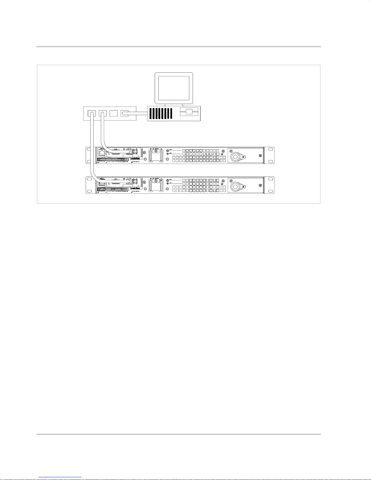
Figure 1-1 Sample configur ation using Ether net/RS-232 Interface
(1200 Watt DC Power Supplies Shown) - - - - - - - - - - - - - - - - - - - - 1–2
Figure 2-1 Power Supply Front Panel with Ethernet/RS-232 Interface Installed
(1200 Watt Power Supply Shown) - - - - - - - - - - - - - - - - - - - - - - - - 2–4
Figure 2-2 Ethernet/ RS -2 3 2 Interface Subplate - - - - - - - - - - - - - - - - - - - - - - - 2–5
Figure 2-3 Ethernet/ RS -2 3 2 Interface PCB - - - - - - - - - - - - - - - - - - - - - - - - - - 2–6
Figure 2-4 Removing the PCB- - - - - - - - - - - - - - - - - - - - - - - - - - - - - - - - - - - 2–8
Figure 2-5 RS-232 Connector Pinouts- - - - - - - - - - - - - - - - - - - - - - - - - - - - - 2–17
Figure 2-6 User Lines Signal Connector Circuit Block Diagram - - - - - - - - - - - 2–27
Figure 2-7 User Lines Cable with Ferrite Block - - - - - - - - - - - - - - - - - - - - - - 2–28
Figure 4-1 Voltage Calibration Setup - - - - - - - - - - - - - - - - - - - - - - - - - - - - - - 4–3
Figure 4-2 Current Calibration Setup - - - - - - - - - - - - - - - - - - - - - - - - - - - - - - 4–5
Figure B-1 Ethernet Bridge LEDs- - - - - - - - - - - - - - - - - - - - - - - - - - - - - - - - - B–5
TM-XR9B-01XN xiii
Page 16

xiv
Page 17

Tables
Table 2-1 Remote Programming LEDs - - - - - - - - - - - - - - - - - - - - - - - - - - - - 2–4
Table 2-2 Ethernet/RS -2 32 Int erf ace Jumper Selections - - - - - - - - - - - - - - - - - 2–7
Table 2-3 Ethernet Setup Procedure - - - - - - - - - - - - - - - - - - - - - - - - - - - - - 2–10
Table 2-4 RS-232 Setup Procedure - - - - - - - - - - - - - - - - - - - - - - - - - - - - - - 2–11
Table 2-5 Jumper positions for Ethernet or RS-232 - - - - - - - - - - - - - - - - - - - 2–12
Table 2-6 Jumper J2 Settings for Baud Rate - - - - - - - - - - - - - - - - - - - - - - - - 2–18
Table 2-7 Jumper J2 Flow Control Section- - - - - - - - - - - - - - - - - - - - - - - - - 2–19
Table 2-8 Jumper J2 Flow Control Protocol Selection - - - - - - - - - - - - - - - - - 2–19
Table 2-9 Jumper J2 Remote/Local Start-up Settings. - - - - - - - - - - - - - - - - - 2–20
Table 2-10 Remote Mode Power On Conditions- - - - - - - - - - - - - - - - - - - - - - 2–21
Table 2-11 Powe r Supply Settings - - - - - - - - - - - - - - - - - - - - - - - - - - - - - - - 2–23
Table 2-12 OVP Control Mode Selection- - - - - - - - - - - - - - - - - - - - - - - - - - - 2–24
Table 2-13 Ju mper Set tings for TTL Shutdown Circuit Logic - - - - - - - - - - - - - 2–25
Table 2-14 User Signals Connector- - - - - - - - - - - - - - - - - - - - - - - - - - - - - - - 2–26
Table 3-1 Command Parameters- - - - - - - - - - - - - - - - - - - - - - - - - - - - - - - - - 3–4
Table 3-2 Floating Point Numbers - - - - - - - - - - - - - - - - - - - - - - - - - - - - - - - 3–4
Table 3-3 Programming Commands - - - - - - - - - - - - - - - - - - - - - - - - - - - - - - 3–6
Table 3-4 Query Commands - - - - - - - - - - - - - - - - - - - - - - - - - - - - - - - - - - - 3–7
Table 3-5 Calibration Commands - - - - - - - - - - - - - - - - - - - - - - - - - - - - - - - - 3–8
Table 3-6 Status Commands - - - - - - - - - - - - - - - - - - - - - - - - - - - - - - - - - - - 3–8
Table 3-7 Command Reference - - - - - - - - - - - - - - - - - - - - - - - - - - - - - - - - - 3–9
Table 3-8 Accumulated Status, Status and Fault Registe rs - - - - - - - - - - - - - - 3–18
Table 3-9 Error Codes- - - - - - - - - - - - - - - - - - - - - - - - - - - - - - - - - - - - - - - 3–19
Table 3-10 Ethernet Mode Tips - - - - - - - - - - - - - - - - - - - - - - - - - - - - - - - - - 3–21
Table 3-11 RS-232 Mode Tips- - - - - - - - - - - - - - - - - - - - - - - - - - - - - - - - - - 3–23
Table 3-12 RS-232 a nd/or Ethernet Mode Tips- - - - - - - - - - - - - - - - - - - - - - - 3–23
Table A-1 XFR 1.2kW 7.5 V to 40 V- - - - - - - - - - - - - - - - - - - - - - - - - - - - - - A–2
Table A-2 XFR 1.2kW 60 V to 600 V - - - - - - - - - - - - - - - - - - - - - - - - - - - - - A–3
Table A-3 XFR 2.8kW 7.5 V to 40 V- - - - - - - - - - - - - - - - - - - - - - - - - - - - - - A–4
Table A-4 XFR 2.8kW 60 V to 600 V - - - - - - - - - - - - - - - - - - - - - - - - - - - - - A–5
Table B-1 Ethernet Bridge LEDs Interpretation - - - - - - - - - - - - - - - - - - - - - - - B–5
TM-XR9B-01XN xv
Page 18

xvi
Page 19

1
Description
Features
The Ethernet/RS-232 Interface is a microprocessor-controlled
option card for all models of the XFR series of DC output power
supply. Installed internally , the interface card allows you to
remotely control your power supply through your existing
network, or via a direct connection to your computer. It features
an auto-sensing 10/100Base-T network interface that provides fast
programming and readback utilizing an extensive command set.
You are able to select between Ethernet (factory default) or RS-
232 control by adjusting internal jumpe rs on the interface card.
Page 20
Features
CONTROLLER
HUB
Figure 1-1
Sample configuration using Ethernet/RS-232 Interface
(1200 Watt DC Power Supplies Shown)
Features and Functions
Interface Features
• Programmable soft limits for voltage and current
• Programmable over voltage protection with reset
• Easy-to-use, self-documenting command set
• Standardized commands for complete communic ation wit h any of th e
supplies in the system
• User-programmable isolated fault, polar ity, isolation, and auxilia ry,
user-defined output signals.
• LED status signals: error, address, remote/local operation, and over
voltage protection.
• Foldback in CV or CC mode with reset
• Software calibration
1–2 TM-XR9B-01XN
Page 21

Ethernet Features
• Auto-sensing 10/100Base-T network interface
• Robust onboard TCP/IP stack supports:
•TCP/UDP
• UDP Multicast
• Universal IP Address Assignment via:
• DHCP
•RARP
•ARP-Ping
• Easy configuration via web browser (HTTP)
• Re alPort® COM/TTY port redirection softwa re
• Status LEDs for Link, Activity, and Diagnostics
• Reset switch to reboot Ethernet Bridge
Programmable Functions
Features and Functions
• Output voltage and current
• Soft limits for volt age and current
• Over voltage protection
• Output enable/disable
• Maskable fault interrupt
• Hold and trigger
• Output relay signals
Readback Functions
• Actual voltage and current
• Voltage and current settings
• Soft voltage and current limits
• Over voltage protection setting
• Present and accumulated power supply status
• Programming error codes
• Fault codes
• Power supply model and software version identification
TM-XR9B-01XN 1–3
Page 22

1–4
Page 23

Installation and
2
Introduction
Configuration
The Ethernet/RS-232 Interface is usually installe d at the factory. Your
local distributor or service center can also install the interface,
especially for use in a previously-purchased supply already on site. You
must then configure the Interface-enhanced supply for your system
using the “Basic Setup Procedure - Ethernet” on page 2–10, or the
“Basic Setup Procedure - RS-232” on page 2–11.
To use this product, you must have the following equipment:
• a Xantrex XFR DC output power supply
• com puter-based communications software package
Page 24

Installation and Configuration
Also, depending on your specif ic configuratio n, you will ne ed additional
items.
For Ethernet (via network):
• CA T 5 network cable to connect XFR to your network
• computer connected to the network
For Ethernet (direct to computer) :
• CAT 5 crossover cable to connect XFR directly to your computer
• computer with network interface card (NIC)
For RS-232:
• null modem serial cable (cross over)
• computer with an RS-232 interface (serial/COM port)
2–2 TM-XR9B-01XN
Page 25
Initial Inspection
On first receiving your unit, perform a quick physical chec k.
• Ensure each package contains a power supply with its Ethernet/RS-
232 Interface board installed, and manuals fo r the power supply and
the Ethernet /RS-232 Interface. Any additional parts shipped with the
power supply will be identified in the supply's documenta tion.
• Inspect the unit for any signs of physical damage such as scratches,
cracks, or broken switc hes, connectors, or dis plays.
Initial Inspection
CAUTION
If you remove the unit's cover, use proper static control
techniques to avoid damage to static-sensitive com ponents on
the printed circuit board.
• Check the printed circuit board and components if you suspect
internal damage.
If the unit is damaged, save all packing materials and notify the carrier
immediately. For additional information, please see the section titles,
“Returning Power Supplies to the Manufacturer” in the manual shipped
with your complete unit.
CAUTION
Use proper static control techniques to avoid damage to staticsensitive compone nts on the printed circuit board.
TM-XR9B-01XN 2–3
Page 26
Installation and Configuration
Front Panel
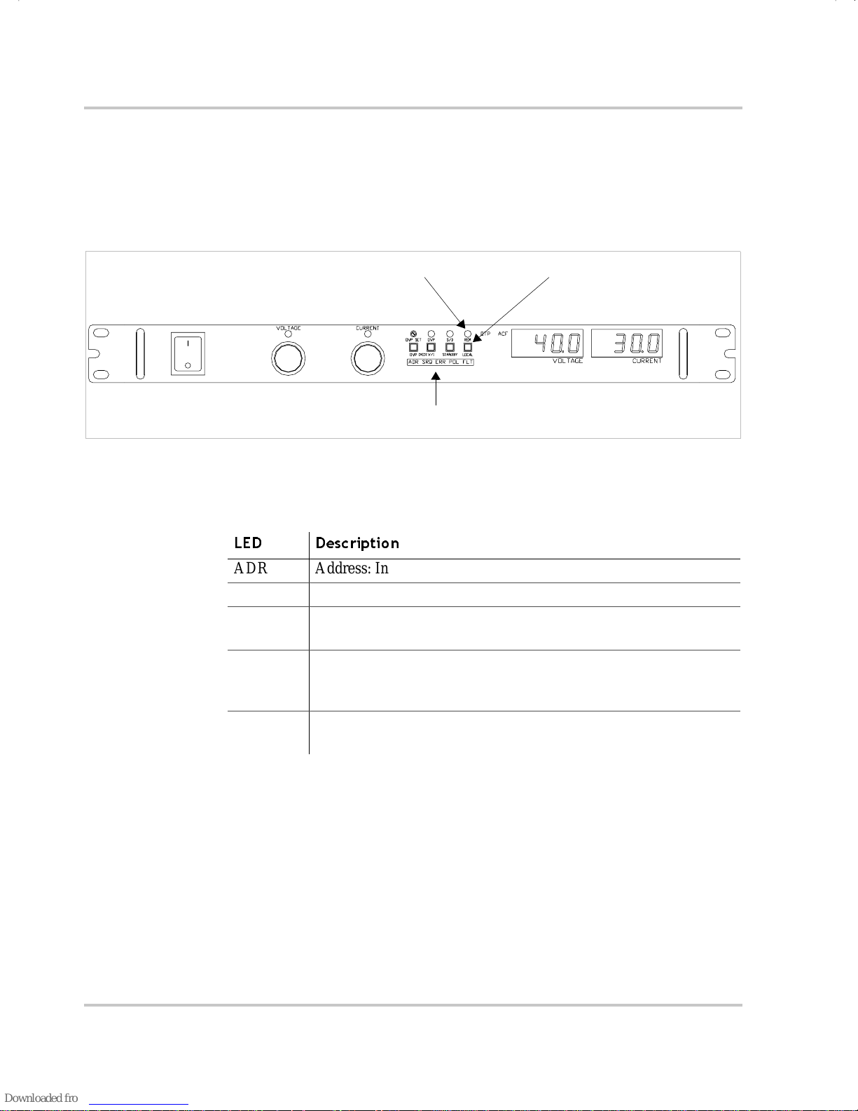
Figure 2-1 shows the front panel of an XFR 1200 Watt supply with
Ethernet/ RS -2 3 2 Interface installed. There is a further descri ption of the
Remote Programming LEDs in Table 2-1.
Remote Programming LEDs. See table.
Local Switch (LOCAL)Remote LED (REM)
Figure 2-1
Power Supply Front Panel with Ethernet/RS-232 Interface Installed
(1200 Watt Power Supply Shown)
Table 2-1
LED Description
ADR Add ress: Indicates that the master controller is addressing the unit.
SRQ Service Re quest: (GPIB only)
ERR Error: Indicates when a programming error has occurred. You can
FLT Fault: I ndicates that a fault h as o ccurred. The fault bit must be
POL Polarity: Indicates that the polarity user line has be en ac tivated.
Remote Programming LEDs
clear the ERR LED with an error query command.
unmasked. Refer to the status register in Table 3-8 on page 3–18.
Momentarily lights if PON SR Q is set to on.
See “User Lines Connector” on page 2–26.
2–4 TM-XR9B-01XN
Page 27
Ethernet/RS-232 Interface Subplate and PCB
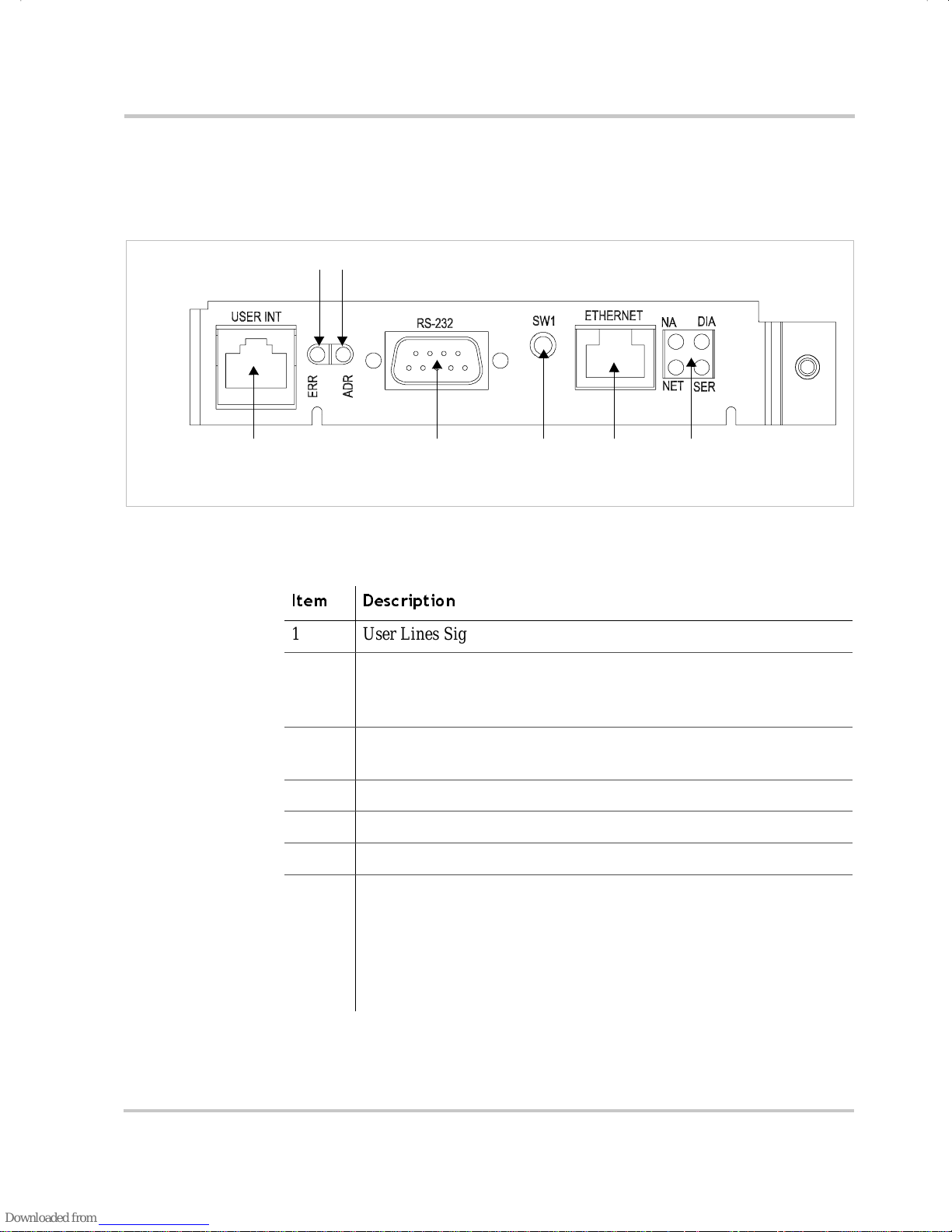
The Ethernet/RS-232 Interface Subplate is visible from the rear panel of
the unit. Rear panel componen ts are identified in Figure 2-2.
3
2
Initial Inspection
1
Note: On some models, the subplate is rotated 180 degrees.
Figure 2-2
Ethernet/RS-232 Interface Subplate
4
(XFR 1.2kW shown - located on power supply rear cover)
Item Description
1 User Lines Signal Connector
2 Error LED (ERR)
Indicates that a programming error has occurred .
Clear with error query command.
3 Address LED (ADR)
Indicates that the unit is being addressed by the master controller.
4 RS-232 Connector
5 Ethernet Bridge Reset Switch
6 RJ45 Ethernet Connector
7 Ethernet Bridge LEDs
NA: Reserved
DIA: Diagnostics
NET: Network link status
SER: Serial port activity
See page B–5.
5
6
7
TM-XR9B-01XN 2–5
Page 28

Installation and Configuration
Figure 2-3 shows the internal components on the Ethernet/RS-232
Interface PCB. Table 2-5 shows which jumpers need to be modified to
change modes or settings.
CAUTION
Use proper static control techniques to avoid damage to staticsensitive compone nts on the printed circuit board
PONREM
XON
B3
B2
FLW
B1
NA
NA
Subplate
Ethernet Bri dge
Figure 2-3
COP LEDs
CR167
CR166
J3
J4
J5
J6
123
J2
J2
Master Controll er
Master EPROM
Ethernet/RS-232 Interface PCB
J103
Slave Controller
COP LED
J64
J65
3
J93
1
CR89
1
2
Slave EPROM
1
J1
2–6 TM-XR9B-01XN
Page 29
Initial Inspection
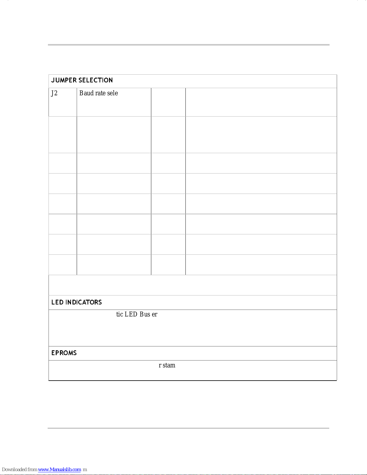
Table 2-2
JUMPER SELECTION
J2 Baud rate selection
Ethernet/RS-232 Interface Jumper Selections
page 2–18 B1 (5-6) [closed] [default]
(default 960 0)
B2 (3-4) [closed] [default]
B3 (1-2) [closed] [default]
J2 RS-232 flow control
selection hardware (RTS/
CTS) or software (X ON/
XOFF)
page 2–19 FLW (7-8) [closed] [default] Flow control disabled.
FLW (7-8) [open] Flow control enabled.
XON (9-10) [closed] [default] Hardwa re flow control.
XON (9-10) [open] Software flow control.
J2 Unused (11-12) [closed] [default] Provides extra jumper.
(13-14) [open] Not used.
J2 Power-On remote/local page 2–20 PONREM (15-16) [open] [defaul t] PON in remote.
PONREM (15-16) [closed] PON in local .
J3, J4,
J5, J6
J65 Local OVP control
J93 User TTL shutdown (S/D)
Ethernet or RS232 mode page 2–12 (2-3) [default] Et hernet.
(1-2) RS232.
page 2–24 [closed] [default]
selection
[open] Front Panel OVP Control.
page 2–25 (1-2) User TTL S /D line active low.
selection
(2-3) [default] User TTL S/D line active high.
J103 Remote OVP control
selection
page 2–24 [closed] [default]
[open]
Note: All other jumpers are not user-selectable.
LED INDICATORS
CR89 Red Diagnostic LED Bus error or Soft restart on Master circ uitry
CR166 Red Diagnostic LED Soft restart on Ma st er circuitry
CR167 Green Diagnostic LED Bus error on Master circuitry
Refer to “Troubleshooting” on page 3–20 for more informati on on the se LEDs.
EPROMS
Slave EPROM See revision number s tamped on EPROM
Master EPROM See revisi on number stamped on EPROM
TM-XR9B-01XN 2–7
Page 30
Installation and Configuration
Changing Internal Jumpers
Some of the settings on the Ethernet/RS-232 Interface card are user
selectable by way of jumpers on the printed circuit board. The proc edure
for changing the jumpers varies depending on if you have a 1.2kW XFR,
or a 2.8kW XFR.
CAUTION
If you remove the unit's cover, use proper static control
techniques to avoid damage to static-sensitive com ponents on
the printed circuit board.
Procedure for 1.2kW XFR
Ensure that the input power connection has been disconnecte d and the
unit is powe red off before you attempt to remove the top cover. Remove
all the screws holding down the top cover an d then remove the cover. The
printed circuit board that you need access to is upside down (compo nent
side down), so you must r emove all the screws tha t are holdi ng it in place .
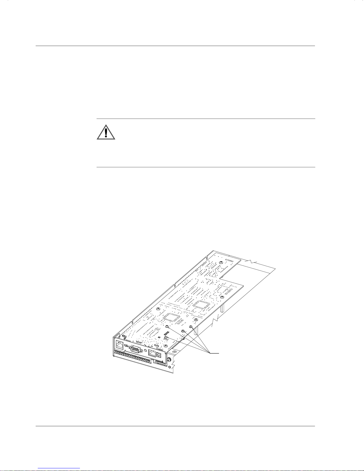
Refer to Figure 2-4 to see which screws should not be removed.
Figure 2-4
2–8 TM-XR9B-01XN
Removing the PCB
During servi ce, do no t
DURING SERVICE, PLEASE DO NOT
REMOVE THESE SCREWS
remove these scr ews
Page 31

Once that is complete, turn the board over and, if nec essary, remove the
short ribbon cab l e con nect ed to J6 4 on the interf ace card to get access to
the under side of the PCB. You can now scan the board and ref er to Figure
2-3 to locate the various components and jumpers on the PCB. Once you
have made the necessary changes, reconnect the ribbon cabl e, screw the
PCB back in place, and screw the top cover on.
Procedure for 2.8kW XFR
Ensure that the input power connection has been disconnected and
the unit is powered off before you attempt to remove the top cover.
Remove all the screws holding down the top cover and then remove
the cover. The printed circuit board that you need access to is right
side up (component side up), so refer to Figure 2-3 to locate the
various components and jumpers on the PCB. Once you have
located the jumpers and made the necessary changes, return the top
cover to its proper position, and screw it back in place.
Changing Internal Jumpers
TM-XR9B-01XN 2–9
Page 32

Installation and Configuration
Basic Setup Procedure - Ethernet
This procedure can be used as a quick refere nce for those familiar with
the configuration requirements for the Ethernet/RS-232 Interface as
installed in the DC power supply. For those who want more information,
each step refers to more detailed procedures located in subsequent
sections. Execute each step of the procedure in the sequence given.
Table 2-3
Step # D escrip ti on Action Reference
1 Mode
2 Ethernet
3 User Signal
4 Power ON Power on the unit and wait 45
5 Locate y o ur
6 Configure the
7 Test Begin Communicat ing with your
Ethernet Setup Procedure
Configure for Ethernet
Configuration
Connection
Connector
power supply on
your network
Ethernet Bridge
communications.
Connect the CAT 5 network cable to
the Etherne t connector on the
supply.
Configure and use the user line
connector signals, if required.
seconds for the Etherne t Bridge to
complete its start-up routine. Before
proceeding, c hec k to ens ure that the
green NETwork LED on the back
panel is ON.
Load the Setup Software that ships
with this interface card.
Access the device’s web server/
configuration page.
instrument.
See “Configuring for Ethernet or RS-
232” on page 2–12.
See “Ethernet Connection” on
page 2–13.
See “User Lines Connector” on
page 2–26.
See “Troub les hooting” on page 3–20
if the NETwork LED does not stay
illumin ated after startup has
completed.
See “Locating the Power Supply on
Your Network” on pa ge 2–14.
See “Configuring Ethernet Bridge”
on page 2–15.
If you do not have a TCP/IP based
software application suitable for this
application, and are familiar with RS232 type communications, see
“Installing and Using RealPort®” on
page 2–16.
2–10 TM-XR9B-01XN
Page 33

Basic Setup Procedure - RS-232
This procedure can be used as a quick refere nce for those familiar with
the configuration requirements for the Ethernet/RS-232 Interface as
installed in the DC power supply. For those who want more information,
each step refers to more detailed procedures located in subsequent
sections. Execute each step of the procedure in the sequence given.
Basic Setup Procedure - RS-232
Table 2-4
Step D escription Acti o n Reference
1 Mode
2Baud Rate
3 Flow Control
4 Remote/Local
5 RS-232
6 User Signal
7 Power ON Power on the unit. See “Additional User Opt ions and
8 Power Supply
9 Test Te st the link by communic ating with
RS-232 Setup Procedure
Configure for RS-232
Configuration
Selection
Selection
Operation
Connection
Connector
Settings
communications .
Select trans mi ssion speed.
(Default 9600)
Select flow control ON or OFF.
(Default is OFF) If flow control is
set ON, choose software-base d
XON/XOFF or hardware-based
RTS/CTS communication control.
The factory default is PON REM. See “Remote/Local Operation” on
Connect the RS-232 cable assembly
to the RS232 connec tor on the
supply.
Configure and use th e us er line
connec to r signals, if required.
Configure the controller’s operating
parameters to ma tch the power
supply settings.
the power supply.
See “Configuring for Ethernet or RS-
232” on page 2–12.
See “Baud Rate Se lection” on
page 2–18.
See “Flow Control Selection” on
page 2–19.
page 2–20.
See “Power Supply Settings” on
page 2–23
See “User Lines Connector” on
page 2–26.
Settings ” on page 2–24 and “User
Signals” on page 2–26 for
information abou t Local/Remote
OVP, TTL Shutdown, and auxiliary
connec to r user signals.
See “Power Supply Settings” on
page 2–23.
Example: VSET2;ISET1
This comm an d stri ng s ets pow er
supply voltage to 2V and its current
limit to 1A.
See “Operation”.
TM-XR9B-01XN 2–11
Page 34

Installation and Configuration
Configuring for Ethernet or RS-232
This interface card can be configured for Ethernet communication, or for
RS-232 communication, but not both simultaneously. From the factory,
the instrument will be configured f or Ethernet communication. Therefore
you should only need to follow these instructions if you are switching
over to RS-232, or back to Ethernet. To switch between the two
configurations, you must change internal jumpers on the interface card.
See “Changing Internal Jumpers” on page 2–8. Also refer to Table 2-2
and Figure 2-3 on page 2–6 to locate the corre sponding jumpers.
Table 2-5
Jumper RS-232 Ethernet
J3 1-2 2-3
J4 1-2 2-3
J5 1-2 2-3
J6 1-2 2-3
Jumper positions for Ethernet or RS-232
When you have finished changing the jumper positions, ensure that the
baud rate, flow control, and power-on state are configured properly for
your new setup. These setti ngs are also changed by adding or removing
jumpers, so it is best to perfor m this adjustment, if necessar y, while the
interface card is accessible. Refer to “Baud Rate Selec tion” on page 2–18,
“Flow Control Selection” on page 2–19 and “Remote/Local Mode
Start up” on page 2–20 for more detailed information on how to
reconfigure these settings.
Note: If you are switching the inte rface card back to Ethernet it is
recommended to set the baud rate to 9600, turn flow control off, and
have the unit power-on in remote mode (these are the default settings).
2–12 TM-XR9B-01XN
Page 35

Ethernet Communications
Ethernet Connection
There are two options for controlling your XFR power supply via
Ethernet - "Connect ing to a Network" or "Connecting Dire ctly to your
Computer." The first option is to connect the power supply to a network,
and control the unit from your computer which is also connected to the
network. The second option is to con nect the XFR directly to your
computer's networ k interface card (NIC). This bypa sses the need for an
existing networ k.
Connecting to a Network
All that is requir ed to conn ect your XFR to a net work is a straig ht thr ough
CAT 5 network cable and an available network port.
Connecting Directly to your Computer
Ethernet Communications
To connect your XFR dire ctly to your com puter you will need a crossover CAT 5 network cable. You will also need to check your network
settings on your computer to ensure that you are using a static IP addr ess.
Check with your IT department for assistance.
TM-XR9B-01XN 2–13
Page 36

Installation and Configuration
Locating the Power Supply on Your Network
1. Record the MAC address for your power supply. This will be visible
at the back of the XFR, on the interface card subplate. For example,
MAC Address
00429D 22EF45
MAC Address:
______________________________
2. Insert the Xantrex XFR Ethernet Software Utilities CD into your CD
drive.
3. If the CD does not start automatica lly, double-clic k the My Computer
icon, double-cl ick the CD icon and then double-click
autorun_main.htm.
4. When the menu appears, click Xantrex Device Dis covery to in stal l
and run the application. This application will find and list a ll XFR’s
with an Ethernet/RS-232 Interface card on your network.
5. You can now scan the list and locate your new XFR by its MAC
address.
6. If your network uses a DHCP server and DHCP was enabled on the
XFR, your new inst rument wi ll already ha ve an IP a ddress. If not, y ou
will have to configure an IP address manually. Refer to steps 2 and 3
in “Configuri ng Ethernet Bridge” on page 2–15 for more information.
7. Write down the IP address so that you can acc ess the instrument via
its web server, and for when you start communicating with the power
supply.
2–14 TM-XR9B-01XN
Page 37

Configuring Ethernet Bridge
The Ethernet/RS-232 Interface card has an Ethernet Bridge that converts
the ethernet packets to ser ial data signals for processing by t he embedded
microcontroller. The Ethernet Bridge m ust be properly configured for
serial communications with the microcontroller. For example, settings on
the Bridge, such as Baud Rate and Flow Control, must match the jumper
settings on the interface board.
There are two ways to gain access to the configuration menu for the
Ethernet Bridge. One is to run the Setup program that is available on the
Software CD. This program will find your instrument and allow you to
configure it by clic king on th e i nstrument ’s IP address. You will then need
to enter the correct username and password to be able to configure the
device.
Default Usernam e: root
Default Password: dbps
The other method is to open up a web browser like Internet Explorer, and
type in the IP address for the i nstrument. Again, you will be asked for the
username and password. Once you have accessed the configuration page,
follow these steps for proper setup.
Ethernet Communications
1. Click Configuration > Seri al Port, and ensure that the following
settings have been selected:
• Ba ud Rate: 9600
• Data Bits: 8
• Pa rity: None
• Stop Bits: 1
• Flow Control: None
Click Apply onc e you have finished adjusting the above settings.
2. Now click Configuration > Network. If your network uses a DHCP
server (ask your IT department) you should select Obtain IP address
automaticall y using DHCP and then click Apply. If your network
doesn’t use a DHCP s erv e r, select Use the following IP addr ess: and
enter an appropriate IP address, Subnet Mask and Default Gateway. .
3. Ask for assistance from your IT department to obtain a n appropriate
IP address, Subnet Mask, Default Gateway, Name Server, and
Domain. Once you have made the a ppropria te ch anges, clic k Apply. If
this changed the setting, the device will reboot, so you will have to
renew your c onnection to its configuration webpage for any further
configuration changes.
TM-XR9B-01XN 2–15
Page 38

Installation and Configuration
Installing and Using RealPort®
Background
RealPort® software al lows you to keep using your existing appli cations
that rely on COM ports and RS-232 links for communication purposes,
instead of ha vi ng to de velop TCP/IP based network appl ications. Inst al led
on a network-enabled PC, RealPor t® cre ates a virtual COM port. As
such, your applic ation stil l thinks it is wor king with a real s erial por t, suc h
as COM1. When the application sends data to this serial port, RealPort®
ships the data across the network to the Ethernet Bridge in your power
supply. By doing this, the network is transparent to your exi sting
application.
Installation
RealPort® can be installed on any P C running Windows NT 4.0,
Windows 2000, or Windows XP.
1. Insert the Xantrex XFR Ethernet Software Utilities CD into your CD
drive
2. If the CD does not start automatica lly, double-clic k the My Computer
icon, double-cl ick the CD icon and then double-click
autorun_main.htm.
1
3. When the menu appears, click Digi RealPort®.
4. Follow the on-scr een instructions for proper installation.
Note: RealPort® driver s for UNIX systems are availa ble. Contact your
Xantrex repre sentative to obtain these drivers if necessary.
Using RealPort®
Once you have installed the RealPort® driver for your power supply,
using it is as simple as running your existing applicati on (such as
HyperTerminal, or a custom RS-232 application) and setting the COM
port to be the one created by the RealPort® driver for your instrument.
1.RealPort® is a registered trademark of Digi Inter national.
2–16 TM-XR9B-01XN
Page 39

RS-232 Communications
RS-232 Connection
WARNING
Do not operate the power supply and the computer at
significantly different frame potentials. The interf ace
connection syste m may not be capabl e of handling t he resul ting
excessive ground currents.
Use an approved RS-232 connector and null modem cable when
connecting the Ethernet/RS-232 Interface to your computer. The RS-232
connector uses the 9 pin mating connector on the rear panel. Figure 2-5
shows the pinouts for the RS-232 connector.
Refer to Figure 2-2 on pa ge 2–5 for the position of the RS-232 connector
on the rear panel subplate.
RS-232 Communications
6 NC
7 RTS
8 CTS
9 NC
Figure 2-5 RS-232 Connector Pinouts
1 NC
2 RXD
3 TXD
4 NC
5 GND
TM-XR9B-01XN 2–17
Page 40

Installation and Configuration
Baud Rate Selection
Serial transm ission sends and rec eives data in bit streams at fixed bit
rates. Both the computer and the interface must have the same bit rate
setting for proper communication. The default baud rate is 9600. We
recommend that you do not change this setting. If the setting must be
changed, use Table 2-6 to select the correct jumper positions. You will
need to remove the cover to change any jumpers. See “Changing Intern al
Jumpers” on page 2–8.
Table 2-6
Baud Rate B3 B2 B1
9600 closed closed closed
4800 open closed closed
2400 closed open closed
1200 open open closed
600 closed closed open
300 open closed open
150 closed open open
75 open open open
Jumper J2 Settings for Baud Rate
2–18 TM-XR9B-01XN
Page 41

Flow Control Selection
Flow control signals regulate data flow for proper communication. To
enable or disable the flow control, change the J2 FLW jumper according
to Table 2-7. With flow control enable d, you can use either software or
hardwa re pro tocol s to con trol flow rat e s. You will need to remove the
cover to change any jumpers. See “Chan ging Internal Jumpers” on
page 2–8.
RS-232 Communications
Table 2-7
J2 FLW Jumper Setting C on dit io n
closed (default) Disable Flow Control
open Enable Flow Control
Jumper J2 Flow Control Section
Once flow control is enabled, two flow control methods are available.
You can select software based XON/XOFF flow protoco l or hardware
based RTS/CTS by changing an inte rnal j umper. T able 2-8 shows the flow
control condit ions with r egards to the J2 XON jumper.
Table 2-8
J2 XON Jumper Setting Condition
closed (default) Hardware Flow Control
open Software Flow Control
Jumper J2 Flow Control Protocol Selection
(RTS/CTS protoc ol)
(XON/XOFF protocol)
TM-XR9B-01XN 2–19
Page 42

Installation and Configuration
Remote/Local Operation
Remote/Local Mode Startup
The power supply can be set to start-up in remote or local mode. To
change this setting, the PON REM jumper must be adjusted according to
Table 2-9. You will need to remove the cover to change any jumpers. See
“Changing Inte rnal Jumpers” on page 2–8 for informa tio n on how t o
change internal jumper settings.
See Table 2-9 for the switch settings.
Table 2-9
J2 PON REM Jum per Sett in g Power ON result s
open (default) Unit in remote mode
closed Unit in local mode
With the PON REM jumper open, the power supply will start up in
remote mode. The green REM LED on the front panel will be lit,
signaling t hat the powe r supply i s under the contr ol of th e digita l i nterface
card. The output of the power sup ply is activ e on sta rtup. To promote load
safety, power ON defaults are zero for the output voltage and curr ent
limit, and 110% of maximum output voltage for the OVP trip point. See
T abl e 2-10. Refer to “Operation” for more inf ormation about the inte rfac e
commands listed in the table.
If the PON REM jumper is closed, the power supply will power up in
local mode. Power supply control is at the front panel. During an
operating session, you can toggle between local mode and remote mode
by using the front panel LOCAL button or sending commands as
described in Table 2-10.
Jumper J2 Remote/Local Start-up Settings.
Note: The default setting for thi s jum per is open. If you require it to be close d
(PON in local mode) you can obtain a spare jumper by rem oving the one that
connects pins 11 and 12 on J2 as these pins are unused.
2–20 TM-XR9B-01XN
Page 43

Remote/Local Operation
Table 2-10
Condition Default Settings 7.5-140 Model Example
Voltage 0 V VSET 0
Current 0 A ISET 0
Soft Voltage Limit VMAX (see models) VMAX 7.5
Soft Current Limit IMAX (see models) IMAX 140
OVP Trip Voltage Model VMAX + 10% OVSET 8.25
Delay 0.5 s DLY 0.5S
Remote Enable ON REN ON
Foldback Protection OFF FOLD OFF
Output ON OUT ON
Hold OFF HOLD OFF
Unmask NONE UNMASK NONE
AUXA OFF AUXA OFF
AUXB OFF AUXB OFF
Remote Mode Operation
While in remote mode, use the interfa ce commands to control the output
of the power supply from a computer . See “Operation” for a complete list
of device-dependent commands available with thi s interface.
Remote Mode Power On Conditions
From remote mode, change to local mode operation by pressing the front
panel LOCAL button or by sending either the GTL command or the
REN OFF command. You can disable the LOCAL button by using the
LLO command. For an examp le of how to use Loca l Lockout, see “Local
Lockout (LLO) Command” on page 2–23.
T o return to re mote mode, en sure th at the REN command is s et to ON and
then send any valid device-dependent command. Since the remote mode
output se ttings m ay be di f ferent f rom the loca l mode se tt ings, t he output i s
programmed to prote ct the load by turni ng of f when you tog gle f rom local
to remote m ode during a session. Check your remote settings and then
send OUT ON to restore the output.
TM-XR9B-01XN 2–21
Page 44

Installation and Configuration
Local Mode Operation
In local mode operation, you set the voltage and current output levels and
the OVP trip level with controls located on the front panel. Refer to the
operating manual for a description of the functions available at the front
panel.
While in local mode operation, you can change power supply control to
remote mode by ensuring that REN is ON, then sending any software
command and OUT ON to restor e the output. Return to local mode by
pressing the front pan el LOCAL button, u nless Loc al Loc kout is in e ff ect.
If LLO is in effect, use the GTL command to send the power supply into
local mode, or use the REN OFF command to turn of f LLO and retur n the
power supply to local mode.
Example:
Press the LOCAL button Set unit to local mode
Id? Put the unit into remote mode
(Use any command to do this.)
Press the LOCAL button
Remote Enable (REN) Command
You can use the Remote Enable command to toggle between local mode
and remote mode . The default setting at startup is REN ON. With the
remote enable command set at REN ON, you can return the power suppl y
to remote mode whenever you send any command from the computer.
Any time that you change from loc al to remote mode during a se ssio n, the
output is programmed to turn off, since the remote mode settings may be
diffe rent f rom the local mode settings. Send the OUT ON command to
restore the output.
You can turn off Remote Enable and move power supply control to the
front panel by sending the REN OFF command. If the Local Lockout
condition is in effect, sending the REN OFF command will turn off the
LLO condition before sending the unit into local mode.
To check whether the power supply is remote enabled, use the REN?
query command.
Example:
REN ON Enable the power supply to be sent into
Retu r n to loc a l m o d e .
remote mode
VSET 10;ISET 2 Put the unit into remote operation mode
2–22 TM-XR9B-01XN
(Use any command to do this.)
Page 45

Local Lockout (LLO) Command
Use the Local Lockout command to disable the LOCAL button on the
power supply front panel. With LLO in effect, you cannot return to local
control by pressing the front panel LOCAL switch. You can still return to
local mode by sending the Go to Local (G TL) command. However , to turn
off LLO a nd return the power supply to local mode, send the REN OFF
command. Only the REN OFF command will remove the LLO condition.
Example:
LLO Set Local Lockout
GTL Return the power supply to local mode.
REN OFF Tur n off Local Lockout and return the
Power Supply Settings
Power Supply Settings
Local Lockout is still in effect
power supply to local mode
For serial communication, the computer and the Ethernet/RS-232
Interface must share the same communicati on se ttings. M ake sure tha t the
settings of the compute r and of the power supply agree with those shown
in Table 2-11.
Table 2-11
Parameter Setting
Transmission Asynchronous
Mode Full Duplex
Speeds 75, 150, 300, 600, 1200, 2400, 4800, 9600 (default)
Parity None
Connector DB9-pin Male
Start Bit 1
Stop Bit 1
Data Bits 8
Protocols XON/XOFF
Power Supply Settings
RTS/CTS
NONE (default)
TM-XR9B-01XN 2–23
Page 46

Installation and Configuration
Additional User Options and Settings
You can customiz e remote operation settings for OVP (over voltage
protection) control and TTL shutdown by changing jumper posit ions on
the Ethernet /RS-232 Interface card. Ref er to the operating manual for
information on how to use over voltage protection and TTL shutdown.
OVP Selection
Over voltage protection (OVP) on the Ethernet/R S-232 In terface is set at
the factory for remote software operation. When operating the power
supply in remote mode, you control the OVP trip level using the OVSET
software command. If you return the power supply to local operation by
using the REN software com mand or the front pane l LOCAL switch,
control of the OVP trip level changes from sof tware control to the front
panel OVP potentiometer . The default OVP trip level is set as 110% of the
power supply's rat ed output voltage. See Table 2-10 on page 2–21 for a
complete list of remote power ON defaul t settings.
You can isolate the location of OVP control by changing the positions of
the Local OVP Control jumper J65 and the Remote OVP Control jumper
J103, both on the Ethernet/RS-232 Interface PCB. The default jumper
settings allow control of OVP to depend on the operating state of the
power supply. By physically changi ng the jumper se ttings, you can i solate
the location of OVP c ontrol to so ftware co ntrol on ly or f ront panel control
only. Table 2-12, “OVP Control Mode Selection” on page 2–24 shows a
table of jumper settings and OVP programmin g selection. Refer to Figure
2-3 on page 2–6 for the location of the jumpers on the Ethernet/RS-232
Interface PCB. You will ne ed to remove the cover to change any jumpers.
See “Changing Internal Jumpers” on page 2–8.
Table 2-12
PCB Jumper
J65 Position
Closed (defaul t) Closed (default) Software or Front Panel OVP control
Closed Open Software OVP control only
Open Closed Front Panel OVP control only
Open Open Front Panel OVP control only
2–24 TM-XR9B-01XN
OVP Control Mode Selection
PCB Jump er
J103 Position OV P Programm in g Selecti on
(dependent on the power supply operating
state)
Page 47

TTL Shutdown Polarity
You can use the Shutdown function to disable or enabl e the supply's
output. Disa bling the supply using TTL shutdown allows you to make
adjustments to the load or to the power supply without shutting down the
power supply. With the Ethernet/RS-232 Interface installed, TTL
shutdown is a ctivated by a TTL signal to Pin 1 of the user lines connector
on the interface subplate. The shutdown user line uses a 0-5Vdc TTL
input with a high signal range of 2.2-5.0Vdc. The current range of the
shutdown line is 1-10mA. See Figure 2-6, “User Lines Signal Connector
Circuit Block Diagram” on page 2–27 for a schematic of the user lines
connector containing the shutdown user line.
You can select the logic level of the TTL input by changing the J93
connector on the Ethernet/RS-232 Interface PCB. Table 2-13 shows the
TTL signal levels for the J93 jumper settings. See Figure 2-3 for the
location of the J93 jumper on the printed circuit board. You will need to
remove the cover to change any jumpers. See “Changing Internal
Jumpers” on page 2–8.
Additional User Options and Settings
Table 2-13
PCB Jumper J93 Position TTL Signal Level Supply Output Condition
Pin 2 to Pin 3 (default) HIGH
Pin 1 to Pin 2 HIGH
Jumper Settings for TTL Shutdown Circuit Logic
OFF
LOW
LOW
ON
ON
OFF
TM-XR9B-01XN 2–25
Page 48

Installation and Configuration
User Signals
User Lines Connector
Auxiliary User Lines c onnect or , loc ated on th e Ethernet/R S-232 Inter face
rear panel, provide s several signals to increase your operating control of
the supply. These signals are dependent on the operator's design and uses.
The operation of the user lines connector signal requires that you pr ovide
external Vcc and ground. Use a standa rd 8-position telephone jack and
data cable to connect to the user lines connector. To locate the connector,
refer to the Ethernet/RS-232 Interface subplate drawing in Figure 2-2 on
page 2–5. See Ta ble 2-14 for pin descript ions. The user lines connector
outputs can sink a current of 5mA each. Figure 2-6 on page 2–27 shows
the portion of the option board schematic which contains the user line
connector. Use the schematic as a reference when making input or output
connections.
Table 2-14
Pin Function
1 External TTL s hutdown input signa l (See “TTL Shutdown
2 Polarity signal, open collector (asserted by VSET -x)
3 Isolation s ignal, open collector (asserted by OUT OFF)
4 Fault signal, open collector (asserte d wh en bit set in fa ult regist er )
5 External Vcc, 15V maximum (suppli ed by connecting an d
6 External ground and shutdown return (supp lied by connecti ng and
7 Open collector user signal (asserte d by AUXA ON)
8 Open collector user signal (asserte d by AUXB ON)
User Signals Connector
Polarity” on page 2–25)
operating an external source)
operating an external source)
User Line
Note: On some models, the
connector is rotated 180°.
2–26 TM-XR9B-01XN
Page 49

User Signals
Figure 2-6
User Lines Signal Connector Circuit Block Diagram
TM-XR9B-01XN 2–27
Page 50

Installation and Configuration
User Lines Cable Connection
Use a standard 8-position telephone jack and data cable to connect to the
user line connector. Add a ferrite block to reduce radiated emission. The
one inch squa re ferrite block with built-in housing c lip is packaged and
shipped with the power supply interface card.
To install the ferrite block:
1. Position the bloc k no more than 5 c m (2 in.) from the power supply
end of the user line connector cable.
2. Open the ferrite block housing.
3. Loop the cable through the ferrite block. See Figure 2-7, “User Line s
Cable with Ferrite Block” on page 2–28.
4. Close the housing clip.
The ferrite block ensures tha t the pow er s up ply syst em meet s rad i ated
emission requirement 89/336/EEC for CE mark approval. See the power
supply's operating manual for noise specifications.
Figure 2-7
User Lines Cable
Ferrite Block
To User Cu s to m In te r fa c eTo Connector
on XF R
User Lines Cable with Ferrite Block
2–28 TM-XR9B-01XN
Page 51

3
Introduction
Operation
This section covers Ethern et/R S- 2 3 2 Interface programming, including
an extensive set of device-dependent commands, error codes, and status
and fault register information.
Page 52

Operation
RS-232 Operation
When the Ethernet/RS-232 Interface card is configured for RS-232 you
can send and receive data between your powe r supply and computer,
relying on bit serial communication. You can use the computer cont roller
to issue commands to the power supply for programming, queries,
calibration, or status. The power supply responds to the complete
command set of device dependent software commands shown in
“Command Reference” on page 3–9.
Ethernet Operation
When the card is confi gu re d for Ethernet, you can send and receive data
between you power supply and computer via your network. The same
command set is used for RS-232 and Ethernet. The only difference is
medium and protocol used.
Command Syntax
Manual Conventions
The manual use s these conventions when displaying command
information. These charact ers are not pa rt of the command but are used to
denote parameters used with the command.
< > (angle brackets) Angle brackets encl ose a parameter. Do not include
/ (slash) Separates two alternative parameters. W hen a slash
the angle brackets in the command li ne you send to
the computer.
separates two para me ters, you can use either
parameter to achieve the same result.
Example:
Entering
<1/ON>
1 or ON will achieve the sam e result.
3–2 TM-XR9B-01XN
Page 53

Command Format and Parameters
The device-dependent language for the Ethernet/RS-232 Interfa ce
consists of commands and parameters. A command is a one word code
which either gives instructions to the interface or asks for information
from the interface. A command may be followed by one or more
parameters, a short c ode that changes the stat e of the power supply or the
state of the bit register. Table 3-1, “Command Parameters” on page 3–4
lists the parameters that affect the command set.
Format:
COMMAND or
COMMAND <parameter> or
COMMAND <parameter>,<parameter>
• You can enter commands in upper or lower case lettering.
Example: MASK FOLD = mask fold
• Do not further abbreviate command names or parameters.
Example: MASK FOLD ≠ MK FOLD
Command Syntax
MASK FOLD ≠ MASK FD
• Use a space between the command and the first paramet er. Any
number of consecutive spaces is treated as one space. Numeric data
may contain leading spaces. Embedded spaces between digits or
between a digit and a decimal point are not accepted.
Example: MASK FOLD = MASK FOLD
VOUT 3.4 = VOUT 3.4
VOUT 3.4 ≠ VOUT 3. 4
• Use commas between parameters in those commands with more than
one parameter, and between mne monic parameters as in the MASK
and UNMASK commands. Only one comma is all owed and i t may be
preceded or followed by any number of spaces.
Example: M A SK C V, OV, FOL D
TM-XR9B-01XN 3–3
Page 54

Operation
Table 3-1
Parameter Description Form
<current>, <Ihi>, <Ilo> The current in amps or milliamps . If no unit is given,
<time> The time in seconds or mill ise cond s. If no unit is given,
<voltage>, <Vlo>,
<Vhi>
<mnemonics> A combina t ion of CV, CC, CV, OV, OT, SD, FOLD,
<state> The state of a binary condition. <1/ON, 0/OFF>
Command Parameters
the default unit is amps.
the default unit is seconds.
The voltage in vol ts or mil livolts. If no unit is given,
the default unit is volts.
ERR, PON, REM, ACF, OPF, and SNSP. See MASK
and UNMASK commands in the command reference
for use of the ALL and NONE parameters.
<float>
<float>A
<float>mA
<float>
<float>s
<float>ms
<float>
<float>V
<float>mV
See registers on
page 3–17.
Floating Point Number <float>
Variables sent with command parameters are floating point numbers.
Table 3-2 defines the structure of floatin g point numbers for use with the
software comma nds.
Table 3-2
Floating Number Definition Example
The floating point number has four significant figures.
It can be of either sign, positive or negat ive.
A floating point num ber can have one decimal point. 0.123
Scientific Notation
Use E or e after the number for a base ten expo nent.
An integer of either sign must follow an exponent.
Floating Point Numbers
1.234
-1.234
+1.234
1.2
123.4
123.0E-1
1.2E-1
10.00E+1
3–4 TM-XR9B-01XN
Page 55

Command Strings
If you send more than one command line, separate the commands with a
semicolon. The semicolon may be prece ded or followed by spaces.
Example:
ISET 2.0A; VSET 5V
ISET 2.0A; VSET 5V
Command Terminators
Terminators indicate the end of a command string and tell the power
supply to execute the command. The ter mination character is CR
(Carriage Return).
Format:
COMMAND <parameter >; COMMAND <parameter>,
<parameter><CR>
Command Syntax
Order
You may send commands in any order, keeping in mind that only those
commands received after a HOLD and before a TRG (trigge r) will be
released by the TRG command. In addition, only these commands
received after a supply disable (OVP or foldback protection) and before a
RST (reset) or OUT ON command will be released by the RST command
or the OUT command. Commands are executed in the order they are
received.
TM-XR9B-01XN 3–5
Page 56

Operation
Command Summary
Use these com mands to control the operation of the supply. They are
listed here in order of function such as PROGRAMMING, QUERY,
CALIBRATION, and STATUS commands. See “Command Reference”
on page 3–9 for more detailed information about each command and its
use.
Table 3-3
Command Description
AUXA Selects the state of the AUXA output signal on the Pin 7 of the
AUXB Selects the state of the AUXB output signal on the Pin 8 of the
CLR Initializes the power supply to its Power ON (PON) state.
DLY Sets a programmable time delay which is executed by the supply
GTL Sends the supply to local mode.
FOLD Sets foldback mode for the supply.
HOLD Enables or disables voltage/current setting hold mode for the
IMAX Sets an upper soft limit on th e progra mmed output current for the
ISET Sets the output current of the supply in amps (default) or in
LLO Local Lockout. Disables the front panel LOCAL button.
OUT Enables or disabl es voltage/current output for the supply.
OVSET Sets the over voltage protection trip point for the supply in volts
REN Sets remote mode or loc al mode.
RST Resets the supply to the present voltage and current settings if the
TRG Implements programmed voltage and current settings which had
VMAX Sets an upper soft limit on the supply’s programmed output
VSET Sets the out put voltage of the power supply in volts (defau lt) or in
Programming Commands
user lines connector.
user lines connector.
before reporting fa ult conditions after a new output voltage or
current is sp ecified .
supply.
supply.
milliamps.
(default) or in millivolts.
output is disa bled by OVP or foldback protection.
been in hold mode.
voltage.
millivolts.
3–6 TM-XR9B-01XN
Page 57

Command Summary
Table 3-4
Query Commands
Command Description
AUXA? Asks for the state of the set value for the AUXA command
AUXB? Asks for the state of the set value for the AUXB command
CMODE? Asks for the power supply’ s c alibration mode status.
DLY? Asks for the programmable time de lay setting be fore the supply
reports fault conditions.
ERR? Asks for the most recent remote program ming error which
occurred in the supply since the la st time the error query
command (ERR?) was us ed.
FOLD? Asks for the s upply’s present foldback setting.
HOLD? Asks for the present hold mode setting.
ID? Asks for the power supply’s model name and master EPROM
version.
IMAX? Asks for the supply’s soft current limit setting.
IOUT? Measures the supply’s actual current output.
ISET? Asks for the supply’s present output current limit setting.
OUT? Asks for the present enabled/ disabled status of the supply’s
output.
OVSET? Asks for the supply’s present over voltage protection limit.
REN? Asks for th e state of remote enable.
ROM? Asks for the version number of the master and slave EPROMs on
the in te r f ace PCB.
VMAX? Asks for the supply’s soft voltag e limit setting.
VOUT? Me asures the supply’s actual voltage output.
VSET? Asks for the suppl y’s present output vol tage setting.
TM-XR9B-01XN 3–7
Page 58

Operation
Table 3-5
Command Description
CMODE Places the su pply into calibration mode.
IDATA Calculates the slope and interc ept for current programming.
IHI Sets the current output to the high calibration point.
ILO Sets the current output to the low ca libration point.
IRDAT Calculates the slope and intercep t for curr ent readback.
IRHI Sets the current output to the high re adba ck point.
IRLO Sets the current output to the low readback point.
OVCAL Calibrates the over voltage protection (OVP).
VDATA Calculates the slope and intercept for volt age programming.
VHI Sets the voltage output to the high calibration point.
VLO Sets the voltage outp u t to the low calibration point.
VRDAT Calculates the slope and intercep t for voltage readback.
VRHI Sets the voltage output to th e high readback point.
VRLO Sets the voltage output to the low readback point.
Table 3-6
Calibration Commands
Status Commands
Command Description
ASTS? Asks for the supply’ s accumulate d st atus register.
FAULT? Asks for the supply’s fault register for the status preset operating
conditions.
MASK Prevents the supply's previ ously unmasked operating conditions
from setting bits in the fault register.
STS? Asks for the supply’ s present status register.
UNMASK Enabl es you to select th ose supply 's operating conditi ons that y ou
are most interest ed in monitoring for fault occurrence.
UNMASK? Asks for the supply's fault conditions which are currently enabled
(unmasked).
3–8 TM-XR9B-01XN
Page 59

Command Reference
Command Reference
Table 3-7
Command Descrip tion
ASTS? Asks for the supply’s accumulated st atus register. The accumulated status regi s ter
AUXA <1/ON>,
<0/OFF>
AUXA? Asks for the present set value of the AUXA output s ignal.
AUXB <1/ON>,
<0/OFF>
AUXB? Asks for the present set val ue of the AUXB output signal.
Command Reference
stor es an y bi t th a t w as en t er e d in th e st at u s re gi st er sin ce the accu mu lated status
query command (ASTS?) was last used , reg ardless of whether the cond ition still
exists. The accumulated status register has the same bits, weights, and conditions
as the st atus register. A bit in the accu mulated status register will be set at 1 if the
corresponding bit in the stat us register has been 1 (TRUE) at any time si nce the
register was last read. See “Accumulated Sta tus, Status, and Fault Registers” on
page 3–17. The ASTS? q u ery clears th e status register.
Response: ASTS <statu s mas k> where st at us mask is the deci mal equ ivale nt of the
total bit weights for the operating co nditions as listed in the status register.
Controls the AUXA output s ignal level at rear panel connector Pin 7. Active low.
Initial va lue: AUXA 0
Response: AUXA 0 (OFF) or AUXA 1 (ON)
Controls the AUXB output signal level at rear panel connector Pin 8. Active low.
Initial va lue: AUXB 0
Response: AUXB 0 (OFF) or AUXB 1 (ON)
CLR Initializes the power supply to its power ON condition. If is s ued while in local
mode, CLR will force power supp ly settings to register default values as in but
these defa ult sett ing s will not c ome i nto ef fect unti l t he p ower supp ly i s switc hed to
remote mode operation. The CLR commands will clear faul ts from the fault
register. CLR will not reset CMODE.
CMODE <1/ON>,
<0/OFF>
CMODE? Asks for the power supply’s calibration mode status.
TM-XR9B-01XN 3–9
CMODE ON places the power supply into calibration mode for processing
calibration commands.
Initial va lue: CMODE OFF or CMODE 0
Res p on s e: CM O D E 0 ( disab led)
CMODE 1 (enabled)
Page 60

Operation
Table 3-7
Command Descrip tion
Command Reference
DLY <seconds> Sets a programmable ti me delay employed by the su pply before reporting fault
conditions. The power supply uses the time delay after receiving a new output
voltage or curre nt setting via VSET or ISET, or after receiving RST, TRG, or OUT
ON commands. During the time delay, the power supply disables CV, CC, and
FOLD conditions from generating faults, preventing pos sible nuisance foldback if
the supply momenta rily switches modes while changing an out put setting.
Range: 0 to 32 seconds, with 32ms resolution
Initial value: 0.5 second
DLY? Asks for the setting of the programmable time delay before the suppl y reports fault
conditions.
Response: DLY <seconds>
ERR? Asks for the most recent remote programming error. When the power supply
detects a program ming error, it lights the ERR LED and sets the ERR bit in the
accumulated sta tus and fault registers . If the error bit has been masked using the
MASK command, then the ERR bit in th e r egisters will not set. Once an error is
detected, the re maining portion of the command line is discarded. An error query
clears the ERR bit in the accumulated status register. See “Error Codes” on page 3–
19.
Response: ERR <error number> Example: ERR 0 (if no error)
FAULT? Asks for the sta te of the fault register. A bit is set in the faul t r egister when a fault
arises for that condition. Lists the conditions whi ch activate a fault bit. You can use
the MASK command to disable bits from being set in the fault register.
When a bit is set in the faul t register it also assert s a si gnal on the Pin 4 user signal
line. You can tie the Pin 4 fault line signal to the power supply's own External
Shutdown user line, Pin 1, so that the shutdown signal goes low (active) in the case
of a user-defined fault.
The FAULT? query clears bits in the supply's fault register and fault line .
Response: FAULT <fault mask> where fault mask is the decimal equivalent of the
total bit weights for the operating co nditions as listed in the fault regist er. See
“Accumulated Status, Status, and Fault Registers” on page 3–17.
FOLD
<2/CC>, < 1/CV> ,
<0/OFF>
Sets foldback mode for the supply. Foldback protection disables the power supply
output when the output enters the fold condition. Reset with the RST command.
Example: Specify FOLD 1 or FOLD CV (Constant V oltage) when you want the
supply to operate in Cons tant Current mode and have foldback protection disable
the output if the supply sw itches to Constant Voltage mode.
Initial value: FOLD 0/OFF
3–10 TM-XR9B-01XN
Page 61

Command Reference
Table 3-7
Command Descrip tion
Command Reference
FOLD? Asks for the supply’s present foldback setting.
Response: FOLD <mode> whe r e m ode is:
0 (OFF) or
1 (CV or Constant Voltage mode) or
2 (CC or Constant Curr ent mode)
GTL Go to local. Return s the power supply to local control. See LLO (Local Lockout).
See als o“Remote/Local Operation” on page 2–20.
HOLD <1/ON>,
<0/OFF>
Enables or disables voltage/current setting hold mode for the supply. When
HOLD ON is specified, hold mode is enabled so tha t all voltage and current
settings which would normally be implemented by the supply are held until a TRG
(trigger) command is rec eived. This feature allows you to synchr onize the
operation of severa l supplies.
Initial value: HOLD OFF or HOLD 0
HOLD? Asks for the present hold mode setting.
Response: HOLD 0 (OFF or disabled) or HOLD 1 (ON or enabled)
ID? Asks for the power supply model and the mast er EPROM version.
Response: ID <model name >< vers ion>
IDATA
<Ilo>,<Ihi>
Calculates and rec ords the slope and offset for programmed current using ILO and
IHI data. Set CMODE ON before using this command. See also the calibratio n
procedures in Cha pter 4.
<Ilo> and <Ihi> are in <current> format .
IHI In response to this command, the power supply s ends a programmed current value
to the output terminal. This value is at the high end of the power supp ly’s current
range and is read b y an external device connected as part of the calibration
procedure. Refer to this value as IHI and record it to use as input with the IDATA
command. Set CMODE ON before using this command. See also the calibration
procedures in Cha pter 4.
ILO In response to this command, the power supply sends a programmed current value
to the output termi nal. This value is at the low end of the power supply’s current
range and is read b y an external device connected as part of the calibration
procedure. Refer to this value as I LO and record it to use as input with th e IDATA
command. Set CMODE ON before using this command. See also the calibration
procedures in Cha pter 4 .
TM-XR9B-01XN 3–11
Page 62

Operation
Table 3-7
Command Descrip tion
Command Reference
IMAX <current> Sets an upper soft limit o n the su pply’s programmed output c urrent. If the so ft limi t
is exceeded, or if the soft limit value is lower than the present output current
settin g, the supply will ignore the command, turn on the ERR LED, and set the
ERR bit in the bit registers.
Range: 0 to m o d e l m ax imum ou t put cu r re nt (IMAX)
Initial va lue: model IMAX
IMAX? Asks for the supply’s soft current limit setting.
Response: IMAX <current>
IOUT? Measures the supply’s ac tual current output using the built-in current readback
circuitry.
Response : IOU T <c u rren t>
IRDAT
<Ilo>,<Ihi>
Calculates and reco rds the slope and offset for readback voltage using IRLO and
IRHI data. Set CMODE ON before using this command. See also the cal ibration
procedures in Cha pter 4.
<Ilo> and <Ihi> are in <current> format .
IRHI The powe r suppl y out puts a curre nt valu e to an externa l devi ce connec ted a s part of
the calibration procedure and record s a current readback value internally . These
values are at the high end of the programmed current range. Refer to the outp ut
value as IRHI and record it to use as input with the IRDAT command. Set
CMODE ON before using this command. See also the calibration procedures in
Chapter 4.
IRLO The power supply output s a curre nt valu e to an externa l devi ce co nnected a s part of
the calibration procedure and record s a current readback value internally . These
values are at the low end of the programmed current range. Refer to the output
value as IRLO and record it to use as input with the IRDAT command. Set
CMODE ON before using this command. See also the calibration procedures in
Chapter 4.
ISET <current> Sets the power supply’s output current in amps (default) or in milliamps. This
programmed current is the actual out put in CC mode or the current lim it in CV
mode.
Range: 0 to m o d e l m ax imum ou t put cu r re nt (IMAX)
Initial value: 0 amps
ISET? Asks for the supply’s present output current setting. Does not apply to current
settings which are being held. See HOLD command.
Response: ISET <current>
3–12 TM-XR9B-01XN
Page 63

Command Reference
Table 3-7
Command Descrip tion
Command Reference
LLO Disables the front panel LOCAL switch. When LLO is in effect you can only
return to l ocal mode using the GTL command. You can remove the local lo ckout
with the REN command. See als o “Remote/Local Operation” on page 2–20.
MASK
<mnemonics>
Disables the supply's previously unmasked operating conditions from setting bits
in the fault and status re g isters. See “Accumulated Status, Status, and Fault
Registers ” on page 3–17. Mnemonics are separated from each other by commas
and may be sent in any order.
Mnemonics: CV, CC, OV, OT , SD, FOLD, ERR, PON, REM, ACF, OPF, SNSP
Note: UNMASK NONE = MASK ALL (Initial value)
MASK NONE = UNMASK ALL
OUT <1/ON>, <0/
OFF>
Enables or dis able s the supp ly’s voltage/curre nt output. T he suppl y wil l cont inu e to
accept new commands while the output is disabled but these will not be
implemented unt il OUTON or OUT 1 is received. OUT ON is the default settin g.
When you start the su pply in remote mode, the output is enabled.
OUT OFF (or OUT 0) also sets the isolation signal on the rear panel user lines
connector , line 3. You can us e the to tri p extern al rela ys to isola te the powe r supply
from th e load .
Initial value: OUT ON (or OUT 1) for output enabled
OUT? Asks for the present enabled/disabled status of the supply’s output voltage/current .
Response: OUT 1 output enabled or
OUT 0 output disable d
OVCAL Causes the master controller to perform automat ic calibration of the supp ly’s over
voltage protection circuitry. Set CMODE ON before using this command. Ensure
jumper J65 on the Ethernet/RS-232 Interface PCB is connected for remote
operation.
OVSET
<voltage>
Sets the supply ’s over voltage protection trip point in volts (default) or in
millivolts . If the trip point is exce eded, or if the trip point value is lower than the
present output voltage setting, the supply will ignore the command, turn on the
ERR LED, and set the ERR bit in the accumulated status register. Reset with the
RST command.
Range: 0 to 110% of model maximum output voltage (VMA X)
Initial va lue: 110% of model VMAX
OVSET? Asks for the supply’s present over voltage prote ction limit.
Response: OVSET <voltage>
TM-XR9B-01XN 3–13
Page 64

Operation
Table 3-7
Command Descrip tion
REN <1/ON>, <0/
OFF>
Command Reference
Remote Enable . When set to REN 0, the power supply is in local mode. If a
command is sent from the computer, the power supply does not respond but
remains in local mode. When set to REN 1, the power supply will enter remote
mode if a command is sent from the comput er. See also “Remote/Local Operation”
on page 2–20.
REN? Asks for the state of the remote en able. See REN comm an d.
Response : REN <st at e>
ROM? Asks for the version number of the master and slave EPROMs located on th e
interface PCB.
Response : ROM M:<v e rsion > S:<v ersio n >
RST Resets the supply to pre sent volt age and current s etti ngs if the outp ut is di sabl ed by
over voltage or foldback protection. Output values may be changed via VSET,
ISET, and OVSET while the unit is disabled, but those values will not take effect
until RST is applied.
STS? Asks for the supply’s present status register. Sta tus conditions are stored in the
status r egister. Each bit represents a separate condition. When the condition is true,
the correspo nding bit is 1 (true). Bits remain set in the status register as long as the
condition is true . See “Accumulat ed Status, Status, and Fault Registers” on page 3–
17.
Response : STS <sta tus ma sk> w here st atus mask is the dec imal equiv alent of the
total bit weights for the operating co nditions as listed in the status register.
TRG Implements program med voltage and current settings which had been in hold
mode. The supply operates with previous values until the TRG (trigger) command
is sent.
UNMASK
<mnemonics>
Enables you to select the supply operating conditions that you are most int ere sted
in monitoring for fault occurrence. Mnemonics describing the conditions are
separated from each other by commas, and may be sent in any order.
Specifying one or more mnemonics which describe the conditions (or the decimal
equivalent of their total bit weight) enables the selected conditions to set bits in the
supply’s fault and status registers during operation. A bit is set in the fault register
when the corresponding bit in the stat u s register changes fr o m 0 to 1 and the
corresponding bit in the mask register is 1. See “Accumulated Status, Status, and
Fault Registers” on page 3–17.
Mnemonics:CV, CC, OV, OT, SD, FOLD, ERR, PON, REM, ACF, OPF, SNSP,
ALL, NONE
Initial value:UNMASK NONE
3–14 TM-XR9B-01XN
Page 65

Command Reference
Table 3-7
Command Descrip tion
Command Reference
UNMASK? Asks for the supply's fault conditions which are currently enabled (unmas ked).
Response: UNMASK <fault mask> where fault mask is the decimal equivalent of
the total bi t weights for the operati ng conditions as listed in the status and fault
registers See “Accumulated Status, Status, a nd Fault Registers” on page 3–17.
VDATA
<Vlo>,<Vhi>
Calculates and reco rds the slope and offset for programmed voltage using VLO
and VHI data. Set CMODE ON before using this command. See also the
calibration procedures in Chapter 4.
<Vlo> and <Vhi> are in <voltage> format.
VHI In response to this command, the power supply sends a programmed voltage value
to the output te rmi nal. This value is at the high end of the power supp ly’s voltage
range and is read b y an external device connected as part of the calibration
procedu re. Refe r to th i s valu e as VHI an d re cord i t to u se as in put wit h th e VDAT A
command. Set CMODE ON before using this command. See also the calibration
procedures in Cha pter 4.
VLO In re sp onse to this comm and, the power supply sends a programmed voltage v alue
to the output termi nal. This value is at the low end of the power supply’s voltage
range and is read b y an external voltmeter co nnected as part of the calibration
procedure. Refer to this value as VLO and record it to use as input with the
VDATA command. Set CMODE ON before using this command. See also the
calibration procedures in Chapter 4.
VMAX <voltage> Sets an upper soft l imit on the supply ’s programmed output vol ta ge. If the s oft li mit
is exceeded, or if the soft limit val u e is lower than the present output voltage
setting, the supply will ignore the command, turn on the ERR LE D, and set the
ERR bit in th e accumulated status registe r.
Range: 0 to model maximum output voltage (VMAX)
Initial va lue: model VMAX
VMAX? Asks for the supply’ s soft voltage limit setting.
Response: VMAX < voltage>
VOUT? Measures the supply’s actual voltage output using the built-in voltage readback
circuitry.
Response: VOUT <voltage>
VRDAT
<Vlo>,<Vhi>
Calculates an d reco rds the slope and offset for readback voltage using VRLO and
VRHI data. Set CMODE ON before using this command. See al so the calibration
procedures in Cha pter 4 .
<Vlo> and <Vhi> are in <voltage> format.
TM-XR9B-01XN 3–15
Page 66

Operation
Table 3-7
Command Descrip tion
Command Reference
VRHI The power supply outp uts a voltage value to an external voltmeter connected as
part of the calibration procedure and records a voltage readback value internally.
These values are at the high end of the programmed voltage range. Refer to the
output val ue a s VRHI and record it to use a s input with the VRDAT command. Set
CMODE ON before using this command. See also the calibration procedures in
Chapter 4.
VRLO The power supply outp uts a voltage value to an external vol tmeter connected as
part of the calibration procedure and records a voltage readback value internally.
These values are at the low end of the programmed voltage range. Ref er to the
output value as VRLO and reco rd it to use as i nput with t he VRDAT command. Set
CMODE ON before using this command. See also the calibration procedures in
Chapter 4.
VSET <voltage>
or
VSET <-voltage>
Sets the power suppl y’s output voltage in volts (default) or in millivolts. This
programmed voltage is the actual output in CV (constant voltage) mode or the
voltage limit in CC (constant current) mode.
If you enter a negative volta ge value, the power supply wil l assert a signal on Pin 4
of the us er signal line. You can use the user signal to trip external relays to switch
the output polarity.
Range: 0 to m o d e l m ax i mum ou t put vo l tage (VMAX)
Initial value: 0 volts
VSET? Asks for the power supply’s present output voltage setting. Does not apply to
voltage settings which are being held. See HOLD command.
Response: VSE T <voltage>
3–16 TM-XR9B-01XN
Page 67

Accumulated Status, Status, and Fault Registers
Accumulated Status, Status, and Fault Registers
The Ethernet/RS-232 Interface card uses three separate registe rs which
are always active. They are the accumulated status, status, and fault
registers. You can use the status commands shown in Table 3-6, “Status
Commands” on page 3–8 to activate the regist ers. The bit register has
twelve conditions, each assigned a bit weight. When quer ying a regi ster,
the controller returns a response which is the sum of the weights of all
relevant conditions.
Example:
ASTS? Query the Accumulated Status register.
ASTS 771 Controll er response.
771 = 512 + 256 + 2 + 1 = PON + REM + CC + CV
The accumulated status register shows that PON, REM, CC and CV have
all been active sin ce the la st acc um ul at ed stat us reg ister q u ery.
T able 3-8 shows the mnemoni cs an d bit we ight s which corre spond to eac h
register condition. You can select conditions you want to monitor in the
fault and status register by using the MASK and UNMASK commands.
TM-XR9B-01XN 3–17
Page 68

Operation
Table 3-8
Condition Mnemonic
Accumulated Status, Status and Fault Registers
Bit
Position
Bit
Weight
Constant voltage operation CV 0 1
Constant current operation CC 1 2
Not used – 2 4
Overvoltage protection tripped OV 3 8
Over temperature protection tripped OT 4 16
Supply external shutdown active Pin 1 of the
SD 5 32
user lines connector
Foldback mode operation FOLD 6 64
Remote programming erro r E RR 7 128
Power ON
PON 8 256
(accumulated status , status registers only)
Remote mode
REM 9 512
(accumulated status , status registers only)
AC fail condition ACF 10 1024
Output fail condition OPF 11 2048
Sense protection tripped SNSP 12 4096
Notes:
1. All mne mo n ics can be masked or unmasked.
2. The error (ERR ) bit is reset in t he accumulated status, status, and serial poll r egisters
with an er ro r qu ery (ER R ?) .
3. The accum ulat ed st atus regi ster is clea re d wit h an ac cumul ated s tatus quer y (ASTS ?) .
4. A fault is cleared with a fault query (FAULT?).
3–18 TM-XR9B-01XN
Page 69

Error Codes
Error Codes
If the ERR flag in the accumulated status or fault registers has been
activated, an ERR? query will return an error number which c orresponds
to an event described in the following table. The ERR? query will also
clear the ERR bit in the reg ist er.
Table 3-9
Error # Error Identification Explanation
0No Errors
4 Unrecognized Character Received a character such as @,*,$.
5 Number Out of Range Specified a va lue for the command which
6 Attemp t to Ex ceed Soft
7 Improper Soft Limit Attempted to program a soft limit less
8 Data Requested without a
9 OVP Set Below Output Sent an OVSET command with a trip
10 Slave Pro cessor Not
12 Illegal Calibration Attempted calibration when the supply
Error Codes
Improper Number Received a numeric character but the
character s wer e not a pro per num ber.
Example: VSET,±10.3
Unrecognized String Received an invalid comman d.
Syntax Error Re ceived an incorrectly placed word,
number, separator, or termina tor.
Example: OFF SRQ, VOUT 6, MASK,
ERR
was outside of the allowed range.
Attempted to program a voltage or
Limits
Query Being Sent
Responding
current greater than the soft limit.
Example: VMAX 500; VSET 550 LF
than the output value.
The controller requeste d data from the
power supply without first sending a
query command.
value lower than the output voltage.
The interface PCB slave p rocessor did
not respond.
was not in calibration mode. See
CMODE command.
TM-XR9B-01XN 3–19
Page 70

Operation
Troubleshooting
Diagnostic LEDs
This section de scribes the diagnostic LEDs found on th e Ethernet/RS-232
Interface.
WARNING
Exercise caution when using and servicing power supplies.
High energy le vels c an be stor ed at the output voltage te rminals
on all power supplies in normal operation. In a ddition,
potentially lethal voltages exist in the power circuit and the
output connector of power supplies which are rated at 40V and
over. Filter capacitors store potentially dangerous energy for
some time after power is removed.
Computer Operating Properly (COP) LEDs
The Et hernet/R S-232 Interfa ce p rovides thr ee dia gnost ic LEDs, locate d at
CR167, CR166, and C R89 on its PCB. Refer to Figure 2-3, “Ethernet/RS-
232 Interface PCB” on page 2–6, for their locations. At present, these
LEDs turn on to signal COP events for the interface's microprocessor s.
Issue a RST (reset) command to turn off the diagnostic LEDs.
The green COP LED at circuit designation CR167 indicates that the
Ethernet/ RS -2 3 2 Interface microprocessor suc cessfully recovered from a
timeout error due to a communications bus error. The event is transparent
to the RS-232 communications line which continues to f unction normally.
The red COP LED at CR 166 indicates that a transparent restart caused by
noise in the mast er p roces so r ci rcui t ry has o ccurred.
The red COP LED at CR89 indicates that a transparent restart caused by
noise in the slave p roces s or ci rcu it ry has occu rr ed .
3–20 TM-XR9B-01XN
Page 71

Ethernet Mode Troubleshooting Tips
Troubleshooting
Table 3-10
Sympto m Possible Causes C orrect ive Actio ns
Cannot establ ish
communication or
cannot find XFR on
network using the
setup program from
the CD
Ethernet Mode Tips
Instrument is not properly
connected to the network
Check the four Ethernet LEDs at the back of the
XFR. If the green Network LED is NOT
permanently illuminated, check the connection.
Ensure tha t the Ethernet cable is securely
connected to the RJ45 Ethernet connector and
not to the U ser Line (User Int) connector.
Ensure that the network drop i s live - check with
your IT department for assistance with this.
If you are connecting the instrument to a
network hub, ensure that you are using a
straight-through CAT5 network cable.
If you are connecting the instrument dire ctly to
your computer , ensure tha t you are using a cross over CAT5 network cable. You a lso need to
ensure that the network settings on your
computer have been change d so that your
computer uses a static IP address.
If the problem persists, press the Ethernet Reset
button (SW1) on the back panel and wai t 45
second s to see if the Gr een Network LED
illuminates permanently.
Trying to connect to the
wrong IP address
Not waiting long enough
after turning the power on,
or resetting the Ethernet
Bridge
TM-XR9B-01XN 3–21
Use the Support software that came with your
power supply to find the i nstrument on your
network. If it is properly connected to the
network, the Device Discovery program will
locate the unit and display its IP address.
Wait 30-45 seconds at power on to allow the
Ethernet Bridge to complete its start-up routine.
Page 72

Operation
Table 3-10
Sympto m Possible Causes C orrect ive Actio ns
Able to connect to
the device server
(Ethernet Bridge),
Ethernet Mode Tips
The Ethernet/RS-232
Interface card is configured
for RS-232 communications
Reconfigure the interface c ard for Ethernet
communications. See page 2–12 for details.
but unable to
control or rec eive a
response from the
power supply
The em be d de d E thernet
Bridge is incorrectly
configured
Ensure that the baud rate for the Ethernet Brid ge
is set for 9600 by connecting to its HTTP serve r
and che ck ing it s Se rial Port setti ngs. This can be
done by entering the device's IP address into a
web browser and usi ng th e correct u sername and
password to access the de vice server. See
“Configu ring Et hernet B ridge” on page 2–15 for
more information.
Ensure that the baud rate set ting on the interface
card is set to 9600 - see the “Baud Rate
Selection” on page 2–18 for details.
3–22 TM-XR9B-01XN
Page 73

RS-232 Mode Troubleshooting Tips
Troubleshooting
Table 3-11
Sympto m Possible Causes C orrect ive Actio ns
Cannot establ ish
communication
RS-232 Mode Tips
Using straight through
RS-232 cable instead of
Null Modem cable
Loo se ca bl e s
Baud rate mismatch
Trying to communicate via
the wrong COM port
The interface card is
configured for Ethernet
communications
Use a Nul l M o d em cable
Ensure that the cables are securely connected to
the computer and the power supply.
Select a baud rate that matches the instruments
setting s. See “Bau d R a t e S el e c t i o n” on page 2–
18 for de tails on changing this setting.
Most computers hav e two COM ports, COM1
and CO M 2 , s o ens u r e yo u hav e s e lected th e
correct COM port.
Reconfigure the interface card for RS-232
communications. See “Configuring for Ethernet
or RS-232” on page 2–12 for details.
RS-232 and/or Ethernet Mode Troubleshooting Tips
Table 3-12
Sympto m Possible Causes C orrect ive Actio ns
Instrument not
responding to new
user settin gs
The ou tput is
displaying zero
volts and z ero amps,
but the setpoints are
non-zero
TM-XR9B-01XN 3–23
RS-232 and/or Ethernet Mode Tips
The unit is in lo cal mode Put the unit into remote mode by sending the
The ou tput is off
The output has tripped due
to an OVP, or foldback
protection eve nt
command REN ON.
Send the command OUT ON
Correct the condition that ha s caused the fault,
and send the command RST
Page 74

3–24
Page 75

4
Introduction
Calibration
WARNING
Exercise caution when using and servicing power supplies.
High energy le vels c an be stor ed at the output voltage te rminals
on all power supplies in normal operation. In a ddition,
potentially lethal voltages exist in the power circuit and the
output connector of power supplies which are rated at 40V and
over. Filter capacitors store potentially dangerous energy for
some time after power is removed.
You can calibrate the interfa ce in eit her Ethernet or RS-232 mode by
adjusting the signal levels on the interface card so that they correspond
to the expected signal levels on the power supply's main assembly. You
may need to recalibrate the interface if you replace parts either on the
interface board or on the main power suppl y board, or if the unit falls
out of specification due to component aging drifts.
Page 76

Calibration
You can calibrate the Ethernet/R S-232 Interface for:
• Voltage program
• Voltage readback
• Current program
• Current readback
• Overvoltage protection
The following equipment will be required to accurately calibrate your
unit:
• Digital Voltmeter, 5 1/2 digit, 0.1% accuracy or better, with test leads
• Current sensing shunt resistor, rated for 150% of maximum output
current, 0.25% accuracy or better
• Connection wires rated for the unit's maximum output current and
voltage
• A network ready, or RS-232 equipped computer to send the
calibration commands to the unit
Calibrate the unit according to the following procedures, referring to
“Command Reference” for more information about the calibra tion
commands used.
The calibration procedures in this secti on are designed to be performed at
an ambient temperature of 25°C ± 5°C.
4–2 TM-XR9B-01XN
Page 77

Voltage Mode Calibration
Voltage Calibration Setup
1. Disconnect the load from the power supply which is to be calibr ated.
2. Connect a voltmete r across the power supply’s output terminals.
Voltage Mode Calibration
Power Supply
Positive Output
+
VOLTMETER
Figure 4-1
Voltage Calibration Setup
Voltage Program Calibration Procedure
1. Set the power supply for calibration as in Figure 4-1.
2. Activate calibration mode by sending command CMODE ON or
CMODE 1 to the power supply.
3. Send command VLO; ILO to the power supply. Measure and recor d
the output shown on the external voltmeter.
4. Send command VHI; IHI to the supply. Measure and record the
output voltage as shown on the external voltmeter.
Power Supply
Negative Output
V
-
5. Send the command VDATA <vlo>,<vhi> where <vlo> and <vhi> are
the values read fro m the v oltmeter when the V L O and V H I
commands were sent. When the powe r supp ly is cali brated, the lo w to
high voltage program calibr ation values are stored as constants.
6. Program the supply at various levels using the VSET command to
confirm that the calibration was suc cessful and that linearity is
observed. See the voltage program accuracy specification in
Appendix A.
7. Turn off calibration mode by sending the command CMODE OFF or
CMODE 0 to the power supply.
TM-XR9B-01XN 4–3
Page 78

Calibration
Voltage Readback Calibration Procedure
1. Set the power supply for calibration as in Figure 4-1.
2. Activate calibration mode by sending command CMODE ON or
CMODE 1 to the power supply.
3. Send command VRLO; IRLO to the power supply. Wait for the
supply to settle. Measure and r ecord the outpu t shown on the external
voltmeter. Send VRLO agai n .
4. Send VRHI; IRHI to the supply. Wa it for the supply to settle.
Measure and r ecord the output voltage shown on the external
voltmeter. Send VRHI ag ain .
5. Send the command VRDAT <vlo>,<vhi> where <vlo> and <vhi> are
the values read from the voltmeter after the VRLO and VRHI
commands were sent. The processo r calculates the offset value
required to calibrate the power supply. When the power supply is
calibrated, the low to high voltage readback calibration values
(offsets) are stored as const ant s .
6. Use commands VSET and VOUT? commands to confirm that the
calibration was successful and that linearity is observed. Refer to the
voltage read b ack accuracy speci fi cati on in Appendix A.
7. Turn off calibration mode by sending the command CMODE OFF or
CMODE 0 to the power supply.
4–4 TM-XR9B-01XN
Page 79

Current Mode Calibration
Current Calibration Setup
1. Disconnect the loa d from the power supply to be calibrated.
2. Connect a shunt across the supply's output terminals.
3. Connect a voltmete r across the shunt.
Current Mode Calibration
Power Supply
Positive Output
Curr en t Se nsi n g
+
VOLTMETER
Figure 4-2
Current Calibration Setup
Current Program Calibration Procedure
1. Connect the shunt and voltmeter to the power supply as shown in
Figure 4-2.
2. Activate calibration mode by sending command CMODE ON or
CMODE 1 to the power supply.
3. Send command ILO; VLO to the power supply. Measure and recor d
the output shown on the external voltmeter.
Resistor
V
Power Supply
Negative Output
-
4. Send command IHI; VHI to the supp ly M easure a nd re cord the outpu t
voltage shown on the external voltmeter.
5. Calculate ILO and IHI from the voltages read from the externa l
voltmeter and the shunt resistance. I=V/R.
6. Send the command IDATA <ilo>,<ihi> to the power supply. <ilo>
and <ihi> are the current values obtained from sending the ILO and
IHI commands to the power supply. When the power supply is
calibrated, the low to high curre nt program calibration values are
stored as constants.
TM-XR9B-01XN 4–5
Page 80

Calibration
7. Program the supply at various levels using the ISET command to
confirm that the calibration was suc cessful and that linearity is
observed. Refer to the current program accuracy specification in
Appendix A.
8. Turn off calibration mode by sending the command CMODE OFF or
CMODE 0 to the power supply.
Current Readback Calibration Procedure
1. Connect the current shunt and voltmeter to the power supply as
shown in Figure 4-2.
2. Activate calibration mode by sending command CMODE ON or
CMODE 1 to the power supply.
3. Send command IRLO; VRLO to the power supply. Wait for the
supply to se ttle. Measure and record the output voltage shown on the
externa l voltm et er. Send IRLO agai n.
4. Send command IRHI; VRHI to the supply. Wait for the supply to
settle. Measure and record the output voltage shown on the external
voltmeter. Send IRHI again.
5. Calculate IRLO and IRHI from the voltages taken from the exter nal
voltmeter and the shunt resistance. I=V/R.
6. Send the command IRDAT <ilo>,<ihi> to the power supply. <ilo>
and <ihi> are the current values o btained from sending the IRLO and
IRHI commands to the power supply. When the power supply is
calibrated, the low to high curre nt readback calibration values are
stored as constants.
7. Program the supply at various levels using the ISET command to
confirm that the calibration was suc cessful and that linearity is
observed. Refer to the current readback accuracy specification in
Appendix A.
8. Turn off calibration mode by sending the command CMODE OFF or
CMODE 0 to the power supply.
4–6 TM-XR9B-01XN
Page 81

Over Voltage Protection (OVP) Calibration
Over Voltage Protection (OVP) Calibration
We recommend that you perform OVP calibration eve ry six months.
Connecting a digital voltmeter as in “Voltage Calibration Setup” is
optional.
1. Disconnect all loads from the power supply.
2. Ensure that jumper J65 on the interface PCB is CLOSED to enable
remote OVP calibration (Jumper J65 is closed at the factory). See
Figure 2-3, “Ethernet/RS-232 Interface PCB” on page 2–6 for the
location on the PCB of jumper J65.
3. Activate calibration mode by sending command CMODE ON or
CMODE 1 to the power supply.
4. Send the command OVCAL to the power supply. The ADDR LED
will light during OVP calibration. Calibration is complete when the
ADDR LED turns off. This may take a few minute s.
5. Use the OVSET, OVSET?, and VSET commands to trip the OVP
level, confirming that the calibra tion was successful. When you trip
the OVP level, the red OVP LED will light and the voltage will drop
to zero. Send the command RST to clear the OVP condition. Refer to
the OVP program accuracy specification in Appendix A.
6. Turn off calibration mode by sending the command CMODE OFF or
CMODE 0 to the power supply.
TM-XR9B-01XN 4–7
Page 82

4–8
Page 83

A
Specifications
The specific ations in this sec tion are warranted a t 25°C ±5°C unless
otherwise specified. All specifications are subject to change without
notice.
Page 84

Specifications
Specifications for XFR 1.2kW with Ethernet/RS-232
Interface Installed
Table A-1
Models 7.5-140 12-100 20-60 35-35 40-30
Program Resolution
Voltage
Current
OVP
Program Accuracy
Voltage
Current
OVP
Readback Resolution
Voltage
Current
Readback Accuracy
Voltage
Current
XFR 1.2kW 7.5 V to 40 V
1.2mV
18.3mA
1.2mV
a
10mV
±0.12%
500mA
±0.1%
80mV
1.2mV
18.3mA
a
30mV
±0.12%
500mA
±0.1%
3.1mV
7.1mA
3.1mV
75mV
±0.12%
250mA
±0.1%
200mV
3.1mV
7.1mA
75mV
±0.12%
250mA
±0.1%
5.1mV
4.7mA
5.1mV
75mV
±0.12%
165mA
±0.15%
330mV
5.1mV
4.7mA
75mV
±0.2%
165mA
±0.15%
5.4mV
5.4mA
5.4mV
75mV
±0.3%
200mA
±0.1%
350mV
5.4mV
5.4mA
75mV
±0.3%
200mA
±0.1%
6.2mV
3.6mA
6.2mV
75mV
±0.3%
140mA
±0.15%
400mV
6.2mV
3.6mA
75mV
±0.3%
140mA
±0.15%
a. Apply accuracy specifications according to the following voltage program accuracy example:
Set a model 20-60 power supply to 10 volts.
The expected result will be within the range of 10 volts ±75mV ± 0.12% of the set v o ltage of
10 volts.
A–2 TM-XR9B-01XN
Page 85

Specifications for XFR 1.2kW with Ethernet/RS-232 Interface Installed
Table A-2
XFR 1.2kW 60 V to 600 V
Models 60-20 100-12 1 50-8 300-4 600-2
Program Resolution
Voltage
Current
OVP
Program Accuracy
Voltage
Current
OVP
a
9.3mV
2.6mA
9.3mV
150mV
±0.25%
120mA
±0.1%
600mV
15.5mV
1.5mA
15.5mV
150mV
±0.35%
80mA
±0.1%
1.0V
23.2mV
1.0mA
23.2mV
225mV
±0.35%
80mA
±0.1%
1.5V
46.4mV
0.5mA
46.4mV
225mV
±0.35%
80mA
±0.1%
3.0V
92.7mV
0.3mA
92.7mV
300mV
±0.35%
75mA
±0.1%
6V
Readback Resolution
Voltage
Current
Readback Accuracy
Voltage
Current
a
9.3mV
2.6mA
150mV
±0.25%
120mA
±0.1%
15.5mV
1.5mA
150mV
±0.35%
80mA
±0.1%
23.2mV
1.0mA
225mV
±0.35%
80mA
±0.1%
46.4mV
0.5mA
225mV
±0.35%
80mA
±0.1%
92.7mV
0.3mA
300mV
±0.35%
75mA
±0.1%
a. Apply accuracy specifications according to the following voltage program accuracy example:
Set a model 20-60 power supply to 10 volts.
The expected result will be within the range of 10 volts ±75mV ± 0.12% of the set v o ltage of
10 volts.
TM-XR9B-01XN A–3
Page 86

Specifications
Specifications for XFR 2.8kW with Ethernet/RS-232
Interface Installed
Table A-3
Models 7.5-300 12-220 20-130 33-85 40-70
Program Resolution
Voltage
Current
OVP
Program Accuracy
Voltage
Current
OVP
Readback Resolution
Voltage
Current
Readback Accuracy
Voltage
Current
XFR 2.8kW 7.5 V to 40 V
1.2mV
11.3mA
1.2mV
a
10mV
±0.12%
300mA
±0.15%
75mV
1.2mV
11.3mA
a
10mV
±0.12%
300mA
±0.15%
3.1mV
4.3mA
3.1mV
75mV
±0.12%
165mA
±0.15%
200mV
3.14mV
4.3mA
75mV
±0.12%
165mA
±0.15%
5.1mV
2.6mA
5.1mV
75mV
±0.12%
120mA
±0.15%
330mV
5.1mV
2.6mA
75mV
±0.2%
120mA
±0.15%
5.1mV
13.0mA
5.1mV
75mV
±0.3%
425mA
±0.1%
330mV
5.1mV
13.0mA
75mV
±0.3%
425mA
±0.1%
6.2mV
2.2mA
6.2mV
75mV
±0.3%
110mA
±0.15%
400mV
6.2mV
2.2mA
75mV
±0.3%
110mA
±0.15%
a. Apply accuracy specifications according to the following voltage program accuracy example:
Set a model 20-130 power supply to 10 volts.
The expected result will be within the range of 10 volts ±75mV ± 0.12% of the set v o ltage of
10 volts.
A–4 TM-XR9B-01XN
Page 87

Specifications for XFR 2.8kW with Ethernet/RS-232 Interface Installed
Table A-4
XFR 2.8kW 60 V to 600 V
Models 60-46 100-28 1 50-18 300-9 600-4
Program Resolution
Voltage
Current
OVP
Program Accuracy
Voltage
Current
OVP
a
9.3mV
1.4mA
9.3mV
150mV
±0.3%
80mA
±0.1%
600mV
15.5mV
0.9mA
15.5mV
150mV
±0.35%
80mA
±0.1%
1.0V
23.2mV
0.6mA
23.2mV
225mV
±0.35%
80mA
±0.1%
1.5V
46.4mV
0.3mA
46.4mV
225mV
±0.35%
75mA
±0.1%
3.0V
92.7mV
0.2mA
92.7mV
300mV
±0.35%
75mA
±0.1%
6V
Readback Resolution
Voltage
Current
Readback Accuracy
Voltage
Current
a
9.3mV
1.4mA
150mV
±0.3%
80mA
±0.1%
15.5mV
0.9mA
150mV
±0.35%
80mA
±0.1%
23.2mV
0.6mA
225mV
±0.35%
80mA
±0.1%
46.4mV
0.3mA
225mV
±0.35%
75mA
±0.1%
92.7mV
0.2mA
300mV
±0.35%
75mA
±0.1%
a. Apply accuracy specifications according to the following voltage program accuracy example:
Set a model 20-130 power supply to 10 volts.
The expected result will be within the range of 10 volts ±75mV ± 0.12% of the set v o ltage of
10 volts
TM-XR9B-01XN A–5
Page 88

A–6
Page 89

Advanced Ethernet
B
Administration
Appendix B details how to change your network password, view port
statisti cs and interpret LED information.
Page 90

Advanced Ethernet Administration
Changing the Root Password
For security reason you will want to change the root password
immediately.
Important:
the password you will not be able to gain access to the configuration
menu. The unit would have to be shipped back to the manufactur er to
have the Ethe rnet Bridge reset i f you need t o make f urther cha nges to the
Ethernet settings.
This procedure assumes that you are the root user and that you know the
current root password.
1. Open a web browser and enter the device server’s I P address in the
URL window.
2. When the device server prompts you to log in, enter the following:
• root as the user name
• the root password (default is dbps)
3. Click Administration Password from the main menu.
4. Fill in the New Password and Confirm Password fields and then clic k
Apply. Record your password here:
_________________________
Record you new password in a secure location. If you lose
B–2 TM-XR9B-01XN
Page 91

Resetting the Configuration to Defaults
Resetting the Configuration to Defaults
Introduction
This procedure will reset the configuration to de faults by using a web
browser. This procedure also allows you to back up the configuration
which provides a means for restoring it after you have worked through
configurat i on issu es. See “Copying the Configuration to and from a
Server” on page B–4 for more info rm at ion.
Resetting the Configuration from a Browser
1. Open a web browser and enter the device server’s I P address in the
URL window.
2. When the device server prompts you to log in, enter the following:
• root as the user name
• the root password (default is dbps)
3. Click Restore Factory Ddefault Settings from the main menu.
TM-XR9B-01XN B–3
Page 92

Advanced Ethernet Administration
Copying the Configuration to and from a Server
This procedure shows you how to copy the configuration to a server and
to download a configuration from a server.
1. Open a web browser and enter the device server’s I P address in the
URL window.
2. When the device server prompts you to log in, enter the following:
• User name (default : root )
• Pa ssword (default: dbps)
3. Click Backup/Restore from the main menu.
4. Follow the instructions to complete the procedure.
Viewing Port Statistics and Settings
Use this procedure to view port statistics and configuration settings.
1. Open a web browser and enter the device server’s I P address in the
URL window.
2. When the device server prompts you to log in, enter the following:
• User name (default : root )
• Pa ssword (default: dbps)
3. Click System Information f rom the main menu.
4. Use the on-screen links to get the desired infor mation.
Viewing Network Statistics
Use this procedure to view network statistics.
1. Open a web browser and enter the device server’s I P address in the
URL window.
2. When the device server prompts you to log in, enter the following:
• User name (default : root )
• Pa ssword (default: dbps)
3. Click System Information f rom the main menu.
4. Use the on-screen links to get the desired infor mation.
B–4 TM-XR9B-01XN
Page 93

Interpreting LED Information
Ethernet Bridge LEDs provide information on port activity, diagnostics,
and Ethernet activity.
Interpreting LED Information
SER
DIA
Figure B-1
Table B-1
LED Color Function Interpretatio n
SER Green Indicates serial
NET Green Network link
DIA Red Diagnostics • Blinking 1-1-1 means starting the operating system.
Ethernet Bridge LEDs Interpretation
port activity
status
Ethernet Bridge LEDs
• Off means that the serial chan nel is idle.
• Blinking indicates an active connection.
• Off means that no link has been detected.
• On means that a link has been detected.
• Blinking 1-5-1 means configuration has been returned to
factory defaults.
• Steady blinking means the device is se ek ing an IP address
from a DHCP server.
NET
NA
NA Yellow Reserved N/A
TM-XR9B-01XN B–5
Page 94

B–6
Page 95

Warranty and Product
Information
Warranty
What does this warranty cover? This Limited Warranty is provided by Xantrex Technology , Inc.
("Xantrex") a nd covers defects in workm anship and materials in your XFR 1.2kW and 2.8kW Ethernet/
RS-232 Interface Option. This warranty lasts for a Warranty Period of 5 years from the date of purchas e
at point of sale to you, the original end user customer.
What will Xantrex do? Xantrex will, at its option, rep air or replace the defective product free of
charge, provi ded tha t you noti fy Xantre x of th e product defec t within the Warranty Period, and pr ovid ed
that Xantrex through inspection establishes the existence of such a defect and that it is covered by this
Limited Warranty.
Xantrex will, a t its option, use new and/or reconditioned part s in performing warranty repa ir and
building re placement product s. Xantrex reserves the right to use parts or products of original or
improved design in the repair or replacement . If Xant rex repairs or replaces a product, its warranty
continues for the re maining portion of the original Warranty Period or 90 days from the date of the
return shipment to the customer, whichever is greater. All replaced products and all parts removed from
repaired products become the property of Xantrex.
Xantrex cover s both pa rt s and labor necess ar y to repa ir the pr oduc t, and r eturn s hip ment to the cust omer
via a Xantrex-sel ec ted non-expedited surface freig ht within the contiguous United States and Canada.
Alaska and Hawaii ar e excluded. Contact Xantrex Customer Servi ce for details on freight policy for
return shipm ents outside of the co ntiguous United States and Canada.
How do you get ser vic e? If your product requ ires troubles hooting or warranty se rvice , contact you r
merchant. If you are unable to contac t your merchant, or the merchant is unable to provide service,
contact Xant rex directly at:
Phone: 1-800-670-0707 (toll free)
Fax: 1-604-420-2145
Email: CustomerService@xantrex.com
Direct returns may be performed according to the Xantrex Return Material Authorization Policy
described in your product manual. For some product s, Xantrex maintains a ne twork of regional
Authorized Service Centers. Call Xantre x or check our website to see if your product can be repaired a t
one of these facilities.
In any warranty claim, dat ed proof of purchase must accompany the product and the product must not
have been disassembled or modified without prior written authorization by Xantrex.
TM-XR9B-01XN WA–1
1-604-422-2777 (direct)
Page 96

Warranty and Product Information
Proof of purchase may be in any one of the following forms:
• The date d purcha se recei pt from th e origina l pur chase of th e prod uct at po int of sa le to th e end user,
or
• The dated dealer invoice or purchase receipt showing original equipment manufacturer (OEM)
status, or
• The dated invoice or purchase receipt showing the product exchanged under warranty
What does thi s warr a nty no t co ver? This Limited Warranty d oes not cover normal wear and t ear
of the produc t or costs re late d to the remova l, ins tall ation , or t roubles hooti ng of t he cus tomer's elec trica l
systems. This warranty does not apply to and Xantrex will not be responsible for any defe ct in or
damage to:
a) t he product if it has been mis us ed, neglected, improperly installed, physically damaged or altered,
either in ternally or externally, or damaged from improper use or use in an unsuitabl e environment;
b) the product if it has been subjected to fire, water, generalized corrosion, biological infestations, or
input voltage that creates operating conditions beyond the maximum or minimum limits listed in
the Xantrex produc t specifications including high input volta ge from generators and lightning
strikes;
c) the product if repairs have been done to it other tha n by Xantrex or its authorized service centers
(hereafter "ASCs");
d) the product if it is used as a compo nent part of a product exp r essly warranted by another manufac-
turer;
e) the product if its original identification (trade-mark, serial number) markings have been defaced,
altered, or removed.
Disclaimer
Product
THIS LIMITED WARRANTY IS THE SOLE AND EXCLUSIVE WARRANTY PROVIDED BY XANTREX IN
CONNECTION WITH YOUR XANTREX PRODUCT AND IS, WHERE PERMITTED BY LAW, IN LIEU OF ALL OTHER
WARRANTIES, CONDITIONS, GUARANTEES, REPRESENTATIONS, OBLIGA T I ONS AND LIABILITIES, EXPRESS OR
IMPLIED, STATUTORY OR OTHERWISE IN CONNECTION WITH THE PRODUCT, HOWEVER ARISING (WHETHER
BY CONTRACT, TORT, NEGLIGENCE, PRINCIPLES OF MANUFAC TURE R'S LIABILITY, OPERATION OF LAW,
CONDUCT , STAT EMENT OR OTHERWISE), INCLUDING WITHOUT RESTRICTION ANY IMPLIED WARRANTY OR
CONDITION OF QUALITY , MERCHANTABILITY OR FITNESS FOR A PARTICULAR PURPOSE. ANY IMPLIED
WARRANTY OF MERCHANT ABILITY OR FITNESS FOR A PARTICULAR PURPOSE TO THE EXTENT REQUIRED
UNDER APPLICABLE LAW TO APPLY TO THE PRODUCT SHALL BE LIMITED IN DURATION TO THE PERIOD
STIPULATED UNDER THIS LIMITED WARRANTY.
IN NO EVENT WILL XANTREX BE LIABLE FOR ANY SPECIAL, DIRECT, INDIRECT, INCIDENTAL OR
CONSEQUENTIAL DAMAGES, LOSSES, COSTS OR EXPENSES HOWEVER ARISING W HETHER IN CONTRACT OR
TOR T INC LUDING WITHOUT RESTRICTION ANY ECONOMIC LOSSES OF ANY KIND, ANY LOSS OR DAMAGE TO
PROPERTY, ANY PERSONAL INJURY, ANY DAMAGE OR INJURY ARISING FROM OR AS A RESULT OF MISUSE OR
ABUSE, OR THE INCORRECT INSTALLATION, INTEGRATION OR OPERATION OF THE PRODUCT.
WA–2 TM-XR9B-01XN
Page 97

Exclusions
If this product is a consumer product, federal law does not allo w an exclusion of implied warranties. To
the extent you are entitled to implied warranties under federal law, to the extent permitted by applicable
law they are limited to the durati on of this Limited Warranty. Some states and provinces do not allow
limitati ons or exclusions on implied warranties or on the duration of an implied warranty or on the
limitati on or exclusion of incidental or consequential damages , so the above limitation(s) or
exclusion (s) may not appl y to yo u. This L imited Warranty gives you spe cific legal rig hts. You may have
other rights which may vary from state to state or province to provinc e.
Warning: Limitations On Use
Please refer to your product manual for limitations on uses of the product.
SPECIFICALLY, PLEAS E NO TE THAT THE XFR 1.2kW and 2.8kW Ethernet/RS-232 Interface Option SHOULD NOT BE
USED IN CONNECTION WITH LIFE SUPPORT SYSTEMS OR OTHER MEDICAL EQUIPMENT OR DEVICES.
WITHOUT LIMITING THE GENERALITY OF THE FOREGOING, XANTREX MAKES NO REPRESENTATIONS OR
WARRANTIES REGARDING THE USE OF THE XANTREX XFR 1.2kW and 2.8kW Ethernet/RS-232 Interface Option IN
CONNECTION WITH LIFE SUPPORT SYSTEMS OR OTHER MEDICAL EQUIPMENT OR DEVICES.
Plea se note that the XFR 1.2kW and 2.8kW Ethernet/RS-232 Interfa ce Option is not intended for use as
an uninterruptible power supply and Xantrex makes no warranty or representation in connection with
any use of the product for such purposes.
Return Material Authorization Policy
Before returning a product dir ec tly to Xantrex you must obtain a Return Mate rial Authorization (RMA)
number and the cor r ec t factory "Ship To" address. Products must also be shippe d pr epa id. Product
shipments will be re fused and returned at your expense if they are unaut horized, returned without an
RMA number clearly marked on the outside of the shipping box, if they are shipped collect, or if they
are shipped to the wrong locati on.
When you contact Xantrex to obtain service, please have your instruction manual rea dy for reference
and be prepared to supply:
• The serial numb er of your product
• Inform ation about the ins tallation and use of the unit
• Information about the failure and/or reason for the return
• A copy of your da ted proof of purchase
Record these details in “Information About Your System” on page WA–4.
TM-XR9B-01XN WA–3
Page 98

Warranty and Product Information
Return Procedure
1. Package the unit safely , preferably using the orig inal box and packing materials . Please ensure that
your product is shippe d ful ly ins ured in t he origi nal pac kaging or equi valen t. Thi s warranty wi ll not
apply where the product is damaged due to improper packaging.
2. Include the following:
• The RMA number supplied by Xantrex Technology, Inc. clearly marked on the outside of the
box.
• A return address where the unit can be shipped. Post office boxes are not acceptable.
• A contact telephone number where you can be reached during work hours.
• A brief description of the probl em.
3. Ship the unit prepaid to the address provided by your Xan trex customer service representa tive.
If you are returning a product from outside of the USA or Canada In addit ion to the above,
you MUST include return freight funds and are fully responsible for all documents, duties, tariffs, and
deposits.
If you are returning a product to a Xantre x Authorized Service Center (ASC) A Xantrex
return mate rial authorization (RMA) number i s not required. However, you must contac t the ASC prior
to returning the product or presenting the unit to verify any return procedures that may apply to that
particular fac ility.
Out of Warranty Service
If the warranty pe riod for y our XFR 1. 2kW and 2. 8kW E therne t/RS-232 I nte rface Option has exp ired, i f
the unit was damaged by misuse or incorrect installation, if other conditions of the warranty have not
been met, or if no date d proof of purchase is available, your inverter may be serviced or replace d for a
flat fee.
To return your XFR 1.2kW and 2.8kW Ethernet/RS-232 Interface Option for out of warranty service,
contact Xantrex Customer S ervice for a Return Material Authorization (RMA) number and follow the
other steps outlined in “Return Procedure” on page WA–4.
Payment options such as credit card or mo ney orde r will be explaine d by the Customer Service
Represent ative. In cases where the minimum flat fee does not apply, as with incomplete units or units
with excessive damage, an additional fee will be charged. If applicable, you will be con tac ted by
Customer Serv ice once your unit has been received.
Information About Your System
As soon as you open your XFR 1.2kW and 2.8kW Ethernet/RS-232 Int erfa ce Option pa ck a g e, r ec o rd
the following information and be sure to keep your proof of purchase.
p Serial Number
p Purchased From
_________________________________
_________________________________
p Purchase Date
WA–4 TM-XR9B-01XN
_________________________________
Page 99

Page 100

Xantrex Technology Inc.
1 800 670 0707 Tel toll free NA
1 360 925 5097 Tel direct
1 800 994 7828 Fax toll free NA
1 360 925 5143 Fax direct
customerservice@xantrex.com
www.xantrex.com
TM-XR9B-01XN
Printed in Canada
 Loading...