

Page 1

INVERTER 1500
Quick Reference Installation Guide
975-0349-01-01 REV. A Printed in China
Page 2
Duracell® Inverter 1500
Quick Reference Installation Guide
1
Unpacking the Duracell® 1500
Your Duracell® 1500 package includes:
• One Duracell® 1500
• Two 5/16" lock washers (on the DC input cable terminals)
• Two 5/16" nuts (on the DC input cable terminals)
• One 4' connector cable assembly with ring terminals (4 AWG)
• Owner’s Guide
If any of these materials are missing or are unsatisfactory
in any way, please contact your dealer or Xantrex.
Tools and materials required
Wire stripper
Wrench for DC terminals
Screwdrivers
Crimping tool for fastening lugs and terminals on DC cables.
Four corrosion-resistant fasteners for mounting (#10 or larger)
Two feet of additional DC cable (2 AWG)
Lugs and terminals to connect the DC cables to the battery,
Disconnect/Battery Selector switch and fuse holder(s)
DC fuse(s) and fuse holder(s)
Copper chassis ground cable with ring terminal
Disconnect/Battery selector switch
For power requirements greater than 1000 W, you will need:
Copper DC input cable, 2 AWG minimum
(used instead of supplied DC cable assembly)
Four 5/16" (8 mm) ring terminals for DC cables
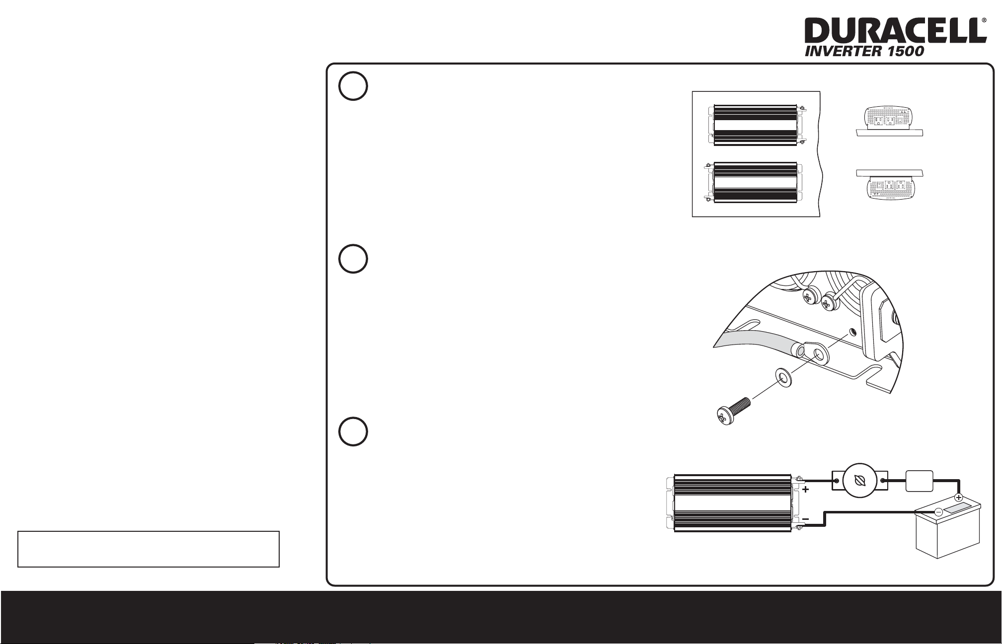
Mounting the inverter
1. Select an appropriate mounting location and orientation.
The Duracell® 1500 can be oriented:
• Horizontally on a vertical surface.
• On or under a horizontal surface.
2. Using the inverter as a guide, mark the mounting screw positions.
3. Pilot drill the four mounting holes.
4. Fasten the inverter to the mounting surface using four fasteners
sized #10 or larger.
2
Connecting the chassis ground cable
1. Remove chassis ground screw and star washer using #2 Phillips
screwdriver.
2. Strip 1/2" (13 mm) to 3/4" (19 mm) of insulation from each end of
copper chassis ground cable.
3. Attach the ring connector that will join the cable to the chassis
ground screw.
4. Fit the chassis ground screw through the star washer and the ring
connector back into the screw opening.
5. Tighten the chassis ground screw.
6. Connect other end of ground cable to vehicle chassis.
Connecting the DC cables
3
1. If using your own DC cables, use a crimping tool to prepare them
Installation steps
1. Mounting the inverter
2. Connecting the chassis ground cable
3. Connecting the DC cables
Important: For complete specifications, requirements,
and detailed procedures, please see the Owner's Guide.
with ring terminals or connectors.
2. Install a fuse and Disconnect/Battery Selector Switch on the positive cable.
3. Attach the positive cable to the positive DC terminal on the inverter.
4. Attach a short DC cable to the unconnected end of the DC fuse holder.
5. Observing polarity carefully, connect the other end of the cable from
the fuse holder to the positive battery terminal.
6. Connect the negative cable to the negative battery terminal.
7. Connect the other end of the negative cable to the negative DC
terminal on the inverter.
8. Use the Disconnect/Battery Selector switch to select a battery or battery bank.
Questions or problems? Call 1 408 987 6359 or go to www.xantrex.com/support
SWITCH
ON
OFF
FUSE OR
CIRCUIT
BREAKER
VEHICLE
STARTING
BATTERY
 Loading...