

Page 1
DR Series
Inverter/Charger
Installation &
Operators Manual
Page 2

Page 3

DR Series
Inverter/Charger
Table of Contents
Section Description Page
1.0 INTRODUCTION ..........................................................................1
Unpacking and Inspection................................................... 2
Model Identification and Numbering Conventions ............ 3
Certification .......................................................................... 4
2.0 INSTALLATION............................................................................ 5
Features ............................................................................ 5
Modified Sine Wave Power ........................................... 5
Battery Charger/AC Transfer Relay .............................. 5
Simplicity ........................................................................ 5
High Efficiency ............................................................... 5
Low Power Consumption ............................................. 5
Options ............................................................................ 5
RC4/RC8 ......................................................................... 5
DRI ............................................................................ 5
DRCB ............................................................................ 5
Pre-installation ..................................................................... 6
Location .......................................................................... 6
Mounting......................................................................... 6
Ventilation....................................................................... 6
Tools Required ............................................................... 7
Hardware/Materials Required ....................................... 7
Wiring ............................................................................ 7
AC Connections ............................................................. 7
DC Connections ............................................................. 7
Grounding ...................................................................... 7
AC Grounding .......................................................... 7
DC Grounding .......................................................... 7
Batteries ............................................................................ 8
Battery Location ............................................................ 8
Battery Temperature ...................................................... 8
Main Service Panel ............................................................... 10
Sub-Panel ............................................................................ 10
AC Circuit Breakers ............................................................. 10
DC Disconnect ...................................................................... 10
Wire Routing ......................................................................... 10
Inverter Mounting ................................................................. 11
Wiring ............................................................................ 13
DC Wiring (Batteries) ..................................................... 13
Battery Cable Sizing ...................................................... 13
DC Disconnect and Over-current Protection .............. 14
Battery Cable Connections ...........................................15
Battery Bank Sizing ....................................................... 16
Battery Types ................................................................. 16
Battery Configuration .................................................... 16
SERIES ..................................................................... 16
PARALLEL ............................................................... 16
SERIES-PARALLEL ................................................. 16
©2000 Xantrex Technology Inc.
i
Page 4

Continued
Section Description Page
2.0 INSTALLATION (continued)
Wiring the Batteries in Series ............................................. 17
Wiring the Batteries in Parallel ..................................... 18
Wiring the Batteries in Series-parallel ......................... 18
Series/Parallel Configurations and Cross-Tying .........20
Installation Guidelines ......................................................... 22
DC Circuit Grounding .......................................................... 23
General DC Grounding Requirements ......................... 23
Installing the Battery Temperature Sensor ........................ 24
Installing the Sensor...................................................... 24
AC Wiring ............................................................................ 25
Sub-panel and Conduit Installation .............................. 25
Input to the Inverter .......................................................25
AC Input Wiring to the Inverter ..................................... 27
AC Output Wiring to the Sub-panel .............................. 28
AC Input Wiring to the Utility Breaker Box ..................29
Generators ............................................................................ 30
Generator Requirements ............................................... 30
Basic 120 VAC Generator Hookup
(non-utility applications only) ................................ 31
Basic 120 VAC Utility/Generator Hookup..................... 32
Generator Connections
(to manual bypass switch) ............................... 32
Utility Connections (to manual bypass switch) .... 32
Inverter Connections
(to manual bypass switch) ............................... 32
Sub-panel Connections .......................................... 32
Series Stacking..................................................................... 34
3.0 OPERATION ............................................................................ 36
Front Panel Controls and Indicators .................................. 36
Power ON/OFF Switch ................................................... 36
Ports ............................................................................36
COM Port ........................................................................ 36
Remote Controls ..................................................... 36
Stacking Interface ................................................... 36
Battery Sense Port ......................................................... 37
Controls .......................................................................... 38
DC Controls ............................................................. 38
Battery Type Selector ....................................... 38
Switch Positions ............................................... 38
0 and 1Equalize 1 and 2.................................. 38
2Deep Cycle Lead Acid 2................................ 38
3Not Specified ................................................. 38
4GEL Cell 2 ...................................................... 39
5GEL Cell 1 ...................................................... 39
6PbCa - Lead Calcium .................................... 39
7Deep Cycle Lead Acid................................... 39
8NiCad 1 .......................................................... 39
NiCad 2 .............................................................. 39
SEARCH MODE WATTS Potentiometer ....................... 40
Battery Charger Rate ..................................................... 41
Over Discharge Protection/AC Transfer Voltage......... 42
Over Discharge Protection (ODP) ..........................42
AC Transfer Voltage ................................................ 43
©2000 Xantrex Technology Inc.ii
Page 5

Continued
Section Description Page
3.0 OPERATION (continued)
Battery Capacity............................................................. 45
LED Indicators ............................................................... 46
Inverter Mode LED - Green ..................................... 46
Over Temp LED - Red/Green .................................. 46
Battery Hi/Battery Low LED - Red/Green .............. 47
Charger LED - Orange/Green ................................. 47
Audible Indicator ........................................................... 47
Circuit Breakers .............................................................48
Start-up ............................................................................ 49
Charger Mode .......................................................................50
3-Stage Charging Process ............................................ 50
Bulk Charge ............................................................. 50
Absorption Charge .................................................. 50
Float Charge ............................................................ 50
Equalize Charging ......................................................... 51
Setting the Equalize Charge ................................... 51
4.0 TROUBLESHOOTING ................................................................. 53
5.0 APPENDIX ............................................................................ 55
Batteries ............................................................................ 55
Selection of a Battery Type ................................................. 55
Flooded Lead Acid (FLA) .............................................. 55
RV and Marine ......................................................... 55
Golf Cart ................................................................... 55
Industrial (electric forklift) ......................................55
Sealed Batteries ............................................................. 55
Gel Cell ..................................................................... 55
Absorbed Glass Mat ................................................ 55
NiCad and NiFe Batteries .............................................. 56
Battery Bank Sizing ............................................................. 57
Estimating Battery Requirements ................................ 57
Example ................................................................... 58
Typical Appliance Wattages ................................................ 60
Battery Care and Maintenance ............................................ 61
Charge Rate ................................................................... 61
Bulk Charge ................................................................... 61
Float Voltage................................................................... 61
Temperature Compensation ......................................... 61
Equalization Charging ................................................... 61
Replenish Water Levels................................................. 62
Clean Battery Cables and Posts ................................... 62
Torque Battery Connections ......................................... 62
Check Battery State of Charge ..................................... 63
Problem Loads ..................................................................... 64
Multiwire Branch Circuits .................................................... 66
Identifying Multiwire Branch Circuits .......................... 67
Correcting Multiwire Branch Circuit Wiring ................ 68
6.0 LIMITED WARRANTY ................................................................. 69
7.0 SERVICE INFORMATION ............................................................71
8.0 SPECIFICATIONS ........................................................................ 72
©2000 Xantrex Technology Inc.
iii
Page 6

Disclaimer of Liability
Since the use of this manual and the conditions or methods of installation, operation, use and
maintenance of the unit are beyond the control of Xantrex Technology Inc., the company does not
assume responsibility and expressly disclaims liability for loss, damage, or expense arising out of or
any way connected with such installation, operation, use or maintenance.
©2000 Xantrex Technology Inc.IV
Page 7
IMPORTANT SAFETY INSTRUCTIONS
This manual contains important safety instructions that should be followed during the installation
and maintenance of this product.
To reduce the risk of electrical shock, and to ensure the safe installation and operation of this
product, the following safety symbols have been placed throughout this manual to indicate dangerous conditions and important safety instructions.
WARNING - A dangerous voltage or condition exists in this area.
Use extreme caution when performing these tasks.
AVERTISSEMENT - Une tension ou condition dangereuse existe dans cette zone.
Faire preuve dextrême prudence lors de la réalisation de ces tâches.
CAUTION - This procedure is critical to the safe installation or operation of the unit. Follow these
instructions closely.
ATTENTION - Cette procédure est essentielle à linstallation ou lutilisation
de lunité en toute sécurité. Suivre ces instructions de près.
NOTE - This statement is important. Follow instructions closely.
NOTE - Cette déclaration est importante. Suivre les instructions de près.
·
All electrical work must be done in accordance with local, national and/or international electrical
codes.
·
Before installing or using this device, read all instructions and cautionary markings located in (or
on) the manual, the inverter, the controller, the batteries and the PV array.
·
Do not expose this unit to rain, snow or liquids of any type. This product is designed only for
indoor installation.
·
To reduce the chance of short-circuits when installing or working with the inverter, the batteries
or the PV array, use insulated tools.
·
Remove all jewelry such as rings, bracelets, necklaces, etc., prior to installing this system. This
will greatly reduce the chance of accidental exposure to live circuits.
·
The inverter contains more than one live circuit (batteries and AC line). Power may be present
at more than one source.
·
This product contains no user serviceable parts. Do not attempt to repair this unit.
·
Do not install 120 volt AC stand-alone inverters onto 120/240 volt AC multi-branch circuit wiring.
This could pose a fire hazard due to an overloaded neutral return wire in this configuration.
©2000 Xantrex Technology Inc.
SAVE THESE INSTRUCTIONS
V
Page 8

BATTERY SAFETY INFORMATION
·
Always wear eye protection, such as safety glasses, when working with batteries.
·
Remove all loose jewelry before working with batteries.
·
Never work alone. Have someone assist you with the installation or be close enough to come to
your aid when working with batteries.
·
Always use proper lifting techniques when handling batteries.
·
Always use identical types of batteries.
·
Never install old or untested batteries. Check each batterys date code or label to ensure age
and type.
·
Batteries are temperature sensitive. For optimum performance, they should be installed in a
stable temperature environment.
·
Batteries should be installed in a well vented area to prevent the possible buildup of explosive
gasses. If the batteries are installed inside an enclosure, vent its highest point to the outdoors.
·
When installing batteries, allow at least 1 inch of air space between batteries to promote cooling
and ventilation.
·
NEVER smoke in the vicinity of a battery or generator.
·
Always connect the batteries first, then connect the cables to the inverter or controller. This will
greatly reduce the chance of spark in the vicinity of the batteries.
·
Use insulated tools when working with batteries.
·
When connecting batteries, always verify proper voltage and polarity.
·
Do not short-circuit battery cables. Fire or explosion can occur.
·
In the event of exposure to battery electrolyte, wash the area with soap and water. If acid enters
the eyes, flood them with running cold water for at least 15 minutes and get immediate medical
attention.
·
Always recycle old batteries. Contact your local recycling center for proper disposal information.
©2000 Xantrex Technology Inc.VI
Page 9
1.0 INTRODUCTION
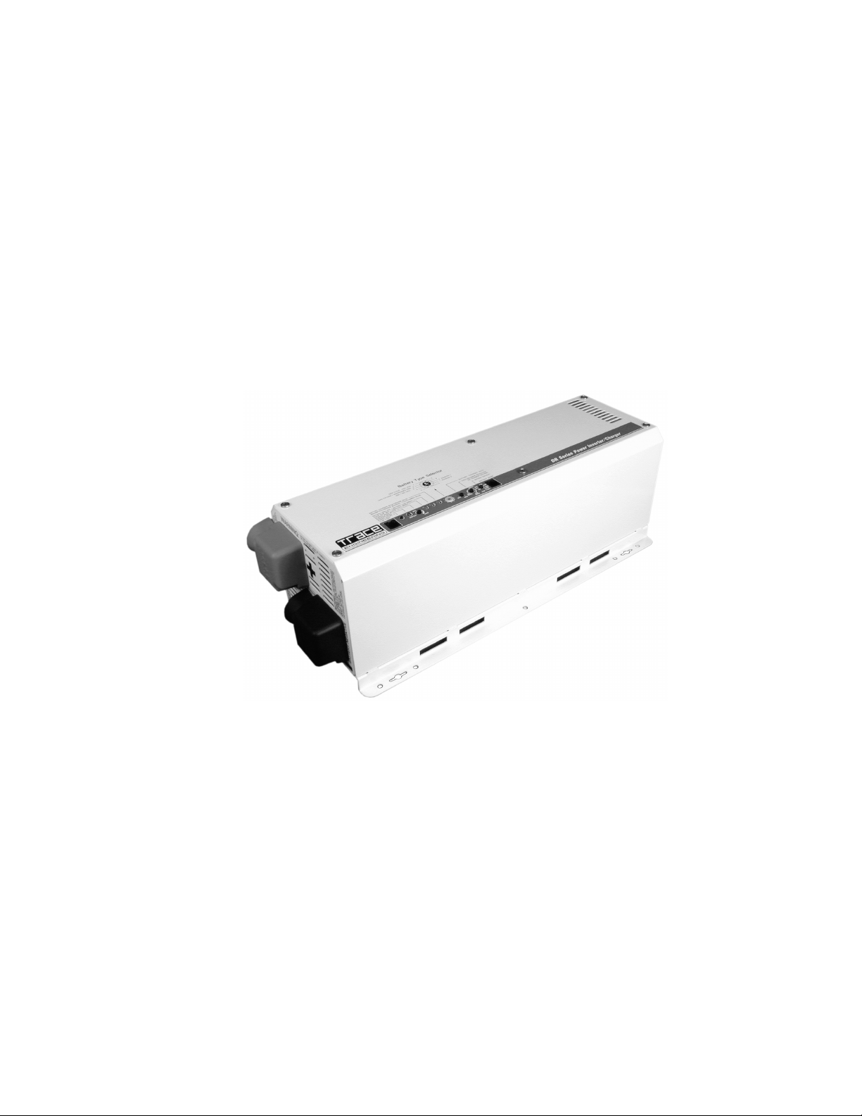
Thank you for purchasing the DR Series inverter/charger from Xantrex Technology Inc. The
DR Series is one of the finest inverter/chargers on the market today, incorporating state-of-the-art
technology and high reliability. The inverter features an AC pass-through circuit, powering your
home appliances from utility or generator power while charging the batteries. When utility power
fails, the battery backup system keeps your appliances powered until utility power is restored.
Internal protection circuits prevent over-discharge of the batteries by shutting down the inverter
when a low battery condition occurs. When utility or generator power is restored, the inverter
transfers to the AC source and recharges the batteries.
The front panel features LEDs for reading system status, and controls to customize the inverter
settings for your battery bank.
©2000 Xantrex Technology Inc.
Figure 1
The DR Series Inverter/Charger
1
Page 10

1.0 INTRODUCTION
Unpacking and Inspection
Carefully unpack the inverter/charger from its shipping carton.
NOTE: The unit weighs 3545 lb/15.920.4 kg (depending on model). Have additional help available
if necessary, to assist in lifting the unit during installation.
Verify all of the items listed on the packing material sheet are present. Please call Xantrex
Customer Service at (360) 435-8826 if any items are missing.
Save your proof-of-purchase. This is required if the unit should require warranty service.
Save the original shipping carton and packing materials! If the inverter ever needs to be returned
for service, it should be shipped in the original carton. This is also a good way to protect the
inverter if it ever needs to be moved.
Record the units model, serial number and date of purchase in the appropriate fields in section
10.0 SERVICE INFORMATION.
NOTE: Due to continual improvement through product updates, photographs and/or illustrations
used in this manual may not exactly match your unit. Xantrex Technology Inc. reserves the right to
update this product without notice or releasing an updated manual when fit, form or function are not
affected.
2
©2000 Xantrex Technology Inc.
Page 11
1.0 INTRODUCTION
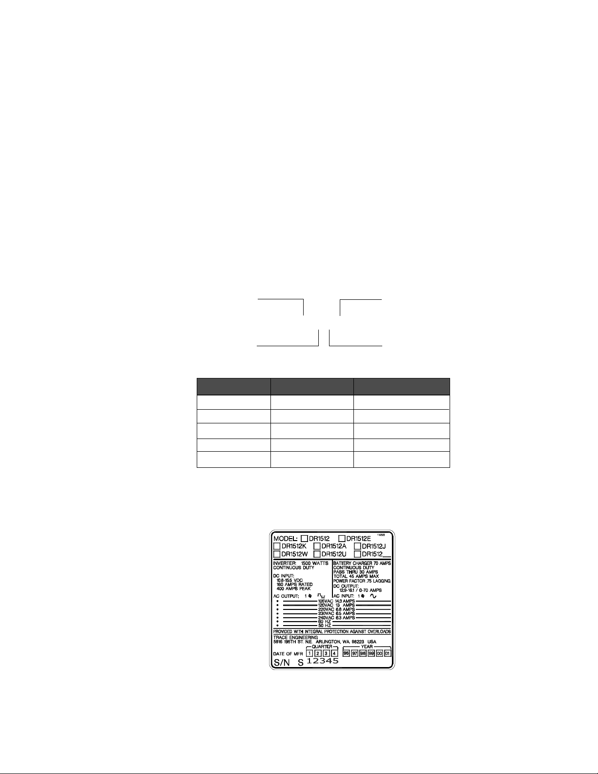
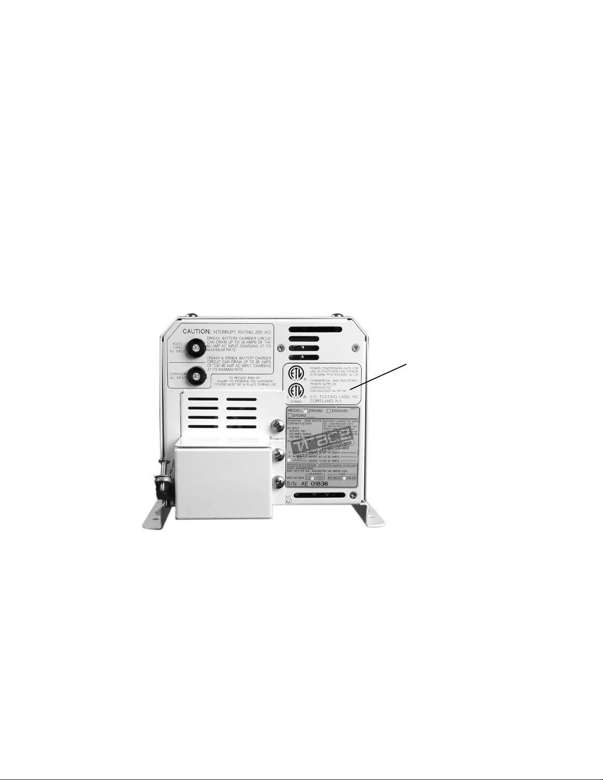
Model Identification and Numbering Conventions
The DR Series inverter/charger is identified by the model/serial number label located next to the
AC access cover. All the necessary information is provided on the label such as AC output voltage,
power and frequency (punch holes).
The inverter also has a letter designator followed by 4 or 5 digits (depending on revision). The
model number describes the type of inverter, the output specifications, the required battery voltage
and the output voltage and frequency.
DR indicates the type of inverter/charger - DR Series.
15 the first two digits of the numerical designator indicate the inverters output power - 1500
Watts.
12 the second two digits indicate the required nominal battery bank voltage - 12 VDC.
E the letter suffix code indicates the output voltage and frequency of the inverter - 230
VAC/50 Hz.
Product Family
Example: DR 1512 E
Output Power
Letter Suffix Output Voltage Output Frequency
(no letter) 120 VAC 60 Hz
E 230 VAC 50 Hz
J 105 VAC 50 Hz
K 105 VAC 60 Hz
W 220 VAC 60 Hz
Figure 2
Product Identification
Country Code
Battery Voltage
©2000 Xantrex Technology Inc.
Figure 3
Model/Serial Number Sticker
3
Page 12
1.0 INTRODUCTION
Certification
120 VAC/60 Hz models of the DR Series inverter/charger models are listed to UL Standard 1741,
Power Conditioning Units for use in Residential and Commercial Photovoltaic Power Systems. These
units are also ETL listed to CAN/CSA-22.2, No. 107.1-M91, the Canadian safety standard. These
standards guarantee that the inverter/charger has been tested to nationally recognized safety
standards (UL for the US and CSA for Canada) and have been found to be free from reasonably
foreseeable risk of fire, electric shock and related hazards.
The inverter/charger is intended to be used for residential or commercial applications. Do NOT
use this unit for applications for which it is not listed (i.e., land vehicles or marine craft). It may not
comply with the safety code requirements, or could possibly present other operational or safety
hazards.
Figure 4
UL/CSA Certification Sticker
Certification Sticker
4
©2000 Xantrex Technology Inc.
Page 13

2.0 INSTALLATION
The DR Series inverter/charger is an economical product designed to provide a reliable supply of
electricity to all the essential circuits in the home or business during a power outage. The critical
loads can be powered for hours or days, depending on the size of the system battery bank. When
utility grid power returns, the batteries are quickly recharged to ensure they will be ready to supply
backup power during the next outage.
Accessories allow the DR Series to also serve as a central hub of a renewable energy system.
Features
Modified Sine Wave Power
The DR Series inverters provide a modified sine wave output which operates most AC appliances
and equipment.
Battery Charger/AC Transfer Relay
The inverter/charger includes a 3-stage battery charger designed to recharge any type of battery
in the shortest possible time. The built-in, fully automatic AC transfer relay automatically transfers
power from the utility to the inverter and handles a full 60 amps of current at 120 VAC (30 amps
for pass-through plus 30 amps for charging).
Simplicity
The DR Series is simple to operate. All inverter and battery charger controls are located on the
front panel.
High Efficiency
The inverter/charger operates at over 90% efficiency through most of its power range.
Low Power Consumption
DR Series inverters use extremely low current while in the search mode, consuming little more
than one watt of power. In the ON mode, the inverter/charger uses less than 20 watts of power.
Options
The following options are available for the DR Series inverter/chargers:
RC4/RC8
The RC4/RC8 allows the inverter to be switched ON or OFF remotely and includes an LED status
indicator.
DRI
The DRI stacking interface provides 3-wire 120/240 VAC at twice the power using dual DR Series
inverters (120 VAC/60 Hz units only).
DRCB
The DRCB conduit box connects to the DC side of the inverter and accepts a DC conduit run.
©2000 Xantrex Technology Inc.
5
Page 14

2.0 INSTALLATION
Pre-installation
NOTE: Before installing the inverter/charger, read all instructions and cautionary markings located in
this manual.
NOTE: The inverter/charger can weigh up to 45 lb. (20.4 kg) depending upon configuration. Always
use proper lifting techniques during installation to prevent personal injury.
Location
Inverters contain sophisticated electronic components and should be located in a well
protected, dry environment away from sources of fluctuating or extreme temperatures and
moisture. Exposure to saltwater is particularly destructive and potentially hazardous.
NOTE: If the inverter is installed in a location where it is exposed to a corrosive or condensing
environment, and fails due to corrosion, it will not be covered under warranty.
Locate the inverter as close to the batteries as possible in order to keep the battery cable
length short. However, do not locate the inverter above the batteries or in the same
compartment as vented batteries. Batteries generate hydrogen sulfide gas which is corrosive
to electronic equipment. They also generate hydrogen and oxygen. If accumulated, an arc
caused by connecting the battery cables or switching a relay could ignite this mixture.
Mounting the inverter in a ventilated enclosure with sealed batteries is acceptable.
NOTE: Inverters can generate RFI (Radio Frequency Interference). Locate any sensitive electronic
equipment susceptible to RFI as far away from the inverter as possible. This includes radios and
TVs.
Mounting
UL Standard 1741 requires the inverter be mounted on a vertical surface (or wall). The
keyhole slots must not be used as the only method of mounting. The purpose of the wall
mounting requirement is to orient the inverter so that its bottom cover, which has no holes,
will not allow burning material to be ejected in the event of an internal fire. Use 0.25 inch
diameter bolts for mounting. The mounting surface must be capable of supporting twice the
weight of the inverter to comply with UL 1741.
Ventilation
Install the inverter in a well ventilated area/enclosure for proper operation. The inverters
thermal shutdown point will be reached sooner than normal in a poorly ventilated
environment, resulting in reduced peak power output and surge capability, as well as shorter
inverter life.
The inverter contains an internal fan. Ensure the air vents and intakes are not obstructed in
any way. Provide a minimum clearance of 1-1/2 inches around the top and sides of the
inverter for ventilation.
6
©2000 Xantrex Technology Inc.
Page 15

2.0 INSTALLATION
Pre-Installation (continued)
Tools required:
#2 Phillips screw driver Level
Slotted screw driver Wire strippers
Assorted open-end wrenches Torque wrench
Socket wrench and fittings Electrical tape
Multimeter (True rms) Pencil
Hole saw Utility knife
Hardware / Materials required:
4 ft. x 4 ft. sheet of 3/4" plywood or 2 x 4s studding material
#12 wood screws (or 1/2" x 1-1/4" lag bolts)
Conduit and appropriate fittings
Wire nuts
Wiring:
All wiring and installation methods should conform to applicable electrical and building codes.
Pre-plan the wire and conduit runs. The AC circuits accept cable sizes up to #6 AWG. The DC
circuits accept cable sizes up to #4/0 AWG.
For maximum safety, run both AC and DC cables in conduit.
Refer to the Figure 25 (page 29) for an example of AC wiring to the sub-panel for 120 VAC
circuits.
AC Connections:
Use #6 AWG THHN wire for all AC wiring.
DC Connections:
Battery to inverter cabling should be only as long as required. If #4/0 AWG cables are used
for example, do not exceed 5 feet (one way) in 12 VDC systems; do not exceed 10 feet (one
way) in 24 VDC systems. For optimum performance, use pre-assembled battery cables
designed specifically for this application (available from Xantrex).
Grounding:
AC Grounding
The inverter/charger should be connected to a grounded, permanent wiring system. Neutral
and ground conductors should only be bonded at the main utility service panel.
DC Grounding
The negative battery conductor should be bonded to the grounding system at only one point
in the system. The size for the conductor is usually based on the size of the largest conductor
in the DC system.
©2000 Xantrex Technology Inc.
7
Page 16

2.0 INSTALLATION
Pre-Installation (continued)
Batteries:
The battery voltage MUST match the voltage requirements of the inverter. To determine the
correct voltage for the system, check the last two digits on the inverters model number. For
example, the DR1512 is a 12 volt inverter and requires a 12 VDC battery system. The
DR2424 is a 24 volt inverter and requires a 24 VDC battery system.
Battery Location:
Locate the batteries in an accessible location. Two feet clearance above the batteries is
recommended for access to the battery caps. They should be located as close to the inverter
as possible without limiting access to the inverters disconnects. Install the batteries to the left
of a wall mounted inverter for easy access to the DC side of the inverter and shorter cable
runs.
For safety and to limit access to the batteries, a lockable, ventilated, battery enclosure or
dedicated room should be used. If an enclosure is used, it should be vented to the outside
via a one inch vent pipe located at the top of the enclosure. Install an intake vent at the
bottom of the enclosure to promote air circulation. These vents exhaust explosive hydrogen
gases and must not be overlooked when designing an enclosure.
The enclosure should be made of an acid resistant material or have a finish that resists acid
to prevent corrosion. It should be capable of holding the electrolyte from at least one battery
should a leak occur.
Place a layer of baking soda on the shelves to neutralize any acid that may be spilled in the
future (lead-acid batteries only).
Enclosures located outside must be rainproof and screened to prevent access by rodents or
insects.
Battery Temperature
The battery enclosure should provide a fairly stable temperature for the batteries. If it is installed
in a cold environment, insulation should be used to protect the batteries from the cold. The insulation
also provides a more consistent temperature and better system performance.
The battery enclosure should not be installed in direct sunlight where the summer sun can
overheat the batteries. Locate the enclosure where it will be protected from the afternoon sun and
provide vents in the top and bottom of the enclosure to provide air flow. High battery
temperatures greatly shortens the life of the batteries.
8
©2000 Xantrex Technology Inc.
Page 17
Pre-Installation (continued)
DISCONNECT
DC CONDUIT
(if used)
BATTERIES
BATTERY
ENCLOSURE
(if used)
2.0 INSTALLATION
CONDUIT
VENT
(outlet)
BOX
(if used)
INVERTER/CHARGER
MAIN PANEL
AC CONDUIT
FROM MAIN
PANEL
AC CONDUIT TO SUB-PANEL
SUB-PANEL
DC
VENT
(inlet)
DC
DISCONNECT
AND PVGFP
DC CHARGE
CONTROLLER
SOLAR
ALTERNATE DC ENERGY SOURCES
DC CONDUIT
(if used)
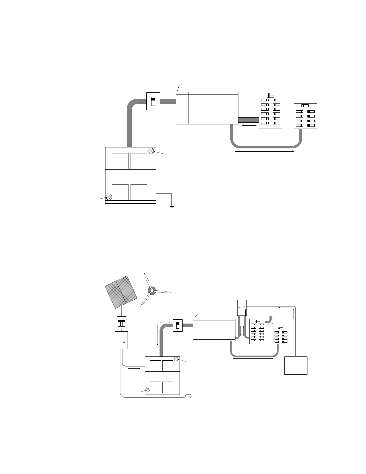
Figure 5
Planning Example Layout
Basic Setup
WIND
CONDUIT
VENT
(outlet)
BOX
(if used)
INVERTER/CHARGER
BATTERY
ENCLOSURE
(if used)
DC CONDUIT
(if used)
BATTERI ES
DC
DISCONNECT
MANUAL AC
TRANSFER
SWITCH
N.C.
COM.
N.O.
AC CONDUIT
AC CONDUIT TO SUB-PANEL
FROM GENERATOR
MAIN PANEL
975-0012-001
AC CONDUIT
UTILITY
SUB-PANEL
AC GENERATOR
(externally located)
DC GROUND
WIRE
©2000 Xantrex Technology Inc.
VENT
(inlet)
GROUND
DC
975-0012-002
Figure 6
Planning Example Layout
RE Setup
9
Page 18

2.0 INSTALLATION
Main Service Panel:
The input to the inverter requires a minimum 60 amp breaker (for each inverter if stacked). This
circuit breaker must be located in the utility service panel.
Sub-Panel:
Loads backed up by the inverter will need to be rerouted from the main service panel to a sub-
panel. This can be done several different ways, depending upon the installation. Always refer to
electrical codes for safe wiring practices.
AC Circuit Breakers:
Always use a properly rated circuit breaker. Depending upon the application, circuit breakers
used to protect the load can be removed from the main service panel and put into the sub-panel
ONLY if the two panels are from the same manufacturer.
DC Disconnect:
Install a DC disconnect breaker or fuse in the positive battery line. This breaker protects the DC
wiring in the event of an accidental short. Size the breaker in accordance with the battery cables.
Switch this breaker OFF whenever servicing the batteries.
Wire Routing:
Determine all wire routes both to and from the inverter and which knockouts are best suited for
connecting the AC conduits. Possible routing scenarios include:
AC Input wiring from the main utility service panel to the inverter/charger
AC Input wiring from the generator to the inverter/charger (if used)
DC Input wiring from the PV array (wind, hydro, etc.) to the inverter/charger (if used)
DC Input wiring from the batteries to the inverter/charger
AC Output wiring from the inverter/charger to the sub-panel
Battery Temperature Sensor cable from the batteries to the inverter/charger (if used)
Remote Control cable to the inverter/charger (if used)
DC Ground from the batteries to an external ground rod
Load circuit wiring rerouted from the main service panel to the sub-panel
Check for existing electrical or plumbing prior to making cuts in the walls. Cut holes in the walls
at appropriate locations for routing wiring/cables.
10
©2000 Xantrex Technology Inc.
Page 19
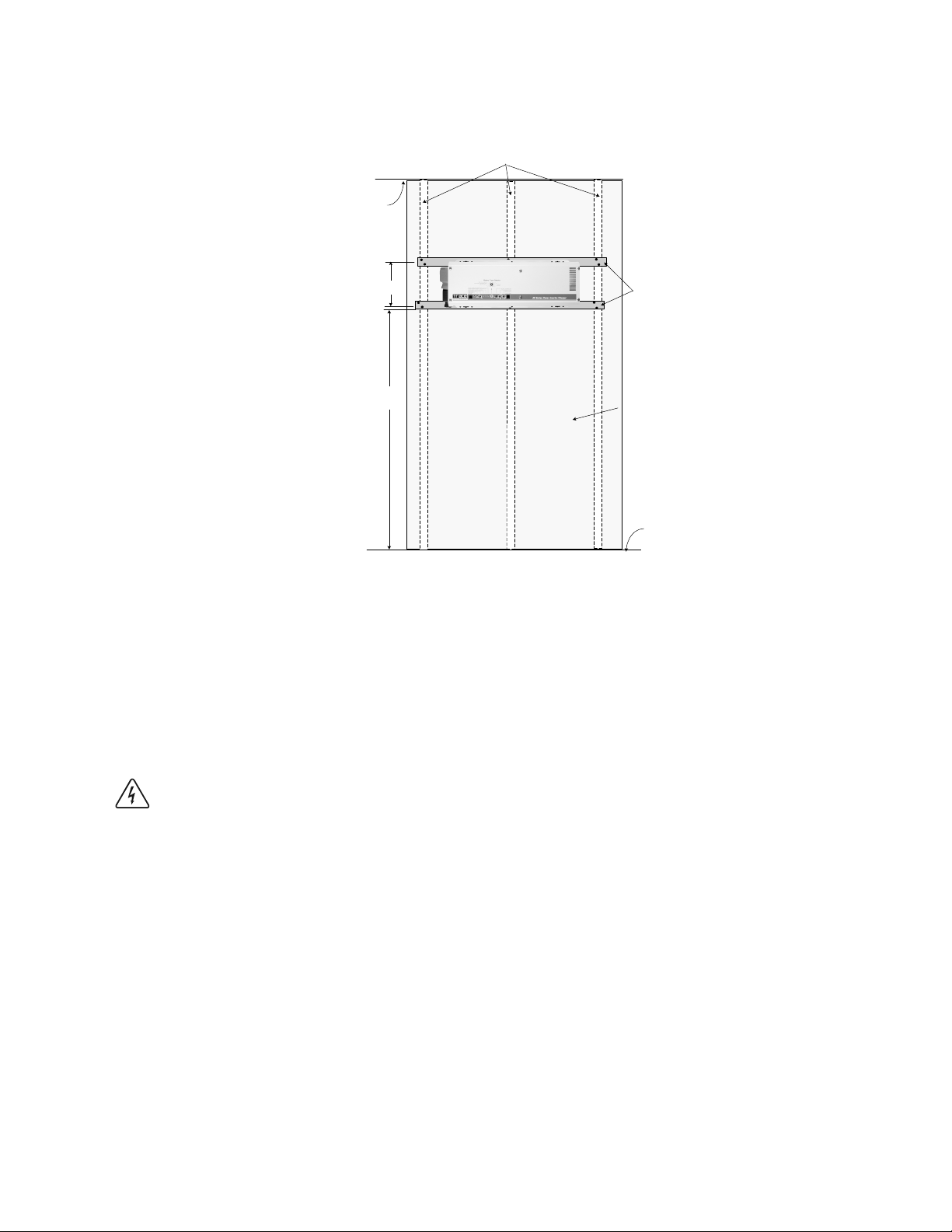
Inverter Mounting (continued)
Ceiling
Wall studs 16 inches on
center
2.0 INSTALLATION
7–5/8" c-c
Approximately
4–5 ft
975-0012-003
2 x 4 mounting
supports
Wallboard
Floor
Figure 7
Suggested Mounting Method
Inverter Mounting
The DR Series inverter can weigh as much as 45 lb. (20.4 kg). Wallboard is not strong enough
to support its weight so additional support must be added. The easiest method for securing it to an
existing wall is to place two 2 x 4s horizontally on the wall (spanning at least three studs) and
securing the inverter to the 2 x 4s.
WARNING: USE APPROPRIATE LIFTING TECHNIQUES. HAVE EXTRA PEOPLE ON HAND TO
ASSIST IN LIFTING THE INVERTER INTO POSITION WHILE IT IS BEING SECURED.
Procedure
Locate the studs and mark their location on the wall.
Measure the desired height from the floor for the inverter to be mounted.
Using a level, run a horizontal line. The length of the line must span at least 3 studs.
Place a pre-cut 2 x 4 on the marked location and drill pilot holes through the 2 x 4s and
studs.
Secure the 2 x 4 with #10 wood screws (length to penetrate 1-1/2 inches into the studs).
Repeat the procedure for the remaining 2 x 4.
©2000 Xantrex Technology Inc.
11
Page 20
2.0 INSTALLATION
s
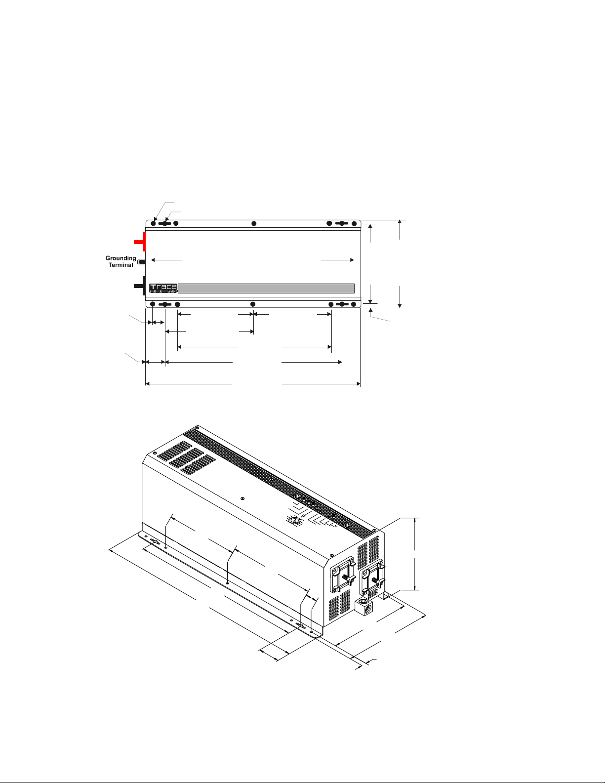
Referring to Figure 8, drill out the mounting hole locations for the inverter.
With assistance, lift the inverter into position and install it onto the 2 x 4s using 1/4 x 1-1/2
inch lag bolts and washers.
Alternatively, a half or quarter sheet of 3/4 inch plywood can also be used as a backing, with the
inverter mounted directly to the plywood using 1/4 inch diameter lag bolts and washers. The plywood
must span three studs for adequate support.
0.281 DIA 10 PLACES
0.375 DIA 4 PLACES
+
TERMINAL
–
TERMINAL
DC SIDE
AC SID E
21.25 cm
19.40 cm
8.370 inches
7.640 inches
1.00 inches
2.54 cm
1.90 inches
4.83 cm
7.00 inches
17.8 cm
8.00 inches
20.32 cm
7.00
16.00
20.175
14.00 inches
35.56 cm
16.00 inches
40.64 cm
20.175 inches
51.244 cm
8.00
7.00 inches
17.8 cm
1.00
0.365 inche
0.93 cm
975-0012-D-011
G
N
I
R
E
E
N
I
G
N
E
E
C
A
R
T
R
E
E
N
I
G
N
E
E
C
A
R
T
6.970
G
N
I
12
7.640
.281 DIA. 5 PLACES
8.370
.375 DIA. 2 PLACES
1.900
0.365
975-0012-D-012
Figure 8
Dimensional Drawings for Screw Hole Placement
©2000 Xantrex Technology Inc.
Page 21
2.0 INSTALLATION
Wiring
DC Wiring (Batteries)
Battery Cable Sizing
Proper cable sizing (diameter and length) is critical to the safe and efficient operation of an
inverter system. Larger diameter cables (smaller AWG number) have less voltage drop and are,
therefore, more efficient when transferring power to and from the batteries. If a cable is undersized
(diameter too small), it could potentially overheat, creating a fire hazard.
Cable length is another important factor. Runs should be kept as short as practical. Longer
cable runs increase resistance, thus lowering the overall efficiency of the system. This is especially
true in lower voltage systems (i.e., 12 VDC) where, depending upon the length of the cable run, it
may be necessary to oversize the diameter of the wire, or parallel (double) the cables.
Always use a properly sized cable and length rated for the amperage of the inverter and
batteries.
WARNING: UNDERSIZED CABLES CAN OVERHEAT AND MELT, CREATING A FIRE HAZARD
WHEN SUBJECTED TO HEAVY (PEAK) LOADS.
NOTE: If the system will be operated at the inverters peak power rating exceeding one hour, larger
cables and disconnects MUST be used (see Tables 1 and 2).
NOTE: If the system includes a large battery bank or large DC source (such as a micro-hydroelectric
plant or wind generator), increasing the size of the cables and disconnects will greatly reduce the
number of nuisance outages associated with breaker tripping and open fuses.
Table 1 provides recommended minimum cable sizes for various cable lengths and inverter
amperages. These recommendations may not meet all local or NEC requirements.
NOTE: Use only copper cables.
NOTE: Run the positive and negative battery cables as close to each other as possible by taping
them together. This reduces the effects of inductance and produces a better waveform thus
increasing efficiency.
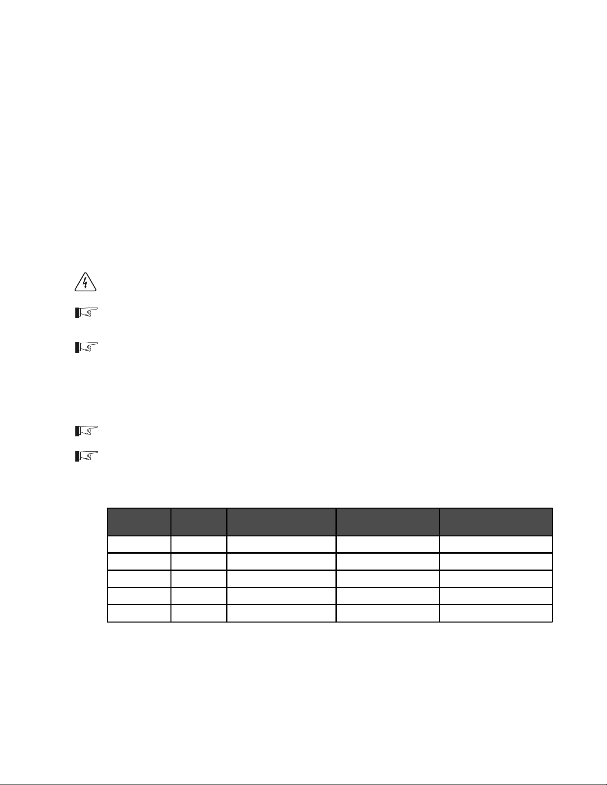
Inverter
Model
DR1512
DR2412
DR1524
DR2424
DR3624
Typical
Amperage
150 A #2/0 AWG (67.4 mm
240 A #4/0 AWG (107 mm
75 A #2/0 AWG (67.4 mm
120 A #2/0 AWG (67.4 mm
180 A #4/0 AWG (107 mm
1 to 3 Feet (one-way) 3 to 5 Feet (one-way) 5 to 10 Feet (one-way)
2
) #2/0 AWG (67.4 mm2) #4/0 AWG (107 mm2)
2
) #4/0 AWG (107 mm2) NOT RECOMMENDED
2
) #2/0 AWG (67.4 mm2) #4/0 AWG (107 mm2)
2
) #4/0 AWG (107 mm2) #4/0 AWG (107 mm2)
2
) #4/0 AWG (107 mm2) #4/0 AWG (107 mm2)
975-0012-004
Minimum Recommended Battery Cable Size VS. Length
©2000 Xantrex Technology Inc.
Table 1
13
Page 22
2.0 INSTALLATION
Wiring (continued)
DC Disconnect and Over-current Protection
For safety and to comply with regulations, battery over-current protection is required. Fuses and
disconnects must be sized to protect the wiring in the system and are required to open before the
wire reaches its maximum current carrying capability.
The National Electrical Code (NEC) requires both over-current protection and a disconnect
switch for residential and commercial electrical systems. These items are not supplied as part of the
inverter. However, Xantrex offers a DC rated, DC250/175 ETL listed, circuit breaker disconnect
module specifically designed for use with Trace inverters to meet NEC compliance. Two amperage
ratings are available: a DC250 (250 amps) and a DC175 (175 amps) in either single or dual breaker
configurations for single or dual inverter installations.
NOTE: Trace DC disconnects are not designed to accept doubled (paralleled) cables which may
be required for long cable runs. Also, the plastic red and black covers on the DC inverter inputs are
not designed to accommodate dual cables. If dual cables are used, the optional conduit box (DRCB)
must be used.
Some installations may not require conduit or a disconnect device, although over-current
protection is still required. Xantrex offers a fuse block (TFB) providing the code required inverter
over-current protection for these applications. Refer to the table below for the proper size disconnect
device for specific cable diameters.
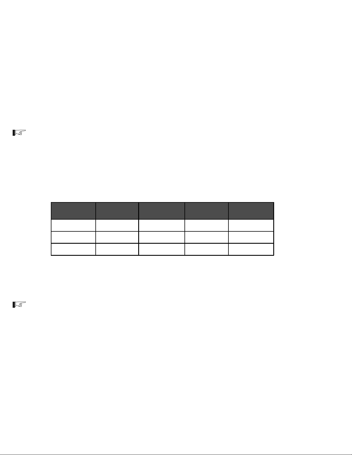
Cable Size
Required
#2 AWG 115 amps max N/A 170 amps max TFB200
#2/0 AWG 175 amps max DC175 265 amps max TFB300
#4/0 AWG 250 amps max DC250 360 amps max TFB400
Rating in
Conduit
Maximum
Breaker Size
Rating in "Free
Air"
Maximum Fuse
Size
975-0012-005
Table 2
Battery Cable to Maximum Breaker/Fuse Size
NOTE: The NEC allows rounding to the next standard fuse size from the cable rating (i.e., 150 amp
cable size rounds up to a standard 175 amp size). The term free air is defined by the NEC as
cabling that is not enclosed in a conduit or a raceway. Cables enclosed in conduit or raceways have
substantially lower continuous current carrying ability due to heating factors.
14
©2000 Xantrex Technology Inc.
Page 23
2.0 INSTALLATION
Wiring (continued)
Battery Cable Connections
Battery cables must have crimped (or preferably, soldered and crimped) copper compression
lugs unless aluminum mechanical lugs are used. Soldered connections alone are not acceptable.
High quality, UL-listed battery cables are available from Trace Engineering in an assortment of
lengths: 1-1/2 to 10 feet, and in #2/0 AWG or #4/0 AWG sizes. These cables are color-coded with
pressure crimped, sealed ring terminals.
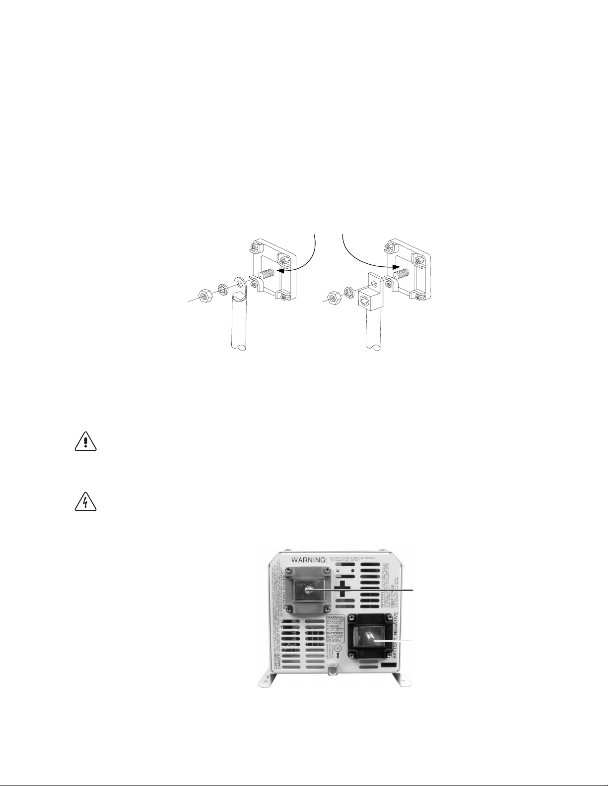
Figure 9 illustrates the proper method to connect the battery cables to the DR Series inverter/
charger terminals.
Do not place anything
between battery cable lug
and terminal surface.
Assemble exactly as shown.
2/0 Copper Compression Lug 2/0 Aluminum Mechanical Lug
Figure 9
Battery Cable Connections to Inverter
CAUTION: THE INVERTER IS NOT REVERSE POLARITY PROTECTED. REVERSING THE
BATTERY POLARITY ON THE DC INPUT CONNECTIONS WILL CAUSE PERMANENT DAMAGE
TO THE INVERTER WHICH IS NOT COVERED UNDER WARRANTY. ALWAYS CHECK
POLARITY BEFORE MAKING CONNECTIONS TO THE INVERTER.
WARNING: ENSURE THE INVERTER IS OFF BEFORE CONNECTING OR DISCONNECTING
THE BATTERY CABLES, AND THAT AC POWER IS DISCONNECTED FROM THE INVERTER
INPUT.
POSITIVE (+) RED TERMINAL
NEGATIVE (-) BLACK TERMINAL
©2000 Xantrex Technology Inc.
Figure 10
Battery Cable Connections
15
Page 24

2.0 INSTALLATION
Wiring (continued)
Battery Bank Sizing
The size of the battery bank determines how long the AC loads will operate in a backup mode
without utility power. The larger the battery bank, the longer the run time. Size the battery bank to the
systems AC load requirements and length of time required to run from the batteries. In general, the
battery bank should not be discharged more than 50%. Additional DC charging devices such as
solar, wind, hydro, etc., can provide longer run times by recharging the batteries in the absence of
AC utility or generator power.
Additional details on estimating battery bank size and capacity can be found in the Appendix
section of this manual.
Battery Types
Batteries are available in different sizes, amp-hour ratings, voltage, liquid or gel, vented or nonvented, chemistries, etc. They are also available for starting applications (such as an automobile
starting battery) and deep discharge applications. Only the deep discharge types are recommended
for inverter applications. Choose the batteries best suited for the inverter installation and cost. Use
only the same battery type for all batteries in the bank. For best performance, all batteries should be
from the same lot and date. This information is usually printed on a label located on the battery.
Additional information regarding batteries can be found in the Appendix section of this manual.
Battery Configuration
The battery bank must be wired to match the inverters DC input voltage specifications (12, 24 or
48 VDC). In addition, the batteries can be wired to provide additional run time. The various wiring
configurations are:
SERIES
Wiring batteries in series increases the total bank output voltage (to match the inverters DC
requirements).
PARALLEL
Wiring the batteries in parallel increases the total run time the batteries can operate the AC loads.
SERIES-PARALLEL
Series-parallel configurations increase both the battery voltage (to match the inverters DC
requirements) and run-time for operating the AC loads.
16
©2000 Xantrex Technology Inc.
Page 25
2.0 INSTALLATION
Wiring (continued)
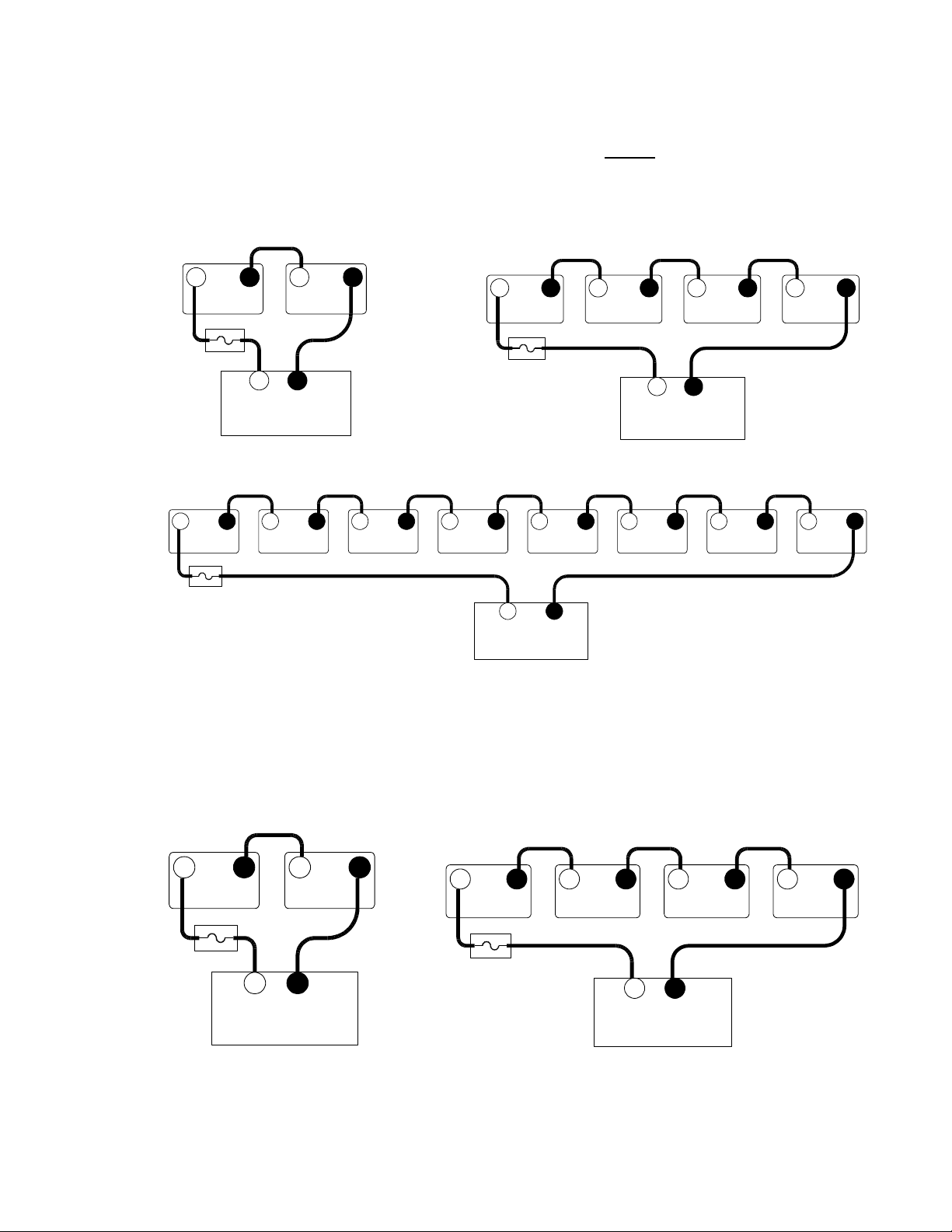
Wiring Batteries in Series
Wiring the batteries in a series configuration increases the voltage of the battery string. 6 volt
batteries can be combined to form 12 V, 24 V, or 48 V battery banks. In the same way, 12 volt
batteries connected in series form 24 V or 48 V battery banks. The total current capacity of the bank
does not increase and it retains the same amp-hour rating as a single battery.
+ - + -
6 V 6 V
+ -
12 V INVERTER
(Total battery capacity = 100 Ah)
+ - + -
6 V 6 V
+ - + -
6 V 6 V
Each batterys amp-
hour rating is 100 Ah
3597-F00-D21
+ - + -
6 V 6 V
+ - + -
6 V 6 V
+ -
48 V INVERTER
(Total battery capacity = 100 Ah)
Figure 11
6 Volt Battery WiringSeries Configuration
+ - +
6 V 6 V
+ -
24 V INVERTER
(Total battery capacity = 100 Ah)
+ - + -
-
3597-F00-D22
6 V 6 V
3597-F00-D23
+ - + -
12 V 12 V
+ -
24 V INVERTER
(Total battery capacity = 50 Ah)
©2000 Xantrex Technology Inc.
+ - + -
12 V 12 V
(Total battery capacity = 50 Ah)
3597-F00-D24
Each batterys amp-hour
rating is 50 Ah
Figure 12
12 Volt Battery WiringSeries Configuration
+ - + -
12 V 12 V
+ -
48 V INVERTER
3597-F00-D25
17
Page 26
2.0 INSTALLATION
Wiring (continued)
Wiring Batteries in Parallel
Wiring the batteries in a parallel configuration increases the current of the battery string. This is
commonly used in 12 volt configurations. The voltage of the battery bank remains the same as an
individual battery. Parallel configurations extend the run times of the AC loads by providing
increased current for the inverter to draw from. In a parallel configuration, all of the negative battery
terminals are connected together and all of the positive battery terminals are connected together.
–
+
–
12 V
+
–
12 V
+
–
12 V
12 V
+
Each batterys amp-hour
rating is 50 Ah
+ –
12 V INVERTER
(Total battery capacity = 200 Ah)
3597-F00-D26
Figure 13
12 Volt Battery WiringParallel Configuration
Wiring Batteries in Series-Parallel
Wiring the batteries in a series-parallel configuration increases the
current and voltage of the
battery bank. Series-parallel wiring is more complicated and care should be taken when wiring these
banks.
To construct a series-parallel battery bank follow these instructions:
Step 1
First wire the batteries in series (voltage adds) with the positive terminal of one battery
connected to the negative terminal of the next battery to meet the inverters DC input
requirements.
18
Repeat this step for the next battery string.
Two identical strings of batteries are now wired in series.
+ – + –
12 V 12 V
+ – + –
12 V 12 V
+ – + –
12 V 12 V
+ – + –
12 V 12 V
Figure 14
Step 1Wire Batteries in Series
Series String 1
Series String 2
3597-F00-D27
©2000 Xantrex Technology Inc.
Page 27

2.0 INSTALLATION
Wiring (continued)
Wiring Batteries in Parallel (continued)
Step 2
Connect the POSITIVE terminal of the first battery string to the POSITIVE terminal of the
second battery string.
Connect the NEGATIVE terminal of the first battery string to the NEGATIVE terminal of the
second battery string.
–
Parallel
Connection
+
12 V 12 V
+ –
+ – + –
12 V 12 V
Series String 1
Parallel
Connection
+ – + –
12 V 12 V
+ – + –
12 V 12 V
3597-F00-D28
Series String 2
Figure 15
Step 2Two Series Strings Wired in Parallel
Step 3
Connect a wire from the POSITIVE terminal of the first battery string to the inverters
POSITIVE DC terminal (via a fused device).
Connect the NEGATIVE terminal of the second battery string to the inverters NEGATIVE DC
terminal.
NOTE: Connecting the positive and negative wires to the inverter from different strings ensures a
balanced charge/discharge through the batteries, resulting in longer run times and improved battery
life.
Connection from
bank 1 to inverter
positive (+)
terminal
+
– + –
12 V 12 V
+ – + –
12 V 12 V
Step 3Series-Parallel Configuration Wired to the Inverter
©2000 Xantrex Technology Inc.
+
– + – + – +
12 V 12 V
+ –
48 V INVERTER
(Total batt ery capacity = 100 Ah)
Figure 16
–
12 V 12 V
Connection from
bank 2 to inverter
negative ()
terminal
3597-F00-D29
19
Page 28
2.0 INSTALLATION
Wiring (continued)
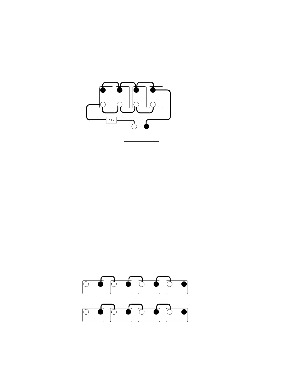
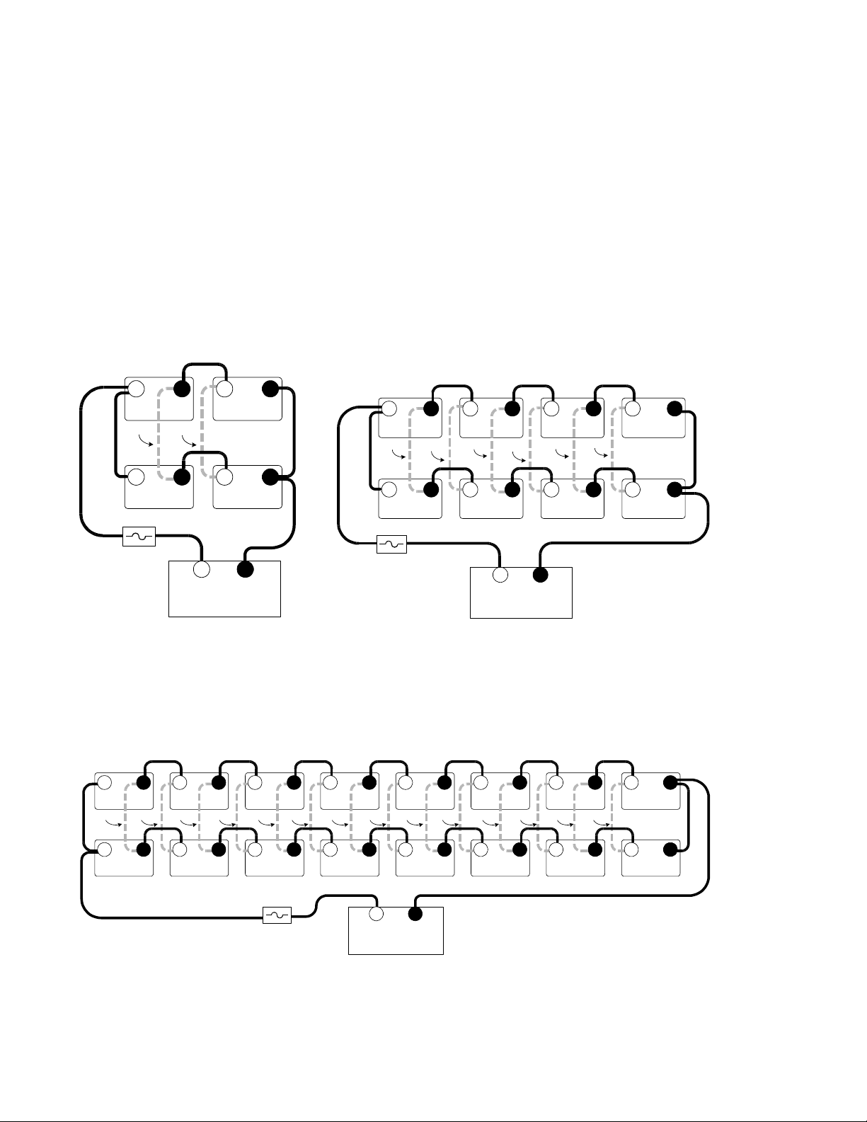
Series/Parallel Configurations and Cross-Tying
To reduce the imbalances between the batteries in a series/parallel bank and improve the
overall battery bank performance, the batteries can be cross-tied. In this arrangement, the batteries
wired in the series part of one string are also wired in parallel with the batteries in the second string
making each battery in the bank a (parallel) pair. This technique is not a requirement, but can
improve the overall performance of the batteries and further increase the battery life as each battery
receives a more even charge/discharge cycle. However, cross-tying the batteries involves additional
expense of the extra battery cables and labor to wire them.
Cross-tying is shown in the following series/parallel configurations and is indicated by a light,
dashed line. If cross-tying is not desired, ignore these dashed lines.
+ – + –
6 V
Cross-tie cable
(not required)
Cross-tie cable
(not required)
6 V
+ – + – + – + –
6 V
Cross-tie cable
(not required)
Cross-tie cable
(not required)
6 V
Cross-tie cable
(not required)
Cross-tie cable
(not required)
6 V
Cross-tie cable
(not required)
Cross-tie cable
(not required)
6 V
+ +–
6 V 6 V
Fuse Block
Disconnect
+
6 V 6 V
Cross-tie cable
Cross-tie cable
(not required)
(not required)
+
6 V 6 V 6 V 6 V 6 V 6 V 6 V 6 V
+ –
12 V INVERTER
(Total battery capacity = 200 Ah)
– + – + – + – + – +++ ––
Cross-tie cable
Cross-tie cable
(not required)
(not required)
– + – + – + – + – +++ ––
–
+ + – + – + ––
6 V 6 V 6 V 6 V
Fuse Block
Disconnec t
3597-F00-D33
6 V 6 V 6 V 6 V 6 V
Cross-tie cable
Cross-tie cable
Cross-tie cable
Cross-tie cable
Cross-tie cable
(not required)
(not required)
(not required)
(not required)
(not required)
Cross-tie cable
(not required)
+ –
24 V INVERTER
(Total battery capacity = 200 Ah)
Cross-tie cable
Cross-tie cable
(not required)
(not required)
Cross-tie cable
(not required)
Cross-tie cable
(not required)
3597-F00-D31
–
6 V
–
20
+ –
Fuse Block
Disconnect
48 V INVERTER
(Total battery capacity = 200 Ah)
Figure 17
6 Volt Battery WiringSeries/Parallel Configuration
(with optional cross-tie wiring)
3597-F00-D32
©2000 Xantrex Technology Inc.
Page 29

Wiring (continued)
Cross-Tying Series/Parallel Configurations (continued)
+ – + –
12 V
Cross-tie cable
(not required)
Cross-tie cable
(not required)
12 V
2.0 INSTALLATION
+ +–
–
12 V 12 V
Fuse Block
Disconnect
+ –
24 V INVERTER
(Total battery capacity = 100 Ah)
3597-F00-D34
+ – + – + – + –
12 V
Cross-tie cable
Cross-tie cable
(not required)
(not required)
+ + – + – + –
–
12 V
Cross-tie cable
(not required)
Cross-tie cable
(not required)
12 V
Cross-tie cable
(not required)
Cross-tie cable
(not required)
12 V 12 V 12 V 12 V
12 V
12 Volt Battery WiringSeries/Parallel Configuration
©2000 Xantrex Technology Inc.
Fuse Block
Disconnect
+ –
48 V INVERTER
(Total battery capacity = 100 Ah)
Figure 18
(with optional cross-tie wiring)
3597-F00-D30
21
Page 30

2.0 INSTALLATION
Installation Guidelines
WARNING: ENSURE THE INVERTER IS OFF BEFORE CONNECTING OR DISCONNECTING
THE BATTERY CABLES AND THAT ALL AC POWER IS DISCONNECTED FROM THE
INVERTERS INPUTS.
Determine the correct size battery cable to use for installation from Table 1.
Determine the correct size disconnect/fuse for installation from Table 2.
Color code the cables with tape or heat shrink tubing. The standard colors are red for positive (+)
and black for negative (-).
Connect the negative cable to the batterys negative terminal (torque to manufacturers
recommendations).
Install the over-current device (fuse or circuit breaker) between the batterys positive terminal and
the inverters positive terminal (as close to the batteries as possible).
Connect the (short) positive cable to the batterys positive terminal (torque to manufacturers
recommendations).
Ensure the correct polarity of the cables with a DC voltmeter (DVM).
Observing battery polarity, connect the positive battery cable (from the over-current device) to
the inverters positive terminal.
NOTE: The next step may cause a small spark and snapping sound when connecting the cable to
the inverter. This is normal, and is caused by the inverters capacitors charging up.
Observing battery polarity, connect the negative battery cable to the inverters negative terminal.
Use an insulated 1/2 inch wrench or socket to tighten the 5/16 SAE nuts to 10-15 foot/lb for each
inverter input terminal.
CAUTION: DO NOT PUT ANYTHING BETWEEN THE CABLE RING TERMINAL AND THE FLAT
METAL PART OF THE TERMINAL. OVERHEATING OF THE TERMINAL MAY OCCUR. DO NOT
APPLY ANY TYPE OF ANTIOXIDANT PASTE UNTIL AFTER THE BATTERY CABLE WIRING IS
TIGHTENED.
Apply antioxidant paste to the battery and inverter terminals.
Install the battery terminal connection covers (red for positive, black for negative) over the
inverters DC terminals and secure with the screws and washers provided.
22
©2000 Xantrex Technology Inc.
Page 31

2.0 INSTALLATION
DC Circuit Grounding
Grounding is an important part of the system installation and must be performed correctly to
ensure safe operation of the equipment. Grounding requirements vary by country and application.
Consult the NEC for specific requirements.
The ground conductor should be sized appropriately for the over-current protection device
being used and according to NEC 250-95 (see table below for a portion of the NEC code).
Size of Over-current
Device Protecting the
Conductor
Minimum Size of
Copper Ground Wire
30 or 60 amp #10 AWG
100 amp #8 AWG
200 amp #6 AWG
300 amp #4 AWG
400 amp #3 AWG
3597-000-018
Table 3
Safety Ground Wire Size
General DC Grounding Requirements
Connect the negative (-) terminal of the battery bank to an appropriately sized conductor and
connect it to a solid earth ground, such as a grounding rod, driven 68 feet into the earth.
This procedure will properly ground the DC circuits.
©2000 Xantrex Technology Inc.
+
&LUFXLW%UHDNHU
+
-
+
-
7
1
+
$
;
Figure 19
DC Grounding
5
$
;
;
(
-
-
;
(
5
7
1
&KDVVL V*URXQG
+
;
(
5
7
1
$
;
-
*URXQG
5RG
23
Page 32
2.0 INSTALLATION
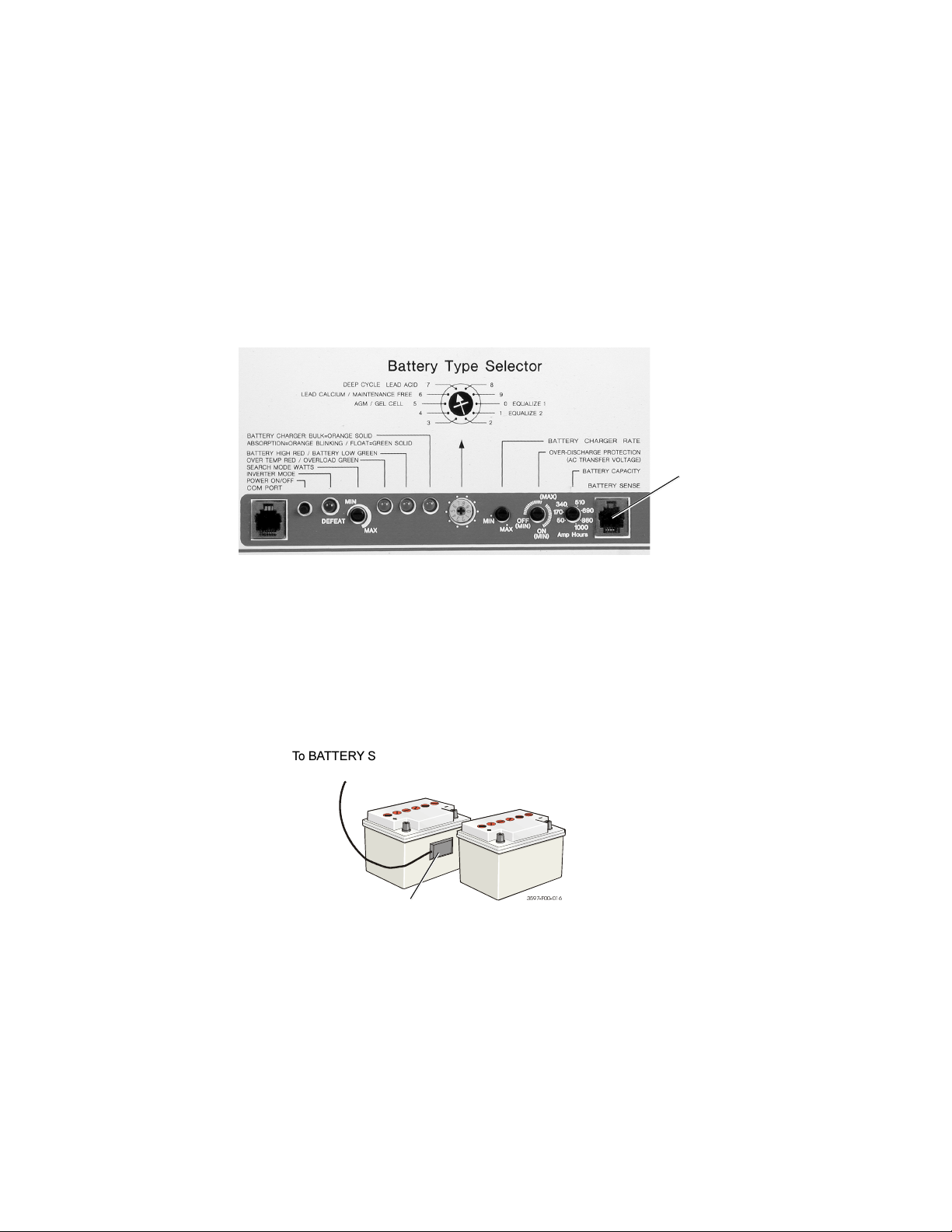
Installing a Battery Temperature Sensor
A battery temperature sensor (BTS) option can easily be installed in the system to ensure
proper charging of the batteries based on temperature. Installing a BTS extends battery life by
preventing overcharging in warm temperatures and undercharging in cold temperatures.
Installing the sensor:
Run the battery temperature sensor wire in the DC conduit (if used) and route the RJ11
connector end to the BATTERY SENSE jack located on the front of the inverter.
Secure the sensor to one of the batteries located in the center the battery pack.
BATTERY SENSE
(RJ11) Jack
Figure 20
BTS (RJ11) Jack Location
To BATTERY SENSE
jack
BTS connected to
battery
Figure 21
BTS Installed on Battery
)
24
©2000 Xantrex Technology Inc.
Page 33

2.0 INSTALLATION
AC Wiring
Sub-panel Mounting and Conduit Installation
NOTE: The installation of sub-panels and wiring should be performed by a qualified person or a
licensed electrician following all local and NEC codes.
Determine the location of the sub-panel and install it according to the manufacturers
directions.
Install the AC conduit between the sub-panel (output) and inverter.
WARNING: DISCONNECT THE POWER FROM THE UTILITYS MAIN BREAKER BOX BEFORE
PROCEEDING.
Install conduit between the inverter (input) and the main breaker box.
Determine which circuits require backup. Install the appropriate circuit breakers into the
sub-panel.
Install a 60 amp (disconnect) circuit breaker in the sub-panel. This will later be wired to the
inverters output. If two inverters are being used in a stacked configuration, install two 60
amp circuit breakers for 240 VAC service (one in each leg of the circuit for L1 and L2).
Input to the Inverter
CAUTION: THE INVERTERS AC OUTPUT MUST NEVER BE WIRED TO THE UTILITY OR
GENERATOR OUTPUT. THIS WILL CAUSE SEVERE DAMAGE TO THE INVERTER WHICH IS
NOT COVERED UNDER WARRANTY.
All AC wiring connects to the terminal block located on the right-hand side of the inverter.
To access the terminal block, remove the side cover panels (if installed) by removing the
two (or three) Phillips screws. Units are shipped without the covers installed (packed in a
small plastic bag with additional hardware).
Locate the AC input and output terminals on the block. Refer to Figure 23.
NOTE: The lower AC cover varies depending on the systems power level. Higher power units are
equipped with a conduit box and not a plate. The conduit box is required for the larger diameter
wire providing ample bending radius.
Screws
Standard Cover Plate
©2000 Xantrex Technology Inc.
High Power Conduit Box
Figure 22
AC Wiring Access Cover Plates
25
Page 34
2.0 INSTALLATION
AC Wiring
Before wiring the input of the inverter, refer to the table below for the minimum recommended
wire size.
NOTE: Refer to the NEC for actual wire sizes for specific installations.
AC Input AC Output
Inverter Model
120 VAC 220-240 VAC 120 VAC 220-240 VAC
DR1512
DR2412
DR1524
DR2424
DR3624
#8 or 6 AWG #10 AWG #12 AWG #16 AWG
#6 AWG #10 AWG #10 AWG #14 AWG
#8 or 6 AWG #10 AWG #12 AWG #16 AWG
#8 AWG #10 AWG #10 AWG #14 AWG
#6 AWG Not Available #8 AWG Not Available
975-0012-007
Table 4
Minimum Recommended Wire Size (Input and Output)
26
©2000 Xantrex Technology Inc.
Page 35

2.0 INSTALLATION
AC Wiring (continued)
NOTE: The U.S. requires conduit be used in this type of installation. Refer to the NEC and local
codes. Conduit fittings can be replaced with strain reliefs where code permits.
Refer to the table on the previous page for minimum recommended wire sizes.
Procedure
AC Input Wiring to Inverter
WARNING: DISCONNECT THE BATTERY CONNECTIONS FROM THE INVERTER IF THEY ARE
ALREADY CONNECTED.
ALL WIRING SHOULD BE PERFORMED BY A QUALIFIED OR LICENSED ELECTRICIAN.
DISCONNECT THE MAIN BREAKER AT THE MAIN UTILITY BREAKER BOX.
Install a 60 amp circuit breaker in the utility service panel. This will serve as both an AC
disconnect and over-current protection.
Feed the HOT, NEUTRAL and GROUND wires (via conduit) from the inverter to the main
utility box. Leave several inches of extra wire at each end.
Make the connections to the inverter first. Wiring to the utility breaker box is performed after
all connections have been made in the inverter.
Connect the GROUND (green) wire to the inverters AC GROUND terminal.
Connect the NEUTRAL (white) wire from the main utility panel to the inverters NEUTRAL
INPUT terminal.
Connect the HOT (black) wire from the main utility panel to the inverters AC HOT INPUT
terminal.
Torque all connections to 16 inch-pounds.
AC CHASSIS
GROUND
HOT
IN
NEUTRAL
IN
©2000 Xantrex Technology Inc.
Figure 23
AC Input Wiring
27
Page 36

2.0 INSTALLATION
AC Wiring (continued)
AC Output Wiring to the Sub-panel
WARNING: ENSURE THE SUB-PANEL DOES NOT HAVE A NEUTRAL TO GROUND BOND. IF IT
DOES, REMOVE IT. ALL AC NEUTRAL-GROUND BONDING IS DONE AT THE MAIN UTILITY
BREAKER BOX (SERVICE ENTRANCE).
Connect the GROUND wire to the inverters AC GROUND chassis terminal. Connect the
other end of this wire to the GROUND bus in the sub-panel.
Connect the NEUTRAL (white) wire to the inverters NEUTRAL OUTPUT terminal. Connect
the other end of this wire to the NEUTRAL bus in the sub-panel.
Connect the HOT (black) wire to the inverters terminal labeled AC HOT OUTPUT. Connect
the other end of this wire to the sub-panels input circuit breaker.
Torque all inverter terminal block connections to 16 inch-pounds. Refer to the sub-panel
manufacturers specifications for wire torques.
AC CHASSIS
GROUND
NEUTRAL
OUT
HOT
OUT
Figure 24
AC Output Wiring
NOTE: The two neutral connections (input and output) are common to one another and may be used
in any combination.
28
©2000 Xantrex Technology Inc.
Page 37

2.0 INSTALLATION
AC Wiring (continued)
AC Input Wiring to the Main Utility Breaker Box (single inverter installations)
WARNING: MAKE CERTAIN THE POWER TO THE MAIN UTILITY BOX IS DISCONNECTED!
NEVER WORK ON LIVE CIRCUITS.
Remove the MAIN UTILITY BOXs cover plate.
Connect the ground (green) wire to the GROUND bus in the main utility box.
Connect the neutral (white) wire to the NEUTRAL bus.
Connect the hot (black) wire to the 60 amp circuit breaker (installed for the inverter).
Torque all wires to the manufacturers specifications.
CAUTION: INSPECT ALL WIRING FOR PROPER INSTALLATION BEFORE REINSTALLING THE
COVER PLATE.
UTILITY FEED
FROM METER
LINE
NEUTRAL
1
MAIN PANEL
120 VAC
120 VAC
240 VAC
NEUTRAL BONDED TO GROUND
EARTH GROUND
NOTE: FOR ILLUSTRATIVE PURPOSES ONLY.
BREAKER BOXES VARY DEPENDING ON APPLICATION.
MAIN PANEL WIRING TO NON-CRITICAL LOADS
IS NOT ILLUSTRATED.
MAIN
BREAKER
CAUTION:
IN MAIN PANEL ONLY!
EXISTING HOUSE WIRING
FROM
UTILITY
120 VAC FROM
LINE OUT
LINE OUT
120 VAC BACKUP POWER
NEUTRAL
GROUND
INVERTER/CHARGER
GROUND
120 VAC LINE IN
NEUTRAL
LINE OUT
120 VAC INVERTER OUT
INVERTER
DISCONNECT
TO LOAD
NEUTRAL
GROUND
SUB PANEL
120 VAC BACKUP POWER
TO LOAD
(NEW WIRING)
120 VAC LINE OUT
NEUTRAL
GROUND
©2000 Xantrex Technology Inc.
NEUTRAL
GROUND
3597-W00-C06
Figure 25
Single Inverter 120 VAC Wiring Diagram
29
Page 38

2.0 INSTALLATION
Generators
An AC generator can be used as an input source instead of the utility power, or can be
connected (via additional hardware) to power the loads when utility is not present (utility outage),
and to charge the batteries. The generator must be of the permanently installed type and not a
portable type unit used for emergency power. Small emergency type generators may not have a
stable enough voltage or frequency output for the inverter to synchronize to, or provide enough
current to fully charge the batteries.
Generator Requirements
The maximum charge rate the battery charger can deliver is dependant upon the peak AC
voltage available. Since the battery charger uses only the top portion of the input sine wave,
small variations in peak voltage result in large variations in the amount of energy to the charger.
The chargers rated output is based on a utility voltage of 120 VAC
169 VACp (230 VAC
has a peak voltage of 325 VACp).
rms
Low power generators may not produce enough voltage under heavy load conditions to fully
charge the batteries as the voltage peaks may be clipped, limiting the maximum charge rate. Size
the generator appropriately for the system, including battery charge and load current.
The following table demonstrates how the peak voltage available affects the charging current:
which has a peak voltage of
rms
Peak Voltage
Av ai la b le
170 VAC
DR1512 DR2412 DR1524 DR2424 DR3624
70 amps 120 amps 35 amps 70 amps 70 amps
P
Table 5
Peak Input Voltage vs Charging Current
Generator Type Inverter Type
Typical MAX charge
Rate amps
Honda 800 DR1512 43 amps
Honda 2200 DR1512 57 amps
Homelite 2500 DR1512 11 amps
Honda 3500 DR1512 39 amps
Honda 6000 DR1512 70 amps
Honda 1600 DR1524 25 amps
Westerbeke 7.0 kW DR1512 Approx. 45 amps
975-0012-012
30
Westerbeke 12.5 kW DR1512 Approx. 65 amps
975-0012-013
Table 6
Generator Types
©2000 Xantrex Technology Inc.
Page 39

2.0 INSTALLATION
Generators (continued)
Because generator hookups can vary widely, only basic hookup information is given. Complex
hookups, involving both the utility and generator, require additional hardware such as a manual AC
transfer switch and possibly an autotransformer for load balancing.
Basic 120 VAC Generator Hookup (non-utility applications only)
Connect the ground wire on the generator to the GROUND terminal on the inverter.
Connect the generator neutral wire to the NEUTRAL terminal on the inverter.
Connect the generator HOT wire to the HOT input on the inverter.
Bond the neutral to the ground on the output of the generator (only if used in non-utility
installations) or in the MAIN SERVICE PANEL (not both).
Drive a ground rod 68 feet into the ground and connect the generators ground to the
ground rod.
NOTE: The ground and neutral must be bonded at one place, and only one place, in the system. If
the generator is the main source of power, (i.e., no utility grid power) then the neutral and ground
connections are bonded at the generator. If the generator is acting as a backup for the utility grid,
then the bond should be at the main utility service entrance box. In this case, ensure that no bond
exists at the generator output.
Manually start the generator and check for proper operation of the inverter (i.e., the inverter
transfers from battery to generator power).
120 VAC
GENERATOR
Neutral/
Ground bond
HOT
Neutral
Ground
HOT
Neutral
Ground
Distribution
120 VAC
LOADS
INVERTER/
CHARGER
HOT
Neutral
Ground
Panel
3597-A00-016
Basic 120 VAC Generator Block Diagram (for non-utility applications)
©2000 Xantrex Technology Inc.
Figure 26
31
Page 40

2.0 INSTALLATION
Generators (continued)
Basic 120 VAC Utility/Generator Hookup
If a generator is used as a backup for the utility, then a manual transfer switch must be added
to provide a means to switch the generator power to the inverters inputs. The generator can be
used during extended outages to recharge the batteries and provide pass through power for the
loads. Start and stop the generator manually using the generators pull-cord, ON/OFF switch, etc.
Generator Connections (to manual bypass switch)
Connect a (green) ground wire between the generators GROUND terminal and the
GROUND terminal in the manual bypass switch.
Connect a (white) neutral wire between the generators NEUTRAL terminal and the
NEUTRAL bus in the manual bypass switch.
Connect a (black - HOT) wire between the generators HOT OUT terminal and the
GENERATOR (HOT) contact in the manual bypass switch.
NOTE: Refer to the bypass switch installation manual for contact details, torque specifications, etc.
Utility Connections (to manual bypass switch)
Connect a (green) wire between the GROUND terminal in the MAIN UTILITY PANEL and the
GROUND terminal in the manual bypass switch.
Connect a (white) wire between the NEUTRAL bus in the MAIN UTILITY PANEL and the
NEUTRAL bus in the manual bypass switch.
Connect a (black) wire between the inverter circuit breaker in the MAIN UTILITY PANEL and
the UTILITY HOT contact in the manual bypass switch.
Inverter Connections (to manual bypass switch)
Connect a (green) wire between the GROUND terminal in the manual bypass switch and the
inverters AC GROUND terminal.
Connect a (white) wire between the NEUTRAL terminal in the manual bypass switch and the
inverters NEUTRAL IN terminal.
Connect a (black) wire between the COMMON terminal in the manual bypass switch and the
inverters HOT IN terminal.
Torque all wires 16 in/lb.
Sub-panel Connections
Connect a (green) wire between the inverters AC GROUND terminal and the GROUND
terminal in the sub-panel.
Connect a (white) wire between the inverters NEUTRAL OUTPUT terminal and the
NEUTRAL bus in the sub-panel.
Connect a (black) wire between the inverters terminal labeled AC HOT OUTPUT and the
SUB-PANELs INPUT circuit breaker.
32
Torque all inverter terminal block connections to 16 inch-pounds. Refer to the sub-panel
manufacturers specifications for wire torques.
Recheck all connections.
Refer to the illustration on the next page.
©2000 Xantrex Technology Inc.
Page 41

Generators (continued)
Utility Power
120 VAC
2.0 INSTALLATION
Bonded Neutral/
Ground Bus
House
Ground
Generator
Power
Main Utility
G
Circuit
R
O
Breaker
U
N
D
Bond
Wire
Manual
Start
Generator
HOT
Inverter Circuit
Breaker
Utility Service
Panel
GENERATOR
HOT CONT ACT
HOT
NEUTRAL
NEUTRAL
N
E
U
T
R
A
L
NEUTRAL
HOT
UTILITY HOT
CONTACT
U
G
AC Input
COMMOMN
CONTACT
(to inverter)
Inverter
Manual Transfer
Switch
C
Isolated
Neutral Bus
Isolated
Neutral Bus
©2000 Xantrex Technology Inc.
AC Output
Main Input
Breaker
Neutral Bus
Sub-panel
Figure 27
Basic 120 VAC Utility/Generator Block Diagram
Isolat ed
NEUTRAL
HOT
GROUND
To AC Load
975-0012-008
33
Page 42
2.0 INSTALLATION
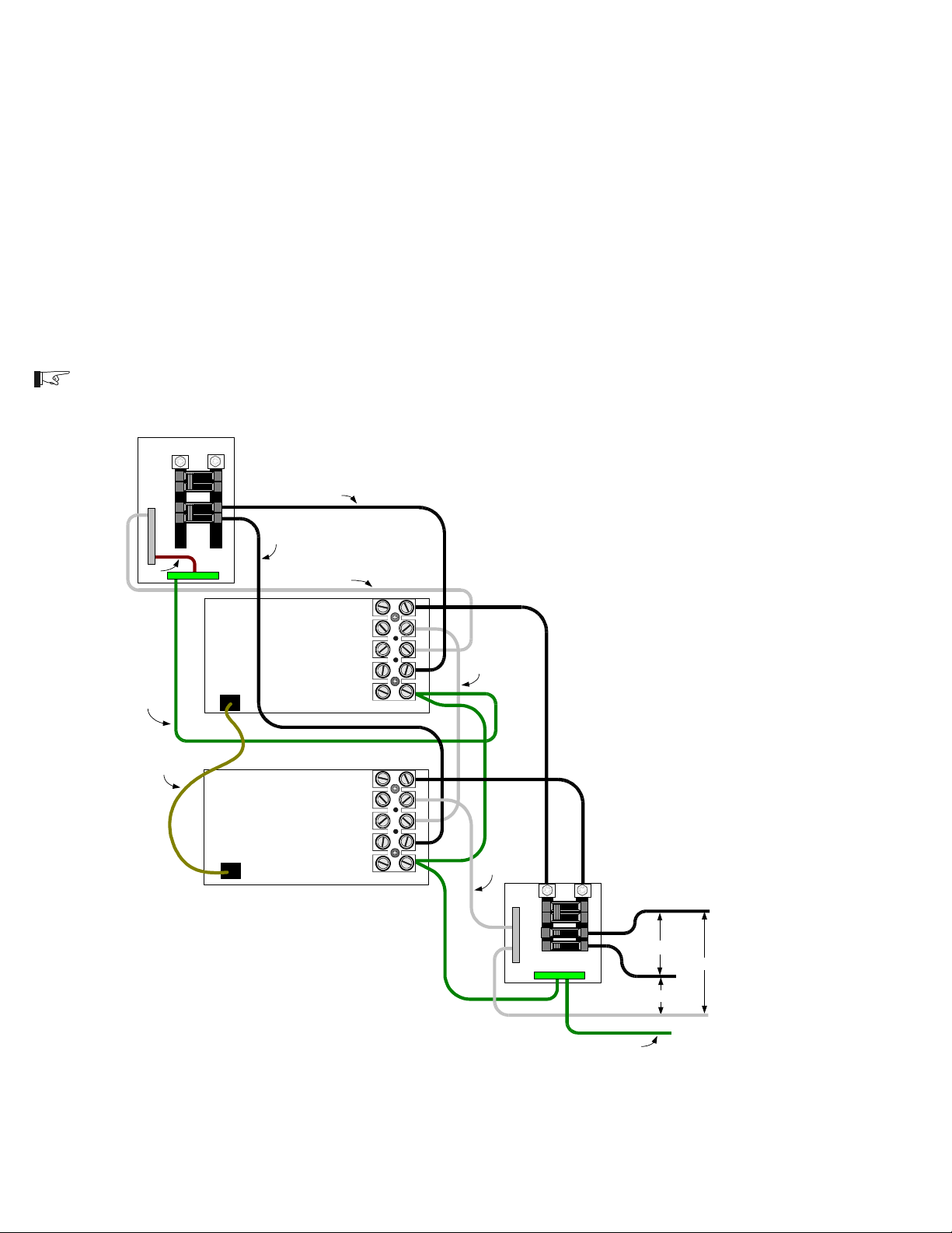
Series Stacking
This COM port allows two DR Series inverter/chargers to be used in the same system in a
SERIES configuration to operate 240 VAC loads. Series stacking can also be used to connect to
240 VAC only power systems providing both 120 and 240 VAC outputs. A series stacking interface
cable (DRI) is required to connect the series stacking port of the inverters. In this mode, one of the
inverters will function as the primary and the other inverter becomes the secondary. The first unit
switched ON becomes the primary and ensures the secondarys output is 180 degrees out of phase
for 240 VAC operation. Both units can charge the batteries or provide battery backup power during a
utility outage.
The following illustrations provide a general overview of AC and DC wiring configurations and
output voltages supplied by stacked inverters. Detailed wiring and operating instructions are
provided with the DRI interface kit available from Xantrex Technology Inc.
NOTE: Only 120 VAC/60 Hz models can be stacked.
MAIN PANEL
L2
L1
N
E
U
T
R
A
L
BOND
GROUND
WIRE
GROUND
SERIES STACKING
CABLE (DRI)
DRI
COM PORT
DRI
COM PORT
L1
L2
HOT L2
HOT L1
NEUTRAL I N
HOT OUT
NEUTRAL OUT
NEUTRAL IN
HOT IN
GROUND
INVERTER 1 (L1)
HOT OUT
NEUTRAL OUT
NEUTRAL IN
HOT IN
GROUND
INVERTER 2 (L2)
NEUTRAL OUT
NEUTRAL OUT
N
E
U
T
R
A
L
L1
SUB-PANEL
GROUND
L2
L1
240 VAC
L2
120 VAC
120 VAC
34
GROUND
975-0012-D-014
Figure 28
Series Stacking AC Wiring
(120 VAC/60 Hz models only)
©2000 Xantrex Technology Inc.
Page 43

Series Stacking (continued)
Positive
Tie
Negative
Tie
2.0 INSTALLATION
Inverter 1
(L1)
Series Stacking
Cable (DRI)
DC
Disconnect
–
+
–
+
–
+
–
+
Figure 29
Stacking Port and Battery Wiring with One Disconnect
(120 VAC/60 Hz models only)
Inverter 2
(L2)
975-0012-009
Inverter 1
(L1)
DC
Disconnect
Stacking Port and Battery Wiring with Two Disconnects
©2000 Xantrex Technology Inc.
+
+
DC
Disconnect
–
–
Negative
Tie
–
+
–
+
Figure 30
(120 VAC/60 Hz models only)
Series Stacking
Cable (DRI)
Inverter 2
(L2)
975-0012-010
35
Page 44

3.0 OPERATION
Front Panel Controls and Indicators
All operating controls, indicators and sense connectors are located on the front panel of the unit.
The controls are easily accessible, and the LEDs provide inverter/charger status at a glance.
POWER ON/OFF Switch
The POWER ON/OFF control is a momentary contact switch that turns the inverter/charger
ON or OFF by pressing it once. When the inverter is first connected to the batteries, it will run
through a self test consisting of flashing the LEDs in sequence, operating the cooling fan
momentarily and switching the transfer relay three times. Once the self test has successfully
completed, the POWER ON/OFF switch is activated. Pressing the switch once turns the inverter
ON. Another press turns the inverter OFF.
Ports
There are two ports on the inverter/charger. Both ports are RJ11 type telephone style
connectors and are used for controlling the inverter and regulating the charger voltage based on
temperature.
COM PORT
COM PORT (J1) is a dual function RJ11 (6-pin) connector. Its primary function is to
provide serial communications to an optional Trace remote control unit (RC4 or RC8). The
port also acts as a stacking interface control when two DR Series inverters are used in a
series configuration. When two inverters are stacked, a remote control cannot be used with
either unit.
Remote Controls (RC4 or RC8)
DR Series inverters are designed to operate with either an RC4 or RC8 remote control
units. Both remotes incorporate a membrane switch with a single red LED display
combination to start and stop the inverter, as well as provide overall system operating status.
Solid
With AC line power present, the unit is charging the batteries while directing AC to
the load. With no AC line power present, the inverter is running on the batteries and
supplying AC to the load.
Blinking Slow (1 to 3 flashes @ 1 second intervals)
The inverter is in search mode (no load connected).
Blinking Fast (3 to 5 flashes @ 1 second intervals)
The inverter is charging the batteries.
Flickering (3 to 5 flashes @ 1 second intervals)
The inverter has detected an over-current error. The LED (and inverter) will turn OFF
whenever an over-current condition exceeds eight seconds.
Erratic Blinking (0 to 3 and 2 to 5 flashes @ 2 second intervals)
The inverter has detected an error condition caused by overheating, low battery
voltage, or high battery voltage.
OFF
The inverter is OFF.
The remote control must be connected prior to switching the inverter ON; otherwise, the
micro-controller will not recognize (or respond to) the remote. If the remote is not recognized,
switch the inverter OFF and then ON using the inverters front panel POWER ON/OFF
switch.
Stacking Interface
Whenever two DR Series inverters are used in a series (stacked) configuration, one unit
(primary) controls the other unit (secondary). Communication between the two inverters is done
via the COM port (J1). The first unit switched ON, using its front panel POWER ON/OFF switch,
becomes the controlling (primary) inverter.
36 ©2000 Xantrex Technology Inc.
Page 45
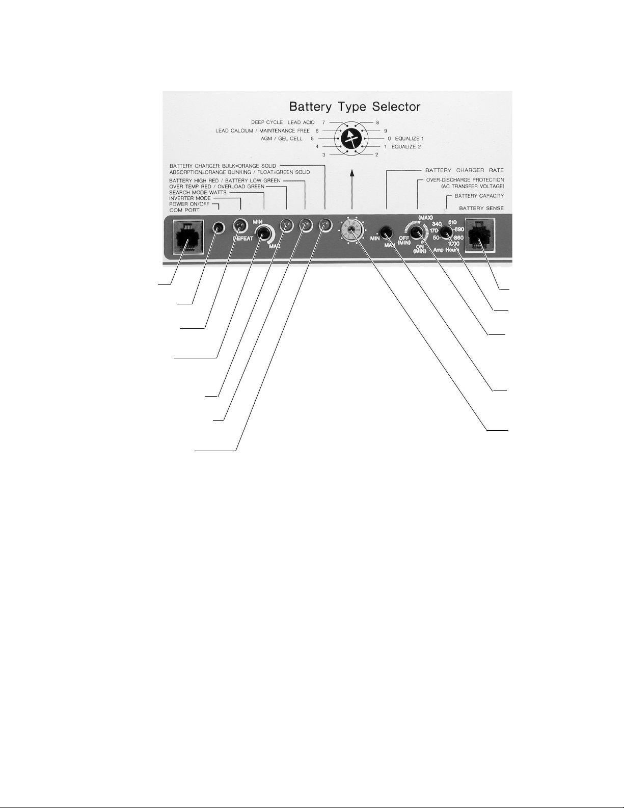
Front Panel Controls and Indicators (continued)
3.0 OPERATION
COM PORT
POWER ON/OFF
Switch
INVERTER MODE
LED
SEARCH MODE
WATTS
OVER TEMP/OVERLOAD
BATTERY HIGH RED LED
BATTERY LOW GREEN LED
BATTERY CHARGER
ORANGE/GREEN LED
Figure 33
Front Panel Controls and Indicators
BATTERY SENSE Port
The BATTERY SENSE Port is used for connecting a battery temperature sensor (BTS) to
control the charging rate based on battery temperature. The sensor should be taped onto the
side of one of the batteries. The information received in this port adjusts the chargers output
higher in cold temperatures, assuring the batteries receive a full charge, and lowers it during
warm temperatures, reducing battery gassing and providing overcharge protection.
BATTERY
TEMPERATURE
SENSE Port
BATTERY
CAPACITY
OVERDISCHARGE/
(AC
TRANSFER
VOLTAGE)
BATTERY
CHARGER
RATE
BATTERY
TYPE
Refer to the Installation section for the BTS location on the battery.
©2000 Xantrex Technology Inc.
37
Page 46
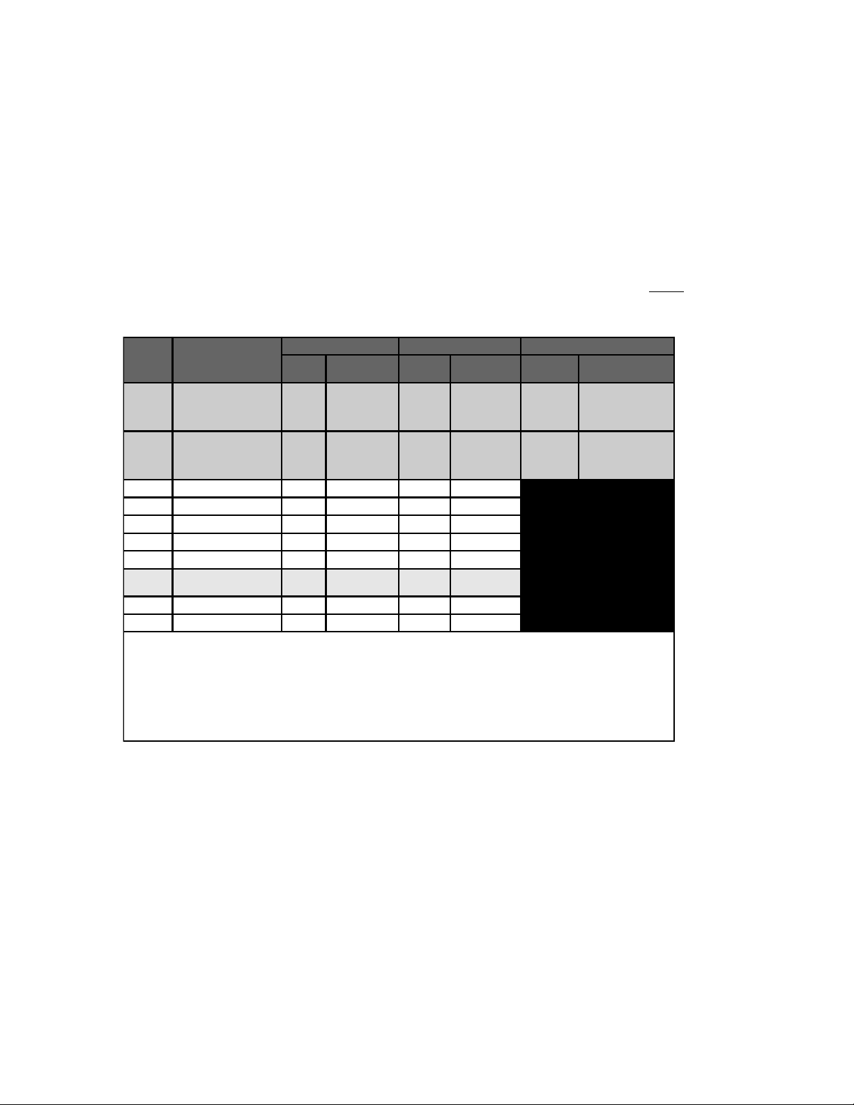
3.0 OPERATION
Front Panel Controls and Indicators (continued)
Controls
There are several controls on the inverters front panel that provide adjustments for the
battery charger, and AC output energy saving mode.
DC Controls
Battery Type Selector
The Battery Type Selector is a 10 position rotary switch used to set the inverters charger
for the proper Float and Bulk voltage levels. These levels are selected depending on the type
of batteries used. There are also 2 positions (0 and 1) which allow the batteries to be
equalized. Equalizing batteries should only be done on liquid lead acid batteries and never
on sealed batteries. Refer to the table below for the charge voltages in the various switch
positions.
Switch
Position
0 Equalize 1 13.2 *15.0 26.4 *30.0
1 Equalize 2 13.2 *15.5 26.4 *31.0
2 Deep Cell Lead Acid 2
3 Not Specifie d
4Gel Cell 213.7 14.4 27.4 28.8
5Gel Cell 1
6 PbCa–Lead Acid
7
8NiCad 1
9NiCad 214.5 16.0 29.0 32.0
NOTES:
Switch positions "0" and "1" are for monthly battery maintenance only. Return the switch to the appropriate position for the system’s batteries when
Equalize charging has completed. NEVER EQUALIZE SEALED BATTERIES! Use together with BATTERY CHARGER RATE potentiometer
(position 1) or BATTERY CAPACITY potentiometer (position 0).
Equalize voltages are displayed in the table with an asterisk (*)–switch positions "0" and "1" only.
Switch position "7" is the default value as shipped from the factory.
Always refer to the battery manufacturer's specificatio ns for Float, Bulk and Equalize (if applicable) voltages.
Description
Deep Cycle Lead Acid 1
(Default Setting)
12 Volt Mode ls 24 Volt Models Equalize
Float
Voltag e
Bulk/Eq ualiz e*
Volta ge
13.3 15.0 26.6 30.0
13.6 14.3 27.2 28.6
13.5 14.1 27.0 28.2
13.2 14.3 26.4 28.6
13.4 14.6 26.6 29.2
14.0 16.0 28.0 32.0
Float
Volta ge
Bulk/Eq ualiz e*
Volta ge
Charge
Rate
Battery
Capacity
Setting
(C/40)
Battery
Charger
Rate Setting
(manual)
Time
6 hours minimum
12 hours maximum
6 hours minimum
12 hours maximum
975-0012-014
Table 7
Battery Type Selector Switch Settings
Switch Positions
0 and 1Equalize 1 and 2
These positions are used to equalize lead acid batteries. When selected, the batteries
are held at the Bulk voltage for a minimum of 6 hours. Position 0 equalizes at a rate equal
to the battery bank capacity (in amp-hours) divided by 40. Position 1 charges at a rate set
by the BATTERY CHARGER RATE control.
2Deep Cycle Lead Acid 2
Provides an additional Float and Bulk settings for deep cycle, lead acid batteries. Refer
to the battery manufacturers recommendation for Float and Bulk settings.
3Not Specified
Provides an additional set of Bulk and Float voltages.
38 ©2000 Xantrex Technology Inc.
Page 47
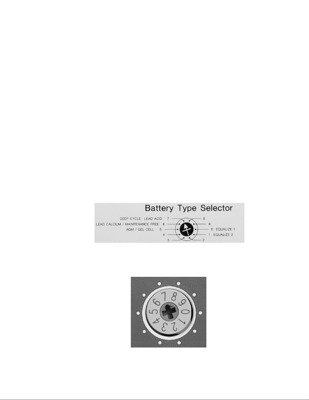
Front Panel Controls and Indicators (continued)
Switch Positions (continued)
4GEL Cell 2
Recommended for gel cell batteries that specify high float voltages. Check with the
batterys manufacturer.
5GEL Cell 1
Typical gel cell setting.
6PbCa - Lead Calcium
Use this setting for sealed type car batteries.
7Deep Cycle Lead Acid
Factory setting for typical deep cycle lead acid batteries.
8NiCad 1
Use for NiCad battery systems.
9NiCad 2
Recommended for use with nickel iron batteries.
3.0 OPERATION
©2000 Xantrex Technology Inc.
Figure 34
Battery Type Selector Graphic
Figure 35
Battery Type Selector Adjustment
39
Page 48

3.0 OPERATION
Front Panel Controls and Indicators (continued)
SEARCH MODE WATTS Potentiometer
The Search Mode Watts potentiometer adjusts the current threshold required to bring the
inverter out of search mode into full wave operation. With search mode enabled, the inverter
pulses the AC output looking for an applied load. With no load detected, the inverter goes into the
search mode to minimize energy consumption. When a load is applied, the load current is
sensed, bringing the inverter into full power operation. Disabling the threshold (setting the
potentiometer fully CCW) causes the inverter to remain ON (in full power operation) regardless of
an applied load.
To set the Search Mode Watts:
Remove the AC input source from the inverter. The inverter switches to battery operation.
Ensure all inverter supported appliances are switched OFF.
Turn the potentiometer completely CW (to MAX).
Switch on the load which will trigger the inverter to full power. This could be a lamp located in
a convenient location if the power goes out. The light may flicker as the inverter searches the
line for a load. The green INVERTER MODE LED blinks 2-3 times a second, indicating the
inverter is in the SEARCH MODE.
Slowly turn the potentiometer CCW (toward MIN) when the proper setting is found, the lamp
and INVERTER MODE LED will light steady.
Turn the lamp OFF for a moment, the inverter should switch back to the SEARCH MODE.
Turn the lamp ON, ensure the inverter comes out of the Search Mode. Adjust the
potentiometer up or down as necessary.
NOTE: The Search Mode only activates when the unit is operating in the inverter mode (from
batteries) to prevent unnecessary battery discharge when electrical power is not required. If the
inverter is supporting loads that must constantly be powered, turn the search mode OFF by setting
the potentiometer fully CCW to the DEFEAT position.
NOTE: Some loads constantly draw power even though they are switched OFF. These include: TVs
with instant-ON circuits, microwaves with digital displays, VCRs, etc. It is best to operate these
devices from another circuit or install a switch to turn these OFF completely.
NOTE: When the SEARCH MODE is used with series stacked inverters, only 120 VAC loads
connected to the master inverter will bring the unit out of the search mode. Refer to Series
Stacking in the Installation section of this manual.
INVERTER MODE LED
blinks 2-3 times/second
Lower wattage device
turns ON inverter
DEFEAT switches
SEARCH MODE OFF
Higher wattage device
turns ON inverter
Figure 36
Search Mode Sensitivity Adjustment Potentiometer
40 ©2000 Xantrex Technology Inc.
Page 49

3.0 OPERATION
Front Panel Controls and Indicators (continued)
Battery Charger Rate
The Battery Charger Rate potentiometer sets the maximum charge current supplied to the
battery bank and is also used to regulate constant current in the Bulk Charge Mode. The level
should be adjusted to provide a charge rate less than or equal to the amp-hour capacity of the
battery bank divided by a factor between 3 or 5 (5=gelled batteries and 3=lead-acid batteries).
Example:
1. Inverter DR1512 has a maximum charge rate of 70 amps.
Battery bank amp-hour capacity = 500 amp-hours using gel cell batteries.
Divide the amp-hour capacity by 5 (500/5 = 100).
Set the potentiometer to MAX (70 amps) as it is less than 100.
2. Inverter DR1512 has maximum charge rate of 70 amps.
Battery bank amp/hour capacity is 250 amp-hours using gel cell batteries.
Divide the amp-hour capacity by 5 (250/5 = 50).
Set the potentiometer to approximately 71% (50 amps).
Use the table below to find the approximate setting of the Battery Charge Rate potentiometer.
The settings do not need to be exact, but should be as close as possible to the actual value
required.
NOTE: The potentiometer does not have an arrow to indicate its position. Use a small blade
screwdriver and rotate the control completely CCW to find the start position. Rotate the
potentiometer CW to the desired position (i.e., halfway between the stops for a 50% setting).
Percent of Potentiometer Rotation
(between stops)
Model
DR1512
DR2424
DR3624
DR2412
DR1524
0%
MIN
0 amps 17.5 amps 35 amps 52.5 amps 70 amps
0 amps 30 amps 60 amps 90 amps 120 amps
0 amps 8.75 amps 17.5 amps 26.25 amps 35 amps
25% 50% 75%
100%
MAX
975-0012-011
Table 8
Approximate Charge Rate Setting/Amperage
25%
(17.5 amps)
50%
(35 amps)
71% approximately
(50 amps)
Example 2
0%
(0 amps)
Battery Charger Rate Potentiometer (DR1512 values used)
©2000 Xantrex Technology Inc.
75%
(52.5 amps)
100%
(70 amps)
Example 1
Figure 37
41
Page 50
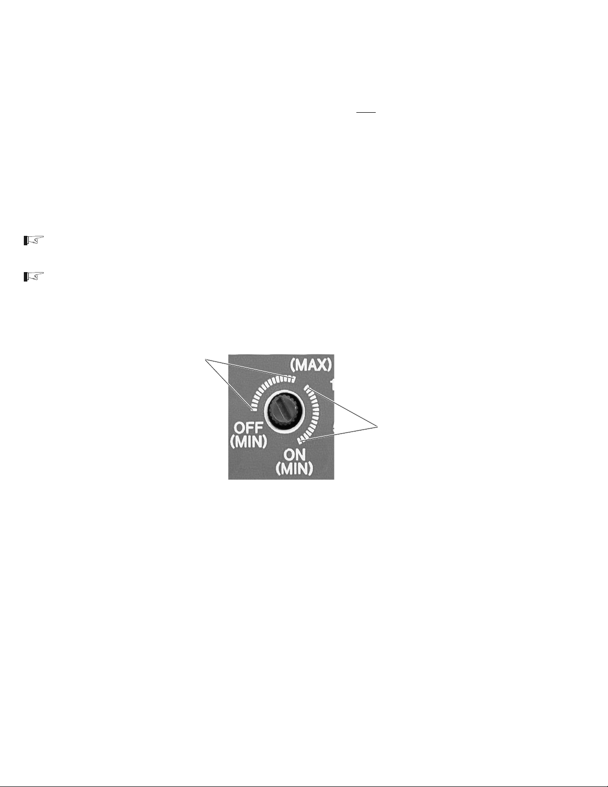
3.0 OPERATION
Front Panel Controls and Indicators (continued)
Over Discharge Protection/AC Transfer Voltage
The Over Discharge Protection/AC Transfer Voltage potentiometer performs two related
functions. When set between the 2 and 5 oclock position (right), both ODP and the AC Transfer
Voltage function simultaneously (see table on next page). When the potentiometer is set between
the 9 and 1 oclock position (left), only the AC Transfer Voltage is functional (ODP is disabled).
Over Discharge Protection (ODP)
When enabled, ODP shuts down the inverter at a specified voltage (low battery cutoff) to
protect the batteries from over discharge damage. The inverter circuitry calculates the lowest
(safe) DC voltage (leaving approximately 20% battery capacity) based on the position the
Battery Type Selector switch and the amount of current drawn by the load. Under no-load
conditions this level is typically between 11.8 and 12.0 VDC (for a 12 volt battery bank).
NOTE: The range of set points between 2 and 5 oclock also determine the low AC Transfer Voltage.
This must be considered when adjusting this potentiometer with ODP enabled (see next page).
NOTE: When ODP is disabled (set points between 9 and 1 oclock), the inverter is programmed to
shut OFF when the batteries reach approximately 8.5 VDC (1.4166 V/cell).
ODP disabled
range
ODP enabled
range
Figure 38
ODP Enabled/Disabled Positions
42 ©2000 Xantrex Technology Inc.
Page 51
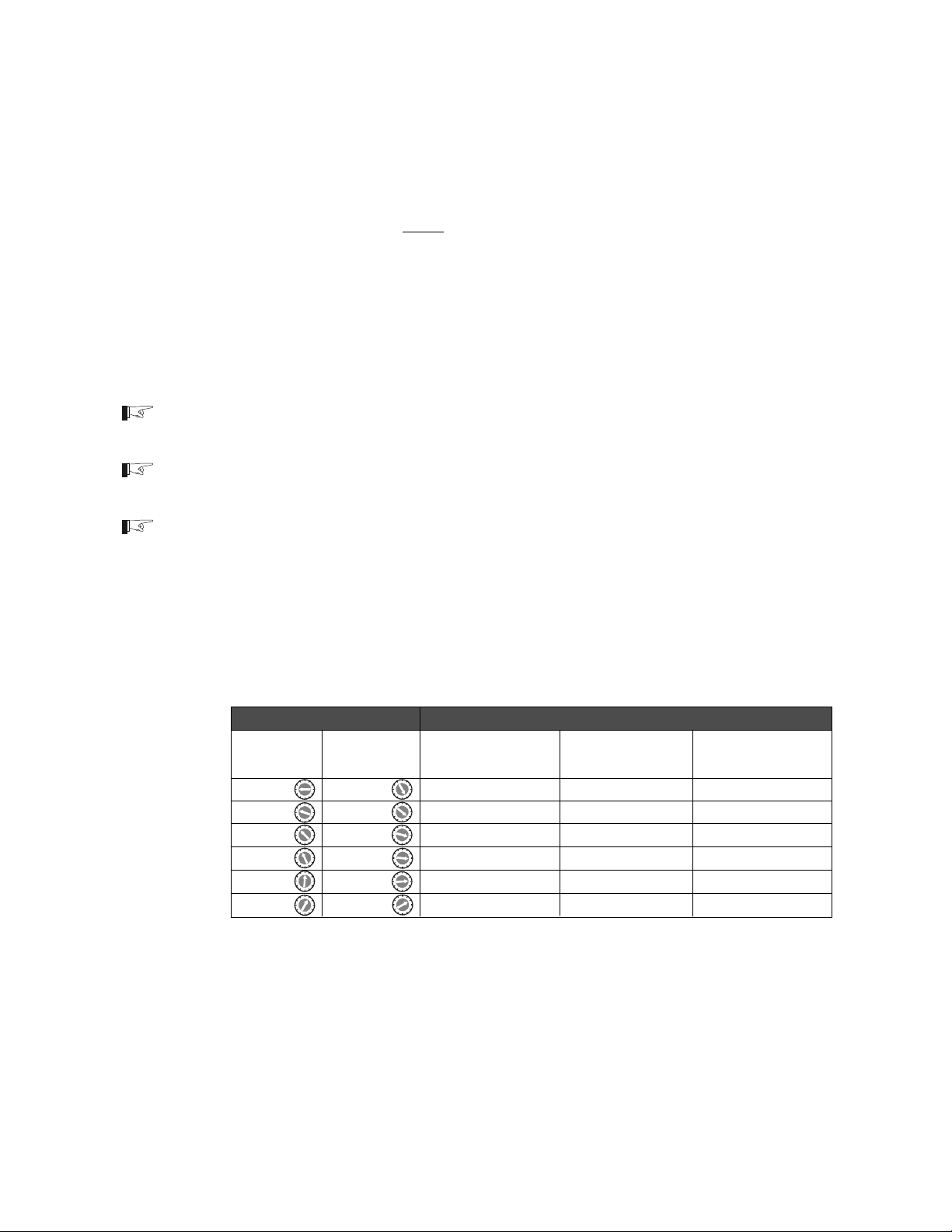
3.0 OPERATION
Front Panel Controls and Indicators (continued)
Over Discharge Protection/AC Transfer Voltage, (continued)
AC Transfer Voltage
During normal operation, the inverter supplies AC power to the applied loads through the
pass-through circuit and simultaneously charges the system batteries. Whenever the
external AC source drops below the AC Transfer Voltage (set by the potentiometer), the
inverter switches to battery power in order to maintain the connected load.
Examples (120 VAC inverter system):
The AC Transfer Voltage potentiometer is set to 9:00 oclock with ODP disabled. Whenever
the incoming AC voltage drops to 40 volts or below, the inverter will switch to battery power.
The AC Transfer Voltage potentiometer is set to 2:00 oclock with ODP enabled. Whenever
the incoming AC voltage drops to 105 volts or below, the inverter will switch to battery power.
NOTE: ODP does not affect the operation of the AC Transfer Voltage. ODP is either ON or OFF,
depending upon the position of the potentiometer.
NOTE: There are 6 settings available for the AC Transfer Voltage for both ODP OFF and ON as
shown in the Table 9 below.
NOTE: To achieve the fastest transfer time (typically less than 16 ms), set the AC Transfer Voltage
potentiometer near the 2:00 oclock position (with the ODP enabled); or, near the 1:00 oclock
position (with the ODP disabled). If a high number of nuisance transfers caused by transients on
the AC line occur, adjust the potentiometer from the maximum position toward the minimum position
(i.e., 2 oclock toward 5 oclock with ODP enabled; or 1 oclock toward 9 oclock with ODP disabled).
ODP Adjustment AC Transfer Voltage
ODP ODP 100 - 105 VAC 120 VAC 220 - 230 VAC
Disabled Enabled (-J / -K) Models Models (-W / -E) Models
9:00 5:00 36 VAC 45 VAC 90 VAC
Approximate
Approximate
Approximate
Approximate
Approximate
Approximate
Approximate
Approximate
77 VAC 85 VAC 170 VAC
81 VAC 90 VAC 180 VAC
86 VAC 95 VAC 190 VAC
90 VAC 100 VAC 200 VAC
1:00 2:00 95 VAC 105 VAC 210 VAC
Table 9
ODP/AC Transfer Voltage
©2000 Xantrex Technology Inc.
43
Page 52
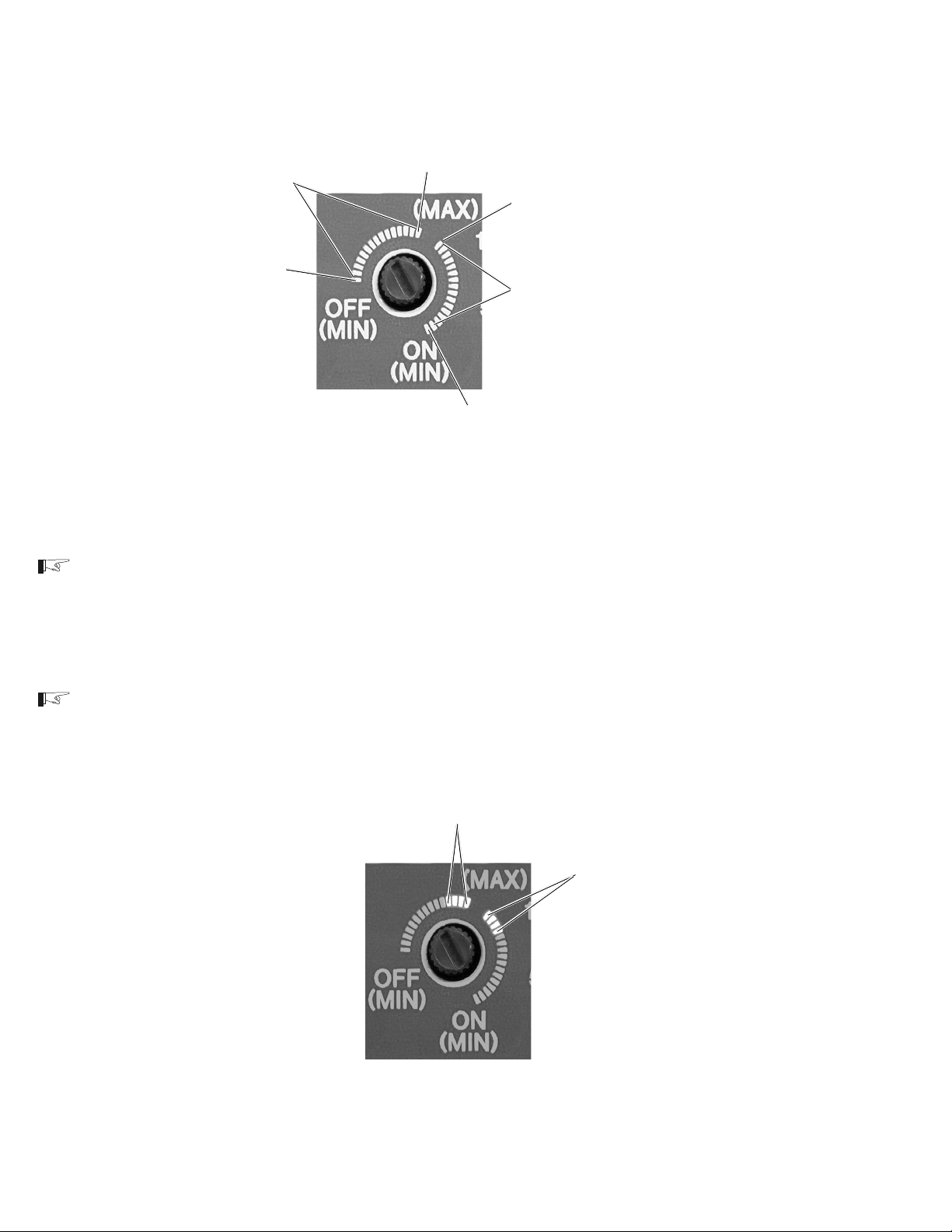
3.0 OPERATION
Front Panel Controls and Indicators (continued)
Maximum
Maximum
(105 VAC for 120 VAC models)
AC Transfer Voltage (adjustable)
with ODP Disabled
Minimum
( 45 VAC for 120 VAC models)
(105 VAC for 120 VAC models)
AC Transfer Voltage (adjustable)
with ODP Enabled
( 45 VAC for 120 VAC models)
Minimum
Figure 39
AC Transfer Voltage Potentiometer
NOTE: Most AC appliances will operate properly with an AC pass-through voltage between 95 and
105 volts. Setting the AC Transfer Voltage potentiometer between these values will allow the
incoming source voltage to drop to this level and still operate the connected appliances (load). If the
appliances do not operate properly at the lower AC utility pass-through voltage, increasing the
setting of the potentiometer (toward MAX) allows the inverter to transfer to battery power (providing
full AC output) during these periods.
NOTE: When setting the AC Transfer Voltage potentiometer for generator applications, the setting
may need to be lowered if high powered loads cause the generator voltage to momentarily drop.
Typical Setting Range for utility
applications (ODP OFF)
Typical Setting Range for
utility applications (ODP ON)
Figure 40
Typical Setting for Most Utility Applications
44 ©2000 Xantrex Technology Inc.
Page 53

3.0 OPERATION
Front Panel Controls and Indicators (continued)
Battery Capacity
The Battery Capacity potentiometer is used to set the correct charge profile for the battery
capacity (amp-hours) used with the inverter (see illustration below). The setting allows the
inverter to calculate over-discharge protection values and also the end of the Bulk/Absorption
charge mode, at which point the inverter switches to the Float mode of battery charging.
The potentiometer should be adjusted as close as possible to the actual capacity of the
battery bank for optimum charging. If the systems battery bank is larger than 1000 amp-hours,
set the potentiometer for 1K.
NOTE: Most battery manufacturers list the amp/hour rating on the battery label.
50 amp-hours
(small battery bank)
1000 amp-hours
(use for 1000 amp-hour
or larger battery banks)
Figure 41A
Battery Capacity Potentiometer
(New)
NOTE: The Battery Capacity (Amp/Hrs) potentiometer values have changed between the minimum
value of 50 Ah and 1 kAh. Please use the photo that matches your unit.
250 amp-hours
125 amp-hours
50 amp-hours
(small battery bank)
370 amp-hours
500 amp-hours
1000 amp-hours
(use for 1000 amp-hour
or larger battery banks)
©2000 Xantrex Technology Inc.
Figure 41B
Battery Capacity Potentiometer
(Old)
45
Page 54

3.0 OPERATION
Front Panel Controls and Indicators (continued)
LED Indicators
There are four LEDs on the inverters front panel, indicating inverter status, battery condition,
over temperature/overload conditions and charger status. These LEDs blink or change color
depending on the condition or function they are displaying.
INVERTER MODE
OVER TEMP/OVERLOAD
BATTERY HIGH/LOW
BATTERY CHARGER
Figure 42
LED Indicators
Inverter Mode LED - Green
The green Inverter Mode LED lights (solid) to indicate the inverter is running on batteries (full
wave operation). When the inverter is in search mode (no load applied) the LED flashes 2 to 3
times per second. During AC line operation, with AC passing directly through to the connected
load, the LED remains OFF.
Over Temp / Overload LED - Red / Green (error condition)
The Over Temp / Overload LED is a dual color, dual function indicator. When the inverters
temperature is too high for safe operation, the LED lights (red) to indicate the Over Temp
condition. When the temperature returns to a safe level, the LED turns OFF. If the condition
persists, the inverter will shut down, cool and then restart.
Whenever the current draw exceeds a value programmed into the micro-controller, the LED
lights (green) to indicate the Overload condition. The LED can remain ON for up to one hour
(before inverter shutdown) if the condition is caused by a fault in the charger circuit. When the
fault condition clears, the LED turns OFF. If the condition is caused by backfeed (connecting the
AC line to the inverters output) the LED will remain ON for approximately 10 seconds before the
inverter shuts down.
46 ©2000 Xantrex Technology Inc.
Page 55

3.0 OPERATION
Front Panel Controls and Indicators (continued)
Battery High/Battery Low LED - Red/Green (error condition)
The Battery Hi / Battery Low LED is a dual color, dual function indicator. Whenever battery
voltage exceeds a safe value, the LED lights red to indicate the condition. This value is typically
15.5 volts DC for a 12 volt system (31 volts DC for a 24 volt system). If the condition persists, the
inverter will shut down until the battery voltage returns to a safe level and then restart.
NOTE: In renewable energy applications (solar, wind, hydro, etc.) the DC charge controllers must be
set to a level below the inverters maximum input voltage or the inverter shuts OFF.
Whenever the battery voltage drops to its lowest (safe) level (approximately 20% of battery
capacity), the LED lights green to indicate the condition. If the condition persists, the inverter will
shut down until the battery voltage returns to a safe level and then restart.
NOTE: The inverter automatically restarts when the following error conditions are detected: LOW/
HIGH BATTERY, OVER TEMPERATURE, or a quick duration SHORTED OUTPUT or OVERCURRENT. The inverter shuts OFF and requires a MANUAL restart if the following conditions are
detected: a prolonged overload condition (approximately 10 seconds) or the inverters output is
connected directly to an AC power source (utility grid or generator).
Charger LED - Orange / Green
The Charger LED is a dual color, triple function indicator. When the charger is in Bulk mode,
the LED lights orange. When the charger is in Absorption mode, the LED blinks orange. When
the charger is in Float mode, the LED lights green.
NOTE: The battery charger control circuit operates from the battery voltage. If the battery voltage
falls below 7 volts, the inverter/charger will not operate. The batteries must first be recharged using
a stand-alone charger to bring the voltage up to a level where the inverter/charger can operate.
Audible Indicator (internal)
A buzzer is located on the control board as an audible alert to fault conditions such as Battery
High/Battery Low, or Overload. Steady buzzing indicates an impending inverter shut down. A
pulsing chirp indicates the inverter is temporarily off-line due to a fault condition (either within the
inverter or related to the system).
©2000 Xantrex Technology Inc.
47
Page 56

3.0 OPERATION
Front Panel Controls and Indicators (continued)
Circuit Breakers
The DR inverter/charger contains two circuit breakers located on the right-hand side of the
chassis, directly above the AC input terminal block. The pass-through AC input circuit breaker
protects the AC wiring and connected load. The charger AC input circuit breaker protects the
charger circuit. The breakers are rated for the maximum charge rate and pass-through current
allowed according to the rating of the internal relay.
Models DR15xx DR24xx DR36xx
120 VAC 30 amps 30 amps 30 amps
240 VAC 15 amps 15 amps N/A
Table 10
AC Pass-through Circuit Breakers
Models DR15xx DR24xx DR36xx
120 VAC 20 amps 30 amps 30 amps
240 VAC 8 amps 15 amps N/A
AC Pass-through
Circuit Breaker
Charger AC Input
Circuit Breaker
Table 11
Battery Charger Circuit Breakers
Figure 43
AC Pass-through and Charger AC Input Circuit Breakers
48 ©2000 Xantrex Technology Inc.
Page 57

3.0 OPERATION
Start-up
Once the inverter is properly connected to the batteries, utility (or generator) and loads (via a
sub-panel) the inverter is ready for operation. Recheck the controls (previously discussed) and
ensure they are in the proper position. Recheck all wiring and ensure it is correct.
Starting the inverter:
Apply DC power to the inverter by switching on the DC disconnect circuit breaker. The
inverter will go through a self-test and then shut OFF.
Apply AC power to the inverter by switching ON the utility circuit breaker located in the utility
service entrance.
Press the ON/OFF button once. The inverter will sound an audible chirp.
The inverter starts charging the batteries in the Bulk mode, indicated by the CHARGER LED
illuminating a solid orange.
Using a true rms AC voltmeter, check the output voltage of the inverter. This voltage can be
checked at either the AC terminal block or in the sub-panel (between the HOT and NEUTRAL
lines). The voltage should be 120 VAC (230 VAC for E models, 220 VAC for W models, or
105 VAC for J and K models).
Switch the AC disconnect circuit breaker to OFF. The inverter will go into the inverter mode (if
a sufficient load is applied to the AC output while in the search mode). The green INVERTER
MODE LED will light solid indicating the inverter is active. The voltage on the AC output of the
inverter will remain the same as above (± 5% maximum).
NOTE: If the inverter is in the SEARCH MODE (INVERTER MODE LED flashing) and a sufficient
load is not available to bring the inverter up to full voltage, turn the SEARCH MODE WATTS
potentiometer fully CCW to defeat the search function.
Reapply the AC power by switching the AC disconnect to ON. Allow the batteries to fully
recharge.
POWER ON/OFF Switch
INVERTER MODE LED
SEARCH MODE
WATTS Potentiometer
©2000 Xantrex Technology Inc.
CHARGER LED
Figure 44
Start-up Items
49
Page 58

3.0 OPERATION
Charger Mode
3-Stage Charging Process
The charging cycle uses a 3-stage charging process to maintain the batteries. Whenever
nominal AC is present at the inverters input, it passes power through to the connected load and
begins charging the batteries, indicated by the dual color BATTERY CHARGER LED.
Bulk Charge
Bulk charge is the first stage in the charging process and provides the batteries with a
controlled, constant current. A solid orange BATTERY CHARGER LED indicates bulk charge. The
bulk charge level is adjustable using the BATTERY CHARGER RATE potentiometer. Once the
battery voltage rises to the bulk voltage threshold, the charger then switches to the absorption
mode.
Absorption Charge
Absorption charge is the second stage of battery charging and provides the batteries a
controlled, constant voltage for a set period of time. A blinking orange BATTERY CHARGER LED
indicates absorption charge. During this stage the current supplied to the batteries slowly
decreases. When the current equals the programmed return amps value (battery bank capacity/
40) set with the BATTERY BANK CAPACITY potentiometer, the charger switches to the third
stagefloat.
NOTE: If there are DC loads connected to the battery, the current may never decrease to the level to
initiate the float stage. The inverter/charger incorporates a timer circuit which starts counting when
AC voltage is applied. To ensure that the charger does not stay indefinitely in the absorption charge
mode, the timer automatically switches to the float charge mode when 12 hours have elapsed.
Float Charge
Float charge, the final stage of battery charging, maintains a trickle charge to the batteries
whenever AC is present on the inverters input. A solid green BATTERY CHARGER LED
indicates float charging which reduces battery gassing, minimizes watering requirements (for
flooded batteries) and ensures the batteries are in a constant state of readiness.
A new 3-stage charging cycle is initiated after an AC source is reapplied to the inverters AC
input terminals such as after a utility outage.
BATTERY CHARGER LED
Solid Orange = Bulk
Blinking Orange = Absorption
Solid Green = Float
BATTERY CAPACITY
Figure 45
Charger Items
50 ©2000 Xantrex Technology Inc.
Page 59

3.0 OPERATION
Charger Mode (continued)
Equalize Charging
Equalize charging is a special mode of battery charging. During use, the batterys cells can
become unequal in the voltage and current they can deliver. This is due to a buildup of sulfate on
the plates as well as stratified electrolyte. Sulfate prevents the cells from receiving or delivering full
power. If the sulfate is left on the plates, it will harden, and permanently reduce the batterys
capacity. Stratification separates the heaver acid from the water, and the concentrated acid remains
at the lower portion of the plates, eventually corroding them.
Equalize charging holds the battery at the Equalize voltage for a minimum of 6 hours. This stirs
up the electrolyte, distributing the acid, and removing the sulfate from the plates. Equalizing the
batteries every month or two (depending on usage) prolongs the life of the batteries and provides
better battery performance.
CAUTION: ONLY UNSEALED OR VENTED BATTERIES SHOULD BE EQUALIZE CHARGED.
SINCE HYDROGEN AND OXYGEN GASES ARE PRODUCED WHEN EQUALIZED, PROVIDE
ADEQUATE VENTILATION AND REMOVE ALL SOURCES OF IGNITION TO PREVENT
EXPLOSION. REMOVE DC LOADS WHILE EQUALIZING AS THEY CAN BE DAMAGED BY THE
HIGHER BATTERY VOLTAGE.
Consult the battery manufacturers recommendation for equalize charging settings.
Setting the Equalize Charge
Remove all DC loads connected to the batteries.
Remove all battery vent caps.
Check the battery water level, it should be just over the top of the plates (do not overfill). Use
only distilled water for filling batteries.
NOTE: Recheck the water the level during equalize charging and refill if necessary.
Set the BATTERY TYPE SELECTOR switch to position 0 or 1 to start the equalization
charging process. A solid orange BATTERY CHARGER LED indicates equalize charge.
Position 0 equalizes the batteries at the rate of the battery bank capacity divided by 40
(C/40) at a voltage of 15 volts for 12 volt systems or 30 volts for 24 volt systems. This is
set with the BATTERY CAPACITY potentiometer.
Position 1 equalizes the batteries at the rate set with the BATTERY CHARGER RATE
CONTROL at a voltage of 15.5 volts for 12 volt systems or 31 volts for 24 volt systems.
When the voltage condition is met and 6 hours have elapsed, the charger will switch to the float
mode. If the condition is not met (i.e., the current draw is above the rate set with the BATTERY
CAPACITY potentiometer (position 0) or BATTERY CHARGER RATE potentiometer (position 1)),
the charger will continue until the condition is met, or for a maximum of 12 hours. At this point the
charger switches to float at the equalize 1 or 2 voltage setting (see table on the next page).
Reset the BATTERY TYPE SELECTOR potentiometer to the appropriate setting for the
systems batteries when the Equalize charge has completed.
NOTE: Refer to the Battery section of the Appendix for additional battery maintenance information.
©2000 Xantrex Technology Inc.
51
Page 60
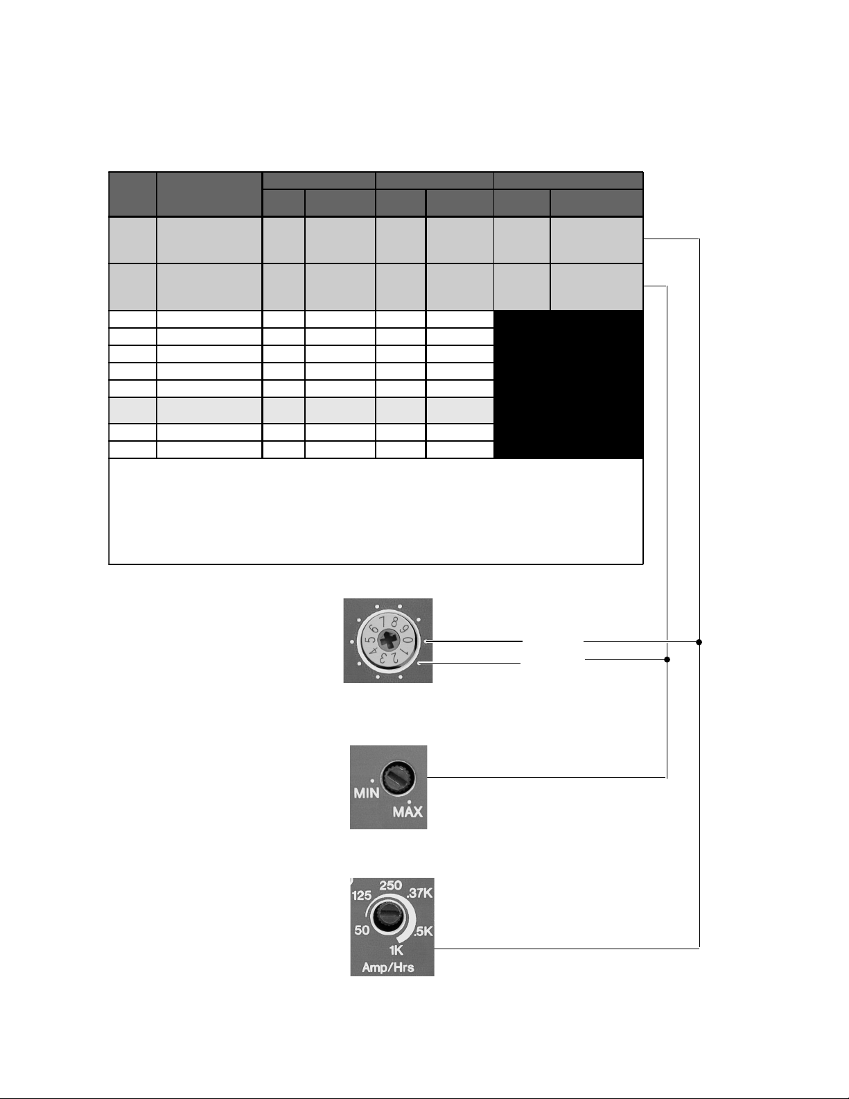
3.0 OPERATION
Charger Mode (continued)
Switch
Position
0 Equ alize 1 13.2 *15.0 26.4 *30.0
1 Equalize 2 13.2 *15.5 26.4 *31.0
2 Deep Cell Lead Acid 2
3 Not Specified
4 Gel Cell 2
5Gel Cell 1
6PbCa–Lead Acid
7
8NiCad 1
9NiCad 2
NOTES:
Switch positions "0" and "1" are for monthly battery maintenance only. Return the switch to the appropriate position for the system’s batteries when
Equalize charging has completed. NEVER EQUALIZE SEALED BATTERIES! Use together with BATTERY CHARGER RATE potentiometer
(position 1) or BATTERY CAPACITY potentiometer (position 0).
Equalize voltages are displaye d in the table with an asterisk (*)–switch positions "0" and "1" only.
Switch position "7" is the default value as shipped from the factory.
Always refer to the battery manufacturer's specifications for Float, Bulk and Equalize (if applicable) voltages.
Description
Deep Cycle Lead Acid 1
(Default Setting)
12 Volt Models 24 Volt Models Equalize
Float
Vol tage
Bu lk/Equa lize*
Vol tag e
13.3 15.0 26.6 30.0
13.6 14.3 27.2 28.6
13.7 14.4 27.4 28.8
13.5 14.1 27.0 28.2
13.2 14.3 26.4 28.6
13.4 14.6 26.6 29.2
14.0 16.0 28.0 32.0
14.5 16.0 29.0 32.0
Float
Voltage
Bulk /Equa lize*
Voltage
Charge
Rate
Battery
Capacity
Setting
(C/40)
Battery
Charger
Rate Setting
(man ual )
Time
6 hours minimum
12 hours maximum
6 hours minimum
12 hours maximum
975-0012 -014
Equalize 1
Equalize 2
Figure 46
Equalize Positions on BATTERY TYPE SELECTOR Switch
Figure 47
Equalize 1 BATTERY CHARGER RATE Potentiometer (position 1)
Figure 48
Equalize 2 BATTERY CAPACITY Potentiometer (position 0)
52 ©2000 Xantrex Technology Inc.
Page 61

4.0 TROUBLESHOOTING
Troubleshooting
Error Condition Possible Cause Solution
Battery HIGH LED (red) is ON,
buzzer is ON.
Battery LOW LED (green) is ON,
buzzer is ON.
OVERTEMP LED (red) is ON,
buzzer is ON.
The battery voltage is above the
high battery voltage input tolerance.
Battery over-discharge circuit is ON.
Battery voltage is below the low
battery discharge tolerance.
AC input voltage may be too high.
The inverter is powering a large
load for a long time.
Ambient temperature may be high
or inverter cooling fan may have
failed.
Use a DVM and measure the voltage at the
inverter’s DC input terminals. Ensure the DC
source is regulated below the High Battery
Cutout voltage.
Charge batteries or disable the OVERDISCHARGE PROTECTION.
Use a DVM and measure the voltage at the
inverter’s DC input terminals.
Check for an external DC load on the
batteries.
Check the condition of the batteries and
recharge if necessary.
Check the AC INPUT circuit breaker and reset
if necessary.
Use an AC DVM and measure the input
voltatge.
Remove excessive loads.
Let inverter cool down before restarting.
Check inverter’s cooling fan.
OVERLOAD LED (green):
- turns ON after the i nverter was
running large loads.
- turns ON when the inverter is
OFF.
- flickers for 5–10 seconds, then
turns ON. Loud hum when an AC
source is connected to the
inverter.
- turns ON and the inverter clicks
ON and OFF every 40 seconds.
- turns ON when charging.
INVERTER MODE LED:
- turns ON with no AC output.
- is flashing and no AC output.
Air-vents blocked.
Excessive load on the AC output.
Indicates the AC source is wired
directly to the inverter's output.
Indicates the AC source is wired
directly to the inverter's output.
Indicates the inverter's output is
wired to its input.
Charging circuit may be damaged.
AC source voltage is okay on
inverter's input. No AC output.
The load is too small for the search
mode to detect.
Check for obstructions in air-vents. Clean if
nec ess ary.
Reduce the AC load.
Check input and output wiring.
Check input and output wiring.
Check input and output wiring.
Have inverter/charger serviced.
Check for open AC output breakers or fuses.
Check AC wiring connections.
Have unit serviced.
Reduce or defeat the AC search watts setting.
Increase the AC load.
©2000 Xantrex Technology Inc.
975-0012-015-A
53
Page 62

4.0 TROUBLESHOOTING
Error Condition Possible Cause Solution
Troubleshooting
No AC output and no warning
LEDs are ON.
AC output is low and the inverter
turns loads ON and OFF.
AC output is low. Loose or corroded battery
AC output voltage is low. Measuring AC output with incorrect
CHARGER LED:
- indicates charging, but no
charge is going to the batteries.
- is ON, but there is no output
power.
Battery voltage at the inverter
terminals is too high or low.
Low battery. Check the condition of the batteries and
connections.
Loose AC output connections.
type of meter.
AC output voltage low using a true
rms reading meter or DVM.
Circuit breaker on the side of the
inverter is open.
No AC voltage on inverter’s AC
terminal block.
Good AC voltage on inverter’s AC
terminal block.
Check the battery voltage, fuses or breakers,
and cable connections.
recharge if possible.
Replace the batteries.
Check and clean all DC connections.
Check all AC output connections.
Measure AC output voltage with a true rms
reading meter or DVM.
Have unit serviced.
Reset the AC CHARGER circuit breaker on
the side of the unit.
Check "AC PASS-THRU" circuit breaker on
the side of the inverter.
Check for open AC output breakers or fuses
and AC wiring connections.
Charger is inoperative or
supplying a low charge rate.
AC lights flicker while charging. Generator is unstable and charger
Charger turns OFF while charging
from a generator.
AC voltage has dropped out-of-
tolerance.
Charger controls are improperly set.
Low peak AC input voltage (169
required for full charger
VAC
p
output).
AC current supplied from generator
is too low.
Loose or corroded battery
connections.
Loose AC output connections.
Generator is unstable - charger is
losing synchronization.
is losing synchronizati on.
High peak AC input voltages from
the generator.
Check the AC voltage for proper voltage and
frequency (depending upon model).
Refer to the section on adjusting the
"CHARGER RATE."
Use larger generator (increasing AC
voltage/RPM’s may help).
Reduce charge amps setting or reduce pass-
through loads.
Check and clean all DC connections.
Check all AC output wiring connections.
Turn BATTERY CHARGER RATE
potentiometer down to less than halfway until
problem is gone.
Turn BATTERY CHARGER RATE
potentiometer down to less than halfway until
problem is gone.
Load the generator down with a heavy load.
Turn the generator output voltage down.
54
975-0012-015B
©2000 Xantrex Technology Inc.
Page 63

5.0 APPENDIX
Batteries
Batteries are available in different sizes, types, amp-hours, voltages and chemistries. It is
important the correct battery is chosen in designing a battery bank for your application.
Selection of a Battery Type
There are two principal types of batteries: starting and deep-cycle (with several different types of
chemistries). Batteries can be either sealed or non-sealed (vented).
The battery types recommended for use in an inverter system are: Flooded Lead Acid (FLA),
Sealed Gel Cells (GEL), Sealed Absorbed Glass Mat (AGM); and alkaline types Nickel-iron (NiFe)
and Nickel-Cadmium (NiCad). DO NOT use automotive (starting) batteriesthey are designed to
provide high starting current for short periods of time.
Flooded Lead Acid (FLA)
This type of battery is designed to be deep cycled before being recharged, making it suitable for
inverter applications. Flooded batteries require periodic maintenance consisting mainly of adding
distilled water to the cells, checking battery cable connectors for tightness and keeping the terminals
clean. Examples of flooded batteries include:
RV and Marine
Popular in small systems
Often referred to as Group 24 or Group 27 batteries
Designed for limited cycling
Do not last as long as the other true deep cycle batteries
Typically rated at 12 volts (80 to 100 amp-hours)
Golf Cart
Popular for smaller off-grid home systems
Many medium sized inverter systems use L16 batteries
Rugged, long lasting
Typically rated at 6 volts (220 to 350 amp-hours)
Industrial (electric forklift)
Popular in large inverter systems
Extremely rugged - lasts up to 10 years or more in an inverter system
Typically 2 volt cells (1,000 amp-hours or more)
Sealed Batteries (GEL and AGM)
Both gel and AGM batteries are virtually maintenance free, making them ideal for inverter
applications. Since the batteries are completely sealed, they can be mounted in almost any position.
The only disadvantages, compared to flooded batteries, are a higher initial cost and greater
susceptibility to damage from changes in temperature during charging.
Gel Cell
Gelled electrolyte instead of liquid
Long life (up to 1500 cycles, typical)
Low self-discharge
Absorbed Glass Mat
Electrolyte is contained in glass-fiber mats between battery plates
Similar to gel cells in characteristics
Good low temperature performance
CAUTION: IF USING SEALED OF BATTERIES, ENSURE THE BATTERY CHARGER IS SET TO
THE APPROPRIATE SETTINGS OR BATTERY DAMAGE WILL RESULT.
©2000 Xantrex Technology Inc.
55
Page 64

5.0 APPENDIX
Selection of a Battery Type (continued)
NiCad and NiFe Batteries
Trace inverters and battery chargers are optimized for use with lead-acid batteries having a
nominal 2.0 volts per cell (i.e., 6 cells for a 12 volt system, 12 cells for a 24 volt system and 24 cells
for a 48 volt system). Alkaline batteries, such as NiCads and NiFe types, have a nominal cell voltage
of 1.2 volts per cell. The number of cells required in a battery bank for alkaline batteries must be
adjusted for a 12, 24 and 48 volt system (i.e., 10 cells for a 12 volt system, 20 cells for a 24 volt
system and 40 cells for a 48 volt system).
Alkaline batteries require a higher charge voltage to fully recharge and drop to a lower voltage
during discharge compared to a similarly sized lead acid type battery.
Another option for 24 volt (only) alkaline battery banks is to use only 19 cells instead of 20. This
allows the battery charger to operate closer to the settings used for lead-acid batteries. However,
the battery voltage will drop to as low as 18 volts when discharging the batteries.
Consult the battery manufacturer or supplier regarding system requirements and battery charger
settings for alkaline type batteries.
56 ©2000 Xantrex Technology Inc.
Page 65

5.0 APPENDIX
Battery Bank Sizing
The battery banks size determines the length of time the inverter can continue to supply AC
output power during a utility outage. The larger the bank, the longer the inverter can run. An
undersized battery bank results in reduced battery life and short inverter run times.
In general, the battery bank should be designed so the batteries do not discharge more than
50% of their capacity on a regular basis. Discharging up to 80% is acceptable on a limited basis
such as a prolonged utility outage. Totally discharging a battery results in permanent damage and
reduced battery life.
For stand-alone applications, design a battery bank that can power the loads for 35 days
without requiring recharging. To duplicate the conditions on sun-less days or windless periods, the
power supplied from other sources (i.e., solar, wind, hydro, etc.) is not included in this calculation.
This is often referred to as the number of days of autonomy. If the system is a hybrid, with daily
generator run periods, the battery bank size can be smaller.
Estimating Battery Requirements
To determine the proper battery bank size, it is necessary to compute the number of amp-hours
that are required between charging cycles. When the required amp-hours are known, size the
batteries at twice this amount to ensure the batteries are not regularly over-discharged.
To compute the amp-hour requirements, the amp-hour ratings of each appliance powered by the
inverter must be added together. Use the figures from the nameplate label on the appliances, then
use the formula WATTS = VOLTS x AMPS. Then divide the calculated wattage of the load by the
system battery voltage to determine the amperage the load will draw from the batteries.
(AC current) x (AC voltage)/(battery voltage) = DC amps.
Example:
Nameplate label specifies 6 amps at 120 VAC.
The system battery voltage is 24 volts DC.
First determine the wattage by using the formula: WATTS= VOLTS x AMPS = 120 x 6 =720
watts.
Then divide the wattage by the system battery voltage to determine the DC amperage.
720/24 = 30 amps DC amps.
If the AC wattage is specified on the nameplate label, the battery amperage will be:
(watts)/(battery voltage) = DC amps (720/24 = 30 DC amps).
Multiply the amperage by the number of hours the load will operate to roughly calculate amphours. Double this figure to reach the 50% battery capacity level.
Refer to the example and work sheet on the following pages as a guide to determine the battery
banks amp-hour requirements.
NOTE: Motors typically require 36 times their running current when starting. Check the
manufacturers data sheets for their starting current requirements. If large motors will be started from
the inverter, increase the battery bank size to allow for the higher start-up current.
©2000 Xantrex Technology Inc.
57
Page 66

5.0 APPENDIX
Battery Bank Sizing (continued)
Example
Complete the following steps to calculate the battery bank capacity requirements. Use the blank
table on the next page to enter the values for your system. An example table is shown below.
Step 1 Step 2 Step 3 Step 4
AC Applia nce
Microwave 600 0.5 7 300
Lights (x 4) 40 6 7 240
Hair Dryer 750 0.25 3 81
Television 100 4 7 400
Washer 375 1 2 107
Refrigerator* 480/3 = 160 24 7 3840
Vacuum Cleaner 1200 1 1 171
Applian ce
Running
Watts
(x) Hours Used
Each Day
(x) Days Used
Each Week
(÷ 7 =) Average Daily
Watt-Hours R equired
Total Daily Watt-Hou rs
Required
5,139 15,417 30,834 37,001 1,542
Autonomy
Battery Siz e
Rough Battery Size
(Watt-Hours)
Safe Ba ttery Size
(Watt-Hours)
Safe Battery Size
(Amp-H ours)
975-0012-016
* Refrigerators and ice-makers typically run only about 1/3 of the time, therefore the running wattage
is 1/3 of the total wattage of the appliance. Divide the total wattage of the appliance by 3 and enter
it in Step 2.
Step 1 Determine the loads the inverter will power and list them in the Step 1 column.
Step 2 Enter the running wattage of each appliance in the Step 2 column.
Step 3 Determine the number of hours (or fraction of hours) the appliance is used each day.
Enter this figure in the Step 3 column.
Step 4 Determine the number of days the appliance will be used during the week. Enter this
figure in the Step 4 column.
Step 5 Divide the number (entered into each row of the Step 4 column) by 7 to obtain the
AVERAGE DAILY WATT-HOURS REQUIRED figure. Enter these figures in the Step 5
column.
Step 6 Add all the figures entered into the AVERAGE DAILY WATT-HOURS REQUIRED (Step 5)
column and enter this number into the TOTAL DAILY WATT-HOURS REQUIRED (Step 6)
column in the second table.
Step 7 Multiply the TOTAL DAILY WATT-HOURS REQUIRED (Step 6) figure by the number of
days of autonomy (days between recharging expected, usually between 1 to 5. The
examples use 3). Enter this figure into the AUTONOMY BATTERY SIZE (Step 7) column.
58 ©2000 Xantrex Technology Inc.
Page 67
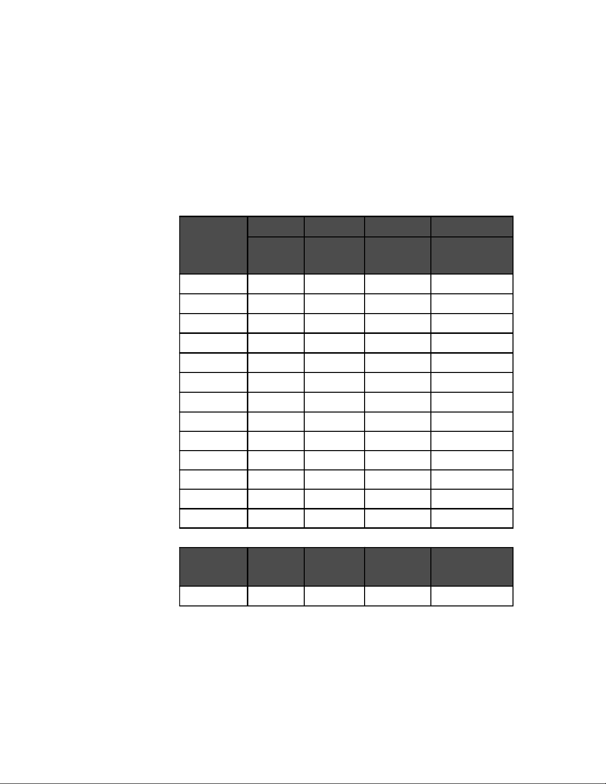
5.0 APPENDIX
Step 8 Multiply the AUTONOMY BATTERY SIZE (Step 7) figure by 2 to provide a 50%
maximum battery discharge level. Enter this figure in the ROUGH BATTERY SIZE
(WATT-HOURS) (Step 8) column.
Step 9 Multiply the ROUGH BATTERY SIZE (WATT-HOURS) figure (Step 8) by 1.2 and enter
this figure in the SAFE BATTERY SIZE (WATT-HOURS) (Step 9) column. This figure
allows for an efficiency of 80%.
Step 10 Divide the SAFE BATTERY SIZE (WATT-HOURS) (Step 9) figure by the DC system
voltage (i.e., 12, 24 or 48 volts). Enter this number in the SAFE BATTERY SIZE (AMPHOURS) (Step 10) column. Use this figure to determine the number of batteries
required to reach the amp-hour rating.
Step 1
AC Appliance
Step 2 Step3 Step 4 Step 5
Appliance
Running
Watts
(x) Ho urs Us ed
Each Day
(x) Days Used
Each Week
(÷ 7 =) Average Daily
Watt-Hours Required
Step 6
Total Da ily Watt-Hou rs
Required
©2000 Xantrex Technology Inc.
Step 7
Autonomy
Battery Siz e
Step 8
Rough Battery Size
(Watt-Hours)
Step 9
Safe Battery Size
(Watt-Hours)
Step 10
Safe Battery Size
(Amp-Hours)
975-0012-017
59
Page 68

5.0 APPENDIX
Typical Appliance Wattages
The following chart lists some common appliances and their estimated wattage. These are only
rough estimates and not intended as a replacement for the actual label ratings found on the
appliances.
Typical Appliance Wattage
Appliance Watts Appliance Watts
Fluorescent type light 10 Blender 400
Computer 200-300 Toaster 1000
Microwave (compact) 600-800 Hot Plate 1800
Microwave (full size) 1500 Washer/Dryer 375-1000
Stereo or VCR 50 3/8" Drill 500
Color TV (19") 150 Hair Dryer or Iron 1000
*Refrigerator (3 cu ft) 180 Vacuum Cleaner 1200
*Refrigerator (12 cu ft) 480 Coffee Maker 1200
* Refrigerators and icemakers typically run only 1/3 of the time, therefore,
the running watta ge is 1/3 o r the total wattag e of the ap plia nce .
975-0012-018
Table 12
Typical Appliance Wattage
60 ©2000 Xantrex Technology Inc.
Page 69

5.0 APPENDIX
Battery Care and Maintenance
To get the best performance from an inverter system, the batteries must be properly set up and
maintained. This includes setting the proper voltages for Bulk and Float charging. Monthly, the
batteries should be Equalize charged (vented batteries only) and the water level checked and
maintained (see Cautions below). In addition, the battery terminals should be inspected, cleaned
and re-torqued if necessary.
Neglecting any of these items may result in poor inverter performance and greatly reduced
battery life.
Charge Rate
The maximum safe charge rate is related to the size and type of the batteries. Standard
vented lead acid batteries (with removable caps) can be charged at a high rate, equal to their
capacity. Small batteries may require a lower charge rate. Check with your battery manufacturer
for the proper battery charging rate for the batteries used in the system.
Bulk Voltage
This is the maximum voltage the batteries will be charged to during a normal charge cycle.
Gel cell batteries are set to a lower value and non-sealed batteries are set to a higher voltage
setting.
Float Voltage
The Float voltage is set lower than the Bulk voltage and provides a maintenance charge on
the batteries to keep them in a ready state.
Temperature Compensation
For optimal battery charging, the Bulk and Float charge rate should be adjusted according to
the temperature of the battery. This can be accomplished automatically by using a Battery
Temperature Sensor (BTS). The sensor attaches directly to the side of one of the batteries in the
bank and provides precise battery temperature information.
Equalization Charging
Every month or two the batteries should be Equalize charged. This helps to remove sulfate
buildup on the battery plates and balances the charge of individual cells. Batteries that are not
equalized charged can be damaged by sulfate buildup, thus sealing off a percentage of the
plates and reducing battery capacity.
Equalize charging also produces gassing which stirs up the electrolyte mixture and helps
distribute the acid more evenly. Batteries that are not equalize charged may have the sulfuric acid
accumulate at the bottom of the battery, potentially damaging the plates. At the same time, the
electrolyte at the top of the battery gets watery. This is call stratification.
CAUTION: BECAUSE A HIGHER VOLTAGE IS USED TO EQUALIZE CHARGE THE BATTERIES,
ANY DC LOADS MUST BE DISCONNECTED BEFORE AN EQUALIZATION CHARGE IS
STARTED.
CAUTION: EQUALIZATION SHOULD BE DONE FOR STANDARD ELECTROLYTE VENTED
BATTERIES ONLY. SEALED OR GEL CELL BATTERIES SHOULD NOT BE EQUALIZE
CHARGED. CONSULT YOUR BATTERY SUPPLIER FOR DETAILS ON EQUALIZE CHARGING
FOR THE BATTERY TYPE IN YOUR SYSTEM.
©2000 Xantrex Technology Inc.
61
Page 70

5.0 APPENDIX
Battery Care and Maintenance (continued)
Replenish Water Levels
Liquid Lead-Acid batteries require periodic water refills in each battery cell. Only distilled
water should be used in a battery as tap or mineral water may contain contaminates which will
upset the battery chemistry and may damage the battery.
When filling the battery, clean the surface first to prevent dirt from entering the cell. Fill the
cell to just above the plates or to the bottom of the internal collar inside the battery. Never fill the
cells to the top or acid will leak out during charging.
Check the water level in the batteries frequently when performing an equalize charge and
add water if necessary. Always follow the safety steps covered in the front of the manual.
Clean Battery Cables and Posts
WARNING: BEFORE ATTEMPTING TO CLEAN THE BATTERY POSTS, TURN OFF THE DC
CIRCUIT BREAKER. USE ONLY INSULATED TOOLS AND REMOVE ALL JEWELRY.
Battery posts must be clean to reduce the resistance between the battery post and cable
connection. A buildup of dirt or oxidation may eventually lead to the cable terminal overheating
during periods of high current draw.
Use a stiff wire brush and remove all dirt and corrosion from the battery terminals and cables.
Use an alkaline solution of baking soda and water to clean the terminals and neutralize any
battery acid on the terminals or cable lugs.
CAUTION: NEVER LET A BAKING SODA SOLUTION GET INTO THE BATTERY AS IT WILL
NEUTRALIZE THE ACID RESULTING IN PERMANENT DAMAGE .
Torque Battery Connections
After the terminals are clean, reassemble the cable to the battery terminal and torque the
connections to the battery manufacturers recommendations.
Coat the battery terminals with an antioxidant compound.
62 ©2000 Xantrex Technology Inc.
Page 71

5.0 APPENDIX
Battery Care and Maintenance (continued)
Check Batterys State of Charge
The batterys state of charge should be checked monthly and only when the battery is not
powering heavy loads or is being actively charged. If the batteries are readily accessible,
measure the voltage across the individual battery terminals. There should be less than a 0.2 volt
difference between each battery. To determine the individual cell voltage, divide the voltage by
the number of cells in the battery (i.e., 12.6 V divided by 6 cells = 2.1 volts per cell). If a greater
difference is measured, the batteries may need to be equalized (liquid lead-acid types only) or
replaced. All batteries in the bank should measure the same voltage (this is not an accurate
measurement for cross-tied batteries as each battery is in parallel with another battery making
individual battery measurements impossible).
The voltage should match the following table for the entire battery bank output. These values
indicate the overall batterys state of charge for the entire bank. Individual cell voltages (if
available) are also shown as a percentage of charge.
The values given are for a temperature of 77 °F (25 °C). Cooler temperatures produce lower
voltage measurements.
Percent of
Full Charge
System Voltage
12 V 24 V 48 V
Individual Cell
100% 12.7 25.4 50.8 2.12
90% 12.6 25.2 50.4 2.10
80% 12.5 25.0 50.0 2.08
70% 12.3 24.6 49.2 2.05
60% 12.2 24.4 48.8 2.03
50% 12.1 24.2 48.4 2.02
40% 12.0 24.0 48.0 2.00
30% 11.8 23.6 47.2 1.97
20% 11.7 23.4 46.8 1.95
10% 11.6 23.2 46.4 1.93
0% <
11.6 < 23.2 < 46.4 < 1.93
Voltage
975-0012-019
©2000 Xantrex Technology Inc.
Table 13
Battery State of Charge
63
Page 72

5.0 APPENDIX
Problem Loads
The inverter can drive most loads, however, there are special conditions that can cause a load
to behave differently than expected. The following describes some of the common problems
encountered when using an inverter.
Ceiling Fans
Most large diameter, slow turning fans run correctly, but generate more noise than when
connected to utility power. High speed fans tend to operate normally.
Cell Phones
Some cellular telephones experience interference in the form of a clicking sound.
Computers and Sensitive Electronics
Some computers and sophisticated electronics have power supplies that do not present a
load until correct line voltage is available. When this occurs, each unit waits for the other to begin.
This can usually be solved by plugging in an additional load (such as a lamp) to bring the inverter
out of its search mode. Also, when using a computer, avoid starting large loads.
Consumer Electronics
AM radios tend to pick up inverter noise, especially on the lower half of their band.
Inexpensive tape recorders are likely to experience noise as well. When using sensitive
electronic devices, avoid starting large loads.
Clocks
The inverters crystal controlled oscillator keeps the frequency accurate to within a few
seconds a day; however, external loads in the system may alter the inverters output waveform
causing clocks to run at different speeds. There may be periods where clocks keep time and then
mysteriously do not. This is because most clocks do not draw enough power to trigger the load
sensing circuit. In order to operate, especially with no other loads present, the inverters load
sensing circuit will have to be defeated. Refer to the Operation/Search Mode Watts.
Decreasing Loads
If the amount of power a load draws decreases after it has been switched on (such as with a
small motor) and its current draw becomes less than the load sensing threshold, it will be turned
alternately ON and OFF by the inverter. This can usually be solved by plugging in an additional
load (such as a lamp).
Dimmer Switches
Most dimmer switches lose their ability to dim the lights when used with an inverter and
operate only in the fully ON or OFF position. Newer, microprocessor controlled dimmers tend to
work better in inverter applications.
64 ©2000 Xantrex Technology Inc.
Page 73

5.0 APPENDIX
Problem Loads (continued)
Fluorescent Lights
Some devices cannot be detected by the inverters load sensor and will not operate. Small
fluorescent lights are the most common example. This can usually be solved by plugging in an
additional load. Also, try turning the lamps AC plug over.
Heavy Loads
If the battery bank cannot deliver the necessary amperage to drive a heavy load, the inverter
will shut OFF. The battery voltage will then slowly rise back above the low voltage threshold
causing the inverter to resume operation. As soon as the heavy load draws the batteries down,
the cycle will continue unless the load is reduced or an additional source of power is added.
Microwave Ovens
Microwave ovens are sensitive to peak output voltages. The higher the voltage, the faster
they cook. Since the inverters peak output voltage is dependent upon battery voltage and load
size, the microwaves cook time may need to be increased.
Printers
Most inkjet type printers work well in inverter applications. Laser printers, however, require
high current for their fusing circuit and are not recommended for use with an inverter.
Rechargeable Devices
When first using a rechargeable device, monitor its temperature for 10 minutes to ensure it
does not become abnormally hot. Excessive heat will indicate that it is incompatible with the
inverter.
Undersized Loads
If the power consumed by a device is less than the inverters search mode circuitry threshold,
it will not run. This can usually be solved by plugging in an additional load such as a 100 watt
light bulb.
©2000 Xantrex Technology Inc.
65
Page 74

5.0 APPENDIX
Multiwire Branch Circuits
A potential safety problem exists when installing stand-alone 120 VAC inverters into existing
120/240 VAC wired panels where multiwire branch circuit wiring methods were used.
Multiwire branch circuits are wired differently from home run type wiring (Figure 49) in that only
one neutral wire is used to provide the neutral-return path for each circuit connected to both phases
of the AC grid. This method has been employed by electricians in recent years to keep construction
costs down by saving copper and labor costs involved in running separate romex for each circuit.
Under normal conditions, this technique is quite safe and meets code requirements. When used
as originally installed, the current for each circuit is 180° out-of-phase with each other, so the neutral
wire never receives more current than it was designed to handle as the current from each circuit
subtracts (or cancels outleaving only the difference current between the two circuits). Refer to
Figure 50.
A safety problem occurs when a stand-alone 120 VAC inverter is installed to power these
circuits, causing the one neutral wire to now carry the in-phase currents for both circuits. Since the
current is in-phase, the two circuits
neutral return wire! Refer to Figure 51. The branch circuit breakers do not protect the neutral wire
from overload under this condition. This excess current will overheat the neutral wire, potentially
creating a fire hazard.
240 VAC
from Grid
add instead of subtract, potentially doubling the current flow in the
Load Center
L2
L1
Neutral
25 A
25 A
Ground
25 A
Breaker
Black–Hot
White–Neutral
White–Neutral
Bare–Ground
Bare–Ground
25 A
Breaker
Black–Hot
25 A
120 VAC
25 A
120 VAC
062949-001
Figure 49
Conventional Home-run Type Wiring
Load Center
Ground
10 A
Single White–Neutral
25 A
Breaker
(Ganged)
Black–Hot
Bare–Ground
25 A
Breaker
(Ganged)
Red–Hot
15 A
120 VAC
25 A
25 A
120 VAC
Bare–Ground
Splice
White–Neutral
Splice
062949-002a
240 VAC
from Grid
The out-of-phase
currents subtract
at this point
L2
L1
Neutral
Load Center
Ground
Single White–Neutral
0 A
25 A
Breaker
(Ganged)
Black–Hot
Bare–Ground
25 A
Breaker
(Ganged)
Red–Hot
25 A
120 VAC
25 A
25 A
120 VAC
Bare–Ground
Splice
White–Neutral
Splice
062949-002
240 VAC
from Grid
When unbal anced
current f lows through
each leg, only the
differenc e
flows throug h the
neutral return wire.
L2
L1
current
Neutral
Figure 50
Multiwire Branch Circuit Wiring and Current Flow
66 ©2000 Xantrex Technology Inc.
Page 75

Multiwire Branch Circuits (continued)
Load Center
120 VAC
Inverter
(or generator)
Neutral
Ground
Breaker
(Ganged)
25 A
25 A
Breaker
(Ganged)
Red–Hot
5.0 APPENDIX
25 A
25 A
120 VAC
25 A
120 VAC
Bare–Ground
Splice
White–Neutral
Splice
062949-003
The in-phase currents
dd at this point
a
exceeding wire
capacity!
Single White–Neutral
50 A
Black–Hot
Bare–Ground
Figure 51
120 VAC Inverter Incorrectly Wired in a Multiwire Branch Circuit
Identifying Multiwire Branch Circuits
WARNING: THE NEXT STEP INVOLVES OPENING THE LOAD CENTER EXPOSING LIVE
CIRCUITS. THIS PROCEDURE SHOULD ONLY BE PERFORMED BY QUALIFIED PERSONS OR
ELECTRICIANS.
Multiwire branch circuits can be identified by removing the cover on the load center and
inspecting the wiring. Conventional 120 VAC circuits are identified by a 2-wire-plus-ground (black,
white and copper) romex for each circuit. Multiwire branch circuits use a 3-wire-plus-ground
arrangement (black, red, white and copper) for each circuit run (Figure 49).
If this arrangement exists in the panel and it is being powered by a stand-alone 120 VAC
inverter, a potential fire hazard exists! For safety, these circuits must be rewired to meet code.
Black
From L1
Breaker
Red
From L2
Breaker
Single Neutral
White
Bare Copper
Ground
To Branch Circuits
062949-005
Figure 52
Multiwire Branch Circuit Wiring
©2000 Xantrex Technology Inc.
67
Page 76
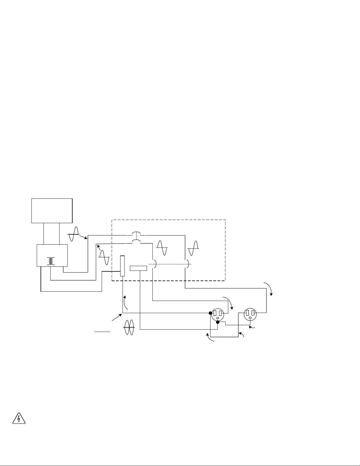
5.0 APPENDIX
Multiwire Branch Circuits (continued)
Correcting Multiwire Branch Circuit Wiring
Correcting multiwire branch circuit wiring is not an easy task. There are several approaches that
can be taken, each with its advantages and disadvantages.
Rewire existing multiwire branch circuits to conventional home run wiring. This requires a
qualified electrician (knowledgeable of multiwire branch circuit wiring) and is expensive. There
may be multiple multiwire branch circuits located throughout the structure, requiring complete
rewiring.
Add a second inverter in a series stacked arrangement. This is an expensive solution, but would
restore the original 240 VAC split-phase configuration. This solution may actually be less
expensive than having an electrician re-wire the multiwire branch circuits, plus it provides
increased power backup protection and can power 240 VAC loads.
Add a T240 Autotransformer to the output of the inverter to restore the split-phase configuration.
This is the least expensive and easiest method to correct for multiwire branch circuit wiring. Refer
to Figure 53. Using this method, half of the current is supplied to one leg of the circuit and half to
the other in a split-phase arrangement (180° out-of-phase). This will restore the original
functionality and safety to the multiwire branch circuit.
120 VAC
Inverter
(or generator)
Hot
Neutral
Auto-
transformer
White–Neutral
Load Center
L2
Ground
0 A
L1
25 A
Breaker
(Ganged)
Black–Hot
Single White–Neutral
Bare–Ground
Breaker
(Ganged)
25 A
Red–Hot
25 A
120 VAC
25 A
120 VAC
White–Neutral
Splice
Hot-L2
Hot–L1
The out-of-phase
currents subtract
Neutral
at this
point
Figure 53
Using A T240 Autotransformer in Multiwire Branch Circuit Wiring
25 A
Bare–Ground
Splice
062949-004
WARNING: UNTIL ONE OF THE SOLUTIONS ABOVE IS IMPLEMENTED, A STAND-ALONE
120 VAC INVERTER (OR GENERATOR) MUST NOT BE INSTALLED WHERE MULTIWIRE
BRANCH CIRCUITS EXIST.
68 ©2000 Xantrex Technology Inc.
Page 77

6.0 WARRANTY
Limited Warranty
Xantrex warrants its power products against defects in materials and workmanship for a
period of two (2) years from the date of purchase, established by proof of purchase or formal
warranty registration, and extends this warranty to all purchasers or owners of the product during
the warranty period. Xantrex does not warrant its products from any and all defects:
arising out of material or workmanship not provided by Xantrex or its Authorized Service
Centers;
when the product is installed or exposed to an unsuitable environment as evidenced by
generalized corrosion or biological infestation;
resulting from abnormal use of the product, alteration, or use in violation of the instructions;
in components, parts, or products expressly warranted by another manufacturer.
Xantrex agrees to supply all parts and labor to repair or replace defects covered by this
warranty with parts or products of original or improved design, at the company's option. Xantrex
also reserves the right to improve the design of its products without obligation to modify or upgrade
those previously manufactured. Defective products must be returned to Xantrex or its Authorized
Service Center in the original packaging or equivalent. The cost of transportation and insurance on
items returned for service is the responsibility of the customer. Return transportation (UPS Ground
or equivalent) as well as insurance on all repaired items is paid by Xantrex.
All remedies and the measure of damages are limited to the above. Xantrex shall in no
event be liable for consequential, incidental, contingent, or special damages, even if Xantrex has
been advised of the possibility of such damages. Any and all other warranties, expressed or implied,
arising by law, course of dealing, course of performance, usage of trade or otherwise, including, but
not limited to, implied warranties of merchantability and fitness for a particular purpose, are limited in
duration for a period of two (2) years from the original date of purchase.
Some states or counties do not allow limitations on the term of an implied warranty, or the
exclusion or limitation of incidental or consequential damage, which means the limitations and
exclusions of this warranty may not apply to you. Even though this warranty gives you specific legal
rights, you may also have other rights which vary from state to state.
Xantrex Technology Inc., 5916 195th Northeast, Arlington, WA 98223, U.S.A. t: 360/435.8826, f: 360/435.3945
www.xantrex.com
©2000 Xantrex Technology Inc.
69
Page 78

6.0 WARRANTY
Life Support Policy
Xantrex does not recommend the use of any of its products in life support applications or direct
patient care. This especially applies to situations where the products failure or malfunction can be
reasonably expected to cause the failure or malfunction of the life support device, or to significantly
affect its safety or effectiveness.
Examples of life support devices include: neonatal oxygen analyzers, nerve stimulators (whether
used for anesthesia, pain relief, or other purposes), autotransfusion devices, blood pumps,
defibrillators, arrhythmia detectors and alarms, pacemakers, hemodialysis systems, peritoneal
dialysis systems, neonatal ventilator incubators, ventilators for both adults and infants, anesthesia
ventilators, and infusion pumps as well as any other devices designated as critical by the U.S.
FDA.
Xantrex will not knowingly sell its products for use in such applications unless it receives, in
writing, assurances satisfactory to The Company, that (a) the risks of injury or damage have been
minimized, (b) the customer assumes all such risks, and (c) the liability of Xantrex is adequately
protected.
Warranty Registration
To ensure proper registration, complete the Warranty Card and mail it to Xantrex within 10 days
from the date of original purchase. Also, keep your bill of sale as proof of purchase.
Warranty Repairs must be performed only at an authorized Xantrex service center or at the
Xantrex factory. Unauthorized repairs will void the warranty. A Return Merchandise Authorization
(RMA) number must be obtained PRIOR to shipment and must be included with the returned
product.
You can also register your product on-line at the Xantrex/Trace Web Site. Go to:
www.traceengineering.com and locate quick links on the home page. Click on the Technical
Support window and select Warranty Registration.
Xantrex Technology Inc., 5916 195th Northeast, Arlington, WA 98223, U.S.A. t: 360/435.8826, f: 360/435.3945
www.xantrex.com
70
©2000 Xantrex Technology Inc.
Page 79

7.0 SERVICE INFORMATION
Xantrex Technology Inc. takes great pride in its products and makes every effort to ensure your
unit fully meets your independent powering needs.
If your product needs repair, contact our Service department at: (360) 435-8826 to obtain an
RMA# and shipping information; or, fax this page with the following information to: (360) 474-0616.
Please provide:
Model Number: _______________________________________________________
Serial Number: _______________________________________________________
Purchase Date: _______________________________________________________
Problem: ____________________________________________________________
Include a telephone number where you can be reached during business hours and a complete
return shipping address (P.O. Box numbers are not acceptable).
Name: ______________________________________________________________
Address: ____________________________________________________________
City: _______________________________________________________________
State / Province: ______________________________________________________
Zip / Postal Code: _____________________________________________________
Country: ____________________________________________________________
Phone: (
) ________________________________________________________
FAX: ( ) __________________________________________________________
E-mail Address: ______________________________________________________
Xantrex Technology Inc., 5916 195th Northeast, Arlington, WA 98223, U.S.A. t: 360/435.8826, f: 360/435.3945
www.xantrex.com
©2000 Xantrex Technology Inc.
71
Page 80

8.0 SPECIFICATIONS
DR Series Specifications
MODEL DR1512 DR2412 DR1524 DR2424 DR3624
Continuous Power
Efficiency 94% max 94% max 94% max 95% max 95% max
Input Current
Search Mode 0.045 amps 0.055 amps 0.030 amps 0.030 amps 0.030 amps
Full Voltage 0.700 amps 0.900 amps 0.350 amps 0.450 amps 0.500 amps
Rated Power 165 amps 280 amps 80 amps 140 amps 210 amps
Short Circuit 400 amps 800 amps 280 amps 560 amps 720 amps
Input Voltage (Nominal) 12 VDC 12 VDC 24 VDC 24 VDC 24 VDC
Input Voltage Range 10.8-15.5 VDC 10.8-15.5 VDC 21.6-31 VDC 21.6-31 VDC 21.6-31 VDC
Auto Low Battery Protection 11 V or defeated 11 V or defeated 22 V or defeated 22 V or defeated 22 V or defeated
Charger Rate (Adjustable) 0-70 amps 0-120 amps 0-35 amps 0-70 amps 0-70 amps
Unit Weight 35 lb. (16 kg) 45 lb. (21 kg) 35 lb. (16 kg) 40 lb. (19 kg) 45 lb. (21 kg)
E models 39 lb. (18 kg) N/A 39 lb. (18 kg) 45 lb. (21 kg) N/A
Common Specifications
Voltage Regulation (Max) +/- 5%
Voltage Regulation
Waveform modified sine wave
Power Factor (allowed) 0 to 1
Frequency Regulation 60 Hz ± 0.04%
E models 50 Hz ± 0.04%
J models 50 Hz ± 0.04%
K models 50 Hz ± 0.04%
Standard Output Voltage 120 VAC @ 60 Hz
E models 230 VAC @ 50 Hz
W models 220 VAC @ 60 Hz
J models 105 VAC @ 50 Hz
K models 105 VAC @ 60 Hz
Adjustable Load Sensing 5 watt minimum
Series Operation for 120/240 VAC yes
E, W models no
Forced Air Cooling variable speed fan
Automatic Transfer Relay 30 amps
E models 20 amps
W models 20 amps
Number of Charging Profiles 10
Three Stage Charging yes (float, absorption, bulk)
Temperature Comp Probe optional
Remote Control optional
(@ 20 °C) 1500 VA 2400 VA 1500 VA 2400 VA 3600 VA
(Typ) +/- 2.5%
Environmental Characteristics
Ambient Temp Range
Operating 0 °C to +50 °C
Nonoperating -55 °C to +75 °C
Altitude
Operating 15,000 feet
Nonoperating 50,000 feet
Dimensions* 8.5 W x 7.25 H x 21 D
Mounting wall-mount (with 16 mounting centers)
*Allows for hardware extensions such as mounting rails, DC terminals, and front panel controls.
Specifications subject to change without notice.
21.6 cm W x 18.4 cm H x 54.6 cm D
shelf-mount
72 ©2000 Xantrex Technology Inc.
Page 81

Page 82

Page 83

Page 84

Xantrex Technology Inc.
5916 195th Northeast
Arlington, WA 98223
U.S.A.
t: 360/435.8826
f: 360/435.3945
www.xantrex.com
Printed in U.S.A.
© 2000 Xantrex Technology Inc.
P/N 975-0012-01-01 Rev. A 12/00
 Loading...