

Page 1
Angle grinder
Winkelschleifer
Meuleuse d’angle
Smerigliatrice angolare
Amoladora angular
Rebarbadora angular
Szlierka kątowa
Sarokcsiszoló
Polizor unghiular
Úhlová bruska
Uhlová brúska
WX721 WX722 WX722.1
EN
ES
NL
PL
HU
RO
CZ
SK
P06
D
F
I
P16
P27
P38
P49
P59
P69
P79
P90
P100
P109
Page 2

Original instructions EN
Originalbetriebsanleitung D
Notice originale F
Istruzioni originali I
Manual original ES
Oorspronkelijke gebruiksaanwijzing NL
Tłumaczenie oryginalnych instrukcji PL
Eredeti használati utasítás HU
Traducerea instrucţiunilor iniţiale RO
Překlad původních pokynů CZ
Preklad pôvodných pokynov SK
Page 3

Page 4
1
2
10
12
4
13
3
5
3
4
11
14
9 8 7 6
Page 5
9
11
A B C1
a
b
C2 D E
7
4
8
7
4
8
4
3
Page 6

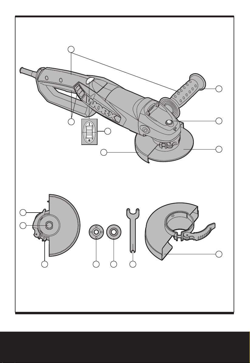
1. HAND GRIP AREAS
2. ANTI-VIBRATION AUXILIARY HANDLE
3. SPINDLE LOCK BUTTON
4. DISC*
5. WHEEL GUARD FOR GRINDING
6. SPANNER
7. INNER FLANGE
8. OUTER FLANGE
9. CLAMP ADJUSTMENT NUT
10. SPINDLE
11. GUARD CLAMPING LEVER
12. SAFETY ON/OFF SWITCH
13. VARIABLE SPEED CONTROL (WX722 WX722.1)
14. WHEEL GUARD FOR CUTTING*
* Not all the accessories illustrated or described are included in standard delivery.
6
Angle grinder EN
Page 7
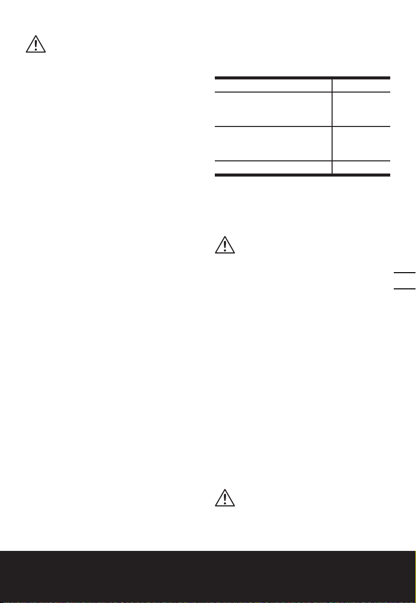
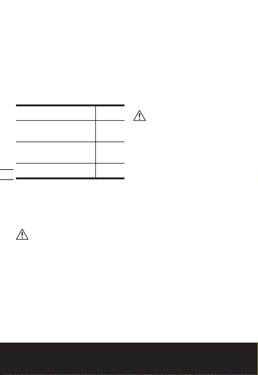
TECHNICAL DATA
Type WX721 WX722 WX722.1 (7- designation of machinery, representative of angle
grinder)
WX721 WX722 WX722.1
Voltage 220-240V~50/60Hz
Power input 1010W 1200W
Rated speed 12000/min
Speed control adjustment
Disc size 125mm
Disc bore 22.2mm
Spindle thread M14
Protection class
Machine weight 2.2kg
/ 3500-12000/min
/II
NOISE INFORMATION
A weighted sound pressure LpA: 87.3dB(A)
A weighted sound power LwA: 98.3dB(A)
KpA&KwA 3.0dB(A)
Wear ear protection when sound pressure is over 80dB(A)
7
VIBRATION INFORMATION
Vibration total values (triax vector sum) determined according to EN 60745:
Typical weighted vibration
The declared vibration total value may be used for comparing one tool with another, and may
also be used in a preliminary assessment of exposure.
WARNING: The vibration emission value during actual use of the power tool can differ
from the declared value depending on the ways in which the tool is used dependant on
the following examples and other variations on how the tool is used:
How the tool is used and the materials being cut .
The tool being in good condition and well maintained
The use the correct accessory for the tool and ensuring it is sharp and in good condition.
The tightness of the grip on the handles and if any anti vibration accessories are used.
And the tool is being used as intended by its design and these instructions.
Vibration emission value ah =5.20m/s
Uncertainty K = 1.5m/s²
2
Angle grinder EN
Page 8

This tool may cause hand-arm vibration syndrome if its use is not adequately managed.
WARNING: To be accurate, an estimation of exposure level in the actual conditions of use
should also take account of all parts of the operating cycle such as the times when the tool
is switched off and when it is running idle but not actually doing the job. This may significantly
reduce the exposure level over the total working period.
Helping to minimise your vibration exposure risk.
Maintain this tool in accordance with these instructions and keep well lubricated (where
appropriate).
If the tool is to be used regularly then invest in anti vibration accessories.
Avoid using tools in temperatures of 10oC or less.
Plan your work schedule to spread any high vibration tool use across a number of days.
ACCESSORIES
Spanner 1
Anti-vibration auxiliary handle 1
Metal grinding disc 1
We recommend that you purchase your accessories from the same store that sold you the
tool. Use good quality accessories marked with a well-known brand name. Choose the type
according to the work you intend to undertake. Refer to the accessory packaging for further
details. Store personnel can assist you and offer advice.
8
Angle grinder EN
Page 9

SAFETY INSTRUCTIONS
FOR ALL OPERATIONS
SAFETY WARNINGS COMMON FOR
GRINDING OR ABRASIVE CUTTING-OFF
OPERATIONS:
a) This power tool is intended to
function as a grinder or cut-off
tool. Read all safety warnings,
instructions, illustrations and
specifications provided with this
power tool. Failure to follow all
instructions listed below may result in
electric shock, fire and/or serious injury.
b) Operations such as sanding,
wire brushing, polishing are not
recommended to be performed with
this power tool. Operations for which
the power tool was not designed may
create a hazard and cause personal injury.
c) Do not use accessories which
are not specifically designed
and recommended by the tool
manufacturer. Just because the
accessory can be attached to your power
tool, it does not assure safe operation.
d) The rated speed of the accessory
must be at least equal to the
maximum speed marked on the
power tool. Accessories running faster
than their rated speed can break and fly
apart.
e) The outside diameter and the
thickness of your accessory must
be within the capacity rating of your
power tool. Incorrectly sized accessories
cannot be adequately guarded or
controlled.
f) The arbour size of wheels, flanges,
backing pads or any other accessory
must properly fit the spindle of the
power tool. Accessories with arbour
holes that do not match the mounting
hardware of the power tool will run out
of balance, vibrate excessively and may
cause loss of control.
g) Do not use a damaged accessory.
Before each use inspect the
accessory such as abrasive wheels
for chips and cracks backing pad
for cracks, tear or excess wear,
wire brush for loose or cracked
wires. If power tool or accessory
is dropped, inspect for damage or
install an undamaged accessory.
After inspecting and installing an
accessory, position yourself and
bystanders away from the plane of
the rotating accessory and run the
power tool at maximum no-load
speed for one minute. Damaged
accessories will normally break apart
during this test time.
h) Wear personal protective equipment.
Depending on application, use face
shield, safety goggles or safety
glasses. As appropriate, wear dust
mask, hearing protectors, gloves and
workshop apron capable of stopping
small abrasive or workpiece
fragments. The eye protection must
be capable of stopping flying debris
generated by various operations . The
dust mask or respirator must be capable
of filtrating particles generated by your
operation. Prolonged exposure to high
intensity noise may cause hearing loss.
i) Keep bystanders a safe distance
away from work area. Anyone
entering the work area must wear
personal protective equipment.
Fragments of workpiece or of a broken
accessory may fly away and cause injury
beyond immediate area of operation.
j) Hold power tool by insulated
gripping surfaces only, when
performing an operation where
the cutting accessory may contact
hidden wiring or its own cord. Cutting
accessory contacting a “live” wire may
make exposed metal parts of the power
tool “live” and could give the operator an
electric shock.
k) Position the cord clear of the
spinning accessory. If you lose control,
the cord may be cut or snagged and
your hand or arm may be pulled into the
spinning accessory.
l) Never lay the power tool down
until the accessory has come to a
9
Angle grinder EN
Page 10

complete stop. The spinning accessory
may grab the surface and pull the power
tool out of your control.
m) Do not run the power tool while
carrying it at your side. Accidental
contact with the spinning accessory could
snag your clothing, pulling the accessory
into your body.
n) Regularly clean the power tool’s air
vents. The motor’s fan will draw the
dust inside the housing and excessive
accumulation of powdered metal may
cause electrical hazards.
o) Do not operate the power tool near
flammable materials. Sparks could
ignite these materials.
p) Do not use accessories that require
liquid coolants. Using water or other
liquid coolants may result in electrocution
or shock.
q) Your hand must hold on the handle when
you are working. Always use the auxiliary
handles supplied with the tool. Loss of
control can cause personal injury.
10
FURTHER SAFETY INSTRUCTIONS FOR
ALL OPERATIONS
KICKBACK AND RELATED WARNINGS
Kickback is a sudden reaction to a pinched or
snagged rotating wheel, backing pad, brush
or any other accessory. Pinching or snagging
causes rapid stalling of the rotating accessory
which in turn causes the uncontrolled power
tool to be forced in the direction opposite of
the accessory’s rotation at the point of the
binding.
For example, if an abrasive wheel is snagged
or pinched by the workpiece, the edge of the
wheel that is entering into the pinch point can
dig into the surface of the material causing
the wheel to climb out or kick out. The wheel
may either jump toward or away from the
operator, depending on direction of the
wheel’s movement at the point of pinching.
Abrasive wheels may also break under these
conditions.
Kickback is the result of power tool misuse
and/or incorrect operating procedures or
conditions and can be avoided by taking
proper precautions as given below.
a) Maintain a firm grip on the power
tool and position your body and
arm to allow you to resist kickback
forces. Always use auxiliary handle,
if provided, for maximum control
over kickback or torque reaction
during start-up. The operator can
control torque reactions or kickback
forces, if proper precautions are taken.
b) Never place your hand near the
rotating accessory. Accessory may
kickback over your hand.
c) Do not position your body in the
area where power tool will move
if kickback occurs. Kickback will
propel the tool in direction opposite to
the wheel’s movement at the point of
snagging.
d) Use special care when working
corners, sharp edges etc. Avoid
bouncing and snagging the
accessory. Corners, sharp edges or
bouncing have a tendency to snag the
rotating accessory and cause loss of
control or kickback.
e) Do not attach a saw chain
woodcarving blade or toothed saw
blade. Such blades create frequent
kickback and loss of control.
ADDITIONAL SAFETY INSTRUCTIONS
FOR GRINDING AND
CUTTING-OFF OPERATIONS
SAFETY WARNINGS SPECIFIC FOR
GRINDING AND ABRASIVE CUTTING-OFF
OPERATIONS:
a) Use only wheel types that are
recommended for your power tool
and the specific guard designed for
the selected wheel. Wheels for which
the power tool was not designed cannot
be adequately guarded and are unsafe.
b) The guard must be securely attached
to the power tool and positioned
for maximum safety, so the least
amount of wheel is exposed towards
the operator. The guard helps to protect
operator from broken wheel fragments
and accidental contact with wheel and
sparks that could ignite clothing.
Angle grinder EN
Page 11

c) Wheels must be used only for
recommended applications. For
example: do not grind with the
side of cut-off wheel. Abrasive cut-
off wheels are intended for peripheral
grinding, side forces applied to these
wheels may cause them to shatter.
d) Always use undamaged wheel
flanges that are of correct size and
shape for your selected wheel.
Proper wheel flanges support the wheel
thus reducing the possibility of wheel
breakage. Flanges for cut-off wheels may
be different from grinding wheel flanges.
e) Do not use worn down wheels from
larger power tools. Wheel intended for
larger power tool is not suitable for the
higher speed of a smaller tool and may
burst.
ADDITIONAL SAFETY INSTRUCTIONS
FOR CUTTING-OFF OPERATIONS
ADDITIONAL SAFETY WARNINGS
SPECIFIC FOR ABRASIVE CUTTING-OFF
OPERATIONS:
a) Do not “jam” the cut-off wheel
or apply excessive pressure. Do
not attempt to make an excessive
depth of cut. Overstressing the wheel
increases the loading and susceptibility to
twisting or binding of the wheel in the cut
and the possibility of kickback or wheel
breakage.
b) Do not position your body in
line with and behind the rotating
wheel. When the wheel, at the point of
operation, is moving away from your
body, the possible kickback may propel
the spinning wheel and the power tool
directly at you.
c) When wheel is binding or when
interrupting a cut for any reason,
switch off the power tool and hold
the power tool motionless until the
wheel comes to a complete stop.
Never attempt to remove the cut-off
wheel from the cut while the wheel
is in motion otherwise kickback may
occur. Investigate and take corrective
action to eliminate the cause of wheel
binding.
d) Do not restart the cutting operation
in the workpiece. Let the wheel
reach full speed and carefully reenter
the cut. The wheel may bind, walk up or
kickback if the power tool is restarted in
the workpiece.
e) Support panels or any oversized
workpiece to minimize the risk of
wheel pinching and kickback. Large
workpieces tend to sag under their own
weight. Supports must be placed under
the workpiece near the line of cut and
near the edge of the workpiece on both
sides of the wheel.
f) Use extra caution when making a
“pocket cut” into existing walls or
other blind areas. The protruding wheel
may cut gas or water pipes, electrical
wiring or objects that can cause kickback.
11
Angle grinder EN
Page 12
SYMBOLS OPERATING INSTRUCTIONS
To reduce the risk of injury, user
must read instruction manual
Warning
Double insulation
NOTE: Before using the tool, read the
instruction book carefully.
INTENDED USE
The machine is intended for cutting,
roughing and brushing metal and stone
materials without using water. For cutting
metal, a special protection guard for cutting
(accessory) must be used.
12
Wear eye protection
Wear ear protection
Wear dust mask
This product has been marked
with a symbol relating to removing
electric and electronic waste. This
means that this product shall not
be discarded with household waste
but that it shall be returned to a
collection system which conforms
to the European Directive 2002/96/
CE. It will then be recycled or
dismantled in order to reduce the
impact on the environment. Electric
and electronic equipment can be
hazardous for the environment
and for human health since they
contain hazardous substances.
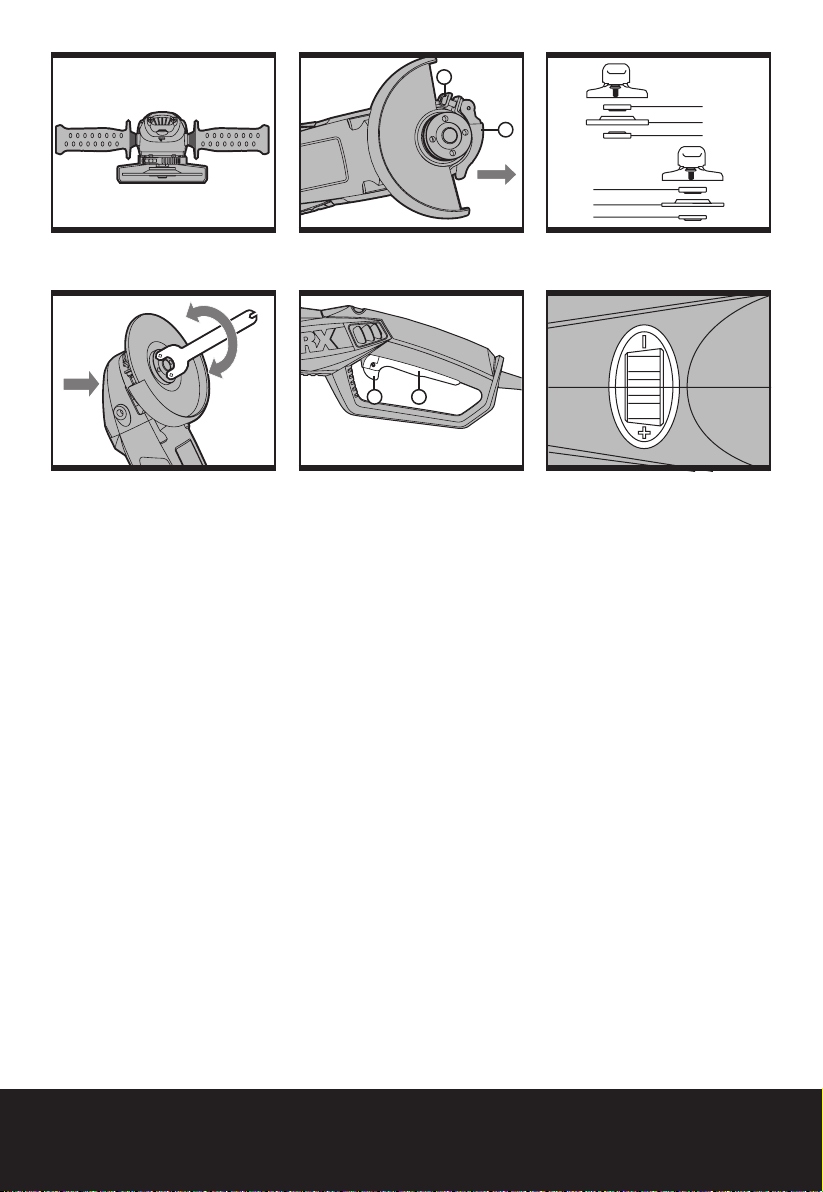
1. INSTALLING THE AUXILIARY
HANDLE (See Fig. A)
You have the option of two working positions
to provide the safest and most comfortable
control of your angle grinder. The handle is
screwed clockwise into either hole on the
sides of the gear case.
Anti-vibration auxiliary handle
The anti-vibration auxiliary handle reduces
the vibrations, making operation more
comfortable and secure.
2. ADJUSTING WHEEL GUARD
(See Fig. B)
Before any work on the machine itself,
pull the mains plug.
For work with grinding or cutting discs,
the wheel guard must be mounted.
WHEEL GUARD FOR GRINDING
The coded projection on the wheel guard
(5) ensures that only a guard that fits the
machine type can be mounted.
Open the clamping lever (11). Place the wheel
guard (5) with coded projection into the
coded groove on the spindle of the machine
head and rotate to the required position
(working position).
To fasten the wheel guard (5), close the
clamping lever (11).
The closed side of the wheel guard (5) must
always point to the operator.
NOTE: With the clamping lever (11) open the
clamp adjusting nut (9) can be adjusted to
ensure the guard is securely clamped after
the clamping lever (11) is finally closed.
Angle grinder EN
Page 13
WHEEL GUARD FOR CUTTING
WARNING! For cutting metal,always
work with the wheel guard for
cutting(14). The wheel guard for cutting (14)
is mounted in the same manner as the wheel
guard for grinding(5).
3. FITTING THE DISCS (See Fig. C1.C2 )
Put the inner flange onto the tool spindle.
Ensure it is located on the two flats of spindle.
Place the disc on the tool spindle and inner
flange. Ensure it is correctly located. Fit the
threaded outer flange making sure it is facing
in the correct direction for the type of disc
fitted. For grinding discs, the flange is fitted
with the raised portion facing towards the
disc. For cutting discs, the flange is fitted
with the raised portion facing away from the
disc (See Fig. C1).
Press in the spindle lock button and rotate
the spindle by hand until it is locked. Keeping
the lock button pressed in, tighten the outer
flange with the spanner provided.
(See Fig. C2).
4. SAFETY ON/OFF SWITCH (See Fig. D)
Your switch is locked off to prevent
accidental starting. With your hand on the
on/off switch (a) use your finger to push
lever (b) forward and then depress on/off
switch (a). Then release lever (b). Your tool
is now on. To switch off just release on/off
switch.
SOFT START MOTOR(WX722.1)
Internal electronic components allow the
motor speed to increase slowly, which
reduces the“twisting”effect on your wrists
due to the high power motor.
5. VARIABLE SPEED CONTROL
(See Fig. E)(WX722/WX722.1)
Adjust the thumb-wheel to increase or
decrease the speed (See Fig. E) according
to the material, material thickness and disc/
accessory specification to be used (also
possible during no load operation). See Table
1 for general guidance on speed selection.
Avoid prolonged use at very low speeds
as this may damage your angle grinder’s
motor. The constant speed control electronic
circuit inside your angle grinder maintains a
nearly constant speed even when your angle
grinder is under load.
Table 1
Material Speed setting
Grinding ferrous metals,
cutting stone, brick, etc,
Wire cup brush
Grinding or sanding nonferrous metals, light grinding work
Polishing, light sanding work 1-3
6. SPINDLE LOCK BUTTON
Must only be used when changing a disc.
Never press when the disc is rotating!
7. TO USE THE GRINDER
ATTENTION: Do not switch the
grinder on whilst the disc is in
contact with the workpiece. Allow the
disc to reach full speed before starting
to grind.
Hold your angle grinder with one hand on the
main handle and other hand firmly around
the auxiliary handle.
Always position the guard so that as much
of the exposed disc as possible is pointing
away from you.
Be prepared for a stream of sparks when the
disc touches the metal.
For best tool control, material removal
and minimum overloading, maintain an
angle between the disc and work surface of
approximately 150 -300 when grinding.
Use caution when working into corners as
contact with the intersecting surface may
cause the grinder to jump or twist.
When grinding is complete allow the
workpiece to cool. Do not touch the hot
surface.
8. CUTTING
WARNING! For cutting metal, always
work with the wheel guard for cutting.
When cutting, do not press, tilt or oscillate
the machine. Work with moderate feed,
5-6
3-5
13
Angle grinder EN
Page 14

adapted to the material being cut.
Do not reduce the speed of running down
cutting discs by applying sideward pressure.
The direction in which the cutting is
performed is important.
The machine must always work in an upgrinding motion. Therefore, never move the
machine in the other direction! Otherwise,
the danger exists of it being pushed
uncontrolled out of the cut.
WORKING HINTS FOR YOUR
ANGLE GRINDER
1. Always start at no load to achieve
maximum speed then start working.
2. Do not force the disc to work faster,
reducing the Disc’s moving speed means
longer working time.
3. Always work with a 15-30 angle between
disc and workpiece. Larger angles will
cut ridges into the workpiece and affect
the surface finish. Move the angle grinder
14
across and back and forth over the
workpiece.
4. When using a cutting disc never change the
cutting angle otherwise you will stall the
disc and angle grinder motor or break the
disc. When cutting, only cut in the opposite
direction to the disc rotation. If you cut in
the same direction as the disc rotation the
disc may push itself out of the cut slot.
5. When cutting very hard material best
results can be achieved with a diamond
disc.
6. When using a diamond disc it will become
very hot. If this happens you will see a full
ring of sparks around the rotating disc.
Stop cutting and allow to cool at no load
speed for 2-3 minutes.
7. Always ensure the workpiece is firmly held
or clamped to prevent movement.
MAINTENANCE
Remove the plug from the socket
before carrying out any adjustment,
servicing or maintenance.
There are no user serviceable parts in your
power tool. Never use water or chemical
cleaners to clean your power tool. Wipe clean
with a dry cloth. Always store your power
tool in a dry place. Keep the motor ventilation
slots clean. Keep all working controls free
of dust. Occasionally you may see sparks
through the ventilation slots. This is normal
and w ill not damage your power tool.
If the supply cord is damaged, it must be
replaced by the manufacturer, its service
agent or similarly qualified persons in order
to avoid a hazard.
TROUBLESHOOTING
Although your new angle grinder is really
very simple to operate, if you do experience
problems, please check the following:
1. If your grinder will not operate check the
power at the main plug.
2. If your grinder wheel wobbles or vibrates,
check that outer flange is tight, check
that the wheel is correctly located on the
flange plate.
3. If there is any evidence that the wheel
is damaged do not use as the damaged
wheel may disintegrate, remove it and
replace with a new wheel. Dispose of old
wheels sensibly.
4. If working on aluminum or a similar soft
alloy, the wheel will soon become clogged
and will not grind effectively.
ENVIRONMENTAL
PROTECTION
This product has been marked with a
symbol relating to removing electric
and electronic waste. This means that
this product shall not be discarded with
household waste but that it shall be returned
to a collection system which conforms to the
European Directive 2002/96/CE. It will then
be recycled or dismantled in order to reduce
the impact on the environment. Electric and
electronic equipment can be hazardous for
the environment and for human health since
they contain hazardous substances.
Angle grinder EN
Page 15
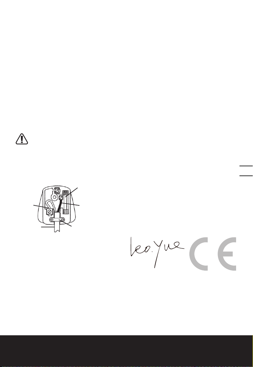
PLUG REPLACEMENT
(UK & IRELAND ONLY)
If you need to replace the fitted plug then follow the instructions below.
IMPORTANT
The wires in the mains lead are colored in
accordance with the following code:
BLUE =NEUTRAL BROWN =LIVE
As the colors of the wires in the mains lead of
this appliance may not correspond with the
colored markings identifying the terminals
in your plug, proceed as follows. The wire
which is colored blue must be connected
to the terminal which is marked with N.
The wire which is colored brown must be
connected to the terminal which is marked
with L.
WARNING!Never connect live or
neutral wires to the earth terminal of
the plug. Only fit an approved 13ABS1363/A
plug and the correct rated fuse.
NOTE: If a moulded plug is fitted and has
to be removed take great care in disposing
of the plug and severed cable, it must be
destroyed to prevent engaging into a socket.
13 Amp fuse approved
to BS1362
Connect
Blue to N
(neutral)
Outer sleeve
firmly clamped
Brown L (live)
Cable grip
DECLARATION OF
CONFORMITY
We,
POSITEC Germany GmbH
Konrad-Adenauer-Ufer 37
50668 Köln
Declare that the product,
Description
WORX Angle grinder
Type
WX721 WX722 WX722.1 (7- designation
of machinery, representative of Angle
grinder)
Function Peripheral and lateral grinding
Complies with the following directives,
2006/42/EC
2004/108/EC
2011/65/EU
Standards conform to:
EN 55014-1
EN 55014-2
EN 61000-3-2
EN 61000-3-3
EN 60745-1
EN 60745-2-3
The person authorized to compile the
technical file,
Name Russell Nicholson
Address Positec Power Tools (Europe)
Ltd, PO Box 152, Leeds, LS10 9DS, UK
15
2014/01/16
Leo Yue
POSITEC Quality Manager
Angle grinder EN
Page 16

1. HANDGRIFFBEREICHE
2. ANTI-VIBRATIONSHANDGRIFF
3. WELLENARRETIERUNGSKNOPF
4. SCHEIBE*
5. SCHLEIF-SCHUTZHAUBE
6. SCHRAUBENSCHLÜSSEL
7. INNENFLANSCH
8. GEGENFLANSCH
9. BÜGELSTELLMUTTER
10. WELLE
11. SPANNHEBEL SCHUTZHAUBE
12. SICHERHEITSEIN-/AUSSCHALTER
13. DREHZAHLREGELUNG (WX722 WX722.1)
14. SCHUTZHAUBE ZUM TRENNEN*
*Abgebildetes oder beschriebenes Zubehör gehört teilweise nicht zum Lieferumfang.
16
Winkelschleifer D
Page 17
TECHNISCHE DATEN
Typ WX721 WX722 WX722.1 (7-Bezeichnung der Maschine, Repräsentant der
Winkelschleifer)
WX721 WX722 WX722.1
Nennspannung 220-240V~50/60Hz
Nennleistung 1010W 1200W
Nenndrehzahl 12000/min
Drehzahleinstellbereich
Scheiben 125mm
Scheibenbohrung 22.2mm
Schleifspindelgewinde M14
Schutzklasse
Gewicht 2.2kg
/ 3500-12000/min
/II
INFORMATIONEN ÜBER LÄRM
Gewichteter Schalldruck LpA: 87.3dB(A)
Gewichtete Schallleistung LwA: 98.3dB(A)
KpA&KwA 3.0dB(A)
Tragen Sie bei einem Schalldruck über einen Gehörschutz 80dB(A)
17
INFORMATIONEN ÜBER VIBRATIONEN
Vibrationsgesamtmesswertermittlung gemäß EN 60745:
Typischer gewichteter Vibrationswert
Der angegebene Gesamtvibrationswert kann zum Vergleich eines Werkzeugs mit einem anderen
und auch zur vorläufigen Expositionsbewertung verwendet werden.
WARNUNG: Der Vibrationsemissionswert während des tatsächlichen Gebrauchs des
Elektrowerkzeugs kann vom angegebenen Wert abweichen, je nachdem, wie das Werkzeug
gemäß folgender Beispiele und anderweitiger Verwendungsmöglichkeiten eingesetzt wird:
Wie das Werkzeug verwendet wird und Materialen geschnitten.
Das Werkzeug ist in gutem Zustand und gut gepflegt.
Verwendung des richtigen Zubehörs für das Werkzeug und Gewährleistung seiner Schärfe und
seines guten Zustands.
Vibrationsemissionswert ah =5.20m/s
Unsicherheit K = 1.5m/s²
2
Winkelschleifer D
Page 18

Die Festigkeit der Handgriffe und ob Antivibrationszubehör verwendet wird.
Und ob das verwendete Werkzeug dem Design und diesen Anweisungen entsprechend verwendet wird.
Wird dieses Werkzeug nicht anemessen gehandhabt, kann es ein Hand-ArmVibrationssyndrom erzeugen.
WARNUNG: Um genau zu sein, sollte ein Abschätzung des Belastungsgrades aller
Arbeitsabschnitte während tatsächlicher Verwendung berücksichtigt werden, z.B. die Zeiten,
wenn das Werkzeug ausgeschaltet ist, und wenn es sich im Leerlauf befindet und eigentlich nicht
eingesetzt wird. Auf diese Weise kann der Belastungsgrad während der gesamten Arbeitszeit
wesentlich gemindert werden.
Minimieren Sie Ihr Risiko, dem Sie bei Vibrationen ausgesetzt sind.
Pflegen Sie dieses Werkzeug diesen Anweisungen entsprechend und achten Sie auf eine gute
Einfettung (wo erforderlich).
Bei regelmäßiger Verwendung dieses Werkzeugs sollten Sie in Antivibrationszubehör investieren.
Vermeiden Sie den Einsatz von Werkzeugen bei Temperaturen von 10ºC oder darunter.
Machen Sie einen Arbeitsplan, um die Verwendung von hochvibrierenden Werkzeugen auf
mehrere Tage zu verteilen.
ZUBEHÖRTEILE
Schlüssel 1
Anti-vibrationshandgriff 1
Metall-Schleifscheibe 1
18
Wir empfehlen Ihnen, sämtliche Zubehörteile beim selben Fachhändler zu beziehen, bei dem
Sie auch Ihr Elektrowerkzeug gekauft haben. Verwenden Sie nur hochwertige Zubehörteile von
namhaften Herstellern. Weitere Informationen finden Sie auf der Verpackung der Zubehörteile.
Auch Ihr Fachhändler berät Sie gerne.
Winkelschleifer D
Page 19

ZUSÄTZLICHE
SICHERHEITSHINWEISE
FÜR WINKELSCHLEIFER
GEMEINSAME WARNHINWEISE ZUM
SCHLEIFEN, TRENNSCHLEIFEN.:
1. Dieses Elektrowerkzeug ist
zu verwenden als Schleifer,
Trennschleifmaschine. Beachten Sie
alle Warnhinweise, Anweisungen,
Darstellungen und Daten, die Sie
mit dem Gerät erhalten. Wenn Sie
die folgenden Anweisungen nicht
beachten, kann es zu elektrischem Schlag,
Feuer und/oder schweren Verletzungen
kommen.
2. Dieses Elektrowerkzeug ist nicht
geeignet zum Sandpapierschleifen,
Arbeiten mit Drahtbürsten,
Polieren. Verwendungen, für die das
Elektrowerkzeug nicht vorgesehen ist,
können Gefährdungen und Verletzungen
verursachen.
3. Verwenden Sie kein Zubehör, das
vom Hersteller nicht speziell für
dieses Elektrowerkzeug vorgesehen
und empfohlen wurde. Nur weil Sie
das Zubehör an Ihrem Elektrowerkzeug
befestigen können, garantiert das keine
sichere Verwendung.
4. Die zulässige Drehzahl des
Einsatzwerkzeugs muss mindestens
so hoch sein wie die auf dem
Elektrowerkzeug angegebene
Höchstdrehzahl. Zubehör, das sich
schneller als zulässig dreht, kann zerstört
werden.
5. Außendurchmesser und Dicke des
Einsatzwerkzeugs müssen den
Maßangaben Ihres Elektrowerkzeugs
entsprechen. Falsch bemessene
Einsatzwerkzeuge können nicht
ausreichend abgeschirmt oder kontrolliert
werden.
6. Schleifscheiben, Flansche,
Schleifteller oder anderes Zubehöhr
müssen genau auf die Schleifspindel
Ihres Elektrowerkzeugs passen.
Einsatzwerkzeuge, die nicht genau auf
die Schleifspindel des Elektrowerkzeugs
passen, drehen sich ungleichmäßig,
vibrieren sehr stark und können zum
Verlust der Kontrolle führen.
7. Verwenden Sie keine beschädigten
Einsatzwerkzeuge. Kontrollieren
Sie vor jeder Verwendung
Einsatzwerkzeuge wie
Schleifscheiben auf Absplitterungen
und Risse, Schleifteller auf Risse,
Verschleiß oder starke Abnutzung.
Wenn das Elektrowerkzeug oder
das Einsatzwerkzeug herunterfällt,
überprüfen Sie, ob es beschädigt
ist, oder verwenden Sie ein
unbeschädigtes Einsatzwerkzeug.
Wenn Sie das Einsatzwerkzeug
kontrolliert und eingesetzt
haben, halten Sie und in der
Nähe befindliche Personen sich
außerhalb der Ebene des rotierenden
Einsatzwerkzeugs und lassen Sie
das Gerät eine Minute lang mit
Höchstdrehzahl laufen. Beschädigte
Einsatzwerkzeuge brechen meist in dieser
Testzeit.
8. Tragen Sie persönliche
Schutzausrüstung. Verwenden
Sie je nach Anwendung
Vollgesichtsschutz, Augenschutz
oder Schutzbrille. Soweit
angemessen, tragen Sie Staubmaske,
Gehörschutz, Schutzhandschuhe
oder Spezialschürze, die kleine
Schleif- und Materialpartikel von
Ihnen fernhält. Die Augen sollen
vor herumfliegenden Fremdkörpern
geschützt werden, die bei verschiedenen
Anwendungen entstehen. Staub- oder
Atemschutzmaske müssen den bei der
Anwendung entstehenden Staub filtern.
Wenn Sie lange lautem Lärm ausgesetzt
sind, können Sie einen Hörverlust
erleiden.
9. Achten Sie bei anderen Personen
auf sicheren Abstand zu Ihrem
Arbeitsbereich. Jeder, der den
Arbeitsbereich betritt, muss
persönliche Schutzausrüstung
tragen. Bruchstücke des Werkstücks oder
gebrochener Einsatzwerkzeuge können
19
Winkelschleifer D
Page 20

wegfliegen und Verletzungen auch
außerhalb des direkten Arbeitsbereichs
verursachen.
10. Halten Sie das Gerät nur an den
isolierten Griffflächen, wenn Sie
Arbeiten ausführen, bei denen
das Einsatzwerkzeug verborgene
Stromleitungen oder das eigene
Netzkabel treffen kann. Der Kontakt
mit einer spannungsführenden Leitung
kann auch metallene Geräteteile
unter Spannung setzen und zu einem
elektrischen Schlag führen.
11. Halten Sie das Netzkabel von sich
drehenden Einsatzwerkzeugen
fern. Wenn Sie die Kontrolle über das
Gerät verlieren, kann das Netzkabel
durchtrennt oder erfasst werden und Ihre
Hand oder Ihr Arm in das sich drehende
Einsatzwerkzeug geraten.
12. Legen Sie das Elektrowerkzeug
niemals ab, bevor das
Einsatzwerkzeug völlig zum
Stillstand gekommen ist. Das sich
20
drehende Einsatzwerkzeug kann in
Kontakt mit der Ablagefläche geraten,
wodurch Sie die Kontrolle über das
Elektrowerkzeug verlieren können.
13. Lassen Sie das Elektrowerkzeug nicht
laufen, während Sie es tragen. Ihre
Kleidung kann durch zufälligen Kontakt
mit dem sich drehenden Einsatzwerkzeug
erfasst werden, und das Einsatzwerkzeug
sich in Ihren Körper bohren.
14. Reinigen Sie regelmäßig
die Lüftungsschlitze Ihres
Elektrowerkzeugs. Das Motorgebläse
zieht Staub in das Gehäuse, und eine
starke Ansammlung von Metallstaub
kann elektrische Gefahren verursachen.
15. Verwenden Sie das Elektrowerkzeug
nicht in der Nähe brennbarer
Materialien. Funken können diese
Materialien entzünden.
16. Verwenden Sie keine
Einsatzwerkzeuge, die flüssige
Kühlmittel erfordern. Die Verwendung
von Wasser oder anderen flüssigen
Kühlmitteln kann zu einem elektrischen
Schlag führen.
17. Ihre Hand muss den Griff während
der Arbeit festhalten. Verwenden Sie
immer die dem Werkzeug mitgelieferten
Hilfsgriffe. Kontrollverlust kann
Körperverletzungen verursachen.
WEITERE SICHERHEITSHINWEISE FÜR
ALLE ANWENDUNGEN
RÜCKSCHLAG UND ENTSPRECHENDE
WARNHINWEISE
Rückschlag ist die plötzliche Reaktion infolge
eines hakenden oder blockierten drehenden
Einsatzwerkzeugs, wie Schleifscheibe,
Schleifteller, Drahtbürste usw. Verhaken oder
Blockieren führt zu einem abrupten Stopp des
rotierenden Einsatzwerkzeugs. Dadurch wird
ein unkontrolliertes Elektrowerkzeug gegen
dieDrehrichtung des Einsatzwerkzeugs an der
Blockierstelle beschleunigt.
Wenn z. B. eine Schleifscheibe im Werkstück
hakt oder blockiert, kann sich die Kante der
Schleifscheibe, die in das Werkstück eintaucht,
verfangen und dadurch die Schleifscheibe
ausbrechen oder einen Rückschlag
verursachen. Die Schleifscheibe bewegt sich
dann auf die Bedienperson zu oder von ihr
weg, je nach Drehrichtung der Scheibe an der
Blockierstelle. Hierbei können Schleifscheiben
auch brechen.
Ein Rückschlag ist die Folge eines
falschen oder fehlerhaften Gebrauchs des
Elektrowerkzeugs. Er kann durch geeignete
Vorsichtsmaßnahmen, wie nachfolgend
beschrieben, verhindert werden.
1. Halten Sie das Elektrowerkzeug gut
fest und bringen Sie Ihren Körper
und Ihre Arme in eine Position, in der
Sie die Rückschlagkräfte abfangen
können. Verwenden Sie immer
den Zusatzgriff, falls vorhanden,
um die größtmögliche Kontrolle
über Rückschlagkräfte oder
Reaktionsmomente beim Hochlauf
zu haben. Die Bedienperson kann
durch geeignete Vorsichtsmaßnahmen
die Rückschlag- und Reaktionskräfte
beherrschen.
2. Bringen Sie Ihre Hand nie in die Nähe
sich drehender Einsatzwerkzeuge.
Das Einsatzwerkzeug kann sich beim
Winkelschleifer D
Page 21

Rückschlag über Ihre Hand bewegen.
3. Meiden Sie mit Ihrem Körper den
Bereich, in den das Elektrowerkzeug
bei einem Rückschlag bewegt wird.
Der Rückschlag treibt das Elektrowerkzeug
in die Richtung entgegengesetzt zur
Bewegung der Schleifscheibe an der
Blockierstelle.
4. Arbeiten Sie besonders vorsichtig
im Bereich von Ecken, scharfen
Kanten usw. Verhindern Sie, dass
Einsatzwerkzeuge vom Werkstück
zurückprallen und verklemmen. Das
rotierende Einsatzwerkzeug neigt bei
Ecken, scharfen Kanten oder wenn es
abprallt, dazu, sich zu verklemmen. Dies
verursacht einen Kontrollverlust oder
Rückschlag.
5. Verwenden Sie kein Ketten- oder
gezähntes Sägeblatt. Solche
Einsatzwerkzeuge verursachen häufig
einen Rückschlag oder den Verlust der
Kontrolle über das Elektrowerkzeug.
BESONDERE SICHERHEITSHINWEISE
ZUM SCHLEIFEN UND TRENNSCHLEIFEN:
1. Verwenden Sie ausschließlich
die für Ihr Elektrowerkzeug
zugelassenen Schleifkörper und die
für diese Schleifkörper vorgesehene
Schutzhaube. Schleifkörper, die nicht
für das Elektrowerkzeug vorgesehen sind,
können nicht ausreichend abgeschirmt
werden und sind unsicher.
2. Die Schutzhaube muss sicher
am Elektrowerkzeug angebracht
und so eingestellt sein, dass ein
Höchstmaß an Sicherheit erreicht
wird, d. h. der kleinstmögliche Teil
des Schleifkörpers zeigt offen zur
Bedienperson. Die Schutzhaube soll
die Bedienperson vor Bruchstücken und
zufälligemKontakt mit dem Schleifkörper
schützen.
3. Schleifkörper dürfen nur für die
empfohlenen Einsatzmöglichkeiten
verwendet werden. Zum Beispiel:
Schleifen Sie nie mit der
Seitenfläche einer Trennscheibe.
Trennscheiben sind zum Materialabtrag
mit der Kante der Scheibe bestimmt.
Seitliche Krafteinwirkung auf diese
Schleifkörper kann sie zerbrechen.
4. Verwenden Sie immer unbeschädigte
Spannflansche in der richtigen Größe
und Form für die von Ihnen gewählte
Schleifscheibe. Geeignete Flansche
stützen die Schleifscheibe und verringern
so die Gefahr eines Schleifscheibenbruchs.
Flansche für Trennscheiben können
sich von den Flanschen für andere
Schleifscheiben unterscheiden.
5. Verwenden Sie keine abgenutzten
Schleifscheiben von größeren
Elektrowerkzeugen. Schleifscheiben
für größere Elektrowerkzeuge sind nicht
für die höheren Drehzahlen von kleineren
Elektrowerkzeugen ausgelegt und können
brechen.
ZUSÄZLICHE SICHERHEITSHINWEISE
ZUM TRENNSCHLEIFEN:
1. Vermeiden Sie ein Blockieren
der Trennscheibe oder zu hohen
Anpressdruck. Führen Sie keine
übermäßig tiefen Schnitte aus. Eine
Überlastung der Trennscheibe erhöht
deren Beanspruchung und die Anfälligkeit
zum Verkanten oder Blockieren und damit
die Möglichkeit eines Rückschlags oder
Schleifkörperbruchs.
2. Meiden Sie den Bereich vor und
hinter der rotierenden Trennscheibe.
Wenn Sie die Trennscheibe im Werkstück
von sich wegbewegen, kann im Falle
eines Rückschlags das Elektrowerkzeug
mit der sich drehenden Scheibe direkt auf
Sie zugeschleudert werden.
3. Falls die Trennscheibe verklemmt
oder Sie die Arbeit unterbrechen,
schalten Sie das Gerät aus und
halten Sie es ruhig, bis die Scheibe
zum Stillstand gekommen ist.
Versuchen Sie nie, die noch laufende
Trennscheibe aus dem Schnitt zu
ziehen, sonst kann ein Rückschlag
erfolgen. Ermitteln und beheben Sie die
Ursache für das Verklemmen.
4. Schalten Sie das Elektrowerkzeug
nicht wieder ein, solange es sich
21
Winkelschleifer D
Page 22
im Werkstück befindet. Lassen Sie
die Trennscheibe erst ihre volle
Drehzahl erreichen, bevor Sie
den Schnitt vorsichtig fortsetzen.
Anderenfalls kann die Scheibe verhaken,
aus dem Werkstück springen oder einen
Rückschlag verursachen.
5. Stützen Sie Platten oder große
Werkstücke ab, um das Risiko
eines Rückschlags durch eine
eingeklemmte Trennscheibe zu
vermindern. Große Werkstücke können
sich unter ihrem eigenen Gewicht
durchbiegen. Das Werkstück muss auf
beiden Seiten abgestützt werden, und
sowohl in der Nähe des Trennschnitts als
auch an der Kante.
6. Seien Sie besonders vorsichtig bei
„Taschenschnitten“ in bestehende
Wände oder andere nicht einsehbare
Bereiche. Die eintauchende Trennscheibe
kann beim Schneiden in Gas- oder
Wasserleitungen, elektrische Leitungen
oder andere Objekte einen Rückschlag
22
verursachen.
SYMBOLE
Zur Reduzierung der
Verletzungsgefahr bitte die
Bedienungsanleitung durchlesen
WARNUNG!
Schutzisolation
Tragen Sie eine Schutzbrille
Tragen Sie einen Gehörschutz
Tragen Sie eine Elektrowerkzeug
Innerhalb der EU weist dieses
Symbol darauf hin, dass
dieses Produkt nicht über den
Hausmüll entsorgt werden darf.
Altgeräte enthalten wertvolle
recyclingfähige Materialien, die
einer Wiederverwertung zugeführt
werden sollten und um der Umwelt
bzw. der menschlichen Gesundheit
nicht durch unkontrollierte
Müllbeseitigung zu schaden. Bitte
entsorgen Sie Altgeräte deshalb
über geeignete Sammelsysteme
oder senden Sie das Gerät zur
Entsorgung an die Stelle, bei der
Sie es gekauft haben. Diese wird
dann das Gerät der stofflichen
Verwertung zuführen.
Winkelschleifer D
Page 23

HINWEISE ZUM BETRIEB
HINWEIS: Lesen Sie das Handbuch
vor Inbetriebnahme des Werkzeuges
sorgfältig durch.
BESTIMMUNGSGEMÄSSER GEBRAUCH
Das Elektrowerkzeug ist bestimmt zum
Trennen, Schruppen und Bürsten von
Metall- und Steinwerkstoffen ohne
Verwendung von Wasser. Zum Trennen von
Metall muss eine spezielle Schutzhaube zum
Trennen (Zubehör) verwendet werden.
1. VERSTELLBARER HANDGRIFF VORNE
(Siehe A)
Der Handgriff vorne ist zweifach verstellbar,
um Ihnen eine sichere und bequeme
Arbeitsposition zu ermöglichen. Der Griff
wird im Uhrzeigersinn in eines der beiden
Löcher am Getriebekasten eingeschraubt.
Anti-vibrationshandgriff
Der anti-vibrationshandgriff ermöglicht
ein vibrationsarmes und damit ein
angenehmeres und sicheres Arbeiten.
2. SCHEIBENSCHUTZ EINSTELLEN
(Siehe B)
Für Arbeiten mit Schrupp- oder
Trennscheiben muss die Schutzhaube
(5) montiert sein.
SCHLEIF-SCHUTZHAUBE
Die Kodierklinke an der Schutzhaube (5)
stellt sicher, dass nur eine zum Gerätetyp
passende Schutzhaube montiert werden
kann.
Die Klemmschraube (11) eventuell lösen.
Die Schutzhaube mit der Kodierklinke in
die Nut am Spindelhals des Gerätekopfes
setzen und in die erforderliche Stellung
(Arbeitsposition) drehen.
Bei allen Arbeiten muss die geschlossene
Seite der Schutzhaube stets zum Bediener
zeigen.
Die Klemmschraube festziehen.
HINWEIS: Bei geöffnetem Spannhebel
(11) kann die Spanneinstellmutter (9)
eingestellt werden, um sicherzustellen, dass
die Schutzhaube korrekt eingespannt ist,
nachdem der Spannhebel (11) schließlich
geschlossen wird.
SCHUTZHAUBE ZUM TRENNEN
WARNUNG! Verwenden Sie
zum Trennen von Metall immer
die Schutzhaube zum Trennen (14). Die
Schutzhaube zum Trennen (14) wird wie die
Schleif-Schutzhaube (5) montiert.
3. SCHEIBEN INSTALLIEREN
(Siehe C1,C2)
Setzen Sie den Innenflansch auf die Spindel.
Achten Sie darauf, dass er zwischen den
beiden Spindelflächen sitzt.
Setzen Sie die Scheibe auf Spindel und
Innenflansch auf. Achten Sie auf korrekten Sitz.
Setzen Sie den Außenflansch mit Gewinde) auf,
achten Sie darauf, dass er – je nach Scheibenart
– richtig herum sitzt. Bei Schleifscheiben wird
der Flansch mit der erhöhten Seite an die
Scheibe angesetzt. Bei Schneidscheiben wird
der Flansch mit der Innenseite zur Scheibe hin
aufgesetzt (Siehe C1).
Drücken Sie den Wellenarretierungsknopf
und drehen Sie die Spindel, bis sie fest sitzt.
Halten Sie den Arretierungsknopf gedrückt,
ziehen Sie den Außenflansch mit dem
mitgelieferten Schlüssel an (Siehe C2).
4. SICHERHEITSEIN-/AUSSCHALTER
(Siehe D)
Ihr Schalter ist verriegelt, um ein
versehentliches Starten zu verhindern.
Mit Ihrer Hand auf dem Ein/Aus-Schalter
(a) benutzen Sie Ihren Finger, um den
Handhebel (b) vorwärts zu schieben,
drücken Sie dann den Ein/Aus-Schalter (a).
Lassen Sie dann den Handhebel los (b).
Ihr Werkzeug ist jetzt eingeschaltet. Zum
Ausschalten lassen Sie einfach den Ein/AusSchalter los.
MOTOR-SANFTANLAUF (WX722 .1)
Der Winkelschleifer hat eine
Sanftanlaufautomatik zur Schonung
Ihrer Handgelenke. Nach kurzer
Einschaltverzögerung, steigt die Drehzahl
nach dem Einschalten langsam bis zur
Endgeschwindigkeit.
23
Winkelschleifer D
Page 24
5. DREHZAHLREGELUNG (Siehe E)
(WX722 WX722.1)
Drehen Sie den Vorwahlknopf, um die
Drehzahl je nach Material, Materialdicke und
Schleifblatteigenschaften zu erhöhen oder
zu reduzieren (Siehe E), auch im Leerlauf
möglich). Tabelle 1 enthält allgemeine
Informationen zur Drehzahlvorwahl.
Vermeiden Sie längeres Arbeiten bei
sehr niedriger Drehzahl, um den Motor zu
schonen. Die Konstantdrehzahlregelung
ist eine elektronische Steuerung, die die
Drehzahl auch unter Last konstant hält.
Tabelle 1
Material
Schleifen von Eisenmetallen,
Trennen von Naturstein, Ziegeln
usw., Arbeiten mit Drahtbürsten
Schleifen und Schmirgeln von
Nichteisenmetallen, leichtere
Schleifarbeiten
Polieren, leichte
24
Schmirgelarbeiten
6. WELLENARRETIERUNGSKNOPF
Darf nur zum Wechseln der Trennscheibe
verwendet werden. Betätigen Sie diesen
Knopf niemals, solange die Scheibe sich
dreht!
Drehzahle
instellung
5-6
3-5
1-3
zwischen Scheibe und Arbeitsoberfläche
von mindestens 15o - 30o ein, um
bestmögliche Werkzeugkontrolle,
Materialabspanung und minimale Belastung
zu erreichen.
Bei Arbeiten in Ecken ist besondere
Vorsicht geboten, da der Kontakt mit sich
überschneidenden Oberflächen dazu führen
kann, dass der Schleifer springt oder sich
verdreht.
Lassen Sie das Werkstück nach dem
Schleifen abkühlen. Berühren Sie nicht die
heiße Oberfläche.
8. TRENNSCHLEIFEN
WARNUNG! Verwenden Sie zum
Trennen von Metall immer die
Schutzhaube zum Trennen.
Beim Trennschleifen Gerät nicht drücken,
nicht verkanten, nicht drehen. Mit mäßigem,
dem zu bearbeitenden Material angepassten
Vorschub arbeiten.
Auslaufende Trennscheiben nicht durch
seitliches Gegendrücken abbremsen.
Die Richtung, in der das Trennschleifen
durchgeführt wird, ist von Wichtigkeit.
Die Maschine muss immer in einer
aufwärts-schleifenden Bewegung arbeiten.
Bewegen Sie daher niemals die Maschine
in die andere Richtung! Andernfalls besteht
die Gefahr, dass sie unkontrolliert aus dem
Schnitt geschoben werden könnte.
7. VERWENDUNG DES SCHLEIFERS
Achtung: Schalten Sie die
Schleifmaschine nicht ein, während
sich die Scheibe in Kontakt mit dem
Werkstück befindet. Warten Sie bis
die Scheibe die volle Geschwindigkeit
erreicht hat, bevor Sie mit dem
Schleifen beginnen.
Halten Sie Ihren Winkelschleifer mit einer
Hand am Hauptgriff und der anderen Hand
fest um den Hilfsgriff.
Positionieren Sie das Schufzhaube stets so,
dass möglichst viel der offenen Scheibe von
Ihnen weg zeigt.
Wenn die Scheibe das Metall berührt,
entstehen Funken.
Halten Sie beim Schleifen einen Winkel
TIPPS ZUR ARBEIT MIT
IHREM WERKZEUG
1. Starten Sie immer im Leerlauf und lassen
Sie die Schleifmaschine erst die volle
Drehzahl erreichen, ehe Sie mit dem
Arbeiten beginnen.
2. Versuchen Sie nicht, die Materialabtragung
durch starkes Drücken auf das Werkzeug
zu erhöhen. Ein moderater Druck erhöht
die Lebensdauer des Werkzeugs.
3. Der Anstellwinkel zwischen
Schleifwerkzeug und Werkstück sollte
immer 15-30 Grad betragen. Bei größeren
Anstellwinkeln können Riefen entstehen,
und die Oberfläche wird uneben.
Winkelschleifer D
Page 25
4. Bewegen Sie den Winkelschleifer
gleichmäßig hin und her. Ändern Sie
beim Schneiden mit einer Trennscheibe
niemals den Schnittwinkel, andernfalls
kann das Blatt blockieren oder brechen,
oder der Motor bleibt stehen. Wenn
Arbeits- und Drehrichtung der Scheibe
übereinstimmen, besteht die Gefahr,
dass die Scheibe die Maschine aus der
Schnittfuge hebt.
5. Diamantscheiben sind für hartes Material
gut geeignet.
6. Sie können beim Arbeiten sehr heiß
werden, und es kann ein Funkenring um
das ganze Werkzeug herum zu sehen sein.
Unterbrechen Sie in einem solchen Fall
Ihre Arbeit und lassen Sie die Scheibe 2-3
Minuten lang im Leerlauf abkühlen.
7. Das Werkstück muss sicher befestigt oder
festgeklemmt werden, damit es nicht
verrutschen kann.
WARTUNG
Ziehen Sie grundsätzlich den
Netzstecker, bevor Sie Einstell-,
Reparatur- oder Wartungstätigkeiten
ausführen.
Es enthält keine Teile, die Sie warten
müssen. Reinigen Sie Ihr Werkzeug
niemals mit Wasser oder chemischen
Loesungsmitteln. Wischen Sie es mit
einem trockenen Tuch sauber. Lagern Sie
Ihr Werkzeug immer an einem trockenen
Platz. Sorgen Sie dafür, dass bei staubigen
Arbeiten die Lüftungsöffnungen frei
sind. Falls es erforderlich sein sollte,
den Staub zu entfernen, trennen Sie
zuerst das Elektrowerkzeug vom
Stromversorgungsnetz. Verwenden Sie
nichtmetallische Objekte zum Entfernen von
Staub und vermeiden Sie das Beschädigen
innerer Teile. Gelegentlich sind durch die
Lüftungsschlitze hindurch Funken zu sehen.
Dies ist normal und wird Ihr Werkzeug nicht
beschädigen.
Wenn ein Ersatz von Stecker oder
Anschlussleitung erforderlich ist, dann ist
dies von unserer Servicestelle oder einer
Elektrofachwerkstatt durchzuführen, um
Sicherheitsgefährdungen zu vermeiden.
Lassen Sie Reparaturen nur durch unsere
Servicestelle oder durch eine Fachwerkstatt
mit Originalersatzteilen durchführen.
PROBLEMLÖSUNG
Ihr Winkelschleifer ist leicht zu handhaben.
Sollten Sie dennoch Schwierigkeiten haben,
überprüfen Sie bitte Folgendes:
1. Wenn die Schleifmaschine nicht
funktioniert, überprüfen Sie zunächst, ob
der Netzstecker in der Steckdose steckt.
2. Wackelt oder vibriert die Schleifscheibe,
prüfen Sie, ob der äußere Flansch fest
ist und ob die Scheibe korrekt auf der
Flanschplatte aufgebracht ist.
3. Sollte die Scheibe Beschädigungen
aufweisen, darf sie nicht mehr verwendet
werden. Eine beschädigtes Scheibe kann
abplatzen. Entfernen Sie sie und ersetzen
Sie sie durch ein neues Rad. Achten Sie
auf eine ordnungsgemäße Entsorgung der
alten Scheibe.
4. Bei Arbeiten mit Aluminium oder anderen
weichen Legierungen verstopft die
Scheibe schnell und schleift nicht mehr
richtig.
UMWELTSCHUTZ
Innerhalb der EU weist dieses Symbol
darauf hin, dass dieses Produkt
nicht über den Hausmüll entsorgt
werden darf. Altgeräte enthalten wertvolle
recyclingfähige Materialien, die einer
Wiederverwertung zugeführt werden sollten
und um der Umwelt bzw. der menschlichen
Gesundheit nicht durch unkontrollierte
Müllbeseitigung zu schaden. Bitte entsorgen
Sie Altgeräte deshalb über geeignete
Sammelsysteme oder senden Sie das Gerät
zur Entsorgung an die Stelle, bei der Sie es
gekauft haben. Diese wird dann das Gerät
der stofflichen Verwertung zuführen.
25
Winkelschleifer D
Page 26
KONFORMITÄTSERKLÄRUNG
Wir,
POSITEC Germany GmbH
Konrad-Adenauer-Ufer 37
50668 Köln
Erklären hiermit, dass unser Produkt
Beschreibung Winkelschleifer
Typ WX721 WX722 WX722.1
(7-Bezeichnung der Maschine,
Repräsentant der Winkelschleifer)
Funktion Außenflächen und Kanten
schleifen
Den Bestimmungen der folgenden Richtlinien
entspricht,
2006/42/EC
2004/108/EC
2011/65/EU
Normen:
EN 55014-1
EN 55014-2
26
EN 61000-3-2
EN 61000-3-3
EN 60745-1
EN 60745-2-3
Zur Kompilierung der technischen Datei ermächtigte Person
Name Russell Nicholson
Anschrift Positec Power Tools (Europe)
Ltd, PO Box 152, Leeds, LS10 9DS, UK
2014/01/16
Leo Yue
POSITEC Qualitätsleiter
Winkelschleifer D
Page 27

1. POIGNÉE
2. POIGNÉE AUXILIAIRE ANTIVIBRATIONN
3. BOUTON DE BLOCAGE
4. DISQUE*
5. CARTER DE PROTECTION POUR LE MEULAGE
6. CLÉ
7. FLASQUE D’ENTRAÎNEMENT
8. FLASQUE DE SERRAGE
9. ECROU DE BLOCAGE
10. BROCHE PORTE-OUTIL
11. LEVIER DE BLOCAGE DE PROTECTEUR
12. COMMUTATEUR ON/OFF DE SÉCURITÉ
13. COMMANDE DE VITESSE VARIABLE (WX722 WX722.1)
14. CARTER DE PROTECTION POUR LE TRONÇONNAGE*
* Les accessoires reproduits ou décrits ne sont pas tous compris avec le modèle
standard livré.
27
Meuleuse d’angle F
Page 28
CARACTÉRISTIQUES TECHNIQUES
Modèle WX721 WX722 WX722.1 (7- désignations des pièces, illustration de la
Meuleuse d’angle)
WX721 WX722 WX722.1
Tension nominale 220-240V~50/60Hz
Puissance nominale 1010W 1200W
Vitesse assignée 12000/min
Plage de réglage de la vitesse de rotation
Diamètre du disque 125mm
Alésage du disque 22.2mm
Arbre fileté M14
Classe de protection
Poids 2.2kg
/ 3500-12000/min
/II
INFORMATIONS RELATIVES AU BRUIT
Niveau de pression acoustique LpA: 87.3dB(A)
Niveau de puissance acoustique LwA: 98.3dB(A)
28
KpA&KwA 3.0dB(A)
Porter des protections auditives lorsque la pression sonore est supérieure à 80dB(A)
INFORMATIONS RELATIVE AUX VIBRATIONS
Valeurs totales de vibrations déterminées selon l’EN 60745
Valeur de vibration mesurée
La valeur totale de vibration déclarée peut être utilisée pour comparer un outil à un autre, et peut
également être utilisé dans une évaluation préliminaire de l’exposition.
AVERTISSEMENT: La valeur d’émission de vibrations pendant l’utilisation réelle de l’outil
électrique peut différer de la valeur déclarée selon la façon dont l’outil est utilisé, selon les
exemples suivants et d’autres variations sur la façon dont l’outil est utilisé:
Comment l’outil est utilisé et quels matériaux sont coupés.
L’outil est en bon état et bien entretien.
L’utilisation du bon accessoire pour l’outil et l’assurance qu’il est affuté et en bon état.
Le serrage du grip sur les poignées et le cas échéant les accessoires anti-vibrations utilisés.
Et l’outil est utilisé comme prévu dans sa conception et dans les présentes instructions.
Valeur d'émission de vibrations ah =5.20m/s
Incertitude K =1.5m/s²
2
Meuleuse d’angle F
Page 29

Cet outil peut causer un syndrome de vibration du bras et de la main s’il n’est pas
correctement géré.
AVERTISSEMENT: Pour être précise, une évaluation du niveau d’exposition en conditions
réelles d’utilisation doit également tenir compte de toutes les parties du cycle d’utilisation
telles que les moments où l’outil est éteint, et ceux où il fonctionne au ralenti mais réalise pas
réellement de tâche. Ceci peut réduire de façon significative le niveau d’exposition et la période
de fonctionnement totale.
Aider à minimiser le risque d’exposition aux vibrations.
Entretenez cet outil en accord avec les présentes instructions et maintenez-le lubrifié (si
approprié).
Si l’outil doit être utilisé régulièrement, alors investissez dans des accessoires anti-vibrations.
Évitez d’utiliser des outils à des températures de 10oC ou moins.
Planifiez votre travail pour étaler toute utilisation d’outil à fortes vibrations sur plusieurs jours.
ACCESSOIRES
Clé 1
Poignée auxiliaire antivibrationn 1
Disque abrasif en métal 1
Nous recommandons d’acheter tous les accessoires dans le magasin d’acquisition de la
machine. Il est impératif d’utiliser des accessoires de bonne qualité et de marque connue et de
choisir l’accessoire correct recommandé dans ce manuel. Pour plus d’informations, se référer
à l’emballage des accessoires. Le personnel du magasin est également là pour vous conseiller.
29
Meuleuse d’angle F
Page 30

INFORMATIONS
SUPPLEMENTAIRES DE
SECURITE POUR VOTRE
MEULEUSE D’ANGLE
AVERTISSEMENTS DE SÉCURITÉ
COMMUNS LES OPÉRATIONS DE
TRONÇONNAGE PAR MEULAGE OU
ABRASION :
1. Cet outil électrique est destiné
à faire office de broyeuse, ou
instrument de coupe. Lisez tous
les avertissements de sécurité,
instructions, illustrations et
spécifications fournies avec l’outil.
En ne suivant pas toutes les instructions
listées ci-dessous, vous vous exposez à
une possible électrocution, un incendie
et/ou des blessures graves.
2. Il n’est pas recommandé de
réaliser les opérations telles que
le brossage, le polissage avec cet
outil électrique. Les opérations pour
lesquelles l’outil électrique a été conçu
30
peuvent représenter un danger et causer
des blessures corporelles.
3. N’utilisez pas d’accessoires qui ne
soient pas conçus et recommandés
spécifiquement par le fabricant de
l’outil. Le fait que l’accessoire puisse se
fixer sur votre outil électrique n’assure
pas son fonctionnement en toute sécurité.
4. La vitesse nominale de l’accessoire
doit être supérieure ou égale à la
vitesse maximale indiquée sur l’outil
électrique. Les accessoires qui tournent
plus rapidement que leur valeur nominale
peuvent voler en éclats.
5. Le diamètre externe et l’épaisseur de
votre accessoire doivent être dans
la plage de capacité nominale de
votre outil électrique. Les accessoires
mal dimensionnés ne peuvent pas
être protégés ni commandés de façon
adéquate.
6. Les dimensions externes des
disques, collerettes, plateaux ou
autres accessoires doivent s’adapter
correctement à l’axe de l’outil
électrique. Les accessoires avec trou
d’arbre qui ne correspondent pas au
matériel de montage de l’outil électrique
vont le déséquilibrer, créer des vibrations
excessives et peuvent causer une perte
de contrôle.
7. N’utilisez pas un accessoire
endommagé. Vérifiez, avant chaque
utilisation, que les accessoires
comme les disques abrasifs ne
soient pas fendus ni fêlés, que
les plateaux ne soient ni fissurés
ni excessivement usés Si l’outil
électrique est tombé, inspectez les
dégâts ou installez un accessoire
non endommagé. Après inspection et
installation d’un accessoire, placezvous, ainsi que les observateurs,
à l’écart du plan de rotation de
l’accessoire et faites tourner l’outil
électrique à vide et à pleine vitesse
pendant une minute. Un accessoire
endommagé va normalement casser
pendant cette durée de test.
8. Portez des équipements de
protection personnels. Selon
l’application, utilisez une protection
de visage, des lunettes de sécurité
ou un masque de sécurité. Selon
le cas, portez un masque contre la
poussière, des protections auditives,
des gants et un tablier pouvant
arrêter les petits fragments d’abrasif
ou de la pièce. La protection pour
les yeux doit être capable d’arrêter les
débris volant générés par les différentes
opérations. Le masque contre les
poussières ou le respirateur doit être
capable de filtrer les particules générées
par l’utilisation. Une exposition prolongée
à du bruit de forte intensité peut causer
une perte de l’ouie.
9. Tenez les observateurs à une
distance de sécurité de la zone
de travail. Quiconque entrant
dans la zone de travail doit porter
des équipements de protection
personnels. Des fragments de la pièce
ou un accessoire cassé peuvent voler et
causer des blessures dans les environs
immédiates de la zone d’utilisation.
Meuleuse d’angle F
Page 31

10. Tenez l’outil électrique uniquement
par les surfaces de prise en main
isolantes lorsque vous effectuez
une opération où l’accessoire de
coupe peut entrer en contact avec
des fils cachés ou avec son propre
cordon. L’accessoire de coupe, s’il entre
en contact avec un fil “sous tension”, peut
mettre les parties métalliques exposées
de l’outil “sous tension” et électrocuter
l’opérateur.
11. Placez le cordon à distance de
l’accessoire en rotation. Si vous
perdez le contrôle, le cordon peut être
coupé ou accroché, et votre main ou
votre bras peuvent être entraînés vers
l’accessoire en rotation.
12. Ne posez jamais l’outil électrique
tant que l’accessoire ne s’est pas
complètement arrêté. L’accessoire en
rotation peut accrocher une surface et
vous faire perdre le contrôle de l’outil
électrique.
13. Ne faites pas tourner l’outil
électrique quand vous le portez sur
le coté. Un contact accidentel avec
l’accessoire en rotation peut accrocher
vos vêtements, et entraîner l’accessoire
vers votre corps.
14. Nettoyez régulièrement les ouie de
ventilation de l’outil électrique. Le
ventilateur du moteur attire la poussière à
l’intérieur du boîtier et une accumulation
excessive de poudre métallique peut
représenter un danger électrique.
15. N’utilisez pas l’outil électrique
près de matériaux inflammables.
Des étincelles peuvent enflammer ces
matériaux.
16. N’utilisez pas des accessoires
qui requièrent des liquides de
refroidissement. L’utilisation d’eau ou
d’un autre liquide de refroidissement peut
conduire à une électrocution ou un choc
électrique.
17. Vous devez tenir les poignées avec les
mains lorsque vous travaillez. Utilisez
toujours les poignées auxiliaires fournies
avec l’outil. Les pertes de contrôle
peuvent causer des blessures.
INSTRUCTIONS DE SÉCURITÉS
SUPPLÉMENTAIRES POUR TOUT USAGE
AVERTISSEMENTS LIÉS AUX RETOURS
D’EFFORTS
Le retour d’effort est la réaction soudaine à
un outil, un plateau, une brosse ou un autre
accessoire en rotation et qui est pincé ou
accroché. Le pincement ou l’accrochage cause
un calage rapide de l’accessoire rotatif qui
à son tour force l’outil électrique, devenu
incontrôlable, dans le sens opposé à la
rotation de l’accessoire, au niveau du point de
grippage.
Par exemple, un disque abrasif est accroché
ou pincé par la pièce à usiner, le bord du
disque qui subit le pincement peut creuser
la surface du matériau forçant le disque à
sortir ou s’éjecter. Le disque peut soit sauter
vers l’opérateur, soit dans le sens opposé,
selon la direction de mouvement au point
de pincement. Les disques abrasifs peuvent
également se briser sous certaines conditions.
Le retour d’effort est le résultat d’une
mauvaise utilisation de l’outil électrique et/ou
de procédures ou de conditions d’utilisation
incorrectes, et il peut être évité en prenant les
précaution ci-dessous.
1. Maintenez une prise en main ferme
sur l’outil électrique et placez votre
corps et votre bras de façon à
résister aux retours d’efforts. Utilisez
toujours la poignée auxiliaire, si elle
existe, pour un contrôle maximum du
retour d’effort et du couple réactif au
démarrage. L’opérateur peut contrôler
le couple réactif ou les retours d’effort en
prenant des précautions appropriées.
2. Ne placez jamais votre main près de
l’accessoire rotatif. L’accessoire peut
subit un retour d’effort vers votre main.
3. Ne placez pas votre corps dans
la zone où l’outil électrique se
déplacerait en cas de retour d’effort,
le retour d’effort propulse l’outil dans le
sens opposé au mouvement du disque,
au niveau du point d’accrochage.
4. Faites très attention lors du travail
dans les angles, sur les arêtes
vives etc., et évitez le rebond et
l’accrochage de l’accessoire. Les
31
Meuleuse d’angle F
Page 32

coins, les arêtes vives et les rebonds ont
tendance à bloquer l’accessoire rotatif et
peuvent causer une perte de contrôle ou
un retour d’effort.
5. N’attachez pas une lame à sculpter
de tronçonneuse ou une lame de
scie dentée. Ces lames créent des
risques fréquents de rebond et de perte
de contrôle
INSTRUCTIONS DE SÉCURITÉ
SUPPLÉMENTAIRES POUR LE BROYAGE
ET LA COUPE
AVERTISSEMENTS DE SÉCURITÉ
SPÉCIFIQUES AUX OPÉRATIONS DE
MEULAGE ET DE DÉCOUPE ABRASIVE:
1. N’utilisez que les types de disques
recommandés pour votre outil
électrique, avec la protection
conçue spécialement pour le disque
choisi. Les disques pour lesquels l’outil
électrique n’a pas été prévu ne peuvent
pas être correctement protégés et ne sont
pas sûrs.
2. La protection doit être fermement
32
fixée à l’outil électrique et placée
en vue d’une sécurité maximale, de
sorte que le disque soit le moins
exposé possible vers l’opérateur. La
protection aide à protéger l’opérateur
contre les fragments de disque brisé et
les contacts accidentels avec le disque.
3. Les disques doivent être utilisés
seulement pour les applications
recommandées. Par exemple:
ne meulez pas avec le bord d’un
disque de coupe. Les disques de
coupe abrasive sont conçus pour le
meulage périphérique, les forces latérales
appliquées à de tels disques peuvent les
casser.
4. Utilisez toujours des collerettes
de disques non endommagées et
de taille et forme correctes pour
le disque choisi. Des collerettes de
disques adaptées supportent le disque
et réduisent ainsi le risque de casse.
Les collerettes des disques de découpe
peuvent être différentes de celles des
disques à meuler.
5. N’utilisez pas de disques usés
d’outils électriques plus gros.
Les disques prévus pour des outils
électriques plus gros ne conviennent pas
pour les vitesses élevées d’outils plus
petits et peuvent éclater.
INSTRUCTIONS DE SÉCURITÉ
SUPPLÉMENTAIRES POUR LA COUPE
AVERTISSEMENTS DE SÉCURITÉ
SUPPLÉMENTAIRES SPÉCIFIQUES AUX
OPÉRATIONS DE DÉCOUPE ABRASIVE:
1. Ne “bloquez” pas le disque de
découpe et n’exercez pas de
pression excessive. N’essayez pas
de faire une profondeur de coupe
excessive. Une sur-contrainte du disque
augmente la charge et la susceptibilité du
disque à la torsion ou aux efforts dans la
coupe, ainsi que l’éventualité d’un retour
d’effort ou de casse du disque.
2. Ne placez pas votre corps dans
l’axe ni derrière le disque en
rotation. Lorsque le disque, au point de
fonctionnement, s’éloigne de votre corps,
le retour d’effort possible peut propulser
le disque en rotation et l’outil électrique
directement vers vous.
3. Lorsque le disque est en contrainte
ou lorsque vous arrêtez la coupe
pour une raison quelconque,
éteignez l’outil électrique et
maintenez l’outil immobile jusqu’à ce
que le disque soit à l’arrêt complet.
N’essayez jamais d’enlever le disque
de coupe de la coupe pendant qu’il
est en mouvement sous peine de
risque de retour d’effort. Investiguez
et prenez des actions correctrices pour
éliminer la cause de la contrainte au
niveau du disque.
4. Ne redémarrez pas l’opération de
coupe sur la pièce à usiner. Laissez
le disque atteindre sa pleine vitesse
et re-pénétrez dans la coupe avec
précaution. Le disque peut se contrainte,
se soulever ou renvoyer un retour d’effort
si l’outil électrique est redémarré dans la
pièce.
Meuleuse d’angle F
Page 33

5. Soutenez les panneaux ou toute
pièce de grandes dimensions, afin
de minimiser le risque de pincement
de disque et de retour d’effort. Les
grandes pièces ont tendance à se plier
sous leur propre poids. Les supports
doivent être placés sous la pièce près de
la ligne de coupe et près du bord de la
pièce des deux côtés du disque.
6. Faites très attention quand vous
faites une “découpe en poche” dans
des murs existants ou d’autres
zones aveugles. Le disque protubérant
peut couper des tuyaux de gaz ou d’eau,
des fils électriques ou des objets pouvant
provoquer un retour d’effort.
SYMBOLES
Pour réduire le risque de blessure,
l’utilisateur doit lire le mode
d’emploi.
Avertissement
Classe de protection
Porter une protection pour les yeux
Porter une protection pour les
oreilles
Porter un masque contre la
poussière
Ce produit est marqué du symbole
du tri sélectif relatif aux déchets
d’équipements électriques et
électroniques. Cela signifie que
ce produit doit être pris en charge
par un système de collecte sélectif
conformément à la directive
Européenne 2002/96/CE afin
de pouvoir soit être recyclé soit
démantelé afin de réduire tout
impact sur l’environnement. Les
produits électroniques n’ayant
pas fait l’objet d’un tri sélectif
sont potentiellement dangereux
pour l’environnement et la santé
humaine en raison de la présence
de substances dangereuses.
33
Meuleuse d’angle F
Page 34

FONCTIONNEMENT
REMARQUE : Avant d’utiliser cet outil,
lire attentivement les instructions.
RESTRICTIONS D’UTILISATION
L’appareil est conçu pour le tronçonnage,
le meulage et le brossage des matériaux
en métal et en Pierre sans utilisation d’eau.
Pour le tronçonnage de métal, utiliser un
capot de protection spécialement conçu
pour le tronçonnage (accessoire).
1. INSTALLATION DE LA POIGNÉE
AUXILIAIRE (Voir A)
Pour plus de sécurité et de confort, votre
meuleuse d’angle propose 2 positions
pour mettre en place la poignée. Vissez la
poignée dans le sens des aiguilles d’une
montre dans un des trous filetés prévus de
part et d’autre du carter de tête.
Poignée auxiliaire antivibrationn
La poignée auxiliaire antivibrationn
permet une réduction des vibrations et, en
conséquence, un travail plus agréable en
34
toute sécurité.
2. RÉGLAGE DU PROTECTEUR DE LA
ROUE (Voir B)
Avant toute intervention sur l’appareil
proprement dit, toujours retirer la
fiche du cable d’alimentation de la
prise de courant.
Le capot de protection doit être monté
pour les travaux avec des disques à
ébarber et à tronçonner.
CARTER DE PROTECTION POUR LE
MEULAGE
Le nez de codage se trouvant sur le capot
de protection (5) assure que seul le capot
de protection approprié au type d’appareil
puisse être monté.
Ouvrir le levier de serrage(11)
Monter le capot de protection (5) avec le nez
de codage sur le col de la broche de la tête
de l’appareil en veillant à ce que le nez de
codage prenne correctement dans la rainure
; tourner le capot de protection 6 dans la
position requise (position de travail).
Pour serrer le capot de protection (5),
fermer le levier de serrage (11).
Le côté fermé du capot de protection (5) doit
toujours être dirigé vers l’utilisateur.
Remarque: avec la manette de serrage
(11) ouvrir le boulon de réglage du serrage
(9) qui peut être réglé afin d’assurer que
la protection est bloquée de façon sûre
après que la manette de serrage (11) ait été
finalement fermée.
REMARQUE: Avec la manette de serrage
(11) ouvrir le boulon de réglage du serrage
(9) qui peut être réglé afin d’assurer que
la protection est bloquée de façon sûre
après que la manette de serrage (11) ait été
finalement fermée.
CARTER DE PROTECTION POUR LE
TRONÇONNAGE
AVERTISSEMENT! Pour le
tronçonnage de métal, toujours utiliser
le carter de protection pour le tronçonnage
(14). Le carter de protection pour le
tronçonnage (14) se monte comme le carter
de protection pour le meulage (5).
3. FIXATION DES DISQUES (Voir C1,C2 )
Placez le fl asque intérieur sur l’arbre
de la meuleuse. Assurez-vous qu’il soit
correctement placé sur les 2 bords plats de
l’arbre.
Placez le disque sur l’arbre et le fl asque
intérieur. Vérifi ez qu’il soit positionné
correctement. Fixez le fl asque extérieur
fi – leté en s’assurant qu’il soit placé du bon
côté suivant le type de disque utilisé. Pour
les disques à meuler, le fl asque doit être
placé avec le bord relevé touchant le disque.
Pour les disques à couper, le flasque doit
être place avec le bord relevé dans le sens
oppose au disque (Voir C1).
Appuyez sur le bouton de blocage de l’arbre
et faites tourner l’arbre manuellement
jusquà ce qu’il se bloque. Tout en gardant le
bouton de blocage appuyé, serrez le fl asque
extérieur à l’aide de la clé fournie (Voir C2).
4. COMMUTATEUR ON/OFF DE
SECURITE (Voir D)
Avant de mettre l’outil en marche, assurez-
Meuleuse d’angle F
Page 35

vous que la clé a été retirée, les vis et les
volants serrés. La mise en route s’effectue
par simple pression sur la gâchette, pour
l’arrêter, relâchez l’interrupteur. Assurezvous que l’interrupteur est sur Arrêt,
avant de brancher votre machine. La mise
en route se fait en plaçant la main sur la
gâchette (a), un doigt poussant le levier (b),
puis en appuyant sur la gâchette (a). Vous
pouvez alors relâcher le levier (b). L’arrêt
s’effectue dès le relâchement de la gâchette.
DÉMARRAGE PROGRESSIF ( WX722.1 )
Le circuit électronique de cette machine
permet au moteur de démarrer
progressivement et sans à-coup afin de
préserver votre sécurité.
5. COMMANDE A VITESSE VARIABLE
(Voir E) (WX722 WX722.1)
Ajuster la molette pour augmenter ou
réduire la vitesse (voir E) selon le matériau,
son épaisseur et les spécifications du
disque/ de l’accessoire utilisé (également
possible lors d’une opération à vide).
Voir Table1. pour une aide générale sur le
choix de la vitesse. Eviter toute utilisation
prolongée à faible vitesse car cela pourrait
endommager le moteur de la meuleuse
angulaire. Le circuit électronique de
commande de vitesse constante à l’intérieur
de la meuleuse angulaire donne une vitesse
quasi constante même lorsque la meuleuse
angulaire est sous charge.
Table 1
Matériau
Meuler des métaux ferreux,
couper
la pierre, brique, etc., brosse
en coupemétallique
Meuler ou poncer des métaux
non ferreux,petits travaux de
meulage
Polir, petits travaux de
ponçage
Réglage de
la vitesse
5-6
3-5
1-3
6. BOUTON DE BLOCAGE DE L’ARBRE
Ce bouton permet d’immobiliser l’arbre
lors du changement de meule. Ne pressez
jamais le bouton de blocage d’arbre pendant
le fonctionnement de la machine ou pour
interrompre la rotation.
7. POUR UTILISER LA MEULEUSE
ATTENTION: N’allumez pas la
meuleuse pendant que le disque
est en contact avec la pièce de travail.
Laissez le disque atteindre sa vitesse
complète avant de commencer à
meuler.
Tenez votre meuleuse d’angle avec une
main sur la poignée principale et une autre
fermement autour de la poignée auxiliaire.
Positionnez toujours la sécurité pour que le
maximum du disque exposé pointe ailleurs
que vers vous.
Soyez préparé pour un sillage d’effluves
quand le disque entre en contact avec le
métal.
Pour un meilleur contrôle de l’outil, le retrait
de matériel et une surcharge minimale,
maintenez un angle entre le disque et la
surface de travail d’approximativement 15º
-30º quand vous meulez et 10º - 15º quand
vous poncez.
Faites attention quand vous travaillez dans
des coins car le contact avec la superficie
d’intersection peut faire que la meuleuse
saute ou soit déviée.
Quand le meulage est complet laissez à
l’outil de travail de refroidir. Ne touchez pas
la surface chaude.
8. TRAVAUX DE TRONÇONNAGE
AVERTISSEMENT! Pour le
tronçonnage de métal, toujours utiliser
le carter de protection pour le tronçonnage.
Lors de travaux de tronçonnage, ne pas
exercer de pression, ne pas incliner ni faire
osciller. Travailler en appliquant une vitesse
d’avance modérée adaptée au matériau.
Ne pas freiner les disques de tronçonnage
qui tournent encore en exerçant une
pression latérale.
L’important, c’est la direction dans laquelle
on effectue le travail de tronçonnage.
35
Meuleuse d’angle F
Page 36

L’appareil doit toujours travailler en sens
opposé ; en conséquence, ne pas guider
l’appareil dans l’autre sens ! Sinon, il y a
risque qu’il sortede la ligne de coupe de
manière incontrôlée.
ASTUCES CONCERNANT
VOTRE OUTIL
1. Veillez à ce que les ouies prévues pour la
ventilation du moteur soient propres.
2. Travaillez toujours avec un angle de 10-20°
entre le disque et l’ouvrage.
3. Des angles plus larges peuvent faire des
stries sur la pièce à travailler et affecter
la finition de la surface. Faîtes bouger
la meuleuse angulaire de long en large
et d’avant en arrière sur l’ouvrage. Lors
de l’utilisation d’un disque, ne changez
jamais l’angle de coupe sinon le disque
et le moteur de la meuleuse angulaire
risquent de caler et le disque de se casser.
4. Pendant la coupe, coupez uniquement
36
dans la direction opposée à la rotation du
disque. Si la coupe est effectuée dans la
même direction que la rotation du disque,
le disque pourrait être projeté hors de son
créneau. Lors de la coupe de matériaux
très durs, de meilleurs résultats peuvent
être obtenus avec un disque diamant.
5. Lors de l’utilisation d’un disque diamant,
celui-ci deviendra très chaud. Si cela se
produit, un anneau d’étincelles sera visible
autour du disque rotatif.
6. Arrêtez la coupe et faîtes refroidir l’outil
en le faisant tourner à vide pendant 2-3
minutes. Assurez-vous toujours que
l’ouvrage est fermement maintenu pour
empêcher tout mouvement.
7. Ne démarrez jamais votre meuleuse
d’angle lorsque la lame est en contact
avec la pièce à travailler (il est important
de faire fonctionner votre machine à vide
afin qu’elle atteigne sa vitesse maximale
avant de commencer le travail).
ENTRETIEN
Retirer la fiche de la prise avant de
procéder à un réglage, une réparation
ou un entretien.
Il n’y a pas de pièces réparables par
l’utilisateur dans cet outil. Ne jamais utiliser
d’eau ou de nettoyants chimiques pour
nettoyer l’outil. Nettoyer avec un chiffon
sec. Toujours conserver l’outil motorisé
dans un endroit sec. Maintenir les fentes de
ventilation du moteur propres. Empêcher
que les commandes de marche soient
couvertes de sciure. Il est normal que des
étincelles soient visibles dans les fentes de
ventilation, cela n’endommagera pas l’outil
motorisé.
Si l’alimentation est endommagée, elle doit
être remplacée par le fabricant, son agent
de maintenance ou une personne qualifiée
de façon similaire, afin d’éviter tout danger.
DÉPANNAGE
Bien que votre meuleuse d’angle soit
simple à utiliser, et si vous rencontrez des
problèmes, vérifi ez d’abord les points
suivants:
1. Si votre meuleuse ne fonctionne pas,
vérifi ez la présence de courant sur la prise
d’alimentation.
2. Si le disque de la meuleuse tremble ou
vibre, vérifi ez que le fl asque extérieur
est bien serré. Vérifi ez également que le
disque est correctement installé sur le fl
asque intérieur.
3. Si la meule est endommagée, n’utilisez
pas votre meuleuse. Une meule ébréchée
risque de se casser lors de l’utilisation –
Risque de blessure.
4. Si vous meulez de l’aluminium ou tout
autre alliage tendre, le disque risque
d’être rapidement encrassé et de ne plus
meuler correctement.
PROTECTION DE
L’ENVIRONNEMENT
Ce produit est marqué du symbole
du tri sélectif relatif aux déchets
d’équipements électriques et
électroniques. Cela signifie que ce produit
Meuleuse d’angle F
Page 37

doit être pris en charge par un système de
collecte sélectif conformément à la directive
Européenne 2002/96/CE afin de pouvoir
soit être recyclé soit démantelé afin de
réduire tout impact sur l’environnement.
Les produits électroniques n’ayant pas fait
l’objet d’un tri sélectif sont potentiellement
dangereux pour l’environnement et la
santé humaine en raison de la présence de
substances dangereuses.
DÉCLARATION DE
CONFORMITÉ
Nous,
POSITEC Germany GmbH
Konrad-Adenauer-Ufer 37
50668 Köln
Déclarons ce produit
Description WORX Meuleuse d’angle
Modèle WX721 WX722 WX722.1
(7-désignations des pièces, illustration
de la Meuleuse d’angle)
Fonction Meulage périphérique et latéral
Conforme aux directives suivantes,
2006/42/CE
2004/108/CE
2011/65/EU
ET conforme aux normes:
EN 55014-1
EN 55014-2
EN 61000-3-2
EN 61000-3-3
EN 60745-1
EN 60745-2-3
La personne autorisée à compiler le dossier
technique,
Nom Russell Nicholson
Adresse Positec Power Tools (Europe)
Ltd,PO Box 152, Leeds, LS10 9DS, UK
37
2014/01/16
Leo Yue
Responsable qualité POSITEC
Meuleuse d’angle F
Page 38

1. ZONE DI PRESA MANUALE
2. IMPUGNATURA SUPPLEMENTARE ANTIVIBRAZIONI
3. PULSANTE DI BLOCCO PERNO
4. DISCO*
5. CUFFIA DI PROTEZIONE PER LEVIGATURA
6. CHIAVE
7. FLANGIA INTERNA
8. FLANGIA ESTERNA
9. DADO DI REGOLAZIONE MORSETTO
10. PERNO
11. LEVA DI SERRAGGIO DEL COPRI DISCO
12. TASTO DI BLOCCO DI ACCENSIONE
13. CONTROLLO VELOCITÀ VARIABILE (WX722 WX722.1)
14. CUFFIA DI PROTEZIONE PER LA TRONCATURA*
* Accessori illustrati o descritti non fanno necessariamente parte del volume di
consegna.
38
Smerigliatrice angolare I
Page 39

DATI TECNICI
Codice WX721 WX722 WX722.1 (7-designazione del macchinario rappresentativo del
Smerigliatrice angolare)
WX721 WX722 WX722.1
Tensione nominale 220-240V~50/60Hz
Potenza nominale 1010W 1200W
Numero giri nominale 12000/min
Campo di regolazione del numero di giri
Diametro massimo disco 125mm
Diametro interno disco 22.2mm
Filettatura perno M14
Classe protezione
Peso 2.2kg
/ 3500-12000/min
/II
INFORMAZIONI SUL RUMORE
Pressione acustica ponderata A LpA: 87.3dB(A)
Potenza acustica ponderata A LwA: 98.3dB(A)
KpA&KwA 3.0dB(A)
Indossare protezione per le orecchie quando la pressione acustica è superiore a 80dB(A)
39
INFORMAZIONI SULLA VIBRAZIONE
I valori totali di vibrazione sono determinati secondo lo standard EN 60745:
Vibrazione ponderata tipica
Si può usare il valore totale della vibrazione dichiarata per rapportare un attrezzo all’altro e anche
come verifica preliminare dell’espoziione.
AVVERTENZA: Il valore delle vibrazioni emesse durante il reale utilizzo dello strumento
possono differire dal valore dichiarato in base ai modi con cui viene usato lo strumento, ai
seguenti esempi e ad altre variabili:
Come viene usato l’apparecchio e i materiali tagliati.
Le condizioni e la buona manutenzione dello strumento.
L’uso dell’accessorio corretto per il taglio e la sua affilatura, nonché le sue buone condizioni.
La stretta sull’impugnatura e l’eventuale utilizzo di accessori antivibrazione.
L’adeguatezza dell’utilizzo dell’utensile rispetto a quanto previsto.
Valore emissione vibrazioni ah =5.20m/s
Incertezza K = 1.5m/s²
2
Smerigliatrice angolare I
Page 40

Questo strumento potrebbe causare la sindrome della vibrazione dell’avambraccio se
il suo utilizzo non viene gestito correttamente.
AVVERTENZA: Per essere precisi, una stima del livello di esposizione nelle attuali
condizioni di utilizzo dovrebbe anche tenere conto di tutte le parti del ciclo operativo, come
le volte in cui lo strumento viene spento e il tempo in cui viene lasciato girare a vuoto senza
realmente fare il suo lavoro. Questo potrebbe ridurre significativamente il livello di esposizione
sul periodo di lavoro totale.
Un aiuto a minimizzare il proprio rischio di esposizione alle vibrazioni.
Conservare questo strumento sempre in conformità a queste istruzioni e mantenerlo ben
lubrificato (dove appropriato).
Se lo strumento deve essere usato regolarmente, investire in accessori antivibrazione.
Evitare l’utilizzo dello strumento a temperature di 10oC o inferiori.
Pianificare il programma di lavoro in modo da suddividere i lavori che implicano le maggiori
vibrazioni nell’arco di più giorni.
ACCESSORI
Chiave 1
Impugnatura supplementare antivibrazioni 1
Mola per metallo 1
Si raccomanda di acquistare tutti gli accessori nello stesso negozio in cui è stato acquistato
l’attrezzo. Usare accessori di buona qualità e di marca sconosciuta. Fare riferimento
40
alla confezione dell’accessorio per altri dettagli. Il personale del negozio può aiutarvi e
consigliarvi.
Smerigliatrice angolare I
Page 41

ALTRE INFORMAZIONI
DI SICUREZZA PER LA
VOSTRA SMERIGLIATRICE
AVVISI DI SICUREZZA COMUNI PER LE
OPERAZIONI DI LEVIGATURA E TAGLIO:
1. Questo utensile elettrico può
funzionare come molatrice, o come
strumento per il taglio. Leggere tutti
gli avvisi sulla sicurezza, le istruzioni,
le illustrazioni e le specifiche fornite
con questo utensile elettrico. La
mancata osservanza di queste istruzioni
può esporre al rischio di folgorazioni
elettriche, incendio e/o altre lesioni gravi.
2. Non si consiglia l’esecuzione di
operazioni quali pulizia con spazzola
metallica, e lucidatura con questo
utensile. L’esecuzione di operazioni per
le quali l’utensile non è stato realizzato
può esporre a rischi e lesioni personali.
3. Non utilizzare accessori che
non sono stati realizzati in
modo specifico e consigliati dal
costruttore. Il fatto che sia possibile
attaccare gli accessori sull’utensile non è
garanzia di funzionamento sicuro.
4. La velocità nominale dell’accessorio
deve essere almeno pari alla velocità
massima dell’utensile. Accessori con
velocità superiori a quella nominale
possono essere proiettati via.
5. Il diametro esterno e lo spessore
dell’accessorio devono essere
compresi in quelli accettati
dall’utensile. Non è possibile proteggere
o controllare in modo adeguato accessori
di dimensioni errate.
6. Le dimensioni dell’alloggiamento
dell’asse di dischi, flangie, supporti
per tamponi o altri accessori
si deve adattare perfettamente
all’asse dell’utensile. Gli accessori
con fori dell’asse che non sono adatti
all’asse dell’utensile possono essere non
equilibrati, vibrare eccessivamente, e
possono causare la perdita del controllo.
7. Non usare accessori danneggiati.
Prima di ogni uso ispezionare
l’accessorio, quali dischi abrasive
per verificare la presenza di schegge
e fessure, i supporti dei tamponi
per controllare la presenza di
fessure, usura o eccessiva usura. Se
l’utensili o l’accessorio vengono fatti
cadere, ispezionarli per verificare
la presenza di danni, o utilizzare
un accessorio non danneggiato.
Dopo aver posizionato e installato
un accessorio, posizionarsi e far
collocare eventuali altre persone
al di fuori del piano di rotazione
dell’accessorio e far girare l’utensile
senza carico per un minuto.
Normalmente gli accessori danneggiati si
rompono durante l’esecuzione di questa
prova.
8. Indossare dispositivi di
protezione individuali. In funzione
dell’applicazione, usare una
maschera per il volto, occhiali
protettivi o occhiali di sicurezza.
Se necessario indossare una
mascherina per la polvere, dispositivi
di protezione per l’udito, guanti
e grembiule in grado di arrestare
eventuali frammenti di piccole
dimensioni. La protezione degli occhi
deve essere in grado di arrestare piccolo
frammenti generate dalle diverse
operazioni. La mascherina antipolvere e
il respiratore devono essere in grado di
filtrare le particelle che si creano con il
lavoro. L’esposizione prolungata a rumori
molto forti può provocare la perdita
dell’udito.
9. Far sostare altre persone a distanza
di sicurezza dall’area di lavoro.
Chi accede all’area di lavoro
deve indossare un dispositivo di
protezione individuale. Frammenti
dell’oggetto su cui si sta lavorando o
derivanti dalla eventuale rottura di un
accessorio potrebbero essere proiettati
via e provocare lesioni personali nell’area
immediatamente attigua alla zona di
lavoro.
10. Tenere l’utensile solo utilizzando
le apposite superfici, in particolare
durante l’esecuzione di operazioni
41
Smerigliatrice angolare I
Page 42

nelle quali l’accessorio per il taglio
può venire a contatto con cavi
nascosti o con il proprio cavo di
alimentazione. L’accessorio di taglio può
venire a contatto con un cavo alimentato
e la corrente può passare attraverso le
parti metalliche dell’utensile e esporre
l’operatore al rischio di folgorazione.
11. Posizionare il cavo in modo che sia
distante dall’accessorio rotante. Se si
perde il controllo, il cavo potrebbe essere
danneggiato o catturato e braccio e mano
potrebbero essere tirati verso l’accessorio
mentre è in rotazione.
12. Non poggiare mai l’utensile fino
a quando l’accessorio non si è
arrestato completamente. L’accessorio,
se ancora in rotazione, potrebbe far presa
sulla superficie e far perdere il controllo
dell’utensile.
13. Non azionare l’utensile mentre lo
si trasporta lateralmente. Il contatto
accidentale con l’accessorio in rotazione
poterebbe far catturare parti degli
42
indumenti, che verrebbero trascinati
all’interno dell’accessorio.
14. Pulire con regolarità le aperture
per la ventilazione dell’utensile. Le
ventole del motore aspirano all’interno
della scocca la polvere, e un accumulo
eccessivo di polvere può esporre al
rischio di folgorazioni.
15. Non azionare l’utensile in prossimità
di materiali infiammabili. Le scintille
potrebbero provocare l’accensione di tali
materiali.
16. Non usare accessori che richiedono
refrigeranti liquidi. L’uso di refrigeranti
liquidi, quali acqua o altri liquidi, può
esporre al rischio di folgorazione elettrica.
17. La mano dell’utente deve essere
sull’impugnatura mentre si lavora. Usare
sempre le impugnature ausiliarie in
dotazione con l’apparecchio. Una perdita
del controllo potrebbe causare lesioni alla
persona.
ALTRE ISTRUZIONI SULLA SICUREZZA
PER OGNI TIPO DI FUNZIONAMENTO
IL RISCHIO DI RIMBALZO INDIETRO E
AVVISI RELATIVI
Il rimbalzo indietro è una reazione improvvisa
causata dall’inceppamento di un disco, di un
supporto per tampone, di un a spazzola o di
un qualsiasi altro accessorio. L’inceppamento
mette il disco in una condizione di stallo
temporaneo e in al conseguente movimento
incontrollato in direzione opposta
dell’accessorio in rotazione, nel punto in cui si
è verificato l’inceppamento.
Ad esempio, se un disco abrasive si inceppa
nel pezzo in lavorazione, il bordo esterno
del disco che sta penetrando nel punto in
cui si verifica l’inceppamento può affondare
di più nella superficie del materiale, e di
conseguenza il disco potrebbe saltare
indietro. Il disco può saltare verso l’operatore
o allontanarsi da esso, in relazione alla
direzione di rotazione del disco nel punto
in cui si verifica l’inceppamento. Inoltre i
dischi abrasivi possono rompersi in queste
condizioni.
Il rimbalzo indietro è il risultato di un uso e/o
procedure errate, o di condizioni che possono
essere evitate se si adottano le misure di
sicurezza fornite di seguito.
1. Mantenere una presa salda
sull’utensile e posizionare corpo
e braccio in modo da opporre
resistenza ad un eventuale rimbalzo.
Utilizzare sempre le impugnature
ausiliarie, se fornite, per esercitare
il controllo massimo in caso di
rimbalzo indietro o di reazioni
all’avvio. L’operatore è in grado di
controllare eventuali rimbalzi indietro, se
si sono prese le misure adeguate.
2. Non posizionare mai la propria
mano in prossimità dell’accessorio
in rotazione. Gli accessori possono
rimbalzare e colpire la mano.
3. Non posizionare il proprio corpo
in una zona in cui probabilmente
potrebbe arrivare l’utensile in
caso di rimbalzo indietro. In caso
di rimbalzo, l’utensile viene spinto in
direzione opposta a quella del movimento
Smerigliatrice angolare I
Page 43

del disco nel punto in cui si verifica
l’inceppamento.
4. Prestare attenzione particolare
quando si opera su angoli, bordi
acuminati, ecc., evitare di avvicinare
l’accessorio facendolo rimbalzare.
Angoli, bordi acuminati hanno la
tendenza a far rimbalzare l’accessorio
con conseguente perdita del controllo o
rimbalzo indietro.
5. Non fissare una lama di sega a
nastro o una lama di sega dentata.
Questo tipo di lama crea frequenti
rimbalzi all’indietro con conseguente
perdita del controllo.
ALTRE ISTRUZIONI SULLA SICUREZZA
PER MOLATURA E TAGLIO
AVVISI DI SICUREZZA SPECIFICI PER
LE OPERAZIONI DI SMERIGLIATURA E
TAGLIO CON ABRASIONE:
1. Usare solo i dischi del tipo di quelli
consigliati per questo utensile e
la protezione specifica per il disco
selezionato. Non è possibile proteggere
in modo adeguati dischi non realizzati per
questo utensile, che pertanto risultano
essere poco sicuri.
2. La protezione deve essere fissata
bene all’utensile e posizionata in
modo tale da garantire la massima
sicurezza, in modo da esporre verso
l’operatore una porzione ridotta del
disco. La protezione aiuta a proteggere
l’operatore da eventuali frammenti
provenienti dalla rottura del disco e evita
il contatto accidentale con il disco.
3. I dischi devono essere utilizzati
solo per le applicazioni specifiche
per le quali sono stati realizzati.
Ad esempio: non smerigliare con
il fianco di dischi di taglio. I dischi
abrasivi da taglio sono realizzati per
smerigliare sul diametro, e le forze
applicati sui lati possono farli saltare sulla
superficie di lavoro.
4. Utilizzare sempre flangie delle
dimensioni e forma corretti per il
disco selezionato. Le flangie idonee
supportano il disco, riducendo così la
possibilità di rottura del disco. La flangie
per i dischi da taglio possono essere
diverse dalle flangie per i dischi destinati
alla smerigliatura.
5. Non utilizzare dischi consumati,
provenienti da utensili di dimensioni
maggiori. I dischi realizzati per utensili
di dimensioni maggiori non sono idonei
per le velocità più elevate di utensili più
piccoli e potrebbero rompersi.
ALTRE ISTRUZIONI SULLA SICUREZZA
PER TAGLIO
ALTRI AVVISI DI SICUREZZA SPECIFICI
PER LE OPERAZIONE DI TAGLIO PER
ABRASIONE:
1. Evitare che il disco di taglio
si inceppi e non applicare una
pressione eccessiva. Evitare di fare
tagli troppo profondi. Se si sottopone
a stress eccessivo il disco, si aumentano
le possibilità che il disco si pieghi con
conseguente rischio di rimbalzo indietro o
di rottura del disco.
2. Non posizionare il proprio corpo in
linea e dietro il disco. Quando il disco,
nel punto di lavoro viene allontanato dal
proprio corpo, il possibile rimbalzo può
far sbatter il disco in rotazione e l’utensile
direttamente sul corpo dell’operatore.
3. Se il disco si sta piegano o quando si
interrompe il taglio per una qualsiasi
ragione, spegnere e l’utensile e
tenerlo fino all’arresto complete del
disco . Non tentare mai di togliere
il disco di taglio dal taglio mentre
il disco è ancora in movimento, in
caso contrario si rischia il rimbalzo
all’indietro. Eliminare le cause probabili
che hanno portato alla piegatura del
disco.
4. Non riavviare l’operazione di taglio
del pezzo. Attendere che il disco
sia arrivato alla velocità massima e
rientrare nel taglio con attenzione.
Se l’utensile viene riavviato all’’interno del
taglio, il disco potrebbe piegarsi, saltare
in avanti o rimbalzare indietro.
5. Sostenere pannelli e qualsiasi
oggetto di lavorazione di grandi
43
Smerigliatrice angolare I
Page 44

dimensioni per evitare che il disco si
blocchi e causi un rimbalzo indietro.
Gli oggetti di grandi dimensioni tendono
a piegarsi sotto il proprio peso. Collocare
dei sostegni sotto l’oggetto in prossimità
della linea di taglio, su entrambi i lati del
disco.
6. Prestare particolare attenzione nella
esecuzione di tagli cechi in pareti
o altre parti non a vista. Il disco
potrebbe tagliare tubazioni dell’acqua o
del gas, cavi elettrici o altri oggetti che
potrebbero provocare il rimbalzo indietro
dell’apparecchiatura.
SIMBOLI
Per ridurre il rischio di lesioni,
l’utente deve leggere il manuale di
istruzioni
Attenzione
Classe protezione
Indossare protezione per gli occhi
Indossare protezione per le
orecchie
Indossare una mascherina
antipolvere
44
Questo prodotto è stato
contrassegnato con un simbolo
in materia di rimozione di rifiuti
elettrici ed elettronici. Ciò significa
che questo prodotto non deve
essere smaltito insieme ai rifiuti
domestici, ma che deve essere
restituito ad un sistema di raccolta
conforme alla Direttiva Europea
2002/96/CE dove sarà riciclato o
smontato per ridurre l’impatto
sull’ambiente. Le apparecchiature
elettriche ed elettroniche possono
essere pericolose per l’ambiente
e per la salute umana poiché
contengono sostanze pericolose.
Smerigliatrice angolare I
Page 45

PROCEDURA PER LA
CARICA
NOTA: Leggere scrupolosamente il
manuale delle istruzioni prima di usare
l’attrezzo.
USO CONFORME ALLE NORME
La macchina è idonea per troncare,
sgrossare e spazzolare a secco materiali
metallici e materiali pietrosi.Per la
troncatura di metallo deve essere impiegata
una cuffia di protezione speciale per la
troncatura (accessorio).
1. MONTAGGIO DELL’IMPUGNATURA
SUPPLEMENTARE (Vedere A)
È possibile scegliere, tra due posizioni di
lavoro, quella che consente di controllare
la smerigliatrice angolare nel modo più
sicuro e comodo. Avvitare in senso orario
l’impugnatura in uno dei due fori ai lati della
scatola dell’ingranaggio.
Impugnatura supplementare
antivibrazioni
L’impugnatura supplementare antivibrazioni
permette di lavorare a vibrazione ridotta e
quindi di lavorare in modo più piacevole e
sicuro.
2. REGOLAZIONE DELLA PROTEZIONE
(Vedere B)
Prima di qualunque intervento alla
macchina, estrarre la spina dalla presa
di rete.
In caso di lavori con disco da sgrosso
oppure con mole abrasive da taglio
diritto è indispensabile che sia
montata la calotta di protezione.
CUFFIA DI PROTEZIONE PER
LEVIGATURA
Il nasello codificatore alla calotta di
protezione (5) garantisce che possa essere
montata soltanto una calotta di protezione
che sia adatta al tipo di macchina.
Aprire la levetta di fissaggio (11). Applicare
la calotta di protezione (5) al collare
alberino della testa dell’elettroutensile con
il nasello codificatore nella scanalatura
di codificazione e ruotarla nella posizione
necessaria (posizione di lavoro).
Per bloccare la calotta di protezione (5)
chiudere la levetta di fissaggio (11).
Il lato chiuso della calotta di protezione
6 deve essere rivolto sempre verso
l’operatore.
NOTA: Con la leva di serraggio (11) aperta,
il dado di regolazione morsetto (9) può
essere regolato per assicurare che la
protezione sia fissata in sicurezza dopo che
la leva di serraggio (11) è stata chiusa.
CUFFIA DI PROTEZIONE PER LA
TRONCATURA
AVVERTENZA! Per la troncatura di
metallo utilizzare sempre la cuffia di
protezione per la troncatura (14). La cuffia
di protezione per la troncatura (14) viene
montata come la cuffia di protezione per la
levigatura (5).
3. INSERIMENTO DEI DISCHI
(Vedere C1,C2)
Inserire la flangia interna sul perno
dell’utensile. Accertarsi che sia posizionata
sulle due parti piatte del perno.
Collocare il disco sul perno e sulla flangia
interna. Accertarsi che sia posizionato
correttamente. Inserire la flangia esterna
filettata, accertandosi che sia rivolta nella
direzione corretta per il tipo di disco. Nel
caso dei dischi abrasivi la flangia è inserita
con la parte sollevata rivolta verso il disco.
Nel caso dei dischi da taglio la flangia è
inserita con la porzione sollevata rivolta
dalla parte opposta del disco (Vedere C1).
Premere il tasto di blocco del perno e
ruotare il perno a mano fino a bloccarlo.
Tenere premuto il tasto di blocco, stringere
la flangia esterna con la chiave in dotazione.
(Vedere C2).
4. INTERRUTTORE D’ACCENSIONE/
SPEGNIMENTO DI SICUREZZA
(Vedere D)
L’interruttore è bloccato in posizione di
spegnimento per impedire accensioni
accidentali. Con la mano sull’interruttore
d’accensione /spegnimento (a) usare il
45
Smerigliatrice angolare I
Page 46

dito per far scorrere avanti la leva (b) e poi
premere l’interruttore (a). Poi rilasciare la
leva (b). L’attrezzo adesso è acceso. Per
spegnere, basta rilasciare l’interruttore
d’accensione/spegnimento.
AVVIO PROGRESSIVO DEL
MOTORE(WX722.1)
I componenti elettronici interni consentono
alla velocità del motore di aumentare
gradualmente; questo riduce l’effetto di
“torsione” sui polsi provocato dalla grande
potenza del motore.
5. CONTROLLO VELOCITÀ VARIABILE
(Vedere E) (WX722 WX722.1)
Regolare la manopola per aumentare o
diminuire la velocità (Fare riferimento alla
figura E) in base al materiale, il suo spessore
ed alle specifiche del disco/accessorio usato
(è possibile anche durante le operazioni a
vuoto). Fare riferimento alla Tabella 1 per
una guida generica sulla selezione della
velocità. Evitare l’uso prolungato a velocità
molto basse perché si può danneggiare
46
il motore della smerigliatrice angolare. Il
circuito elettronico di controllo costante
della velocità, all’interno della smerigliatrice
angolare, mantiene una velocità quasi
costante anche quando l’attrezzo è sotto
carico.
Tabella 1
Materiale
Levigatura di metalli, taglio
di pietra, mattoni, eccetera,
lucidatura
Levigatura di materiali non
metallici, lavori di levigatura
leggera
Lucidatura, lavori di
levigatura leggera
6. PULSANTE DI BLOCCO PERNO
Da utilizzare unicamente per la sostituzione
del disco. Non premere mai quando il disco
è in rotazione!
Impostazione
velocità
5-6
3-5
1-3
7. USO DELLA SMERIGLIATRICE
ATTENZIONE: Non accendere la
smerigliatrice mentre il disco è
a contatto con il pezzo da lavorare.
Attendere che il disco raggiunga la
piena velocità prima di iniziare la
molatura.
Tenere la smerigliatrice angolare con una
mano sull’impugnatura principale e l’altra
sull’impugnatura ausiliaria.
Posizionare sempre la protezione in modo
da essere esposta verso l’operatore tanto
quanto la porzione esposta del disco.
Attenzione alle scintille quando il disco
tocca il metallo.
Per un miglior controllo dell’utensile, la
rimozione del materiale e un sovraccarico
minimo, durante la molatura mantenere
un angolo di circa 15°-30° fra il disco e la
superficie di lavoro.
Fare attenzione quando si lavora sugli
angoli, dato che la superficie di intersezione
può far saltare o girare la smerigliatrice.
Una volta completata la molatura far
raffreddare il pezzo. Non toccare la
superficie bollente.
8. TRONCARE
AVVERTENZA! Per la troncatura di
metallo utilizzare sempre la cuffia di
protezione per la troncatura.
Durante l’operazione di troncatura,non
premere, non dare angolature e
non oscillare. Operare avanzando
moderatamente adattandosi al tipo di
materiale in lavorazione.
Non cercare di frenare dischi abrasivi
in fase di arresto esercitando pressione
lateralmente. Importante è la direzione in
cui si esegue l’operazione di troncatura.
La macchina deve operare sempre in
senso opposto a quello della rotazione.
Per questo motivo, mai dirigerla nella
direzione inversa! In un tal caso si viene
infatti a creare il pericolo che la macchina
possa sbalzare fuori dal taglio in modo
incontrollato.
Smerigliatrice angolare I
Page 47

SUGGERIMENTI OPERATIVI
PER LA SMERIGLIATRICE
ANGOLARE
1. Avviarla sempre senza carico per
raggiungere la velocità massima, quindi
cominciare la lavorazione.
2. Non forzare il disco a lavorare più
velocemente; una velocità inferiore
significa una maggiore durata.
3. Posizionare sempre il disco a un angolo di
15-30 gradi rispetto al pezzo da lavorare.
Un angolo maggiore causerà la formazione
di solchi nel pezzo e rovinerà la finitura
della superficie. Spostare la smerigliatrice
angolare sul pezzo da lavorare in tutte le
direzioni.
4. Quando si utilizza un disco di taglio, non
cambiare mai l’angolo di taglio; si rischia
di bloccare il disco e il motore della
smerigliatrice o di rompere il disco. Mentre
si taglia, spostare il disco unicamente
nella direzione opposta rispetto alla sua
rotazione. Se lo si sposta nella stessa
direzione della rotazione, il disco potrebbe
balzare fuori dalla fessura di taglio.
5. Per tagliare del materiale molto duro, si
ottengono i risultati migliori con un disco
diamantato.
6. Il disco diamantato può surriscaldarsi
con l’uso. In tal caso si vedrà un anello
di scintille attorno al disco in rotazione.
Interrompere l’operazione di taglio e
attendere che il disco si raffreddi facendolo
ruotare senza carico per 2-3 minuti.
7. Verificare sempre che il pezzo da lavorare
sia fissato saldamente per evitare che si
sposti durante la lavorazione.
MANUTENZIONE
Rimuovere la spina dalla presa
di corrente prima di eseguire
qualsiasi regolazione, riparazione o
manutenzione.
All’interno dell’attrezzo non ci sono parti
riparabili da parte dell’utente. Non usare
mai acqua o detergenti chimici per pulire
l’attrezzo. Pulire con un panno asciutto.
Immagazzinare sempre gli attrezzi elettrici
in luoghi asciutti. Tenere pulite le aperture
di ventilazione del motore. Tenere puliti
dalla polvere tutti i controlli operativi. La
formazione di scintille all’interno delle
aperture di ventilazione, è un fenomeno
normal e che non cr ea danni all ’attr ez zo.
Se il cavo d’alimentazione è danneggiato,
deve essere sostituito dal produttore, il
suo distributore o persona egualmente
qualificata per evitare pericoli.
RISOLUZIONE GUASTI
Anche se la nuova smerigliatrice angolare
è molto semplice da utilizzare, in caso di
problemi controllare quanto segue:
1. Se la smerigliatrice non funziona
controllare l’alimentazione sulla presa di
corrente.
2. Se il disco della smerigliatrice traballa o
vibra, controllare che la flangia esterna
sia stretta, e che il disco sia posizionato
correttamente sulla parte piatta della
flangia.
3. Non usare il disco se mostra segni evidenti
di danni, perché potrebbe rompersi.
Rimuoverlo e sostituirlo con un disco
nuovo. Smaltire i vecchi dischi secondo
quanto stabilito dalle norme in materia.
4. La lavorazione dell’alluminio o di leghe
morbide simili, ostruisce rapidamente il
disco, che non molerà efficacemente.
TUTELA AMBIENTALE
Questo prodotto è stato
contrassegnato con un simbolo in
materia di rimozione di rifiuti elettrici
ed elettronici. Ciò significa che questo
prodotto non deve essere smaltito insieme
ai rifiuti domestici, ma che deve essere
restituito ad un sistema di raccolta conforme
alla Direttiva Europea 2002/96/CE dove sarà
riciclato o smontato per ridurre l’impatto
sull’ambiente. Le apparecchiature elettriche
ed elettroniche possono essere pericolose
per l’ambiente e per la salute umana poiché
contengono sostanze pericolose.
47
Smerigliatrice angolare I
Page 48

DICHIARAZIONE DI
CONFORMITÀ
Noi
POSITEC Germany GmbH
Konrad-Adenauer-Ufer 37
50668 Köln
Dichiara che l’apparecchio ,
Descrizione WORX Smerigliatrice angolare
Codice WX721 WX722 WX722.1
(7-designazione del macchinario
rappresentativo del Smerigliatrice
angolare)
Funzione Smerigliatura periferica e
laterale
È conforme alle seguenti direttive,
2006/42/EC
2004/108/EC
2011/65/EU
Conforme a,
EN 55014-1
EN 55014-2
48
EN 61000-3-2
EN 61000-3-3
EN 60745-1
EN 60745-2-3
Il responsabile autorizzato alla compilazione
della documentazione tecnica,
Nome Russell Nicholson
Indirizzo Positec Power Tools (Europe)
Ltd,PO Box 152, Leeds, LS10 9DS, UK
2014/01/16
Leo Yue
POSITEC Direttore Qualità
Smerigliatrice angolare I
Page 49

1. ZONA DE SUJECIÓN
2. EMPUÑADURA AUXILIAR ANTIVIBRACIÓN
3. BOTÓN DE BLOQUEO
4. DISCO*
5. CAPERUZA PROTECTORA DE RUEDA PARA AMOLAR
6. LLAVE
7. ARANDELA DE ASIENTO
8. TUERCA DE CIERRE
9. TUERCA DE AJUSTE DE LA CUBIERTA PROTECTORA
10. HUSILLO
11. PALANCA DE FIJACIÓN DE LA CUBIERTA PROTECTORA
12. BLOQUEO DE INTERRUPTOR
13. CONTROL DE VELOCIDAD VARIABLE (WX722 WX722.1)
14. CAPERUZA PROTECTORA PARA TRONZAR*
* Los accesorios ilustrados o descritos pueden no corresponder al material
suministrado de serie con el aparato.
49
Amoladora angular ES
Page 50

CARACTERÍSTICAS TÉCNICAS
Modelo WX721 WX722 WX722.1 (7- denominaciones de maquinaria, representantes
de amoladora angular)
WX721 WX722 WX722.1
Tensión nominal 220-240V~50/60Hz
Potencia nominal 1010W 1200W
Revoluciones nominales 12000/min
Margen de ajuste de revoluciones
Diámetro de disco 125mm
Diámetro interior del disco 22.2mm
Filete de rosca del husillo M14
Doble aislamiento
Peso 2.2kg
/ 3500-12000/min
/II
INFORMACIÓN DE RUIDO
Nivel de presión acústica de ponderación LpA: 87.3dB(A)
50
Nivel de potencia acústica de ponderación LwA: 98.3dB(A)
KpA&KwA 3.0dB(A)
Úsese protección auditiva cuando la presión acústica sea mayor a 80dB(A)
INFORMACIÓN DE VIBRACIÓN
Los valores totales de vibración se determinan según la norma EN 60745:
Frecuencia de vibración típica
El valor total de vibración declarado se puede utilizar para comparar una herramienta con otra y
también en una evaluación preliminar de exposición.
ADVERTENCIA: El valor de emisión de vibraciones durante el uso de la herramienta
podría diferir del valor declarado dependiendo de la forma en que se use la herramienta
según los ejemplos siguientes, y otras variaciones sobre el uso de la herramienta:
Cómo se utiliza la herramienta y se cortan los materiales.
Si la herramienta se encuentra en buenas condiciones de mantenimiento.
Si se utiliza el accesorio correcto para la herramienta y se garantiza que está afilado y en
buenas condiciones.
Valor de emisión de vibración ah =5.20m/s
Incertidumbre K = 1.5m/s²
2
Amoladora angular ES
Page 51

Si se agarran las asas firmemente y se utilizan accesorios antivibración.
Y si la herramienta se utiliza según su diseño y estas instrucciones.
Esta herramienta podría causar síndrome de vibración del brazo y la mano si no se
utiliza correctamente.
ADVERTENCIA: Para conseguir una mayor precisión, debe tenerse en cuenta una esti-
mación del nivel de exposición en condiciones reales de todas las partes del ciclo de uso,
como los tiempos durante los que la herramienta está apagado o cuando esta en funcionamiento
pero no está realizando ningún trabajo. Ello podría reducir notablemente el nivel de exposición
sobre el periodo de carga total.
Ayuda a minimizar el riesgo de exposición a la vibración.
Mantenga esta herramienta de acuerdo con estas instrucciones y bien lubricada (si es necesario).
Si la herramienta se utiliza regularmente, invierta en accesorios antivibración.
Evite el uso de herramientas a temperaturas de 10ºC o menos.
Planifique su programa de trabajo para distribuir el uso de la herramienta a lo largo de varios días.
ACCESORIOS
Llave 1
Empuñadura auxiliar antivibración 1
Disco abrasivo para metal 1
Recomendamos que adquiera todos sus accesorios en el mismo comercio donde compró la
herramienta. Utilice accesorios de buena calidad y de marca reconocida. Elija los accesorios
de acuerdo con el trabajo que pretende realizar. Consulte los estuches de los accesorios
para más detalles. El personal del comercio también puede ayudar y aconsejar.
51
Amoladora angular ES
Page 52

INSTRUCCIONES
ADICIONALES DE
SEGURIDAD PARA SU
AMOLADORA EN ÁNGULO
ADVERTENCIAS DE SEGURIDAD
COMUNES PARA OPERACIONES DE
AMOLADURA O CORTE ABRASIVO:
1. Esta herramienta eléctrica ha
sido diseñada para funcionar
como amoladora, o herramienta
de corte. Familiarícese con todas
las advertencias e instrucciones
de seguridad, ilustraciones y
especificaciones proporcionadas
con esta herramienta. Si no sigue
las instrucciones que se presentan
a continuación podrían producirse
descargas eléctricas, incendios y/o serias
lesiones.
2. No se recomienda realizar
operaciones de lijado, cepillado
metálico, pulido con esta
52
herramienta. Las operaciones para las
que la herramienta no ha sido diseñada
podrían suponer un riesgo y causar
lesiones personales.
3. No utilice accesorios que no hayan
sido diseñados y recomendados
específicamente por el fabricante de
la herramienta. El hecho deque pueda
colocar un accesorio en su herramienta
no implica que su uso sea seguro.
4. La velocidad nominal del accesorio
debe ser al menos igual a la
velocidad máxima marcada en
la herramienta. Los accesorios que
funcionen por encima de su velocidad
nominal podrían salir disparados.
5. El diámetro exterior y el grosor del
accesorio debe encontrarse dentro
de la capacidad de su herramienta.
Los accesorios del tamaño incorrecto
no podrán protegerse y controlarse
correctamente.
6. El tamaño de las ruedas, bridas,
paneles u otros accesorios debe
ajustarse correctamente al eje
de la herramienta. Los accesorios
con orificios que no coincidan con el
material de montaje de la herramienta
no quedarán balanceados, vibrarán en
exceso y podrían causar pérdidas de
control.
7. No utilice un accesorio dañado.
Antes de cada uso, inspeccione el
accesorio en busca de defectos:
las ruedas abrasivas con grietas
o residuos, los paneles de apoyo
con grietas, deterioros o desgaste
excesivo. Si se deja caer la
herramienta, inspeccione los daños
o instale un accesorio nuevo.
Después de inspeccionar e instalar
un accesorio, colóquese usted
mismo y a todos los observadores
lejos del plano de rotación del
accesorio y ponga la herramienta
en funcionamiento a la máxima
velocidad sin carga durante un
minuto. Los accesorios dañados suelen
romperse durante esta prueba.
8. Utilice equipamiento de protección
personal. Dependiendo de la
aplicación, utilice escudos faciales,
gafas de seguridad o protección
ocular. Si es necesario, utilice una
máscara antipolvo, protectores
auditivos, guantes y delantal que
permitan detener los pequeños
fragmentos abrasivos. La protección
ocular debe detener los residuos
voladores generados por las distintas
operaciones. La máscara antipolvo o el
respirador deben ser capaces de filtrar
partículas generadas por el uso. La
exposición prolongada a ruidos de alta
intensidad podría provocar problemas
auditivos.
9. Mantenga a los observadores a una
distancia segura, alejados del área
de trabajo. Cualquier persona que
penetre en el área de trabajo debe
utilizar equipamiento de protección
personal. Los fragmentos de una pieza
de trabajo o un accesorio roto podrían
volar y causar lesiones lejos del área
inmediata de uso.
10. Sostenga la herramienta únicamente
Amoladora angular ES
Page 53

por medio de superficies aislantes,
al realizar una operación en la que
el accesorio de corte pueda entrar
en contacto con cableado oculto o
con su propio cable. Su el accesorio
de corte entra en contacto con un cable
“activo”, podría generar una descarga
hacia el usuario.
11. Coloque el cable lejos de los
accesorios giratorios. Si pierde el
control, el cable podría cortarse o quedar
atascado, arrastrando su mano o brazo
hacia el accesorio giratorio.
12. No deposite la herramienta hasta
que el accesorio se haya detenido
por completo. El accesorio giratorio
podría arrastrar la superficie y tirar de la
herramienta fuera de su control.
13. No utilice la herramienta mientras
la transporta a un lado. El contacto
accidental con el accesorio giratorio
podría arrastrar su ropa, atrayendo el
accesorio hacia su cuerpo.
14. Limpie regularmente las
ventilaciones de la herramienta. El
ventilador del motor arrastra el polvo
hacia el interior de la carcasa, y la
acumulación excesiva de polvo metálico
podría generar riesgos eléctricos.
15. No utilice la herramienta cerca de
materiales inflamables. Las chispas
podrían prender los materiales.
16. No utilice accesorios que requieran
refrigerantes líquidos. El uso de agua
u otros refrigerantes líquidos podría
provocar una electrocución o descarga.
17. Sostenga el asa con la mano mientras
trabaja. Utilice siempre las asas auxiliarse
suministradas con la herramienta. La
pérdida de control podría provocar
lesiones personales.
OTRAS INSTRUCCIONES DE SEGURIDAD
PARA TODAS LAS OPERACIONES
ADVERTENCIAS SOBRE RETROCESO Y
RELACIONADAS
El retroceso es una reacción súbita provocada
por una pieza giratoria, panel de lijado, cepillo
u otro accesorio atascado. El atasco causa una
rápida detención de accesorio giratorio, que
a su vez provoca una fuerza sin control en la
herramienta, opuesta a la dirección de giro del
accesorio en el punto del atasco.
Por ejemplo, si una rueda de lijado queda
atascada en la pieza de trabajo, el borde de la
rueda que entra en la superficie del material
podría producir un retroceso. La rueda podría
saltar hacia el usuario o en dirección contraria,
dependiendo de la dirección de movimiento
de la rueda en el punto del atasco. Las ruedas
de lijado podrían además romperse en estas
condiciones.
El retroceso es el resultado del mal uso de la
herramienta y/o un procedimiento de uso o
condición que pudiera evitarse tomando las
precauciones siguientes.
1. Mantenga agarrada la herramienta
con firmeza y coloque su cuerpo
y sus brazos de forma que pueda
resistir las fuerzas de retroceso.
Utilice siempre el asa auxiliar, si
existe, para mantener el máximo
control del retroceso o la reacción
de torsión durante el arranque. El
usuario puede controlar la reacción de
torsión o las fuerzas de retroceso si se
toman las precauciones adecuadas.
2. Nunca coloque las manos cerca del
accesorio giratorio. El accesorio podría
retroceder sobre su mano.
3. No coloque su cuerpo en el área
en el que pueda producirse un
retroceso de la herramienta, la fuerza
de retroceso empujará la herramienta en
dirección opuesta al movimiento de la
rueda en el punto del atasco.
4. Tenga especial cuidado al trabajar
en esquinas, bordes afilados, etc.
Evite hacer rebotar el accesorio.
Las esquinas, bordes afilados o botes
tienen tendencia a atascar el accesorio
giratorio y causan la pérdida de control o
el retroceso.
5. No instale una hoja de labrado de
madera de cadena de sierra u hoja
de sierra dentada. Con frecuencia,
dichas hojas crean fuerzas de retroceso y
situaciones de pérdida de control.
53
Amoladora angular ES
Page 54

INSTRUCCIONES DE SEGURIDAD
ADICIONALES PARA OPERACIONES DE
AMOLADURA Y CORTE
ADVERTENCIAS DE SEGURIDAD
ESPECÍFICAS DE LAS OPERACIONES DE
AMOLADURA Y CORTE ABRASIVO:
1. Utilice únicamente los tipos de rueda
recomendados para su herramienta
y la protección específica designada
para la rueda seleccionada. Las ruedas
para las que la herramienta no haya sido
diseñada no quedarán correctamente
protegidas y serán inseguras.
2. La protección debe encontrarse
firmemente colocada sobre la
herramienta y posicionada para su
máxima seguridad, de forma que
se exponga la menor cantidad de la
rueda hacia el operador. La protección
ayuda a proteger al usuario de los
fragmentos de rueda rotos, así como el
contacto accidental con la rueda.
3. Las ruedas deben utilizarse
únicamente para las aplicaciones
54
recomendadas. Por ejemplo: no
realice amoladuras con el borde de
una rueda de corte. Las ruedas de corte
abrasivo se fabrican para la amoladura
periférica. La aplicación de fuerza lateral
sobre este tipo de ruedas puede causar
su vibración.
4. Utilice siempre bridas de rueda sin
daños, del tamaño y forma correctos
para la rueda seleccionada. Las bridas
de rueda adecuadas soportan la rueda
y reducen la posibilidad de rotura de la
rueda. Las bridas para ruedas de corte
podrían se diferentes de las bridas de
rueda de amoladura.
5. No utilice ruedas desgastadas de
herramientas más grandes. Las
ruedas diseñadas para herramientas
más grandes no son adecuadas para
herramientas de mayor velocidad o más
pequeñas y podrían explotar.
INSTRUCCIONES DE SEGURIDAD
ADICIONALES PARA OPERACIONES DE
CORTE
ADVERTENCIAS DE SEGURIDAD
ESPECÍFICAS ADICIONALES PARA
OPERACIONES DE CORTE ABRASIVO:
1. No “atasque” la rueda de corte ni
aplique presión excesiva sobre ella.
No intente hacer un corte demasiado
profundo. Si fuerza la rueda aumentará
la carga y la susceptibilidad de torcedura
de la rueda en el corte, aumentando la
posibilidad de retroceso o rotura de la
rueda.
2. No coloque su cuerpo alineado y
detrás del plano de giro de la rueda.
Si la rueda y el punto de operación
se mueven en sentido contrario a su
cuerpo, la posible fuerza de retroceso
podría lanzar la rueda y la herramienta
directamente hacia usted.
3. Si la rueda está sujeta o al
interrumpir un corte por cualquier
razón, desactive la herramienta
y sostenga la herramienta sin
movimiento hasta que se detenga
por completo. No intente retirar
la rueda de corte mientras se
encuentre en movimiento para evitar
las fuerzas de retroceso. Investigue y
tome las acciones correctoras necesarias
para eliminar la causa del atasco en la
rueda.
4. No vuelva a iniciar la operación
de corte con la pieza de trabajo.
Deje que la rueda alcance toda la
velocidad antes de comenzar el
corte. La rueda podría atascarse o
provocar una fuerza de retroceso si
vuelve a colocarse sobre la pieza de
trabajo.
5. Coloque paneles de apoyo o piezas
de trabajo más grandes para
minimizar el riesgo de atascar la
rueda. Las piezas de trabajo grandes
tienden a doblarse por su propio peso. El
soporte debe colocarse bajo la pieza de
trabajo, cerca de la línea de corte y del
borde de la pieza de trabajo, en ambos
lados de la rueda.
6. Tenga especial cuidado al realizar un
corte en una pared u otra zona de la
que no conozca el interior. La rueda
sobresaliente podría cortar tuberías de
gas o agua, cableado eléctrico u objetos
que podrían causar retrocesos.
Amoladora angular ES
Page 55

SÍMBOLOS
Para reducir el riesgo de lesión, lea
el manual de instrucciones
Advertencia
Clase de protección
FUNCIONAMIENTO
ATENCIÓN: Antes de utilizar la
herramienta, lea detenidamente el
manual de instrucciones.
UTILIZACIÓN REGLAMENTARIA
El aparato ha sido proyectado para tronzar,
desbastar y cepillar metales y materiales de
piedra sin la aportación de agua. Para tronzar
metal es necesario emplear una caperuza
protectora especial para tronzar (accesorio
especial).
Utilice protección ocular
Utilíce protección auditiva
Utilice una máscara antipolvo
Este producto ha sido marcado
con un símbolo en referencia
a la eliminación de residuos
eléctricos y electrónicos. Esta
marca indica que este producto
no debe desecharse con los
residuos domésticos sino que
deberá depositarse en un sistema
de recolección que cumpla con
la Directiva Europea 2002/96/
CE. Posteriormente, el producto
será reciclado y desmontado
para reducir el impacto sobre el
medio. El equipamiento eléctrico
y electrónico puede suponer un
riesgo para el medioambiente
y para la salud pública ya que
contiene sustancias peligrosas.
1. EMPUÑADURA DELANTERA
AJUSTABLE (Ver A)
Tiene 2 posiciones de trabajo que permiten
una gran comodidad y un mejor control
de la amoladora angular . La empuñadura
está enroscada en el sentido de las agujas
de un reloj en cualquier agujero de los
situados a ambos lados del cabezal de la
máquina.
Empuñadura auxiliar antivibración
La empuñadura adicional es de un material
especial que amortigua las vibraciones, lo
que permite trabajar de forma más cómoda
y segura.
2. AJUSTE DEL PROTECTOR DEL DISCO
(Ver B)
Antes de cualquier manipulación en el
aparato extraer el enchufe de la red.
Al trabajar con discos de desbastar o
tronzar debe emplearse la caperuza
protectora.
Caperuza protectora de rueda para
amolar
El resalte codificador que lleva la caperuza
protectora (5) garantiza que sea montada
solamente la caperuza protectora adecuada
al tipo de aparato.
Aflojar la palanca de fijación (11). Insertar el
resalte codificador de la caperuza protectora
(5) en la ranura de codificación del cuello del
husillo del cabezal del aparato y girarla a la
posición requerida (posición de trabajo).
Para sujetar la caperuza protectora (5)
apretar la palanca de fijación (11).
El lado cerrado de la caperuza protectora (5)
55
Amoladora angular ES
Page 56

debe mostrar siempre hacia el usuario.
ATENCIÓN: Con la palanca de sujeción (11)
abierta, la tuerca de ajuste de la sujeción
(9) se puede ajustar para asegurar que la
protección se encuentra bien fijada después
de cerrar finalmente la palanca de sujeción
(11).
Caperuza protectora para tronzar
ADVERTENCIA! Para tronzar metal,
utilice siempre la caperuza protectora
para tronzar (14). La caperuza protectora de
la rueda para tronzar (14) se monta de forma
similar a la caperuza protectora de la rueda
para amolar (5).
3. MONTAJE DEL DISCO (Ver C1,C2)
Coloque la brida interior en el eje de la
herramienta. Asegúrese de que se encuentra
en ambas partes del eje.
Coloque el disco en el eje de la herramienta
y la brida interior. Asegúrese de que se
encuentra bien colocado. Ajuste la brida
exterior, asegurándose de que está orientada
en la dirección correcta para el tipo de disco
56
colocado. Para discos de amoladura, la
brida debe colocarse con la parte elevada
orientada hacia el disco. En el caso de los
discos de corte, la brida se instala con la
parte en relieve orientada hacia fuera del
disco (Ver C1).
Presione el botón de bloqueo del eje y
gire el eje con la mano hasta bloquearlo.
Manteniendo pulsado el botón de bloqueo,
apriete la brida exterior con la llave
suministrada (Ver C2).
4. INTERRUPTOR DE SEGURIDAD ON/
OFF (Ver D)
El interruptor se encuentra bloqueado para
evitar el arranque accidental. Tras colocar
la mano sobre el interruptor de encendido
/ apagado (a), utilice un dedo para deslizar
la palanca (b) hacia delante y presione a
continuación el interruptor de encendido /
apagado (a). Suelte a continuación la palanca
(b). La herramienta debe haberse puesto en
marcha. Para apagarla, suelte el interruptor
de encendido / apagado.
MOTOR DE ARRANQUE PROGRESIVO
(WX722 .1)
Componentes electrónicos internos de su
amoladora permiten que la velocidad del
motor se vaya incrementando lentamente
desde el momento en el que usted acciona
el interruptor, lo que reduce el efecto de
“torsión” en sus muñecas producido por la
alta potencia del motor.
5. MANDO DE VELOCIDAD VARIABLE
(Ver E) (WX722 WX722.1)
Ajustar la rueda para aumentar o reducir
la velocidad (Fig E) según el material, su
anchura y las especificaciones del disco / del
accesorio utilizado (La velocidad es regulable
trabajando la máquina en vacío). Ver el
cuadro más abajo para una ayuda general en
la elección de la velocidad. Evitar cualquiera
utilización prolongada a baja velocidad
porque eso podría dañar el motor de la
amoladora angular. El circuito electrónico de
mando de velocidad constante en el interior
de la amoladora angular da una velocidad
casi constante aun cuando el amoladora
trabajando bajo presión.
Tabla 1
Material
Corte de metales ferrosos,
corte de piedra, ladrillo,
etc…, cepillado en corte
metálico.
Corte o lijado de metales no
ferrosos, pequeños trabajos
de desbaste
Pulido y pequeños trabajos
de lijado
6. BOTÓN DE BLOQUEO DEL DISCO
Debe utilizarse únicamente durante el
cambio del disco. Nunca apretar cuando el
disco gira.
7. PARA UTILIZAR LA AMOLADORA
ATENCIÓN: No encienda la
amoladora cuando el disco está
en contacto con la pieza de trabajo.
Ajuste de
velocidad
5-6
3-5
1-3
Amoladora angular ES
Page 57

Permita que el disco alcance su máxima
velocidad antes de comenzar a tronzar.
Sostenga la amoladora angular firmemente
con una mano sobre la empuñadura principal
y la otra sobre la empuñadura auxiliar.
Siempre ajuste la cubierta protectora a la
posición donde la mayor parte posible del
disco expuesto esté apuntando lejos de
usted.
Esté preparado para las chispas producidas
cuando el disco toque el metal.
Para el mejor control de herramienta,
eliminación de material y minimización de
sobrecarga, mantenga un ángulo entre el
disco y la superficie de trabajo de aprox.
15º -30º al tronzar.
Tenga precaución al trabajar en las esquinas
ya que el contacto con la superficie de
intersección puede causar que la amoladora
salte o tuerza. Al terminar de tronzar deje
enfriar la pieza de trabajo. No toque la
superficie caliente.
8. TRONZADO
ADVERTENCIA! Para tronzar metal,
utilice siempre la caperuza protectora
para tronzar.
Al tronzar, el disco no debe presionarse
excesivamente ni ladearse, ni guiarse con
un movimiento oscilante. Trabajar con un
avance moderado y adecuado al tipo de
material a trabajar.
No frene los discos tronzadores en marcha
por inercia presionándolos lateralmente
contra el material.
Al tronzar es importante que el sentido de
avance de la máquina sea el correcto.
El aparato debe guiarse siempre a
contramarcha, ¡nunca en sentido opuesto!
De lo contrario existe el riesgo de que el
aparato sea rechazado bruscamente.
CONSEJOS DE TRABAJO
PARA SU HERRAMIENTA
1. Comience siempre sin carga para alcanzar
la máxima velocidad y luego comience a
trabajar.
2. No fuerce el disco para trabajar más
rápido; la reducción de velocidad del
disco significa un funcionamiento por más
tiempo.
3. Trabaje siempre con un ángulo de 15-30
entre el disco y la pieza de trabajo. Ángulos
más grandes cortarán cantos en la pieza
de trabajo y afectan el acabado superficial.
Desplace la amoladora angular a lo largo
de la pieza, una y otra vez.
4. Cuando utilice un disco de corte nunca
cambie el ángulo de corte, ya que
así atascará el disco o el motor de la
amoladora, o romperá el disco. Cuando
efectúe cortes, hágalo sólo en dirección
opuesta a la rotación del disco. Si corta en
la misma dirección de rotación del disco,
éste puede proyectarse fuera de la ranura
de corte.
5. Cuando corte materiales muy duros, puede
lograr mejores resultados con un disco de
diamante.
6. Cuando emplee un disco del diamante este
se recalentará mucho. Si esto sucede, verá
un anillo de chispas alrededor del disco
en movimiento. Suspenda el corte y deje
enfriar a velocidad sin carga durante 2-3
minutos.
7. Asegúrese siempre de sostener
firmemente la pieza de trabajo -con o sin
abrazaderas- para prevenir el movimiento.
MANTENIMIENTO
Retire el enchufe de la toma de
corriente antes de efectuar cualquier
ajuste, reparación o mantenimiento.
No posee piezas en su interior que deban
ser reparadas por el usuario. Nunca emplee
agua o productos químicos para limpiar
su herramienta. Use simplemente un paño
seco. Guarde siempre su herramienta en un
lugar seco. Mantenga limpias las ranuras de
ventilación del motor. Mantenga todos los
controles de funcionamiento libres de polvo.
La observación de chispas que destellan
bajo las ranuras de ventilación indica un
funcionamiento normal que no dañará su
herramienta.
Si el cable de alimentación está dañado
deberá ser reemplazado por el fabricante,
57
Amoladora angular ES
Page 58

su agente de servicio o por alguna persona
cualificada para evitar riesgos.
RESOLUCIÓN DE
PROBLEMAS
Aunque su nueva amoladora de ingletes es
realmente fácil de utilizar, si experimenta algún
problema, compruebe los siguientes
1. Si su amoladora no funciona, compruebe
que la toma eléctrica transmita energía.
2. Si vibra la rueda de la amoladora,
compruebe que la brida exterior esté bien
colocada y que la rueda esté bien colocada
en la placa de la brida.
3. Si existen evidencias de daños en la rueda,
no la utilice. La rueda dañada podría
desintegrarse. Extráigala y reemplácela por
una rueda nueva. Deshágase las ruedas
antiguas con sensatez.
4. Si trabaja con aluminio u otra aleación
similar, es posible que la rueda se atasque
rápidamente y no realice la amoladura con
58
eficacia.
PROTECCION AMBIENTAL
Este producto ha sido marcado con un
símbolo en referencia a la eliminación
de residuos eléctricos y electrónicos.
Esta marca indica que este producto no debe
desecharse con los residuos domésticos
sino que deberá depositarse en un sistema
de recolección que cumpla con la Directiva
Europea 2002/96/CE. Posteriormente, el
producto será reciclado y desmontado
para reducir el impacto sobre el medio. El
equipamiento eléctrico y electrónico puede
suponer un riesgo para el medioambiente
y para la salud pública ya que contiene
sustancias peligrosas.
puntos:
DECLARACIÓN DE
CONFORMIDAD
Los que reciben,
POSITEC Germany GmbH
Konrad-Adenauer-Ufer 37
50668 Köln
Declaran que el producto
Descripción WORX Amoladora angular
Modelo WX721 WX722 WX722.1
(7- denominaciones de maquinaria,
representantes de amoladora angular)
Función Afilado periférico y lateral
Cumple con las siguientes directivas,
2006/42/EC
2004/108/EC
2011/65/EU
Normativas conformes a:
EN 55014-1
EN 55014-2
EN 61000-3-2
EN 61000-3-3
EN 60745-1
EN 60745-2-3
La persona autorizada para componer el
archivo técnico,
Nombre Russell Nicholson
Dirección Positec Power Tools (Europe)
Ltd,PO Box 152, Leeds, LS10 9DS, UK
2014/01/16
Leo Yue
Gerentede Calidad POSITEC
Amoladora angular ES
Page 59

1. HANDGREEPGEBIEDEN
2. TRILLINGSVRIJ HANDGREEP
3. ASSTOPVERGRENDELING
4. SLIJPSCHIJF*
5. WIELKAP VOOR HET SLIJPEN
6. STELSLEUTEL
7. BINNENSTE FLENS
8. BUITENSTE FLENS
9. MOER OM KLEM IN TE STELLEN
10. UITGAANDE AS
11. BESCHERMING VAN KLEMHENDEL
12. AAN/UITSCHAKELAAR
13. SNELHEIDSREGELING (WX722 WX722.1)
14. BESCHERMKAP VOOR DOORSLIJPEN*
* Sommige afgebeelde of beschreven toebehoren worden niet meegeleverd.
59
Haakse slijpmachine NL
Page 60

TECHNISCHE GEGEVENS
Type WX721 WX722 WX722.1 (7- aanduiding van machinerie, kenmerkend voor
Haakse slijpmachine)
WX721 WX722 WX722.1
Spanning 220-240V~50/60Hz
Opgenomen vermogen 1010W 1200W
Nominaal toerental 12000/min
Instelbereik toerental
Slijpschijfdiameter 125mm
Binnendiameter schijf 22.2mm
Schroefdraad as M14
Dubbele isolatie
Gewicht 2.2kg
/ 3500-12000/min
/II
GELUIDSPRODUCTIE
A-gewogen geluidsdruk LpA: 87.3dB(A)
A-gewogen geluidsvermogen LwA: 98.3dB(A)
60
KpA& KwA 3.0dB(A)
Gebruik gehoorbescherming indien de geluidsdruk hoger is dan 80dB(A)
TRILLINGSGEGEVENS
Totaal trillingsniveau volgens EN 60745
Gewogen trillingswaarde
De opgegeven totale trillingswaarde kan worden gebruikt om een gereedschap met een ander te
vergelijken en kan ook dienen als een voorlopige beoordeling van de blootstelling.
WAARSCHUWING: De mate van trilling tijdens gebruik van deze vermogensmachine
kan verschillen van de nominale waarde, afhankelijk van de wijze waarop de machine
wordt gebruikt, zoals in de volgende voorbeelden:
Hoe de machine gebruikt wordt en hoe het materiaal gesneden.
De conditie en de onderhoudstoestand van de machine.
Gebruik van de juiste toebehoren. Zorg ervoor dat ze scherp zijn en in goede conditie.
De wijze waarop de handvatten worden vastgehouden en het gebruik van toebehoren die
trillingen verminderen.
Trillingswaarde ah =5.20m/s
Fout K = 1.5m/s²
2
Haakse slijpmachine NL
Page 61

De machine moet gebruik worden zoals door de ontwerper bedoeld is en in overeenstemming
met deze instructies.
Deze machine kan een trillingssyndroom in hand en arm veroorzaken als hij niet op
de juiste wijze gehanteerd wordt.
WAARSCHUWING: Voor de nauwkeurigheid moet bij een schatting van het
blootstellingsniveau in de feitelijke gebruiksomstandigheden rekening worden gehouden
met alle delen van de bewerking, zoals het moment dat de machine wordt uitgeschakeld
en de tijden waarop de machine loopt zonder daadwerkelijk gebruikt te worden. Dit kan het
blootstellingsniveau over de totale werkperiode aanzienlijk verminderen.
De blootstelling aan trillingen verminderen.
Onderhoud de machine volgens deze instructies en houd hem goed gesmeerd (voor zover van
toepassing).
Wordt de machine geregeld gebruikt, schaf dan toebehoren tegen trillingen aan.
Vermijd het gebruik bij temperaturen van 10oC of minder.
Plan de werkzaamheden zodat de taken met veel trillingen over een aantal dagen verspreid
worden.
TOEBEHOREN
Stelsleutel 1
Trillingsvrij handgreep 1
Metaalslijpschijf 1
Wij adviseren u alle accessoires te kopen in de winkel waar u het gereedschap heeft
gekocht. Gebruik producten van goede kwaliteit met een bekende merknaam. Kijk op de
verpakking van het accessoire voor meer informatie. Ook het winkelpersoneel kan u helpen
en adviseren.
61
Haakse slijpmachine NL
Page 62

EXTRA
VEILIGHEIDSPUNTEN VOOR
DE HAAKSE SLIJPMACHINE
DEZE VEILIGHEIDSWAARSCHUWINGEN
GELDEN VOOR SLIJP-, SCHUUR- EN
SNIJBEWERKINGEN:
1. Deze machine is bedoeld om gebruikt
te worden als slijpmachine, of zaag.
Lees alle veiligheidswaarschuwingen,
instructies, ilustraties en
specificaties die met deze machine
geleverd zijn. Worden de instructies
hieronder niet opgevolgd, dank an dat
resulteren in elektrische schok, brand en
of ernstig letsel.
2. Bewerkingen zoals slijpen,
staalborstelen, polijsten en afkorten
worden met deze machine niet
aanbevolen. Bewerkingen waarvoor de
machine niet bedoeld is, kunnen gevaarlijk
zijn en persoonlijk letsel veroorzaken.
3. Gebruik geen accessoires die niet
speciaal ontworpen en aanbevolen
62
zijn door de fabrikant van de
machine. Het feit dat een accessoire op
de machine past, betekent niet dat de
veilige werking gegarandeerd is.
4. De nominale snelheid van een
accessoire moet minstens zo groot
zijn als de maximale snelheid van de
machine. Accessoires die op een te hoge
snelheid worden gebruikt, kunnen uit
elkaar vliegen.
5. De buitendiameter en de dikte van
een accessoire moeten binnen de
capaciteit van de machine passen.
Accessoires van de verkeerde grootte
kunnen niet goed beschermd en bediend
worden.
6. De schacht van wielen, flenzen,
schuurmiddelen en andere
accessoires moet goed passen in de
as van de machine. Accessoires met
schachtgaten die niet overeenkomen met
de montage van de machine, kunnen
uit balans raken, overmatig trillen en tot
gevolg hebben dat u de controle over de
machine verliest.
7. Gebruik geen beschadigde
accessoires. Controleer de
accessories voor gebruik:
schuurschijven op spaanders en
barsten, scheuren en bovenmatige
slijtage. Mocht de machine of een
accessoire vallen, inspecteer hem
dan op schade of gebruik een nieuw
accessoire. Zorg er na inspectie en
montage van een accessoire voor dat
u en omstanders uit het vlak van het
draaiende accessoire staan en laat
de machine een minuut op maximale
onbelaste snelheid draaien. Een
beschadigd accessories zal meestal tijdens
een dergelijke test uit elkaar breken.
8. Draag persoonlijke
beschermingsmiddelen. Afhankelijk
van de werkzaamheden draagt
u hoofdbescherming of een
veiligheidsbril. Draag zonodig een
stofmasker, gehoorbescherming,
handschoenen en een schort
waarmee afgeslepen materiaal
en delen van het werkstuk mee
kunnen worden opgevangen. De
oogbescherming moet geschikt zijn om
rondvliegende deeltjes op te vangen
die bij de werkzaamheden ontstaan.
Het stofmasker moet geschikt zijn om
deeltjes uit de lucht te filteren. Langdurige
blootstelling aan lawaai kan tot
gehoorschade leiden.
9. Houd omstanders op een veilige
afstand van het werkgebied.
Iedereen die zich in het werkgebied
bevindt moet persoonlijke
beschermingsmiddelen dragen.
Brokstukken van het werkstuk en een
gebroken accessoire kunnen wegvliegen
en letsel veroorzaken, ook buiten
de onmiddellijke omgeving van de
werkzaamheden.
10. Houd de machine alleen vast bij de
geïsoleerde handgrepen, waneer uw
werkzaamheden tot gevolg kunnen
hebben dat het accessoire in contact
komt met b\verborgen bedrading of
het eigen netsnoer. Komt het accessoire
in contact met een spanningvoerende
draad, dank omen de metalen delen van
Haakse slijpmachine NL
Page 63

de machine onder spanning staan, wat
dodelijk kan zijn voor de gebruiker.
11. Houd het netsnoer uit de buurt van
het draaiende accessoire. Verliest u de
macht over de machine, dan kan het snoer
worden doorgesneden en bovendien
kan uw hand of arm in het draaiende
accessoire worden getrokken.
12. Leg de machine nooit neer als het
accessoire nog in beweging is.
Het draaiende accessoire kan tegen de
oppervlakte komen waardoor u de macht
over de machine verliest.
13. Laat de machine niet draaien terwijl
u hem opzij draagt. Door onbedoeld
contact met het draaiende accessoire kan
uw kleding worden gegrepen, waardoor de
machine in aanraking met uw lichaam komt.
14. Maak de ventilatieopeningen van
de machine geregeld schoon. De
ventilator van de motor brengt stof
binnen de behuizing en door ophoping
van metalen deeltjes kan ere en elektrisch
gevaar ontstaan.
15. Gebruik de machine niet bij
ontbrandbare materialen. Ze zouden
door vonken in brand kunnen raken.
16. Gebruik geen accessoires die een
vloeibaar koelmiddel nodig hebben.
Het gebruik van water of andere vloeibare
koelmiddelen kan elektrocutie of
elektrische schokken tot gevolg hebben.
17. Houd het handvat vast als u werkt.
Gebruik altijd de hulphandvatten die
met de machine geleverd zijn. Als u
de machine niet beheerst kan dat in
persoonlijk letsel resulteren.
VERDERE VEILIGHEIDSINSTRUCTIES
VOOR ALLE BEWERKINGEN
TERUGSLAG EN DAARMEE VERWANTE
WAARSCHUWINGEN
Terugslag is een plotselinge reactie van
een draaiend wiel of ander accessoire als
het plotseling bekneld raakt. Het accessoire
blijft daardoor ineens stilstaan waardoor
de machine onbeheerst gedwongen wordt
in een richting die tegengesteld is aan de
draairichting van het accessoire.
Bijvoorbeeld, als een slijpwiel in het werkstuk
blijft klemzitten, dan zal de rand van het wiel
zich in de oppervlakte van het materiaal
graven waarna het wiel naar buiten schiet.
Het wiel kan in de richting van de gebruiker
schieten of in de andere richting, afhankelijk
van de bewegingsrichting van het wiel op
het moment dat het vast bleef zitten. Een
schuurwiel kan onder die omstandigheden
ook breken.
Terugslag is het gevolg van verkeerd
gebruik van een machine en/of onjuiste
bedrijfsprocedures en –omstandigheden.
Met de juiste maatregelen kan het vermeden
worden, zoals hieronder is beschreven.
1. Houd de machine stevig vast en
zorg ervoor dat lichaam en armen
in een zodanige positie staan
dat u de terugslagkrachten kunt
weerstaan. Maak steeds gebruik
van het hulphandvat, als het
aanwezig is, zodat u tijdens het
opstarten maximale beheersing hebt
over terugslag en koppelreacties.
De gebruiker kan koppelreacties en
terugslagkrachten beheersen met de
juiste voorzorgsmaatregelen.
2. Houd uw hand nooit bij het
draaiende accessoire. Het accessoire
kan over uw hand terugslaan.
3. Houd uw lichaam niet op een
plaats waar de machine komt als
er terugslag optreedt. Bij terugslag
schiet de machine in een richting die
tegengesteld is aan de beweging van
het wiel, op het moment dat het wiel
vastklemt.
4. Wees voorzichtig bij het werken
langs hoeken, scherpe randen
e.d. zodat vermeden wordt dat
de machine terugstuitert en het
accessoire blijft vastzitten. Hoeken,
scherpe randen en stuiteren kunnen
het draaiende accessoire vastgrijpen
waardoor u de macht over de machine
verliest of er terugslag optreedt.
5. Monteer geen kettingzaag,
houtsnijmes of zaagblad met tanden.
Dergelijke gereedschappen geven vaak
terugslag en het gevaar dat u de macht
over de machine verliest.
63
Haakse slijpmachine NL
Page 64

EXTRA VEILIGHEIDSINSTRUCTIES VOOR
SLIJPEN EN AFKORTEN
VEILIGHEIDSWAARSCHUWINGEN
BETREFFENDE SLIJP- EN
SCHUURBEWERKINGEN:
1. Gebruik alleen een wieltype dat is
aanbevolen voor de machine en de
specifieke beschermkap die voor
dat wiel bedoeld is. Wielen die niet
geschikt zijn voor de machine kunnen
niet goed beschermd worden en zijn
onveilig.
2. De kap moet stevig aan de machine
bevestigd zijn en gepositioneerd
zijn voor maximale veiligheid, zodat
een minimale oppervlakte van het
wiel in de richting van de gebruiker
is blootgesteld. De kap beschermt de
gebruiker tegen brokstukken van het wiel
en onbedoeld aanraken van het wiel.
3. Wielen mogen alleen worden
gebruikt voor aanbevolen
toepassingen. Probeer bijvoorbeeld
niet te slijpen met de kant van
64
een snijwiel. Een schurend snijwiel
is bedoeld voor het slijpen van de
oppervlakte – door kracht op de zijkant
uit te oefenen zou het wielen uit elkaar
kunnen liegen.
4. Gebruik steeds onbeschadigde
wielflenzen die de juiste grootte en
vorm hebben voor het gebruikte
wiel. De juiste wielflenzen ondersteunen
het wiel en verminderen de kans dat het
wiel breekt. Flenzen voor snijwielen zijn
anders dan flenzen voor slijpwielen.
5. Gebruik geen afgeslepen wielen
van een machine die werkt met
een groter vermogen. Een wiel dat
geschikt is voor een groter vermogen,
is niet geschikt voor de hogere snelheid
van een kleinere machine en zou kunnen
breken.
EXTRA VEILIGHEIDSINSTRUCTIES VOOR
AFKORTEN
ANDERE
VEILIGHEIDSWAARSCHUWINGEN VOOR
SCHURENDE SNIJBEWERKINGEN:
1. Laat het snijwiel niet “vastlopen”
en gebruik geen overmatige druk.
Probeer niet extra diep te snijden.
Door overbelasting van het wiel vergroot
u de kans dat het wiel verbuigt of in de
snede blijft vastzitten, waardoor het wiel
terugslaat of breekt.
2. Zorg ervoor dat uw lichaam zich
niet in de lijn van het draaiende wiel
bevindt en niet erachter. Beweegt het
wiel, op het moment van gebruik, van
uw lichaam af, dan zullen de machine en
het wiel door een eventuele terugslag in
uw richting komen.
3. Blijft het wiel vastzetten of moeten
de werkzaamheden onderbroken
worden, schakel de machine dan
uit en houd hem stil tot het wiel
volledig tot stilstand is gekomen.
Probeer het snijwiel niet uit de
snede te verwijderen terwijl het
wiel in beweging is, want er kan
terugslag optreden. Onderzoek de
oorzaak van het vastzittende wiel en
neem maatregelen om het probleem te
verhelpen.
4. Herstart de machine niet in het
werkstuk. Laat het wiel tot volle
snelheid komen en breng het weer
terug in de snede. Het wiel kan
vastklemmen, weglopen en terugslaan
als de machine wordt gestart met het
wiel in het werkstuk,
5. Ondersteun panelen en grote
werkstukken om het gevaar van
vastklemmen en terugslag te
vermijden. Een groot werkstuk kan
onder eigen gewicht doorzakken.
Ondersteun het werkstuk in de buurt
van de snijlijn en aan de rand van het
werkstuk, aan weerszijden van het wiel.
6. Wees extra voorzichtig bij het
maken van een “zaksnede” tussen
bestaande muren of in een ander
blind gebied. Het uitstekende wiel
kan in contact komen met gas- en
waterbuizen, met elektrische bedrading
of andere voorwerpen waardoor er
terugslag ontstaat.
Haakse slijpmachine NL
Page 65

SYMBOLEN
Lees de gebruikershandleiding om
het risico op letsels te beperken.
Waarschuwing
Veiligheidsklasse
Draag een veiligheidsbril
Draag oorbescherming
Draag een stofmasker
Dit product is gemarkeerd met
een symbool betreffende het
verwijderen van elektrisch en
elektronisch afval. Dat betekent
dat het product niet bij het huisvuil
geworpen mag worden, maar
naar een inzamelingspunt moet
worden gebracht dat voldoet aan
de Europese Richtlijn 2002/96/CE.
Daar wordt het dan gedemonteerd
voor recycling, zodat de schade aan
het milieu beperkt blijft. Elektrische
en elektronische apparaten kunnn
gevaarlijk zijn voor het milieu en
de volksgezondheid aangezien ze
gevaarlijke stoffen bevatten
BEDIENINGSINSTRUCTIES
OPMERKING: Lees voor het gebruik
van het gereedschap aandachtig het
instructieboekje.
GEBRUIK VOLGENS BESTEMMING
De machine is bestemd voor het doorslijpen,
afbramen en borstelen van metaal en
steen zonder gebruik van water. Voor het
doorslijpen van steen is een geleideslede
voorgeschreven.
Voor het doorslijpen van metaal moet een
speciale beschermkap voor doorslijpen
(toebehoren) worden gebruikt.
1. HET HULPHANDVAT MONTEREN
(Zie A)
U heeft de keuze uit twee standen voor de
veiligste en meest comfortabele bediening
van de slijpmachine. e handgreep schroeft
u met de klok mee in een van de gaten in de
behuizing van de slijpmachine.
Trillingsdempende extra handgreep
Dankzij de trillingsdempende extra
handgreep kunt u met weinig trillingen en
daardoor aangenamer en veiliger werken.
2. AANPASSEN VAN DE
BESCHERMKAP (Zie B)
Trek altijd voor werkzaamheden aan de
machine de stekker uit het stopcontact.
Voor werkzaamheden met afbraam- of
doorslijpschijven moet de beschermkap
gemonteerd zijn.
WIELKAP VOOR HET SLIJPEN
De codeernok op de beschermkap (5) zorgt
ervoor dat alleen een bij dit type machine
passende beschermkap gemonteerd kan
worden.
Open de spanhendel (11).
Plaats de beschermkap 6 met de codeernok
in de codeergroef op de ashals aan de
voorzijde van de machine en draai de
beschermkap in de gewenste stand
(werkstand).
Sluit de spanhendel (11) voor het
vastklemmen van de beschermkap (5).
De gesloten zijde van de beschermkap (5)
moet altijd naar de bediener wijzen.
65
Haakse slijpmachine NL
Page 66

OPMERKING: Met geopende klemhendel
(11) kunt u de moer voor de instelling van
de klem (9) instellen om te verzekeren dat
de kap stevig vastgeklemd is nadat de
klemhendel (11) uiteindelijk gesloten wordt.
BESCHERMKAP VOOR DOORSLIJPEN
WAARSCHUWING! Gebruik voor
het doorslijpen van metaal altijd
de beschermkap voor doorslijpen (14).
De wielkap voor het snijden (14) wordt op
dezelfde manier gemonteerd als de wielkap
voor het slijpen (5).
3. DE SCHIJVEN MONTEREN
(Zie C1,C2)
Schuif de binnenste flens op de as. Zorg
ervoor dat hij zich op de vlakke kanten van de
as bevindt
Schuif de schijf op de as, tegen de binnenste
flens. Zorg ervoor dat hij correct geplaatst
is. Schuif de buitenste flens met de draad op
de as en let erop dat hij in de juiste positie
staat, afhankelijk van de schijf. Voor een
slijpschijf wordt de flens gemonteerd met de
66
verhoogde kant tegen de schijf en voor een
snijschijf komt de verhoogde kant niet tegen
de schijf (Zie C1).
Druk de knop voor de asblokkade in en draai
de as met de hand rond tot hij vastklikt. Houd
de knop ingedrukt en zet de buitenste flens
met de meegeleverde moersleutel vast.(Zie
C2).
4. VEILIGHEIDSSCHAKELAAR (Zie D)
De schakelaar is in de uitstand geblokkeerd
zodat de machine niet onbedoeld kan
starten. Leg uw hand op de aan/uitschakelaar
(a) en schuif met de vinger de hendel (b) naar
voren. Druk nu de aan/uitschakelaar (a) in
(Zie A). Laat hendel (b) los. De machine staat
nu aan. Om hem uit te schakelen laat u de
aan/uitschakelaar los.
GELEIDELIJK STARTENDE
MOTOR( W X722.1)
Interne elektronische onderdelen zorgen
ervoor dat de motorsnelheid geleidelijk
toeneemt, waardoor de “terugslag” op
uw handen, door de met hoog vermogen
draaiende motor, vermeden wordt.
5. SNELHEIDSREGELING (Zie E)
(WX722 WX722.1)
Gebruik het duimwiel om de snelheid
te verhogen of te verminderen (Zie E),
afhankelijk van het materiaal, de dikte
van het materiaal en de gebruikte schijf
en specificaties van de toebehoren (ook
mogelijk tijdens onbelast bedrijf). Zie tabel
1 voor algemene richtlijnen om de snelheid
te kiezen. Vermijd langdurig gebruik bij
lage snelheden aangezien dit de motor van
de hoekslijpmachine kan beschadigen. De
elektronische schakeling om de snelheid
constant te houden handhaaft een vrijwel
constante snelheid, zelfs als de haakse
slijpmachine onder zware belasting staat.
Tabel 1
Materiaal
Ferrometalen slijpen,
steen en baksteen snijden,
daadborstel
Niet-ferrometalen slijpen en
schuren, licht slijpwerk
Polijsten, licht schhurwerk 1-3
6. ASSTOPVERGRENDELING
Druk deze alleen in wanneer u een schijf
verwisselt. Nooit indrukken wanneer de
schijf draait!
7. DE SLIJPMACHINE GEBRUIKEN
ATTENTIE: Schakel de
slijpmachine niet aan terwijl de
schijf contact maakt met het werkstuk.
Laat de schijf topsnelheid bereiken
voor u begint met slijpen.
Houd uw haakse slijpmachine met één hand
vast bij het hoofdhandvat en houd met één
hand het hulphandvat stevig vast.
Stel de beschermkap altijd zó in, dat zoveel
mogelijk van de blootliggende schijf van u
af staat.
Bereid u voor op een stroom vonken als de
schijf het metaal aanraakt.
Houd een hoek van ongeveer 15º -30º bij
slijpen,, in stand tussen de schijf en het
werkoppervlak, voor de beste controle
en materiaalverwijdering en minimale
Snelheidsin
stelling
5-6
3-5
Haakse slijpmachine NL
Page 67

overbelasting.
Wees voorzichtig als u met hoeken werkt,
contact met het snijdende oppervlak
kan de slijpmachine doen verspringen of
verdraaien.
Laat het werkstuk afkoelen als het slijpen is
voltooid. Raak het hete oppervlak niet aan.
8. DOORSLIJPEN
WAARSCHUWING! Gebruik voor
het doorslijpen van metaal altijd de
beschermkap voor doorslijpen.
Niet duwen, machine niet schuin houden
en niet oscilleren tijdens het doorslijpen.
Werk met een matige, aan het te bewerken
material aangepaste voorwaartse beweging.
Rem uitlopende doorslijpschijven niet af
door er aan de zijkant tegen te duwen.
Belangrijk is de richting van de
doorslijpwerkzaamheden.
De machine moet altijd tegenlopend werken.
Beweeg de machine daarom niet in de
andere richting. Anders bestaat het gevaar
dat de machine ongecontroleerd uit de snede
wordt geduwd.
AANWIJZINGEN VOOR HET
GEBRUIK VAN DE HAAKSE
SLIJPMACHINE
1. Begin altijd onbelast totdat de maximale
snelheid is bereikt en begin dan pas met
werken.
2. Forceer de schijf niet om sneller te
willen werken, het verminderen van de
bewegingssnelheid van de schijf leidt tot
langere werktijd.
3. Houd altijd een hoek van 15-30 graden
tussen de schijf en het werkobject. Grotere
hoeken veroorzaken groeven in het
werkobject en tasten de afwerking van het
oppervlak aan. Beweeg de slijpmachine
overdwars of heen en weer over het
werkobject.
4. Verander bij het gebruik van een
doorslijpschijf nooit de slijphoek, hierdoor
kan de schijf namelijk stoppen of breken, of
de motor afslaan. Slijp bij het doorslijpen
alleen tegen de slijprichting van de schijf
in, anders kan de schijf zich uit de groef
duwen. Bij het doorslijpen van zeer hard
materiaal, verkrijgt u het beste resultaat
met een diamantschijf.
5. Bij het gebruik van een diamantschijf wordt
deze heel heet.
6. U zult dan een vonkenring zien rondom de
draaiende schijf. Stop dan met snijden en
laat de snijmachine gedurende 2-3 minuten
afkoelen door deze onbelast te laten
draaien.
7. Zorg er altijd voor dat het werkobject
goed vastzit met behulp van klemmen of
anderszins zodat deze niet kan bewegen.
ONDERHOUD
Trek de voedingskabel uit de aansluiting
voordat u eventuele aanpassingen,
reparaties of onderhoud uitvoert.
Dit gereedschap bevat geen onderdelen
waaraan de gebruiker onderhoud kan
of moet uitvoeren. Gebruik nooit water
of chemische reinigingsmiddelen voor
het schoonmaken van uw elektrische
gereedschap. Veeg het schoon met
een droge doek. Bewaar uw elektrische
gereedschap altijd op een droge plek. Houd
de ventilatiegleuven van de motor schoon.
Houd alle bedieningselementen vrij van
stof. Er kunnen vonken zichtbaar zijn in de
ventilatiegleuven. Dit is normaal en leidt niet
tot bes chadigin g v an u w g eree dscha p.
Is de voedingskabel beschadigd, dan
moet hij, om risico te voorkomen,
worden vervangen door de fabrikant, zijn
vertegenwoordiger of een ander bevoegd
persoon.
PROBLEMEN OPLOSSEN
De haakse slijpmachine is gemakkelijk
te bedienen. Mochten er problemen zijn,
controleer dan het volgende:
1. Draait de slijpmachine niet, controleer dan
de voeding op het stopcontact.
2. Trilt of zwabbert het slijpwiel, controleer dan
of de buitenste flens goed vastzit en dat het
wiel zich goed op de flensplaat bevindt.
67
Haakse slijpmachine NL
Page 68

3. Toont het wiel enig teken van
beschadiging, gebruik het dan niet. Het
beschadigde wiel kan uit elkaar vallen.
Verwijder het en gebruik een nieuw wiel.
Gooi een oud slijpwiel verstandig weg.
4. Werkt u met aluminium of een dergelijke
zachte legering, dan zal het wiel spoedig
verstopt raken zodat het niet meer effectief
kan slijpen.
BESCHERMING VAN HET
MILIEU
Dit product is gemarkeerd met een
symbool betreffende het verwijderen
van elektrisch en elektronisch afval.
Dat betekent dat het product niet bij het
huisvuil geworpen mag worden, maar
naar een inzamelingspunt moet worden
gebracht dat voldoet aan de Europese
Richtlijn 2002/96/CE. Daar wordt het
dan gedemonteerd voor recycling, zodat
de schade aan het milieu beperkt blijft.
Elektrische en elektronische apparaten
68
kunnn gevaarlijk zijn voor het milieu en de
volksgezondheid aangezien ze gevaarlijke
stoffen bevatten.
CONFORMITEITVERKLARING
Wij,
POSITEC Germany GmbH
Konrad-Adenauer-Ufer 37
50668 Köln
Verklaren dat het product
Beschrijving WORX Haakse slijpmachine
Type WX721 WX722 WX722.1 (7-
aanduiding van machinerie, kenmerkend
voor Haakse slijpmachine)
Functie Slijpen langs de rand en zijwaarts
Overeenkomt met de volgende richtlijnen
2006/42/ EG
2004/108/EG
2011/65/EU
Standaards in overeenstemming met
EN 55014-1
EN 55014-2
EN 61000-3-2
EN 61000-3-3
EN 60745-1
EN 60745-2-3
De persoon die bevoegd is om het technische
bestand te compileren,
Naam Russell Nicholson
Adres Positec Power Tools (Europe)
Ltd,PO Box 152, Leeds, LS10 9DS, UK
2014/01/16
Leo Yue
POSITEC Kwaliteitsmanager
Haakse slijpmachine NL
Page 69

1. MIEJSCA UCHWYTÓW
2. DODATKOWY BOCZNY UCHWYT ANTYWIBRACYJNY
3. PRZYCISK BLOKADY WRZECIONA
4. TARCZA*
5. OSŁONA TARCZY SZLIFOWANIA
6. KLUCZ
7. KOŁNIERZ WEWNĘTRZNY
8. KOŁNIERZ ZEWNĘTRZNY
9. NAKRĘTKA REGULACJI ZACISKU
10. WRZECIONO
11. DŹWIGNIA DOCISKOWA OSŁONY
12. PRZEŁĄCZNIK BEZPIECZEŃSTWA
13. REGULATOR PRĘDKOŚCI (WX722/ WX722.1)
14. OSŁONA TARCZY DO CIĘCIA*
* Nie wszystkie pokazane na ilustracji akcesoria są dostarczane standardowo.
69
Szlierka Kątowa PL
Page 70

DANE TECHNICZNE
Typ WX721 WX722 WX722.1(7- oznaczenie urządzenia, reprezentuje Szlierka
kątowa)
WX721 WX722 WX722.1
Napięcie znamionowe 220-240V~50/60Hz
Moc znamionowa 1010W 120 0W
Prędkość znamionowa bez
obciążenia
Regulacja kontroli prędkości
Rozmiar tarczy 125mm
Średnica tarczy 22.2mm
Gwint wrzeciona M14
Podwójna izolacja
Masa urządzenia 2.2kg
/
12000/min
3500-12000/min
/II
DANE DOTYCZĄCE HAŁASU I WIBRACJI
Ważone ciśnienie akustyczne LpA: 87.3dB(A)
70
Ważona moc akustyczna LwA: 98.3dB(A)
KpA&KwA 3.0dB(A)
Gdy ciśnienie akustyczne przekracza 80dB (A), należy używać ochrony słuchu
INFORMACJE DOTYCZĄCE DRGAŃ
Łączna wartość drgań (suma wektora triax) określona według normy EN 60745:
Typowa wibracja ważona
Zadeklarowana całkowita wartość wibracji może być wykorzystana do porównania jednego narzędzia z
innym oraz może być użyta we wstępnej ocenie narażenia.
OSTRZEŻENIE: Wartość emisji wibracji w czasie rzeczywistego używania elektronarzędzia
może się różnić od zadeklarowanej, w zależności od sposobu używania narzędzia w
następujących przykładach i innych sposobach używania narzędzia:
Jak używane jest narzędzie oraz, czy materiał jest cięty czy wiercony.
Czy narzędzie jest w dobrym stanie i czy jest prawidłowo konserwowane.
Czy używane są prawidłowe akcesoria narzędzia i czy narzędzie jest właściwie naostrzone oraz w
dobrym stanie.
Wartość przenoszenia wibracji ah =5.20m/s
Niepewność K = 1.5m/s²
2
Szlierka Kątowa PL
Page 71

Czy dokręcone są szczęki na uchwycie i czy używane są jakiekolwiek akcesoria antybiracyjne.
Oraz, czy narzędzie jest używane zgodnie z przeznaczeniem i według instrukcji.
Niepawidłowe prowadzenie tego narzędzia może spowodować syndrom wibracji rąk.
OSTRZEŻENIE: W szczególności, oszacowanie poziomu ekspozycji w rzeczywistych
warunkach używania powinno brać także pod uwagę wszystkie elementy cyklu działania, takie
jak czasy wyłączenia narzędzia i czas bezczynności, ale nie rzeczywiście wykonywaną pracę. Może to
znacznie zmniejszyć poziom ekspozycji w całym okresie pracy.
Pomoc w minimalizacji narażenia na wibracje.
Należy ZAWSZE używać ostrych dłut, wierteł i ostrzy
Narzędzie należy konserwować z godnie z instrukcjami i prawidłowo smarować (w odpowiednich
miejscach)
Jeśli narzędzie jest używane regularnie należy zakupić akcesoria antywibracyjne.
Należy unikać używania narzędzi w temperaturach 10°C lub niższych
Należy zaplanować harmonogram pracy w celu rozłożenia używania narzędzi wytwarzających wysoki
poziom drgań na kilka dni.
AKCESORIA:
Klucz 1
Dodatkowy Boczny Uchwyt Antywibracyjny 1
Tarcza Do Szlifowania Metalu 1
Zaleca się zakup wszystkich akcesoriów w sklepie, gdzie zakupiono narzędzie. Używać dobrej
jakości akcesoriów oznaczonych dobrze znanymi markami. Więcej szczegółów można znaleźć w
dodatkowym opakowaniu. Personel sklepu może również udzielić pomocy i porad.
71
Szlierka Kątowa PL
Page 72

INSTRUKCJE
BEZPIECZEŃSTWA DLA
WSZYSTKICH OPERACJI
OSTRZEŻENIA BEZPIECZEŃSTWA
DOTYCZĄCE OPERACJI SZLIFOWANIA
LUB CIĘCIA:
a. To narzędzie jest przeznaczone do
pracy jako szlierka grinder. Należy
przeczytać wszystkie ostrzeżenie
dotyczące bezpieczeństwa,
instrukcje, zapoznać się z
rysunkami i przedstawionymi
danymi technicznymi. Nieprzestrzeganie
wszystkich instrukcji przedstawionych poniżej
może spowodować porażenie elektryczne,
pożar i/lub poważne zranienia.
b. Nie zalecane jest wykonywanie
prac takich jak szlifowanie,
szczotkowanie, polerowanie lub
cięcie przy użyciu tego narzędzia.
Wykonywanie prac niezgodnych z
przeznaczeniem urządzenia może stwarzać
niebezpieczeństwo i spowodować poranienia
c. Nie można używać akcesoriów,
72
które nie zostały specjalnie
zaprojektowane i nie są zalecane
przez producenta narzędzia, To, że
dowolne akcesoria da się podłączyć do
urządzenia, nie gwarantuje bezpiecznej
pracy.
d. Prędkość znamionowa dołączanych
akcesoriów musi być co najmniej
równa prędkości maksymalnej
podanej na narzędziu. Akcesoria
pracujące z prędkością wyższą od ich
prędkości znamionowej mogą się rozlecieć.
e. Średnica zewnętrzna oraz grubość
akcesoriów musi zawierać się
w granicach znamionowych dla
narzędzia. Nieprawidłowo dobrane pod
względem rozmiaru akcesoria nie mogą być
prawidłowo zabezpieczone i kontrolowane.
f. Rozmiar trzpienia kół, kołnierzy, płyt
mocujących lub innych akcesoriów
musi prawidłowo pasować do
wrzeciona narzędzia. Akcesoria o
nasadkach, które nie pasują do sprzętu
mocującego narzędzia nie będą wyważone,
wpadną w zbyt duże drgania i można stracić
możliwość sterowania nimi.
g. Nie można używać uszkodzonych
akcesoriów,. Przed każdym użyciem
akcesoria należy sprawdzić w
zakresie pęknięć i zadrapań tarcz
ściernych, pęknięć płyt mocujących,
złamań lub nadmiernego zużycia,
braku lub pęknięć na drutach
szczotek, Jeśli urządzenie lub
akcesoria spadną, należy sprawdzić,
czy nie uległy uszkodzeniu lub
zamontować oprzyrządowanie
nieuszkodzone. Po sprawdzeniu i
zamontowaniu oprzyrządowania,
użytkownik i osoby postronne muszą
zająć pozycję z dala od płaszczyzny
wirowania akcesoriów, a następnie
na jedną minutę uruchomić
narzędzie przy maksymalnej
prędkości bez obciążenia. Podczas
tego testu uszkodzone akcesoria po prostu
rozpadną się.
h. Należy stosować sprzęt ochrony
osobistej. zależnie od prowadzonych
prac należy stosować osłonę twarzy,
okulary bezpieczeństwa lub gogle
zabezpieczające. W razie potrzeby
należy zastosować maskę przeciw
pyłową, nauszniki, rękawice i ltr
zabezpieczający przed małymi
cząstkami. Osłona oczu powinna
zatrzymać cząstki lotne wytwarzane przy
różnych pracach. Maska przeciwpyłowa lub
respirator muszą być w stanie zatrzymać
cząstki wytwarzane przy danej operacji.
Przebywanie przez dłuższy czas w hałasie o
dużym natężeniu może spowodować utratę
słuchu.
i. Osoby postronne powinny
przebywać w bezpiecznej odległości
od obszaru pracy. Każdy wchodzący
w obszar pracy musi używać
odpowiedni sprzęt ochronny.
Fragmenty cząstek lub uszkodzonych
akcesoriów mogą uderzyć raniąc człowieka,
nawet poza obszarem bezpośredniej pracy.
j. Podczas wykonywania prac, w
których przyrządy tnące mogą
przeciąć kabel elektryczny,
Szlierka Kątowa PL
Page 73

narzędzie można trzymać jedynie za
izolowaną powierzchnię karbowaną.
Oprzyrządowanie tnące po zetknięciu się z
przewodem będącym pod napięciem może
przewodzić prąd i spowodować porażenie
operatora.
k. Kabel należy ułożyć z dala od
elementów wirjących. Po utracie
kontroli, kabel może zostać przecięty bądź
wplątany, a ręka lub ramie zostać wciągnięte
przez element obracający się.
l. Narzędzia nie można odkładać po
wyłączeniu zasilania, aż do chwili
zatrzymania elementu obrotowego.
Elementy obracające się mogą zatarte o
powierzchnię, co spowoduje utratę nad nimi
kontroli.
m. Narzędzia nie można włączać
podczas przenoszenia. Przypadkowe
dotknięcie obracających się elementów może
spowodować wciągnięcie ubrania i uderzenie
elementem.
n. Regularnie należy czyścić otwory
wentylacyjne narzędzia. Wentylator
silnika powoduje wciąganie do wnętrza kurzu
i zbyt duże nagromadzenie opiłków metalu
może spowodować zagrożenie porażeniem
elektrycznym.
o. Urządzenie nie może pracować w
pobliżu materiałów palnych. Iskry
mogą spowodować zapłon tych materiałów.
p. Nie można używać akcesoriów,
które wymagają chłodzenia cieczą.
Używanie wody lub innych cieczy może
spowodować porażenie prądem nawet
śmiertelne.
q. Podczas pracy ręka powinna trzymać uchwyt.
Należy zawsze korzystać z pomocniczych
uchwytów dostarczonych z narzędziem.
Utrata kontroli może spowodować obrażenia
osobiste.
DALSZE INSTRUKCJE
BEZPIECZEŃSTWA DLA WSZYSTKICH
OPERACJI
ODBICIE I ZWIĄZANE Z TYM
ZAGROŻENIA
Odbicie jest gwałtowną reakcją na zablokowanie
lub zakleszczenie obracającego się koła płyty
podstawy, szczotki lub innych akcesoriów.
Zablokowanie lub zakleszczenie powoduje nagłe
zatrzymanie obracających się akcesoriów, które
z kolei spowoduje wytworzenie siły skierowanej
przeciwnie do kierunku obrotów w punkcie
zablokowania.
Na przykład, jeśli tarcza ścierna jest pęknięta lub
zarysowana, jej zablokowanie lub zakleszczenie
w obrabianym elemencie może spowodować jej
podniesienie lub odbicie. Koło może gwałtownie
przesunąć się w stronę operatora lub w kierunku
przeciwnym, zależnie od kierunków obrotu koła w
punkcie zakleszczenia. W takim przypadku tarcza
ścierna może również pęknąć.
Odbicie jest wynikiem nieprawidłowego
wykorzystania narzędzia i/lub nieprawidłowych
procedur lub warunków pracy i można go uniknąć
stosując się do poniższych zaleceń.
a. Należy pewnie chwycić uchwyt
narzędzia i przyjąć postawę ciała i
ramienia, które pozwolą opanować
siłę odbicia. Zawsze należy
używać rączki pomocniczej, jeśli
jest dostarczona, dla zachowania
maksymalnej kontroli przy odbiciu
lub podczas działania momentu
obrotowego przy uruchamianiu.
Operator może kontrolować siły odbicia lub
od momentu przy uruchamianiu, jeśli będzie
przestrzegał odpowiednich zaleceń.
b. Nie można chwytać narzędzia w
pobliżu elementów obracających
się. Akcesoria mogą spowodować odbicie
w rękę.
c. Nie można zajmować pozycji w
płaszczyźnie działania siły odbicia.
Odbicie spowoduje ruch urządzenia w
kierunku przeciwnym do ruchu koła w
punkcie zakleszczenia.
d. Należy zachować szczególną
ostrożność podczas pracy w
rogach, przy ostrych krawędziach,
itp., unikać blokowania lub
zakleszczania akcesoriów. Rogi, ostre
krawędzie lub odskoczenie mogą blokować
obracające się elementy i powodować utratę
kontroli nad narzędziem lub odbicie.
e. Nie należy zakładać tarcz z
łańcuchem do cięcia drewna lub
tarcz z zębami. Mogą one powodować
częste odbicia i utratę kontroli.
73
Szlierka Kątowa PL
Page 74

DODATKOWE INSTRUKCJE
BEZPIECZEŃSTWA DOTYCZĄCE
OPERACJI SZLIFOWANIA I CIĘCIA
OSTRZEŻENIA DOTYCZĄCE
BEZPIECZEŃSTWA SPECYFICZNE DLA
SZLIFOWANIA I CIĘCIA ŚCIERNICĄ:
a. Zawsze należy stosować osłony
przewidziane do wykorzystywanych
tarcz. Osłonę należy bezpiecznie
przymocować do narzędzia i ustawić
dla zapewnienia maksymalnego
bezpieczeństwa, aby jak najmniejsza
część tarczy zagrażała operatorowi.
Osłona zabezpiecza operatora przed
kawałkami tarczy i przypadkowym jej
dotknięciem.
b. Należy używać wyłącznie tarcz
zalecanych dla danego narzędzia i
specjalnych osłon zaprojektowanych
dla konkretnych tarcz. Tarcze, których
stosowanie nie zostało przewidziane dla
danego narzędzia nie mogą być prawidłowo
osłonięte i ich stosowanie nie jest bezpieczne.
c. Tarcze mogą być używane wyłącznie
74
w zalecanych zastosowaniach.
Na przykład: Nie można szlifować
krawędzią tarczy tnącej. Ścierne
tarcze tnące są przewidziane do ścierania
zewnętrznego, obciążenie ich siłą z boku
może spowodować ich rozpadnięcie.
d. Zawsze należy stosować
nieuszkodzone kołnierze tarcz, o
prawidłowym rozmiarze i kształcie
dla danej tarczy. Prawidłowe kołnierze
tarcz podtrzymują tarczę zmniejszając
niebezpieczeństwo pęknięcia. Kołnierze dla
tarcz tnących mogą różnić się od kołnierzy dla
tarcz ściernych.
e. Nie można używać zużytych
tarcz z większych narzędzi. Tarcze
przeznaczone do stosowania z większymi
narzędziami nie są odpowiednie do pracy z
wyższymi prędkościami mniejszych narzędzi i
mogą się spalić.
DODATKOWE INSTRUKCJE
BEZPIECZEŃSTWA DOTYCZĄCE
OPERACJI CIĘCIA
DODATKOWE OSTRZEŻENIA
BEZPIECZEŃSTWA DOTYCZĄCE CIĘCIA
ŚCIERNEGO:
a. Nie można dopuścić do
zakleszczenia tarczy tnącej lub
przykładać zbyt dużej siły., Nie
można wycinać zbyt głęboko.
Przeciążenie tarczy spowoduje większą
podatność na odkształcenia lub
zakleszczenia w wycięciu i możliwość odbicia
lub rozpadnięcia koła.
b. Nie można stawać w linii
obracającej się tarczy. Jeśli tarcza w
punkcie pracy kręci się w kierunku odwrotnym
do ciała, odbicie może spowodować
przesunięcie narzędzia bezpośrednio w
stronę użytkownika.
c. Po zakleszczeniu tarczy lub
przerwaniu cięcia z dowolnego
powodu, narzędzie należy wyłączyć
i przytrzymać do całkowitego
zatrzymania tarczy. Nie można
wyjmować tarczy z wycięcia jeśli
się obraca, może to spowodować
odbicie. Należy sprawdzić możliwość
zakleszczenia tarczy i podjąć środki
zapobiegawcze.
d. Nie można ponownie zaczynać
operacji cięcia w elemencie,.
Należy odczekać, aż tarcza odzyska
prędkość znamionową i ponownie
wprowadzić tarczę do wycięcia.
Tarcza może się zakleszczyć, odbić lub
wciągnąć narzędzie przy ponownym
rozpoczynaniu pracy w wycięciu.
e. Panele i wszystkie inne elementy
obrabiane należy podeprzeć, aby
zmniejszyć ryzyko zakleszczenia lub
odbicia tarczy. Większe elementy mogą
się uginać pod własnym ciężarem. Podpory
musi zostać umieszczone pod elementem w
pobliżu linii cięcia i na krawędzi elementu po
obus stronach tarczy.
f. Szczególną ostrożność należy
zachować przy wykonywaniu
nacięć kieszeniowych w ścianach
lub innych pełnych elementach.
Tarcza może spowodować uszkodzenie
rur gazowych lub wodnych, przewodów
elektrycznych lub innych elementów, które
spowodują odbicie.
Szlierka Kątowa PL
Page 75

SYMBOLE INSTRUKCJA OBSŁUGI
Aby zmniejszyć niebezpieczeństwo
odniesienia obrażeń, użytkownik
powinien przeczytać podręcznik z
instrukcjami.
Ostrzeżenie
Podwójna izolacja
UWAGA: Przed użyciem narzędzia
należy uważnie przeczytać instrukcje.
UŻYCIE ZGODNE Z PRZEZNACZENIEM
Elektronarzędzie przewidziane jest do cięcia,
ścierania i obrabiania za pomocą szczotek
materiałów metalowych i kamiennych bez
użycia wody. Do cięcia metalu należy użyć
specjalnej pokrywy ochronnej (pokrywa
ochronna do cięcia – do nabycia jako
wyposażenie dodatkowe)
Używać ochrony wzroku
Używać ochrony słuchu
Używać maski przeciwpyłowej
Ten produkt jest oznaczony
symbolem dotyczącym usuwania
zużytych produktów elektrycznych
i elektronicznych. Oznacza to,
że tego produktu nie można
wyrzucać do domowych śmieci, lecz
należy go zwrócić do sieci zbiórki
odpadów spełniającej wymogi
Europejskiej Dyrektywy 2002/96/
CE. Zostanie wówczas poddany
recyklingowi lub rozmontowany w
celu ograniczenia niekorzystnego
wpływu na środowisko. Sprzęt
elektryczny i elektroniczny może być
niebezpieczny dla środowiska i ludzi,
gdyż zawiera szkodliwe substancje.
1. REGULOWANY UCHWYT
DODATKOWY (Zob. A)
Można wybrać dwie pozycje robocze, aby
uzyskać najbezpieczniejszą i najwygodniejszą
kontrolę nad szlierką. Uchwyt wkręca się
zgodnie z ruchem zegara do jednego z otworów
po bokach obudowy mechanizmu.
Dodatkowy boczny uchwyt
antywibracyjny
Dodatkowy boczny uchwyt antywibracyjny
zmniejsza wibracje, poprawiając wygodę i
bezpieczeństwo obsługi narzędzia.
2. REGULACJA OSŁONY (Zob. B)
Przed rozpoczęciem jakichkolwiek
prac w urządzeniu należy odłączyć
przewód od gniazdka zasilającego.
W przypadku prac z wykorzystaniem
tarcz szlierskich lub tnących, należy
zamontować osłonę zabezpieczającą.
OSŁONA TARCZY SZLIFOWANIA
Zabezpieczenie na osłonie (5) gwarantuje
mocowanie jedynie takiej osłony, która
odpowiada typowi narzędzia.
Otworzyć dźwignię zacisku (11). Umieścić
osłonę (5) z zabezpieczenim w żłobieniu na
wrzecionie głowicy narzędzia i obrócić do
wymaganej pozycji (pozycji roboczej).
W celu zablokowania osłony tarczy (5) w miejscu
należy zamknąć dźwignię dociskową (11).
Zamknięta strona osłony tarczy (5) musi być
zawsze skierowana w stronę operatora.
UWAGA: Po zwolnieniu dźwigni dociskowej (11)
można dostosować nakrętkę regulacji docisku
w celu zapewnienia bezpiecznego docisku po
ostatecznym zablokowaniu dźwigni dociskowej (11).
75
Szlierka Kątowa PL
Page 76

OSŁONA TARCZY DO CIĘCIA
OSTRZEŻENIE! Do cięcia metalu
należy zawsze stosować pokrywę
ochronną.Montaż osłony tarczy do cięcia (14)
odbywa się w ten sam sposób, jak w przypadku
osłony tarczy do szlifowania (5).
3. MONTAŻ TARCZY (Zob. C1,C2)
Umieścić kołnierz wewnętrzny we wrzecionie.
Upewnić się, że znajduje się on na dwóch
spłaszczeniach wrzeciona.
Umieścić tarczę na wrzecionie narzędzia
i kołnierzu wewnętrznym. Upewnić się, że
jest ona umieszczona prawidłowo. Włożyć
gwintowany kołnierz zewnętrzny upewniając
się, że jest on zwrócony w prawidłową stronę,
odpowiednią dla typu mocowanej tarczy. W
przypadku tarcz do szlifowania kołnierz jest
umieszczany wzniesioną częścią skierowaną
w stronę tarczy. W przypadku tarcz do cięcia
kołnierz jest umieszczany wzniesioną częścią
skierowaną od tarczy. (Zob. C1)
Wcisnąć przycisk blokady wrzeciona i
obrócić wrzeciono ręcznie do momentu jego
zablokowania. Przy wciśniętym przycisku
76
blokady dokręcić kołnierz zewnętrzny przy
użyciu załączonego klucza. (Zob. C2)
4. PRZEŁĄCZNIK BEZPIECZEŃSTWA
(Zob. D)
Wyłącznik jest odcięty w celu zapobiegnięcia
przypadkowego uruchomienia. Trzymając rękę
na włączniku (a), palcem pchnąć dźwignię
(b) do przodu, a następnie nacisnąć włącznik
(a). Następnie zwolnić dźwignię (b). Teraz
urządzenie pracuje. Aby wyłączyć, należy po
prostu zwolnić przełącznik wł./wył
MIĘKKI START SILNIKA (WX722.1)
Wewnętrzne elementy elektroniczne
umożliwiają powolne zwiększanie prędkości
silnika, dzięki czemu zmniejszony zostanie
efekt „wykręcania” nadgarstków z powodu
dużej mocy silnika.
5. REGULATOR PRĘDKOŚCI (Zob. E)
(WX722/WX722.1)
Przy pomocy pokrętła sterującego zwiększyć
lub zmniejszyć prędkość (zob. E) w zależności
od stosowanego materiału, jego grubości oraz
specykacji stosowanej tarczy/akcesoriów
(regulacja możliwa również przy biegu
jałowym). Tabela 1 zawiera ogólne wskazówki
dotyczące wyboru prędkości. Należy unikać
używania narzędzia przy bardzo niskich
prędkościach, ponieważ może to doprowadzić
do uszkodzenia silnika szlierki kątowej.
Obwód kontroli stałej prędkości znajdujący
się wewnątrz szlierki kątowej utrzymuje
prawie stałą prędkość nawet w przypadku, gdy
szlierka pracuje pod obciążeniem.
Tabela 1
Materiał Ustawienie prędkości
Szlifowanie metali
żelaznych, cięcie
kamienia, cegieł, itd.
Szczotka druciana
Szlifowanie lub
wygładzanie metali
nieżelaznych, lekkie
prace szlierskie
Polerowanie, lekkie prace
wygładzające
6. PRZYCISK BLOKOWANIA
WRZECIONA
Stosować jedynie podczas wymiany tarczy.
Nigdy nie naciskać, gdy tarcza się obraca!
7. KORZYSTANIE ZE SZLIFIERKI
UWAGA: Nie należy włączać
szlierki, gdy tarcza styka się z
obrabianym elementem. Odczekać, aż
tarcza osiągnie pełną prędkość przed
rozpoczęciem szlifowania.
Chwycić szlierkę kątową jedną ręką za
uchwyt główny, a drugą umieścić na uchwycie
dodatkowym.
Zawsze ustawić położenie osłony w taki
sposób, aby w stronę użytkownika skierowana
była jak najmniejsza część odsłoniętej tarczy.
Przygotować się na wystąpienie iskier w
momencie zetknięcia tarczy z metalem.
W celu osiągnięcia najlepszej kontroli
nad narzędziem, usuwania materiału oraz
minimalnego przeciącenia należy podczas
szlifowania utrzymać kąt ok. 15º – 30º między
tarczą a powierzchnią roboczą.
Zachować ostrożność podczas obrabiania
5-6
3-5
1-3
Szlierka Kątowa PL
Page 77

rogów, ponieważ kontakt z przecinającymi
się powierzchniami może powodować
odskakiwanie lub przekręcanie szlierki.
Po zakończeniu szlifowania odczekać na
schłodzenie obrabianego elementu. Nie
dotykać gorącej powierzchni.
8. CIĘCIE
OSTRZEŻENIE! Do cięcia metalu
należy zawsze stosować pokrywę
ochronną.
Podczas cięcia nie można używać siły,
przechylać lub wprawiać urządzenia w
oscylacje. Docisk należy dostosować do
ciętego materiału.
Nie można zmniejszać prędkości poprzez
dociskanie z boku tarczy tnącej.
Ważne znaczenie ma kierunek cięcia.
Maszyna musi zawsze pracować tak, aby
tarcza nacierała z góry . Nie można maszyny
przesuwać w odwrotnym kierunku! Jest to
niebezpieczne dla użytkownika.
PORADY DOTYCZĄCE
SZLIFIERKI KĄTOWEJ
1. Zawsze należy zaczynać bez obciążenia w
celu uzyskania maksymalnej prędkości, a
następnie rozpoczynać pracę.
2. Nie zmuszać tarczy do szybszej pracy,
zmniejszanie prędkości poruszania się tarczy
oznacza dłuższy czas pracy.
3. Zawsze należy pracować pod kątem 15-30
pomiędzy tarczą a obrabianym przedmiotem.
Podczas szlifowania, większe kąty będą
powodować wrzynanie się krawędzi do
obrabianego przedmiotu, co wpłynie na
wykończenie powierzchni. Przesuwać
szlierkę kątową w poprzek oraz w przód i w
tył po powierzchni obrabianego przedmiotu.
4. Podczas używania tarczy tnącej nigdy
nie należy zmieniać kąta cięcia, gdyż
spowoduje to zatrzymanie silnika szlierki
lub uszkodzenie tarczy. W przypadku
wykonywania cięcia zgodnie z obrotami tarczy,
tarcza może sama wyskoczyć z rowka.
5. Podczas cięcia bardzo twardego materiału
najlepsze rezultaty można osiągnąć stosując
tarczę diamentową.
6. Tarcza diamentowa rozgrzewa się znacznie
podczas użycia. Gdy to się stanie, pojawi się
pełny pierścień iskier wokół wirującej tarczy.
Zatrzymać cięcie i pozwolić na 2-3 minutową
pracę bez obciążenia w celu obniżenia
temperatury.
7. Zawsze należy się upewniać, czy obrabiany
przedmiot jest odpowiednio zabezpieczony.
KONSERWACJA
Przed dokonywaniem jakichkolwiek
regulacji, obsługi technicznej lub
konserwacji należy wyjąć wtyczkę z
gniazdka.
W narzędziu nie ma żadnych części, które
wymagałyby serwisowania przez użytkownika.
Nigdy nie należy używać wody czy środków
czyszczących do czyszczenia narzędzia
z napędem elektrycznym. Czyścić suchą
szmatką. Zawsze należy przechowywać
narzędzie w suchym miejscu. Utrzymywać
w czystości otwory wentylacyjne silnika.
Utrzymywać wszystkie urządzenia sterujące
w czystości. W otworach wentylacyjnych
mogą pojawiać się iskry, jest to normalne i nie
spowoduje uszkodzenia narzędzia..
Jeśli uszkodzony zostanie przewód
zasilający, aby uniknąć niebezpieczeństwa
powinien zostać wymieniony przez
producenta, przedstawiciela serwisu lub inną
wykwalikowaną osobę.
ROZWIĄZYWANIE
PROBLEMÓW
Mimo, iż ta szlierka kątowa jest niezwykle
prosta w obsłudze, w przypadku wystąpienia
problemów należy sprawdzić następujące
elementy:
1. Jeśli szlierka nie działa, sprawdzić wtyczkę
zasilania.
2. W przypadku chybotania lub wibrowania
tarczy sprawdzić, czy kołnierz zewnętrzny
jest dokręcony oraz czy tarcza jest
prawidłowo osadzona na płytce kołnierza.
3. W przypadku jakichkolwiek oznak
uszkodzenia tarczy nie używać urządzenia,
ponieważ uszkodzona tarcza może się
rozpaść; należy ją usunąć i wymienić na
77
Szlierka Kątowa PL
Page 78

nową. Rozsądnie utylizować zużyte tarcze.
4. W przypadku pracy z aluminium lub
podobnym miękkim stopem, tarcza
szybko się zablokuje i będzie szlifować
nieskutecznie.
OCHRONA
ŚRODOWISKA
Ten produkt jest oznaczony
symbolem dotyczącym usuwania
zużytych produktów elektrycznych i
elektronicznych. Oznacza to, że tego produktu
nie można wyrzucać do domowych śmieci,
lecz należy go zwrócić do sieci zbiórki
odpadów spełniającej wymogi Europejskiej
Dyrektywy 2002/96/CE. Zostanie wówczas
poddany recyklingowi lub rozmontowany w
celu ograniczenia niekorzystnego wpływu na
środowisko. Sprzęt elektryczny i elektroniczny
może być niebezpieczny dla środowiska i ludzi,
gdyż zawiera szkodliwe substancje.
78
DEKLARACJA
ZGODNOŚCI
My,
POSITEC Germany GmbH
Konrad-Adenauer-Ufer 37
50668 Köln
Deklarujemy, że produkt,
Opis Szlierka kątowa WORX
Typ WX721 WX722 WX722.1(7-
oznaczenie urządzenia, reprezentuje
Szlierka kątowa)
Funkcja Szlifowanie boczne i obwodowe
Jest zgodny z następującymi dyrektywami,
2006/42/WE
2004/108/WE
2011/65/WE
Normy są zgodne z:
EN 55014-1
EN 55014-2
EN 61000-3-2
EN 61000-3-3
EN 60745-1
EN 60745-2-3
Osoba upoważniona do kompilacji pliku
technicznego,
Nazwa Russell Nicholson
Adres Positec Power Tools (Europe)
Ltd, PO Box 152,Leeds,LS10 9DS,UK
2014/01/16
Leo Yue
Menedżer jakości POSITEC
Szlierka Kątowa PL
Page 79

1. MARKOLAT
2. REZGÉSGÁTLÓ PÓTKAR
3. TENGELYRÖGZÍTŐ GOMB
4. LEMEZ*
5. KORONGVÉDŐLAP CSISZOLÁSHOZ
6. CSAVARKULCS
7. BELSŐ KARIMA
8. KÜLSŐ KARIMA
9. ANYA A SZORÍTÓ BEÁLLÍTÁSÁHOZ
10. TENGELY
11. VÉDŐLAPRÖGZÍTŐ KAR
12. BIZTONSÁGI BE/KI KAPCSOLÓ
13. VÁLTOZTATHATÓ SEBESSÉG SZABÁLYOZÓ(WX722/ WX722.1)
14. KORONGVÉDŐLAP DARABOLÁSHOZ*
* Nem minden készülék tartalmazza valamennyi, a fentiekben felsorolt alkatrészt.
79
Sarokcsiszoló HU
Page 80

MŰSZAKI ADATOK
Típus WX721 WX722 WX722.1(7-a szerszám jelölése, sarokcsiszolót jelöl)
WX721 WX722 WX722.1
Feszültség 220-240V~50/60Hz
Bemenő teljesítmény 1010W 1200W
Névleges sebesség 12000/min
Sebességellenőrző beállítás
Korong mérete 125mm
Korongfurat 22.2mm
Tengelymenet M14
Védelmi osztály
A készülék súlya
/
/II
2.2kg
3500-12000/min
ZAJÉRTÉKEK
A-súlyozású hangnyomásszint LpA: 87.3dB(A)
A-súlyozású hangerő LwA: 98.3dB(A)
80
KpA&KwA 3.0dB(A)
Viseljen fülvédelmet, ha a hangnyomásszint meghaladja a következő értéket 80dB(A)
REZGÉSÉRTÉKEK
Az EN60745 szabvány szerint meghatározott összes rezgés (háromtengelyű vektoriális összeg) a következő:
Tipikus súlyozott rezgés
A hivatalos összesített rezgésszint a szerszámok összehasonlítására, illetve a kitettség előzetes
felmérésére használható.
FIGYELEM: Az elektromos kéziszerszám használata során a rezgéskibocsátás eltérhet a fenti
értéktől attól függően, hogy a szerszámot hogyan használják. Az érték függhet az alábbiaktól:
Hogyan használják a szerszámot, milyen anyagokat vágnak vagy fúrnak.
Az eszköz jó állapotban van-e, megfelelően karbantartják-e.
Megfelelő tartozékokat használnak-e az eszközhöz, vigyáznak-e, hogy hegyes legyen és jó állapotban
maradjon.
A markolat megfelelően rögzül-e, használnak-e rezgéscsillapító tartozékokat.
A szerszámot rendeltetésszerűen, kialakításának és a jelen utasításoknak megfelelően használják-e.
Rezgéskibocsátás ah =5.20m/s
Bizonytalanság K = 1.5m/s²
2
Sarokcsiszoló HU
Page 81

Ha a szerszámot nem kezelik megfelelően, kéz-kar vibrációs szindrómát okozhat.
FIGYELEM: A pontosság érdekében az expozíciós szint becsült értékéhez a valós használati
körülmények között gyelembe kell venni a működési ciklus valamennyi elemét, így azt az időt
is, amikor a szerszám ki van kapcsolva, és amikor üresjáratban működik. Ez a teljes munkaidőszak
viszonylatában jelentősen csökkentheti az expozíciós szintet.
A rezgéskockázatnak való kitettséget az alábbiakkal csökkentheti:
MINDIG éles vésőt, pengét, és hegyes fúrófejet használjon.
Az eszközt jelen utasításoknak megfelelően tartsa karban, és vigyázzon a megfelelő kenésre (ahol erre
szükség van).
Ha rendszeresen használja az eszközt, vásároljon rezgéscsillapító tartozékokat.
Kerülje az eszköz használatát 10°C vagy alacsonyabb hőmérsékleten.
Úgy tervezze meg a munkáját, hogy a magas rezgésszámú eszközök használatát igénylő feladatokat
több napra ossza el.
TARTOZÉKOK:
Csavarkulcs 1
Rezgésgátló pótkar 1
Fém csiszolókorong 1
Javasoljuk, hogy a tartozékokat ugyanabból a boltból vásárolja meg, ahol a szerszámot is
vásárolta. Jó minőségű, márkás tartozékokat használjon. A tartozék típusát az elvégzendő munkának
megfelelően válassza meg. További részleteket a tartozék csomagolásán talál. Kérjen segítséget és
tanácsot a bolti eladóktól.
81
Sarokcsiszoló HU
Page 82

BIZTONSÁGI
UTASÍTÁSOK
VALAMENNYI
MŰVELETHEZ:
CSISZOLÁSRA VAGY
CSISZOLÓ-DARABOLÓ MŰVELETEKRE
VONATKOZÓ BIZTONSÁGI
UTASÍTÁSOK:
a) Ez az elektromos szerszám
sarokcsiszolóként vagy
darabolószerszámként
használható. Olvassa el az
elektromos szerszámokhoz
mellékelt összes biztonsági
gyelmeztetést, utasítást,
illusztrációt és műszaki tudnivalót.
Ha nem tartja be a következő előírásokat,
akkor ez áramütéshez, tűzhöz és/vagy
súlyos személyi sérülésekhez vezethet.
b) Ezt az elektromos kéziszerszámot
nem javasoljuk nomcsiszoláshoz,
drótkefézéshez és fényezéshez. Az
82
elektromos kéziszerszám számára elő nem
irányzott használat veszélyeztetésekhez és
személyi sérülésekhez vezethet.
c) Ne használjon olyan tartozékokat,
amelyeket a gyártó ehhez az
elektromos kéziszerszámhoz nem
irányzott elő és nem javasolt. Az a
tény, hogy a tartozékot rögzíteni tudja az
elektromos kéziszerszámra, nem garantálja
annak biztonságos alkalmazását.
d) A betétszerszám megengedett
fordulatszámának legalább
akkorának kell lennie, mint az
elektromos kéziszerszámon
megadott legnagyobb
fordulatszám. A megengedettnél
gyorsabban forgó tartozékok széttörhetnek
és kirepülhetnek.
e) A betétszerszám külső
átmérőjének és vastagságának
meg kell felelnie az Ön elektromos
kéziszerszámán megadott
méreteknek. A hibásan méretezett
betétszerszámokat nem lehet megfelelően
eltakarni, vagy irányítani.
f) A csiszolókorongoknak,
karimáknak, csiszoló tányéroknak
vagy más tartozékoknak pontosan
rá kell illeszkedniük az Ön
elektromos kéziszerszámának
a csiszolótengelyére. Az olyan
betétszerszámok, amelyek nem illenek
pontosan az elektromos kéziszerszám
csiszolótengelyéhez, egyenletlenül
forognak, erősen berezegnek és a készülék
feletti uralom megszűnéséhez vezethetnek.
g) Ne használjon megrongálódott
betétszerszámokat. Vizsgálja
meg minden egyes használat
előtt a betétszerszámokat:
ellenőrizze, nem pattogzott-e
le és nem repedt-e meg a
csiszolókorong, nincs-e eltörve,
megrepedve, vagy nagy mértékben
elhasználódva a csiszoló tányér,
nincsenek-e a drótkefében
kilazult, vagy eltörött drótok.
Ha az elektromos kéziszerszám
vagy a betétszerszám leesik,
vizsgálja felül, nem rongálódott-e
meg, vagy használjon egy
hibátlan betétszerszámot. Miután
ellenőrizte, majd behelyezte a
készülékbe a betétszerszámot,
tartózkodjon Ön sajátmaga és
minden más a közelben található
személy is a forgo betétszerszám
síkján kívül és járassa egy percig
az elektromos kéziszerszámot a
legnagyobb fordulatszámmal. A
megrongálódott betétszerszámok ezalatt a
próbaidő alatt általában már széttörnek.
h) Viseljen személyi védőfelszerelést.
Használjon az alkalmazásnak
megfelelő teljes védőálarcot,
szemvédőt vagy védőszemüveget.
Amennyiben célszerű, viseljen
porvédő álarcot, zajtompító
fülvédőt, védő kesztyűt vagy
különleges kötényt, amely távol
tartja a csiszolószerszám- és
anyagrészecskéket. Mindenképpen
védje meg a szemét a kirepülő
idegen anyagoktól, amelyek
a különböző alkalmazások
során keletkeznek. A por- vagy
Sarokcsiszoló HU
Page 83

védőálarcnak meg kell szűrnie a
használat során keletkező port.
Ha hosszú ideig ki van téve az erős zaj
hatásának, elvesztheti a hallását.
i) Ügyeljen arra, hogy a többi
személy biztonságos távolságban
maradjon az Ön munkaterületétől.
Minden olyan személynek, aki
belép a munkaterületre, személyi
védőfelszerelést kell viselnie. A
munkadarab letört részei vagy a széttört
betétszerszámok kirepülhetnek és a
közvetlen munkaterületen kívül és személyi
sérülést okozhatnak.
j) Az elektromos kéziszerszámot csak
a szigetelt fogantyúfelületeknél
fogva tartsa, ha olyan munkát
végez, amelynek során a
betétszerszám feszültség alatt álló,
kívülről nem látható vezetékekhez,
vagy a készülék saját hálózati
csatlakozó kábeljéhez érhet. Ha
a berendezés egy feszültség alatt álló
vezetékhez ér, az elektromos kéziszerszám
fémrészei szintén feszültség alá kerülnek
és áramütéshez vezetnek.
k) Tartsa távol a hálózati csatlakozó
kábelt a forgó betétszerszámoktól.
Ha elveszíti az uralmát az elektromos
kéziszerszám felett, az átvághatja, vagy
bekaphatja a hálózati csatlakozó kábelt
és az Ön keze vagy karja is a forgó
betétszerszámhoz érhet.
l) Sohase tegye le az elektromos
kéziszerszámot, mielőtt a
betétszerszám teljesen leállna. A
forgásban lévő betétszerszám megérintheti
a támasztó felületet, és Ön ennek
következtében könnyen elvesztheti az
uralmát az elektromos kéziszerszám felett.
m) Ne járassa az elektromos
kéziszerszámot, miközben azt a
kezében tartja. A forgo betétszerszám
egy véletlen érintkezés során bekaphatja a
ruháját és a betétszerszám belefúródhat a
testébe.
n) Tisztítsa meg rendszeresen
az elektromos kéziszerszáma
szellőzőnyílásait. A motor ventillátora
beszívja a port a házba, és nagyobb
mennyiségű fémpor felhalmozódása
elektromos veszélyekhez vezethet.
o) Ne használja az elektromos
kéziszerszámot éghető anyagok
közelében. A szikrák ezeket az
anyagokat meggyújthatják.
p) Ne használjon olyan
betétszerszámokat, amelyek
alkalmazásához folyékony
hűtőanyagra van szükség. Víz és
egyéb folyékony hűtőanyagok alkalmazása
áramütéshez vezethet.
q) Munka közben a kezét a markolaton kell
tartania. Mindig használja a szerszámhoz
mellékelt pótkarokat. A kontrollvesztés
személyi sérülést eredményezhet.
TOVÁBBI BIZTONSÁGI ELŐÍRÁSOK AZ
ÖSSZES MŰVELETRE VONATKOZÓAN
VISSZARÚGÁS ÉS KAPCSOLÓDÓ
FIGYELMEZTETÉSEK
A visszarúgás a beékelődő vagy leblokkoló
forgó betétszerszám, például csiszolókorong,
csiszoló tányér, drótkefe stb. Hirtelen reakciója.
A beékelődés vagy leblokkolás a forgó
betétszerszám hirtelen leállásához vezet. Ez
az irányítatlan elektromos kéziszerszámot a
betétszerszámnak a leblokkolási ponton fennálló
forgási irányával szembeni irányban felgyorsítja.
Ha például egy csiszolókorong beékelődik,
vagy leblokkol a megmunkálásra kerülő
munkadarabban, a csiszolókorongnak a
munkadarabba bemerülő éle leáll, és így a
csiszolókorong kiugorhat vagy visszarúgást
okozhat. A csiszolókorong ekkor a korongnak a
leblokkolási pillanatban fennálló forgásirányától
függően a kezelő személy felé, vagy attól
távolodva mozdul el. A csiszolókorong ilyenkor
el is törhet.
A visszarúgás az elektromos kéziszerszám
hibás vagy helytelen használatának
következménye. Ezt az alábbiakban leírt,
megfelelő óvintézkedésekkel meg lehet gátolni.
a) Tartsa szorosan az elektromos
kéziszerszámot, és hozza a testét
és a karjait olyan helyzetbe,
amelyben fel tudja venni a
visszarúgó erőket. Használja
mindig a kiegészítő fogantyút, ha
létezik, amellyel a lehető legjobban
83
Sarokcsiszoló HU
Page 84

felfoghatók a visszarúgó erők vagy
az indítónyomaték a kéziszerszám
indításakor. A kezelő személy
megfelelő óvintézkedésekkel ellentarthat
az indítónyomatéknak és a visszarúgó
erőknek.
b) Soha ne közelítsen a kezével
a forgó tartozékhoz. A tartozék
visszarúgás esetén a kezéhez érhet.
c) Kerülje el a testével azt a
tartományt, ahová egy visszarugás
az elektromos kéziszerszámot
mozgatja. A visszarúgás az elektromos
kéziszerszámot a csiszolókorongnak
a leblokkolási pillanatban fennálló
forgásirányával ellentétes irányba lendíti.
d) A sarkok és élek közelében
különösen óvatosan dolgozzon,
akadályozza meg, hogy a tartozék
lepattanjon a munkadarabról, vagy
beékelődjön a munkadarabba. A
forgó tartozék a sarkoknál, éleknél és
lepattanás esetén könnyen beékelődik. Ez
a készülék feletti uralom elvesztéséhez,
84
vagy visszarúgáshoz vezethet.
e) Ne használjon fafűrészlapot,
vagy fogazott fűrészlapot. Az
ilyen tartozékok gyakran visszarúgáshoz
vezetnek, és a kezelő elveszítheti az
uralmát az elektromos kéziszerszám felett.
KÜLÖN FIGYELMEZTETÉSEK ÉS
TÁJÉKOZTATÓ A CSISZOLÁSHOZ ÉS
DARABOLÁSHOZ
CSISZOLÁSRA VAGY CSISZOLÓDARABOLÓ MŰVELETEKRE
VONATKOZÓ KONKRÉT BIZTONSÁGI
UTASÍTÁSOK:
a) Kizárólag az Ön elektromos
kéziszerszámához engedélyezett
csiszolótesteket és az ezen
csiszolótestekhez előirányzott
védőbúrákat használja. A nem az
elektromos kéziszerszámhoz szolgáló
csiszolótesteket nem lehet kielégító módon
letakarni és ezért ezek nem biztonságosak.
b) A védőbúrát biztonságosan
kell felszerelni az elektromos
kéziszerszámra és úgy kell
beállítani, hogy az a lehető
legnagyobb biztonságot nyújtsa,
vagyis a csiszolótestnek csak a
lehető legkisebb része mutasson
a kezelő felé. A védőlap megvédi a
szerszám működtetőjét a korong letörött
részeitől, illetve a koronggal és a szikrákkal
való véletlen érintkezéstől - ez utóbbiak
felgyújthatnák a ruházatot.
c) A tárcsákat csak a javasolt célokra
szabad használni. Például: sohase
csiszoljon a darabolótárcsa élével.
A darabolótárcsák arra vannak
méretezve, hogy az anyagot a
tárcsa élével munkálják le. Az
oldalirányú erők hatására a tárcsa eltörhet.
d) Használjon mindig hibátlan, az Ön
által választott csiszolókorongnak
megfelelő méretű és alakú
befogókarimát. A megfelelő karima
megtámasztja a tárcsát és így csökkentik
a tárcsa eltörésének veszélyét. A
hasítókorongokhoz szolgáló karimák
különbözhetnek a csiszolókorongok
számára szolgáló karimáktól.
e) Ne használjon nagyobb elektromos
kéziszerszámokhoz szolgáló
elhasználódott csiszolótesteket. A
nagyobb elektromos kéziszerszámokhoz
szolgáló csiszolókorongok nincsenek
a kisebb elektromos kéziszerszámok
magasabb fordulatszámára méretezve és
széttörhetnek.
TOVÁBBI BIZTONSÁGI UTASÍTÁSOK
DARABOLÓ MŰVELETEKHEZ
TOVÁBBI KÜLÖNLEGES
FIGYELMEZTETŐ TÁJÉKOZTATÓ A
DARABOLÁSHOZ:
a) Kerülje el a hasítókorong
leblokkolását, és ne gyakoroljon
túl erős nyomást a készülékre.
Ne végezzen túl mély vágást.
A túlterhelés megnöveli a tárcsa
igénybevételét, a beékelődési vagy
leblokkolási hajlamát, és visszarúgáshoz
vagy a tárcsa töréséhez vezethet.
b) Kerülje el a forgó hasítókorong
előtti és mögötti tartományt. Ha a
hasítókorongot a munkadarabban magától
eltávolodva mozgatja, akkor az elektromos
kéziszerszám a forgó koronggal visszarúgás
esetén közvetlenül Ön felé pattan.
Sarokcsiszoló HU
Page 85

c) Ha a tárcsa beékelődik, vagy ha
a kezelő megszakítja a munkát,
kapcsolja ki az elektromos
kéziszerszámot, és tartsa azt
mozdulatlanul, amíg a tárcsa
teljesen leáll. Sohase próbálja meg
kihúzni a még forgo hasítókorongot
a vágásból, mert ez visszarugáshoz
vezethet. Határozza meg és hárítsa el a
beékelődés okát.
d) Addig ne kapcsolja ismét be az
elektromos kéziszerszámot, amíg
az benne van a munkadarabban.
Várja meg, amíg a tárcsa eléri
a teljes fordulatszámát, majd
óvatosan illessze be a vágásba.
A tárcsa ellenkező esetben beékelődhet,
kiugorhat a munkadarabból, vagy
visszarúgáshoz vezethet.
e) Támassza meg a lemezeket vagy
nagyobb munkadarabokat, hogy
csökkentse egy beékelődő tárcsa
következtében fellépő visszarúgás
kockázatát. A nagyobb munkadarabok
saját súlyuk alatt meghajolhatnak. A
munkadarabot a tárcsa mindkét oldalán, a
vágási vonal közelében, és a szélénél alá
kell támasztani.
f) Ha egy meglévő falban, vagy más
be nem látható területen hoz létre
„zseb alakú beszúrást“, járjon el
különös óvatossággal. Az anyagba
behatoló tárcsa gáz- vagy vízvezetékbe,
elektromos vezetékbe vagy más
tárgyakba ütközhet, amelyek visszarúgást
okozhatnak.
SZIMBÓLUMOK
A sérülésveszély csökkentése
érdekében a felhasználónak el kell
olvasnia az utasításokat
Figyelmeztetés
Dupla szigetelés
Viseljen fülvédőt
Viseljen szemvédőt
Viseljen pormaszkot
A terméket az elektromos és
elektronikus hulladék leselejtezésére
vonatkozó szimbólummal látták
el. Ez azt jelenti, hogy a termék
nem dobható ki közvetlenül a
háztartási hulladékkal, hanem
vissza kell juttatni egy, a 2002/96/
CE európai irányelvnek megfelelő
gyűjtőrendszerbe. Ezt követően
újrahasznosítják vagy szétszerelik,
hogy csökkentsék a környezetre
gyakorolt hatását. Az elektromos
és elektronikus hulladék veszélyes
lehet a környezetre és az emberi
egészségre nézve, mivel veszélyes
anyagokat tartalmaz.
85
Sarokcsiszoló HU
Page 86

HASZNÁLATI
UTASÍTÁSOK
MEGJEGYZÉS: Mielőtt a szerszámot
használná, olvassa el gyelmesen az
utasításokat.
KORONGVÉDŐLAP DARABOLÁSHOZ
FIGYELEM! Ha fémet vág,
mindig használja a vágáshoz való
korongvédőlapot (14). A vágáshoz való
korongvédőlapot (14) ugyanúgy kell felszerelni,
mint a csiszoláshoz való korongvédőlapot (5).
RENDELTETÉS
A szerszám fém és kő víz nélküli vágására,
megmunkálására és tisztítására szolgál.
Fém vágásához egy speciális védőlapot kell
használni (tartozék).
1. A PÓTKAR FELSZERELÉSE
(Lásd A. Ábra)
A sarokcsiszoló maximálisan biztonságos
és kényelmes használata érdekében két
munkahelyzet közül választhat. A kart
a ház oldalán találhat bármely lyukba
becsavarozhatja az óramutató járásával
megegyező irányba.
Rezgésgátló pótkar
A rezgésgátló pótkar csökkenti a rezgést, így
kényelmesebbé és biztonságosabbá teszi a
munkát.
86
2. A KORONGVÉDŐLAP BEÁLLÍTÁSA
(Lásd B Ábra)
Mielőtt bármilyen munkát végezne a
szerszámon, húzza ki az áramból.
Ha csiszoló- vagy vágókorongokkal
dolgozik, fel kell szerelnie
akorongvédőlapot.
KORONGVÉDŐLAP CSISZOLÁSHOZ
A korongvédőlap (5) kódolása biztosítja,
hogy csak a szerszám típusának megfelelő
védőlapot lehessen beszerelni.
Nyissa fel a rögzítőkart (11). Helyezze a
korongvédőlapot (5) a kódolt kiálló résszel
a kódolt vájatba a készülék fejrészén lévő
orsón, és forgassa el a kívánt helyzetbe
(munkahelyzetbe).
A korongvédőlap (5) rögzítéséhez zárja le a
rögzítőkart (11).
A korongvédőlap (5) lezárt oldalának mindig a
működtető felé kell néznie.
MEGJEGYZÉS: A rögzítőkar (11)
szorítóbeállító anyája (9) beállítható, hogy a
védőlapot biztonságosan rögzítse, miután a
rögzítőkart (11) végleg lezárta.
3. A KORONGOK BEHELYEZÉSE
(Lásd C1,C2 Ábra)
Helyezze a belső karimát az orsóra.
Ellenőrizze, hogy a két lapos részen
helyezkedjen el.
Helyezze a korongot az orsóra és a belső
karimára. Ellenőrizze, hogy megfelelően
helyezkedik-e el. Helyezze fel a fogazott külső
karimát, és ellenőrizze, hogy a behelyezett
korong típusának megfelelő irányba mutat-e.
Csiszolókorongok esetében a karimát úgy kell
felhelyezni, hogy a kiemelkedő rész a korong
felé mutasson. Vágókorongok esetében a
karimát úgy kell felhelyezni, hogy a kiemelkedő
rész a koronggal ellentétes irányba mutasson.
(Lásd C1 Ábra)
Nyomja be az orsó rögzítőgombját, és
kézzel forgassa el az orsót, amíg rögzül. A
rögzítőgombot nyomva tartva szorítsa meg a
külső karimát a mellékelt csavarkulccsal.
(Lásd C2 Ábra)
4. BIZTONSÁGI BE/KI KAPCSOLÓ
(Lásd D Ábra)
A ki-/bekapcsoló gomb blokkolva van a véletlen
elindítás megakadályozása érdekében. Kezét
a ki-/bekapcsoló gombon (a) tartva az ujjával
tolja a kart (b) előre, majd nyomja le a ki-/
bekapcsoló gombot (a). Engedje fel a kart (b).
A szerszám működésbe lép. A kikapcsoláshoz
egyszerűen nyomja meg a ki-/bekapcsoló
gombot.
LASSÚ INDÍTÁSÚ MOTOR (WX722.1)
A belső elektronikus alkatrészek lehetővé
teszik, hogy a motor sebessége fokozatosan
növekedjen, így csökken a nagyerejű motor
csuklóra kifejtett “csavaró” hatása.
5. VÁLTOZTATHATÓ SEBESSÉG
SZABÁLYOZÓ(Lásd E Ábra)
(WX722/WX722.1)
A sebesség (anyagnak, anyagvastagságnak
és a korong/tartozék műszaki adatainak
Sarokcsiszoló HU
Page 87

megfelelő) növeléséhez vagy csökkentéséhez
(lásd E) állítsa be a szabályozót (terhelés
nélküli működés közben is lehetséges). A
sebesség kiválasztásához az 1-es táblázatban
talál általános útmutatást. Kerülje a hosszan
tartó használatot nagyon alacsony sebességen,
mivel ez károsíthatja a sarokcsiszoló motorját.
A sarokcsiszolóban található, állandó
sebességet ellenőrző áramkör közel állandó
sebességet tart fenn még akkor is, amikor a
sarokcsiszoló terhelés alatt áll.
1. táblázat
Anyag Sebességbeállítás
Vasat tartalmazó fémek
csiszolása, kő, tégla stb.
vágása
Drótcsiszoló
Vasat nem tartalmazó fémet
csiszolása, könnyű
csiszolás
Fényezés, könnyű csiszolás
6. TENGELYRÖGZÍTŐ GOMB
Csak korongcsere esetén használandó. Soha
ne nyomja le, amikor a korong forog!
7. A CSISZOLÓ HASZNÁLATA
FIGYELEM: Ne kapcsolja be a
csiszolót úgy, hogy a korong a
munkadarabbal érintkezik. Mielőtt
a csiszolást elkezdené, várja meg,
hogy a korong elérje a maximális
sebességet.
Tartsa egyik kezét a sarokcsiszoló markolatán,
másik kezével pedig fogja meg erősen a
pótkart.
A védőlapot mindig úgy helyezze, hogy a
szabadon maradt lemezrész minél nagyobb
arányban önnel ellentétes irányba mutasson.
Készüljön fel, hogy amikor a korong eléri a
fémet, szikrák keletkeznek.
Csiszoláskor a korong és a munkafelület között
150 -300 közötti szöget tartson, mert így
kontrollálhatja legjobban a szerszámot, az így a
leghatékonyabb, és így minimális a túlterhelés.
Sarkok megmunkálásakor járjon el óvatosan,
mivel a kereszteződő felületekkel érintkezve a
sarokcsiszoló megugorhat vagy elfordulhat.
Ha a csiszolást befejezte, várja meg, hogy a
5-6
3-5
1-3
munkadarab lehűljön. Ne érintse meg a forró
felületet.
8. VÁGÁS
FIGYELEM! Ha fémet vág,
mindig használja a vágáshoz való
korongvédőlapot.
Vágás közben ne nyomja le, ne döntse meg
és ne himbálja a szerszámot. Mérsékelt
sebességgel dolgozzon, a sebességet igazítsa
a vágott anyaghoz.
A forgó korongok sebességét ne csökkentse
úgy, hogy oldalsó nyomást gyakorol rájuk.
Fontos a vágás iránya.
A készüléknek mindig felfele csiszoló
mozdulatokkal kell haladnia. Éppen ezért
soha ne mozgassa a szerszámot más irányba!
Ellenkező esetben fennáll a veszély, hogy az
irányíthatatlanul kiugrik a vágásból.
JAVASLATOK A
SAROKCSISZOLÓ
HASZNÁLATÁHOZ
1. Mindig terhelés nélkül indítson, és mielőtt
elkezdené a munkát, várja meg, hogy a
szerszám elérje a maximális sebességet.
2. Ne erőltesse a korongot, hogy gyorsabban
haladjon, ha csökken a korong sebessége,
hosszabb ideig tart a művelet.
3. A korong és a munkadarab között mindig 15-
30 fok közötti szöget tartson. Nagyobb szög
esetén a munkadarabba meneteket vág, és
nem lesz egyenletes a felület. Mozgassa a
sarokcsiszolót keresztirányban, illetve előrehátra a munkadarabon.
4. Ha vágókorongot használ, soha ne
módosítsa a vágás szögét, különben a
korong és a sarokcsiszoló elakad, vagy a
korong eltörhet. Vágás közben csak a korong
forgásirányával ellentétes irányba haladjon.
Ha a korong forgásirányával megegyező
irányba halad, a korong kilökődhet a
vágatból.
5. Rendkívül kemény anyagok vágásakor a
legjobb eredményt gyémántkoronggal érheti el.
6. A gyémántkorong használat közben nagyon
felforrósodik. Ilyenkor a forgó korong körül
teljes szikragyűrű alakul ki. Hagyja abba
a vágást, és terhelés nélküli sebességen
87
Sarokcsiszoló HU
Page 88

hagyja 2-3 percig hűlni a szerszámot.
7. Az elmozdulás megelőzése érdekében
mindig ellenőrizze, hogy a munkadarab
szilárdan rögzítve legyen.
KARBANTARTÁS
Bármilyen állítás, javítás vagy
karbantartási művelet előtt húzza ki a
kábelt a konnektorból.
A szerszám nem tartalmaz a felhasználó által
javítható alkatrészeket. Soha ne használjon
vizet vagy vegyi tisztítószereket a szerszám
tisztításához. Törölje tisztára egy száraz
ronggyal. A szerszámot mindig száraz helyen
tárolja. Tartsa tisztán a motor szellőzőnyílásait.
Minden szabályozóeszközt tartson
pormentesen. A szellőzőnyílásokon keresztül
néha szikrák láthatók. Ez természetes, nem
okoz kárt az elektromos kéziszerszámban.
Amennyiben az áramellátó kábel sérült, a
gyártónak, a megbízott szerviznek vagy
egy hasonlóan képesített szakembernek ki
kell cserélnie azt a kockázatok elkerülése
érdekében.
88
HIBAELHÁRÍTÁS
Bár új sarokcsiszolója nagyon egyszerűen
használható, ha gondjai adódnak, ellenőrizze
az alábbiakat:
1. Ha a sarokcsiszoló nem működik, ellenőrizze
a dugót.
2. Ha a sarokcsiszoló kileng vagy rezeg,
ellenőrizze, hogy a külső karima szorosan
rögzül-e, és a korong megfelelően
helyezkedik-e el a karimalapon.
3. Ha úgy látja, hogy a korong megsérült, ne
használja tovább, mivel a sérült korong
széteshet. Vegye ki a korongot, és helyezzen
be újat. A régi korongot óvatosan dobja el.
4. Ha alumíniumon vagy más hasonló, puha
ötvözeten dolgozik, a korong hamarosan
eltömődik, és nem dolgozik hatékonyan.
KÖRNYEZETVÉDELEM
A terméket az elektromos és elektronikus
hulladék leselejtezésére vonatkozó
szimbólummal látták el. Ez azt jelenti,
hogy a termék nem dobható ki közvetlenül
a háztartási hulladékkal, hanem vissza kell
juttatni egy, a 2002/96/CE európai irányelvnek
megfelelő gyűjtőrendszerbe. Ezt követően
újrahasznosítják vagy szétszerelik, hogy
csökkentsék a környezetre gyakorolt hatását.
Az elektromos és elektronikus hulladék
veszélyes lehet a környezetre és az emberi
egészségre nézve, mivel veszélyes anyagokat
tartalmaz.
Sarokcsiszoló HU
Page 89

MEGFELELŐSÉGI
NYILATKOZAT
A gyártó,
POSITEC Germany GmbH
Konrad-Adenauer-Ufer 37
50668 Köln
Kijelenti, hogy a termék:
Leírás WORX Sarokcsiszoló
Típus WX721 WX722 WX722.1(7-a
szerszám jelölése, sarokcsiszolót jelöl)
Rendeltetés Kerületi és oldalirányú
csiszolás
Megfelel a következő irányelveknek,
2006/42/EC
2004/108/EC
2011/65/EU
Az alábbi normáknak,
EN 55014-1
EN 55014-2
EN 61000-3-2
EN 61000-3-3
EN 60745-1
EN 60745-2-3
A műszaki dokumentáció összeállítására jogosult
személy:
Név Russell Nicholson
Cím Positec Power Tools (Europe)Ltd,
PO Box 152,Leeds,LS10 9DS,UK
89
2014/01/16
Leo Yue
POSITEC minőségbiztosítási vezető
Sarokcsiszoló HU
Page 90

1. ZONE DE PRINDERE
2. MÂNER AUXILIAR ANTI-VIBRAŢII
3. BUTON DE BLOCARE A ARBORELUI
4. DISC*
5. APĂRĂTOARE DE DISC PENTRU POLIZARE
6. CHEIE
7. FLANŞĂ INTERIOARĂ
8. FLANŞĂ EXTERIOARĂ
9. PIULIŢĂ DE REGLARE A STRÂNGERII
10. ARBORE
11. PÂRGHIE DE STRÂNGERE A APĂRĂTORII
12. ÎNTRERUPĂTOR DE PORNIRE/OPRIRE DE SIGURANŢĂ
13. CONTROLUL DE TURAŢIE VARIABILĂ (WX722/ WX722.1)
14. APĂRĂTOARE DE DISC PENTRU RETEZARE*
* Nu toate accesoriile ilustrate sau descrise sunt incluse în livrarea standard.
90
Polizor Unghiular RO
Page 91

DATE TEHNICE
Tip WX721 WX722 WX722.1(7- denumirea maşinii, reprezentând polizorul unghiular)
WX721 WX722 WX722.1
Tensiune 220-240V~50/60Hz
Putere 1010W 1200W
Turaţie nominală 12000/min
Buton de reglare turaţie
Dimensiune disc 125mm
Alezaj disc 22.2mm
Filet arbore M14
Clasă de protecţie
Greutate unealtă 2.2kg
/
/II
3500-12000/min
INFORMAŢII PRIVIND ZGOMOTUL
Presiune sonorã ponderatã A LpA: 87.3dB(A)
Putere sonorã ponderatã A LwA: 98.3dB(A)
KpA&KwA 3.0dB(A)
Purtaþi dispozitiv de protecþia auzului când presiunea sonorã este peste 80dB(A)
91
INFORMAŢII DESPRE VIBRAŢII
Valori totale vibraţii (sumă vectorială triaxială) determinată conform EN 60745:
Vibraţie ponderată în condiţii normale
Valoarea totală declarată a vibraţiilor poate utilizată pentru compararea unei unelte cu o alta şi, de
asemenea, poate utilizată în cazul unei evaluări preliminare a expunerii.
AVERTISMENT: Valoarea emisiilor de vibraţii în timpul utilizării efective a uneltei electrice poate
diferi de valoarea nivelului declarat, în funcţie de modul în care unealta este utilizată, în funcţie de
următoarele exemple şi alte variaţii privind utilizarea uneltei:
Modul în care este utilizată unealta şi materialele tăiate.
Unealta să e într-o stare bună şi întreţinută corespunzător
Utilizarea accesoriului corect pentru unealtă, ind ascuţit şi în bună stare de funcţionare.
Strângerea cu fermitate a mânerelor şi utilizarea oricăror accesorii anti-vibraţii.
Iar unealta este utilizată conform destinaţiei de utilizare şi acestor instrucţiuni.
Valoare emisii de vibraţii ah =5.20m/s
Marjă de eroare K = 1.5m/s²
2
Polizor Unghiular RO
Page 92

Această unealtă poate cauza sindromul vibraţiei mâinii-braţului dacă nu este
utilizată corespunzător.
AVERTISMENT: Pentru precizie, o estimare a nivelului de expunere în condiţiile de utilizare
reale trebuie de asemenea să ţină cont de toate componentele ciclului de operare, precum
momentele când unealta este oprită şi când merge în gol, dar nu efectuează operaţia propriu-zisă.
Acest lucru ar putea reduce semnicativ nivelul de expunere pe durata totală de lucru.
Ajută la reducerea riscului de expunere la vibraţii.
Întreţineţi unealta în conformitate cu aceste instrucţiuni şi menţineţi-o bine lubriată (dacă este cazul)
Dacă unealta va utilizată în mod regulat, investiţi în accesorii anti-vibraţii.
Evitaţi utilizarea uneltelor la temperaturi de 10°C sau mai puţin.
Planicaţi-vă lucrul pentru a desfăşura utilizarea uneltelor cu nivel ridicat de vibraţii de-a lungul mai
multor zile.
ACCESORII
Cheie 1
Mâner auxiliar anti-vibraţii 1
Disc de polizat din metal 1
Vă recomandăm să achiziţionaţi accesoriile de la acelaşi magazin de la care aţi cumpărat unealta.
Utilizaţi accesorii de bună calitate, de la un producător cunoscut. Alegeţi tipul în funcţie de lucrarea pe
care urmează să o efectuaţi. Consultaţi ambalajul accesoriului pentru detalii suplimentare. Personalul
din magazin vă poate oferi asistenţă şi sfaturi.
92
Polizor Unghiular RO
Page 93

INSTRUCŢIUNI PRIVIND
SIGURANŢA PENTRU
TOATE OPERAŢIILE:
AVERTISMENTE PRIVIND SIGURANŢA
COMUNE PENTRU OPERAŢIILE DE
POLIZARE SAU RETEZARE CU DISC
ABRAZIV:
a. Această unealtă electrică este
concepută să funcţioneze ca
polizor sau unealtă pentru retezat.
Citiţi toate avertismentele privind
siguranţa, instrucţiunile, ilustraţiile
şi specicaţiile furnizate cu această
maşină electrică. Dacă nu respectaţi toate
instrucţiunile de mai jos, există riscul electrocutării,
incendiului şi/sau al accidentării grave.
b. Nu este recomandată executarea
operaţiilor cum ar polizarea,
şlefuirea, curăţarea cu peria
de sârmă cu această maşină
electrică. Operaţiile pentru care această
maşină electrică nu a fost concepută pot
periculoase şi pot provoca vătămări
corporale.
c. Nu utilizaţi accesorii care nu sunt
concepute special şi recomandate
de către producătorul maşinii. Chiar
dacă accesoriul poate ataşat uneltei
electrice, operarea în siguranţă nu este
garantată.
d. Turaţia nominală a accesoriului
trebuie să e cel puţin egală cu
turaţia maximă marcată pe maşina
electrică. Accesoriile utilizate la o turaţie
superioară celei nominale se pot sparge şi
împrăştia.
e. Diametrul exterior şi grosimea
accesoriului trebuie să se încadreze
în capacitatea nominală a uneltei
electrice. Accesoriile de dimensiuni
incorecte nu pot protejate sau controlate în
mod corespunzător.
f. Dimensiunea pentru ax a discurilor,
anşelor, talerelor suport sau a
oricărui alt accesoriu trebuie să
se potrivească pe arborele maşinii
electrice. Accesoriile cu găuri pentru ax
care nu se potrivesc cu componentele de
montare ale maşinii electrice, vor funcţiona
dezechilibrat, vor vibra excesiv şi pot cauza
pierderea controlului.
g. Nu utilizaţi un accesoriu deteriorat.
Înainte de ecare utilizare,
inspectaţi accesoriul, precum
discurile abrazive, în privinţa surilor
şi crăpăturilor, talerele suport în
privinţa crăpăturilor, rupturilor
sau uzurii excesive. Dacă scăpaţi
pe jos maşina sau accesoriul,
inspectaţi-le cu privire la deteriorări
sau instalaţi un accesoriu intact.
După inspectarea şi instalarea unui
accesoriu, îndepărtaţi-vă împreună
cu persoanele din apropiere la
depărtare de planul accesoriului
rotativ şi porniţi maşina la turaţia
maximă în gol timp de un minut.
Accesoriile deteriorate se vor sparge în mod
normal pe durata acestui test.
h. Purtaţi echipament personal de
protecţie. În funcţie de aplicaţie,
folosiţi o mască de protecţie,
ochelari de protecţie sau viziere de
protecţie. Dacă este cazul, purtaţi o
mască de protecţie contra prafului,
dispozitive de protecţie a auzului,
mănuşi şi un şorţ de lucru capabil să
oprească fragmentele mici abrazive
sau fragmentele din piesa de
prelucrat. Echipamentul de protecţie pentru
ochi trebuie să aibă capacitatea de a opri
resturile proiectate în aer generate la diverse
operaţii. Masca de protecţie contra prafului
sau masca respiratoare trebuie să aibă
capacitatea de a ltra particulele generate
în timpul operaţiei respective. Expunerea
prelungită la zgomot foarte puternic poate
provoca pierderea auzului.
i. Ţineţi persoanele din jur la o
distanţă sigură faţă de zona de
lucru. Orice persoană care pătrunde
în zona de lucru trebuie să poarte
echipament personal de protecţie.
Fragmentele din piesa de prelucrat sau ale
unui accesoriu spart pot proiectate în jur
cauzând vătămări corporale în zona imediat
adiacentă zonei de lucru.
j. Ţineţi unealta electrică doar de
suprafeţele de prindere izolate
atunci când efectuaţi o operaţiune
93
Polizor Unghiular RO
Page 94

în care accesoriul de tăiere poate
intra în contact cu re ascunse
sau cu propriul cablu. Accesoriul de
tăiere care intră în contact cu un r aat
sub tensiune poate pune sub tensiune
componentele metalice neizolate ale maşinii
electrice şi poate produce un şoc electric
asupra operatorului.
k. Poziţionaţi cablul la distanţă de
accesoriul aat în rotaţie. Dacă
pierdeţi controlul, cablul poate tăiat sau
agăţat şi mâna sau braţul dumneavoastră pot
trase în discul aat în rotaţie.
l. Nu aşezaţi niciodată jos maşina
electrică înainte de oprirea
completă a discului. Accesoriul aat în
rotaţie ar putea apuca suprafaţa şi trage de
maşina electrică fără a o putea controla.
m. Nu lăsaţi maşina electrică în
funcţiune în timp ce o transportaţi
lângă corpul dumneavoastră.
Contactul accidental cu accesoriul aat
în rotaţie vă poate agăţa îmbrăcămintea,
trăgând accesoriul spre corpul
94
dumneavoastră.
n. Curăţaţi în mod regulat gurile de
ventilaţie ale maşinii electrice.
Ventilatorul motorului va atrage praf în
interiorul carcasei, iar acumularea de pudră
de metal în exces poate cauza pericole
electrice.
o. Nu operaţi maşina electrică
în apropierea unor materiale
inamabile. Scânteile pot aprinde aceste
materiale.
p. Nu utilizaţi accesorii care necesită
agenţi de răcire lichizi. Utilizarea apei
sau a altor agenţi de răcire lichizi poate cauza
electrocutarea sau şocuri electrice.
q. Ţineţi de mânerul uneltei când lucraţi. Utilizaţi
întotdeauna mânerele auxiliare furnizate cu
unealta. Pierderea controlului poate duce la
răniri.
INSTRUCŢIUNI SUPLIMENTARE
PRIVIND SIGURANŢA PENTRU TOATE
OPERAŢIILE
RECUL ŞI ALTE AVERTISMENTE
SIMILARE
Reculul este o reacţie bruscă la înţepenirea sau
agăţarea unui disc, unui taler suport, unei perii sau
unui alt accesoriu aat în rotaţie. Agăţarea sau
prinderea cauzează blocarea rapidă a accesoriului
rotativ, iar acesta, la rândul său, va duce la
pierderea controlului uneltei electrice şi forţarea
acesteia în direcţia opusă rotaţiei accesoriului.
De exemplu, dacă un disc abraziv este prins
sau agăţat în piesa de lucru, marginea discului
care intră în punctul de prindere poate săpa în
suprafaţa materialului, cauzând ieşirea discului sau
reculul acestuia. Discul poate sări spre utilizator
sau în direcţie opusă acestuia, în funcţie de
direcţia de mişcare a discului în punctul de blocare.
În astfel de condiţii, discurile abrazive se pot de
asemenea sparge.
Reculul este rezultatul utilizării incorecte a scalei
electrice şi/sau al procedeelor sau condiţiilor de
lucru necorespunzătoare, putând evitat prin
adoptarea unor măsuri de precauţie adecvate
prezentate în continuare.
a. Menţineţi o priză fermă pe maşina
electrică şi poziţionaţi-vă corpul şi
braţele astfel încât să contracaraţi
forţele de recul. Folosiţi întotdeauna
mânerul auxiliar, dacă există, pentru
a contracara în mod optim reculurile
sau momentul de torsiune reactiv
din faza de pornire. Utilizatorul poate
contracara momentele de torsiune reactive
sau forţele de recul, dacă îşi ia măsuri de
precauţie adecvate.
b. Nu aşezaţi niciodată mâna în
apropierea accesoriului rotativ.
Reculul poate împinge accesoriul peste mâna
dumneavoastră.
c. Nu vă poziţionaţi corpul în zona în
care se va deplasa maşina electrică,
în cazul reculului. Reculul va proiecta
unealta în direcţie opusă rotaţiei discului în
punctul de agăţare.
d. Procedaţi cu deosebită atenţie
atunci când prelucraţi colţuri,
muchii ascuţite etc. Evitaţi izbiturile
şi salturile accesoriului. Colţurile,
muchiile ascuţite sau salturile au tendinţa de
a agăţa accesoriul aat în rotaţie şi conduc la
pierderea controlului sau apariţia reculurilor.
e. Nu ataşaţi o pânză de ferăstrău cu
lanţ pentru scobirea lemnului sau o
pânză de ferăstrău dinţată. Astfel de
pânze pot crea reculuri frecvente şi pierderea
controlului.
Polizor Unghiular RO
Page 95

INSTRUCŢIUNI SUPLIMENTARE
PRIVIND SIGURANŢA PENTRU OPERAŢII
DE POLIZARE ŞI RETEZARE
AVERTISMENTE PRIVIND SIGURANŢA
SPECIFICE PENTRU OPERAŢIILE DE
POLIZARE ŞI RETEZARE CU DISC
ABRAZIV:
a. Utilizaţi doar discuri recomandate
pentru maşina dumneavoastră
electrică şi apărătoarea specică
proiectată pentru discul selectat.
Discurile pentru care nu a fost concepută
maşina electrică nu pot protejate
corespunzător şi nu sunt sigure.
b. Apărătoarea trebuie ataşată ferm
la scula electrică şi poziţionată
pentru siguranţă maximă, astfel
încât operatorul să e expus la o
porţiune cât mai mică a discului.
Apărătoarea ajută la protejarea operatorului
de fragmentele discului spart şi de contactul
accidental cu discul, precum şi de scânteile
care pot aprinde îmbrăcămintea.
c. Discurile trebuie utilizate numai
pentru aplicaţiile recomandate.
De exemplu: nu polizaţi cu partea
laterală a discului abraziv de
retezat. Discurile abrazive de retezat sunt
concepute pentru polizarea periferică, iar
aplicarea unor forţe laterale asupra acestor
discuri poate provoca spargerea lor.
d. Folosiţi întotdeauna anşe de disc
intacte, cu diametru adecvat pentru
discul folosit. Flanşele de disc adecvate
xează discul reducând astfel posibilitatea
de rupere a acestuia. Flanşele pentru discuri
abrazive de retezat pot diferite de anşele
pentru discuri de polizat.
e. Nu utilizaţi discuri uzate de la maşini
electrice mai mari. Discurile destinate
unor maşini electrice mai mari nu sunt
adecvate pentru turaţia mai ridicată a maşinii
mai mici şi pot exploda.
INSTRUCŢIUNI SUPLIMENTARE
PRIVIND SIGURANŢA PENTRU OPERAŢII
DE RETEZARE
AVERTISMENTE SUPLIMENTARE
PRIVIND SIGURANŢA SPECIFICE
PENTRU OPERAŢIILE DE RETEZARE CU
DISC ABRAZIV:
a. Nu „înţepeniţi” discul pentru
retezat şi nici nu aplicaţi o presiune
excesivă. Nu încercaţi să executaţi
o adâncime excesivă a tăieturii.
Supratensionarea discului măreşte sarcina
şi susceptibilitatea de a torsiona sau a de a
înţepeni discul în tăietură şi posibilitatea de
recul sau spargere a discului.
b. Nu vă poziţionaţi corpul în linie sau
în spatele discului aat în rotaţie.
Când discul se îndepărtează de corpul
dumneavoastră în timpul operării, reculul
posibil poate împinge discul rotativ şi maşina
electrică direct spre dumneavoastră.
c. Atunci când discul este înţepenit
sau când este întreruptă o tăiere din
orice motiv, opriţi scula electrică şi
ţineţi-o nemişcată până când discul
se opreşte complet. Nu încercaţi
niciodată să scoateţi discul din
tăietură în timp ce discul este în
mişcare, altfel poate apărea reculul.
Investigaţi şi efectuaţi acţiunile corective
pentru a elimina cauza înţepenirii discului.
d. Nu reporniţi operaţia de retezare
în piesa de prelucrat. Lăsaţi discul
să ajungă la viteza maximă şi
pătrundeţi din nou cu atenţie în
tăietură. Discul poate înţepeni, se poate
deplasa în sus sau provoca recul, dacă scula
electrică este repornită în piesa de prelucrat.
e. Sprijiniţi panourile sau orice piesă
de prelucrat de dimensiuni mari
pentru a minimiza riscul de ciupire
şi recul al discului. Piesele de prelucrat
mari tind să se încovoieze sub propria
greutate. Sub piesa de prelucrat trebuie
amplasate suporturi pe ambele laturi, lângă
linia de tăiere şi lângă marginea piesei de
prelucrat pe ambele părţi ale discului.
f. Acordaţi o atenţie sporită atunci
când executaţi o „decupare prin
plonjare” în pereţii existenţi sau în
alte zone mascate. Discul poate tăia
conducte de gaz sau de apă, cabluri electrice
sau obiecte care pot provoca un recul.
95
Polizor Unghiular RO
Page 96

SIMBOLURI INSTRUCŢIUNI DE
Pentru a reduce riscul de accidentări,
utilizatorul trebuie să citească
manualul de instrucţiuni
UTILIZARE
NOTĂ: Înainte de a utiliza unealta, citiţi
cu atenţie manualul de instrucţiuni.
96
Avertisment
Izolaţie dublă
Purtaţi echipament de protecţie
pentru ochi
Purtaţi echipament de protecţie
pentru urechi
Purtaţi mască de protecţie contra
prafului
Acest produs a fost marcat cu
un simbol referitor la înlăturarea
deşeurilor electrice şi electronice.
Acesta semnică faptul că produsul
nu trebuie depus în acelaşi loc
cu deşeurile menajere, ci trebuie
returnat într-un sistem de colectare
ce respectă Directiva Europeană
2002/96/CE. Ulterior va reciclat
sau dezasamblat pentru a
reduce impactul asupra mediului.
Echipamentele electrice şi electronice
pot periculoase pentru mediul
înconjurător şi pentru sănătatea
umană deoarece conţin substanţe
periculoase.
DESTINATIA DE UTILIZARE
Maşina este destinată tăierii, şlefuirii şi perierii
metalelor şi materialelor din piatră fără a folosi
apă. Pentru tăierea pieselor din metal, trebuie
utilizată o apărătoare specială de protecţie
pentru tăiere (accesoriu).
1. INSTALAREA MÂNERULUI
AUXILIAR (Consultaţi A)
Aveţi ca opţiuni două poziţii de lucru pentru a
asigura cel mai sigur şi confortabil control al
polizorului unghiular. Mânerul este înşurubat în
sensul acelor de ceasornic într-una din găurile
de pe părţile laterale ale carcasei.
Mâner auxiliar anti-vibraţii
Mânerul auxiliar anti-vibraţii reduce vibraţiile,
făcând utilizarea mai confortabilă şi sigură.
2. REGLAREA APĂRĂTORII DISCULUI
(Consultaţi B)
Înaintea oricăror lucrări cu maşina
propriu-zisă, scoateţi cablul de
alimentare.
Pentru operaţiile cu discuri de
polizare sau retezare, trebuie montată
apărătoarea pentru disc.
APĂRĂTOARE DE DISC PENTRU
OPERAŢII DE POLIZARE
Proiecţia codată de pe apărătoarea discului (5)
garantează faptul că poate montată doar o
apărătoare care se potriveşte tipului de maşină.
Deschideţi pârghia de strângere (11). Aşezaţi
apărătoarea pentru disc (5) cu proiecţia codată
în canelura codată de pe arborele capului
maşinii şi rotiţi în poziţia dorită (poziţia de lucru).
Pentru a xa apărătoarea pentru disc (5),
închideţi pârghia de strângere (11).
Partea închisă a apărătorii pentru disc (5)
trebuie să e întotdeauna îndreptată spre
operator.
NOTĂ: Cu pârghia de strângere (11) deschisă,
piuliţa de reglare a strângerii (9) poate reglată
pentru a vă asigura că apărătoarea este bine
xată după ce închideţi pârghia de strângere (11).
Polizor Unghiular RO
Page 97

APĂRĂTOARE DE DISC PENTRU
OPERAŢII DE TĂIERE
AVERTISMENT! Pentru tăierea
metalelor, lucraţi întotdeauna cu
apărătoarea de disc pentru operaţii de rezetare
(12).Apărătoarea de disc pentru operaţii de
rezetare (14) este montată în acelaşi mod ca şi
apărătoarea de disc pentru polizare (5).
3. MONTAREA DISCURILOR
(Consultaţi C1,C2)
Aşezaţi anşa interioară pe arborele maşinii.
Asiguraţi-vă că este aşezată pe două porţiuni
plate ale arborelui.
Aşezaţi discul pe arborele maşinii şi pe anşa
interioară. Asiguraţi-vă că este localizată
corect. Montaţi anşa exterioară letată,
asigurându-vă că este îndreptată în direcţia
corectă pentru tipul de disc prevăzut. Pentru
discuri de polizare, anşa este montată cu
porţiunea ridicată îndreptată spre disc. Pentru
discurile de tăiere, anşa este montată cu
porţiunea ridicată îndreptată în direcţia opusă
discului (consultaţi C1).
Apăsaţi butonul de blocare arborelui şi rotiţi
arborele cu mâna până când se blochează.
Ţinând apăsat butonul de blocare, strângeţi
anşa exterioară cu cheia prevăzută.
(Consultaţi C2).
4. ÎNTRERUPĂTOR DE PORNIRE/
OPRIRE DE SIGURANŢĂ (Consultaţi D)
Comutatorul este blocat pentru a preveni
pornirea accidentală. Cu mâna pe comutatorul
de pornire/oprire (a), folosiţi-vă degetul pentru
a împinge maneta (b) înainte şi apoi apăsaţi
comutatorul de pornire/oprire (a). Apoi eliberaţi
maneta (b). Acum maşina funcţionează. Pentru
oprire, eliberaţi comutatorul de pornire/oprire.
MOTOR CU PORNIRE LENTĂ
(WX722.1)
Componentele electronice interne permit
creşterea lentă a turaţiei motorului, ceea ce
reduce efectul de „răsucire” a încheieturilor
mâinilor dumneavoastră care ar putea cauzat
de cuplul prea mare al motorului.
5. CONTROLUL DE TURAŢIE
VARIABILĂ (Consultaţi E)
(WX722/WX722.1)
Ajustaţi butonul de reglare pentru a creşte sau
a reduce turaţia (Consultaţi E) în funcţie de
material, grosimea de material şi specicaţiile
discului/accesoriului utilizat (acest lucru posibil
şi în timpul operării în gol). Consultaţi Tabelul
1 pentru indicaţii generale privind selectarea
turaţiei. Evitaţi utilizarea prelungită la turaţii
foarte mici, deoarece motorul polizorului
unghiular se poate avaria. Circuitul electronic
de control al turaţiei constante din interiorul
polizorului unghiular menţine o turaţie aproape
constantă chiar şi atunci când polizorul
unghiular este sub sarcină ridicată.
Tabel 1
Material Setare turaţie
Polizarea metalelor feroase,
tăierea pietrelor, cărămizilor
etc,Perie oală de sârmă
Polizarea sau şlefuirea metalelor
neferoase, lucrări uşoare
de polizare
Netezire, lucrări uşoare de şlefuire
6. BUTON DE BLOCARE A ARBORELUI
Se poate utiliza doar la schimbarea unui disc.
Nu apăsaţi niciodată atunci când discul se
roteşte!
7. PENTRU A UTILIZA POLIZORUL
ATENŢIE: Nu porniţi polizorul
cât timp discul atinge piesa de
prelucrat. Aşteptaţi până când discul
atinge viteza maximă înainte de a
începe polizarea.
Ţineţi polizorul unghiular cu o mână pe mânerul
principal şi cealaltă strâns pe mânerul auxiliar.
Poziţionaţi întotdeauna apărătoarea astfel încât
partea expusă a discului să e îndreptată cât
mai mult în direcţia opusă dumneavoastră.
Fiţi pregătit pentru un ux de scântei când
discul atinge metalul.
Pentru o controlare mai bună a maşinii,
îndepărtarea materialului şi supraîncărcare
minimă, menţineţi un unghi între disc şi
suprafaţa de lucru de aproximativ 150 -300 în
5-6
3-5
1-3
97
Polizor Unghiular RO
Page 98

timpul polizării.
Acordaţi atenţie când lucraţi în colţuri deoarece
contactul cu suprafaţa de intersecţie poate
cauza saltul sau răsucirea polizorului.
După nalizarea operaţiei de polizare, lăsaţi
piesa de prelucrat să se răcească. Nu atingeţi
suprafaţa erbinte.
8. TĂIEREA
AVERTISMENT! Pentru tăierea
metalelor, lucraţi întotdeauna cu
apărătoarea de disc pentru operaţii de tăiere.
Când realizaţi operaţii de tăiere, nu apăsaţi,
înclinaţi sau oscilaţi maşina. Lucraţi cu o viteză
de avans moderată, adaptată la materialul tăiat.
Nu reduceţi viteza discurilor de rezetare în
mişcare aplicând presiune laterală.
Direcţia în care este efectuată tăietura este
importantă.
Maşina trebuie să funcţioneze în permanenţă
cu o mişcare de polizare ascendentă. Aşadar,
nu mişcaţi niciodată maşina în altă direcţie! În
caz contrar, există pericolul ca aceasta să e
împinsă necontrolat în afara secţiunii.
98
SFATURI PRIVIND
LUCRUL CU POLIZORUL
UNGHIULAR
1. Porniţi întotdeauna în gol pentru a atinge
viteza maximă şi apoi începe operaţia.
2. Nu forţaţi discul să lucreze la viteză mai
mare, reducerea vitezei de avans a discului
înseamnă un timp de lucru mai mare.
3. Lucraţi întotdeauna la un unghi de 15-30°
între disc şi piesa de prelucrat. Unghiurile
mai mari vor produce crestături pe piesa de
prelucrat şi vor afecta nisajul de suprafaţă.
Deplasaţi polizorul unghiular de-a lungul
piesei prelucrate, înainte şi înapoi.
4. Când utilizaţi un disc de rezetare, nu modicaţi
niciodată unghiul de tăiere deoarece veţi
încetini discul şi motorul polizorului unghiular
sau veţi rupe discul. Când efectuaţi o operaţie
de tăiere, tăiaţi doar în direcţia opusă rotaţiei
discului. Dacă tăiaţi în aceeaşi direcţie ca
direcţia de rotaţie a discului, discul poate ieşi
din tăietura efectuată.
5. Când tăiaţi materiale foarte dure, cele mai bune
rezultate pot obţinute cu un disc de diamant.
6. Când utilizaţi un disc de diamant, acesta
se va încinge foarte tare. În acest caz, veţi
observa un inel de scântei în jurul discului
rotativ. Întrerupeţi tăierea şi lăsaţi discul să se
răcească operând în gol timp de 2-3 minute.
7. Asiguraţi-vă întotdeauna că piesa de
prelucrat este ţinută sau xată ferm pentru a
împiedica mişcarea.
ÎNTREŢINERE
Scoateţi ştecherul din priza de
alimentare înainte de a efectua orice
ajustări, operaţiuni de service sau
întreţinere.
Interiorul uneltei electrice nu conţine piese
care pot depanate de către utilizator. Nu
utilizaţi niciodată apă sau agenţi chimici de
curăţare pentru curăţarea uneltei electrice.
Ştergeţi unealta cu o cârpă uscată. Depozitaţi
întotdeauna unealta într-un loc uscat. Menţineţi
fantele de aerisire a motorului curate. Feriţi de
praf toate comenzile de lucru. Ocazional, puteţi
observa scântei prin fantele de aerisire. Acest
lucru este normal şi nu va defecta unealta
electrică.
În cazul în care cablul de alimentare este
deteriorat, acesta trebuie înlocuit de către
producător, agentul său de service sau
persoane cu calicare similară, pentru a evita
orice pericol.
DEPANAREA
Deşi noul polizor unghiular este foarte simplu
de operat, dacă întâmpinaţi probleme, vericaţi
următoarele:
1. Dacă polizorul dumneavoastră nu
funcţionează, vericaţi conexiunea cablului
de alimentare.
2. Dacă discul polizorului dumneavoastră
oscilează sau vibrează, vericaţi dacă anşa
exterioară este strânsă; vericaţi dacă discul
este localizat corect pe placa anşei.
3. Dacă există dovezi că discul este deteriorat,
nu îl utilizaţi deoarece se poate dezintegra,
îndepărtaţi-l şi înlocuiţi cu un disc nou.
Depuneţi la deşeuri discurile vechi în mod
corespunzător.
Polizor Unghiular RO
Page 99

4. Dacă lucraţi cu aluminiu sau un aliaj moale
similar, discul se va înţepeni rapid şi nu va
poliza ecient.
PROTECŢIA MEDIULUI
Acest produs a fost marcat cu un simbol
referitor la înlăturarea deşeurilor electrice
şi electronice. Acesta semnică faptul
că produsul nu trebuie depus în acelaşi loc cu
deşeurile menajere, ci trebuie returnat într-un
sistem de colectare ce respectă Directiva
Europeană 2002/96/CE. Ulterior va reciclat
sau dezasamblat pentru a reduce impactul
asupra mediului. Echipamentele electrice şi
electronice pot periculoase pentru mediul
înconjurător şi pentru sănătatea umană
deoarece conţin substanţe periculoase.
DECLARAŢIE DE
CONFORMITATE
Subsemnaţii,
POSITEC Germany GmbH
Konrad-Adenauer-Ufer 37
50668 Köln
Declarăm că produsul,
Descriere Polizor unghiular WORX
Tip WX721 WX722 WX722.1(7-denumirea
maşinii, reprezentând polizorul
unghiular)
Funcţie Polizare periferică şi laterală
Respectă următoarea directivă,
2006/42/CE
2004/108/CE
2011/65/UE
Se conformează standardelor:
EN 55014-1
EN 55014-2
EN 61000-3-2
EN 61000-3-3
EN 60745-1
EN 60745-2-3
Persoana responsabilă pentru elaborarea şei
tehnice,
Nume Russell Nicholson
Adresă Positec Power Tools (Europe)
Ltd, PO Box 152,Leeds,LS10 9DS,UK
99
2014/01/16
Leo Yue
Manager de Calitate POSITEC
Polizor Unghiular RO
Page 100

1. MÍSTA PRO UCHOPENÍ NÁŘADÍ
2. ANTIVIBRAČNÍ PŘÍDAVNÁ RUKOJEŤ
3. KNOFLÍK NA ZABLOKOVÁNÍ VŘETENA
4. DISK*
5. CHRÁNIČ KOTOUČE PRO BROUŠENÍ
6. PLOCHÝ KLÍČ
7. VNITŘNÍ PŘÍRUBA
8. VNĚJŠÍ PŘÍRUBA
9. NASTAVOVACÍ UPÍNACÍ MATICE
10. VŘETENO
11. UPÍNACÍ PÁKA CHRÁNIČE
12. BEZPEČNOSTNÍ SPÍNAČ ZAPNUTO/VYPNUTO
13. VYPÍNAČ S REGULÁTOREM OTÁČEK (WX722/ WX722.1)
14. CHRÁNIČ KOTOUČE PRO ŘEZÁNÍ*
* Ne všechny doplňky vyobrazené nebo popisované jsou v standardní dodávce
zahrnuty.
100
Úhlová Bruska CZ
 Loading...