

Wolf VU24S, VU30S Installation manual

UNDER-CABINET HOOD INSERT
INSTALLATION GUIDE
SPECIFICATIONS, INSTALLATION, AND MORE

UNDER-CABINET HOOD INSERT
Contents
3 Under-Cabinet Hood Insert
4 SIte Preparation
5 Specications
7 Installation
11 Troubleshooting
Features and specications are subject to change at any
time without notice. Visit wolfappliance.com/specs for the
most up-to-date information.
Important Note
To ensure this product is installed and operated as safely
and efciently as possible, take note of the following types
of highlighted information throughout this guide:
IMPORTANT NOTE highlights information that is especially
important.
CAUTION indicates a situation where minor injury or product
damage may occur if instructions are not followed.
WARNING states a hazard that may cause serious injury or
death if precautions are not followed.
IMPORTANT NOTE: Throughout this guide, dimensions in
parentheses are millimeters unless otherwise specied.
IMPORTANT NOTE: Save these instructions for the local
electrical inspector.
2 | Wolf Customer Care 800.222.7820
UNDER-CABINET HOOD INSERT
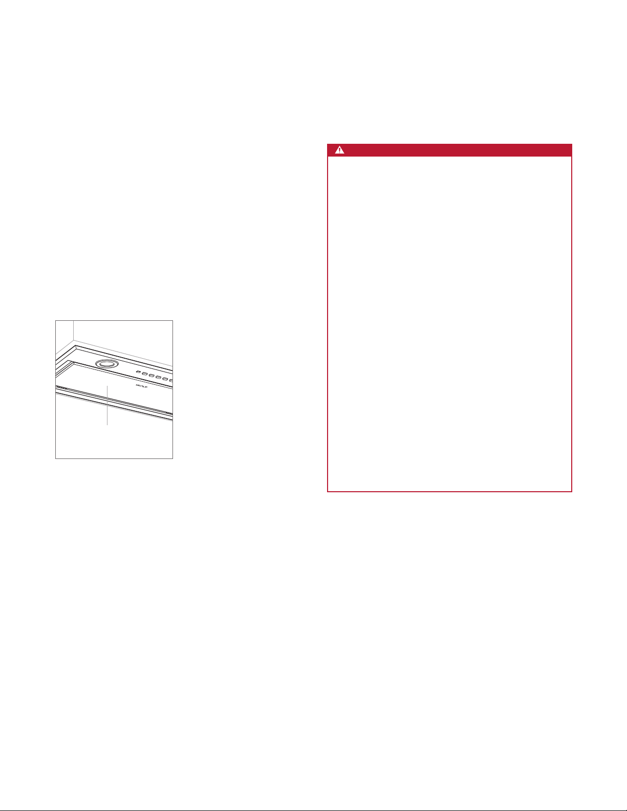
Product Information
Important product information, including the model and
serial number, are listed on the product rating plate. The
rating plate is located under the left side of the hood above
the lters (lters must be removed). Refer to the illustration
below.
If service is necessary, contact Wolf Factory Certied
Service with the model and serial number. For the name of
the nearest Wolf Factory Certied Service or for questions
regarding the installation, visit the support and service
section of our website, wolfappliance.com, or call Wolf
customer care at 800-222-7820.
RATING PLATE
(ABOVE FILTERS)
Rating plate location
IMPORTANT INSTRUCTIONS
WARNING
TO REDUCE THE RISK OF FIRE, ELECTRIC
SHOCK, OR INJURY TO PERSONS, OBSERVE
THE FOLLOWING:
a) Installation work and electrical wiring must be
done by qualied person(s) in accordance with
all applicable codes and standards, including
re-rated construction.
b) Sufcient air is needed for proper combus-
tion and exhausting of gases through the ue
(chimney) of fuel burning equipment to prevent
back drafting. Follow the heating equipment
manufacturer’s guideline and safety standards
such as those published by the National Fire
Protection Association (NFPA), and the American Society for Heating, Refrigeration and Air
Conditioning Engineers (ASHRAE), and the
local code authorities.
c) When cutting or drilling into wall or ceiling, do
not damage electrical wiring and other hidden
utilities.
d) Ducted fans must always be vented to the
outdoors.
wolfappliance.com | 3
SITE PREPARATION
Ducting
WARNING
Use only rigid metal ducting.
Consult a qualied HVAC professional for specic installation and ducting applications.
The hood accommodates a 6"
(152) round duct.
A straight, short duct run is most effective and will ensure
proper performance.
Use sheet metal screws and aluminum tape or high temperature duct tape to seal joints between ducting sections.
The hood includes a backdraft damper. Local codes may
require the use of an additional backdraft and/or make-up
air damper. Contact your local HVAC professional for specic requirements.
A make-up air damper is available through an authorized
Wolf dealer.
CAUTION
To reduce the risk of re and to properly exhaust air,
duct air outside. Do not vent exhaust air into spaces
within walls, ceilings, attics, crawl spaces, or garages.
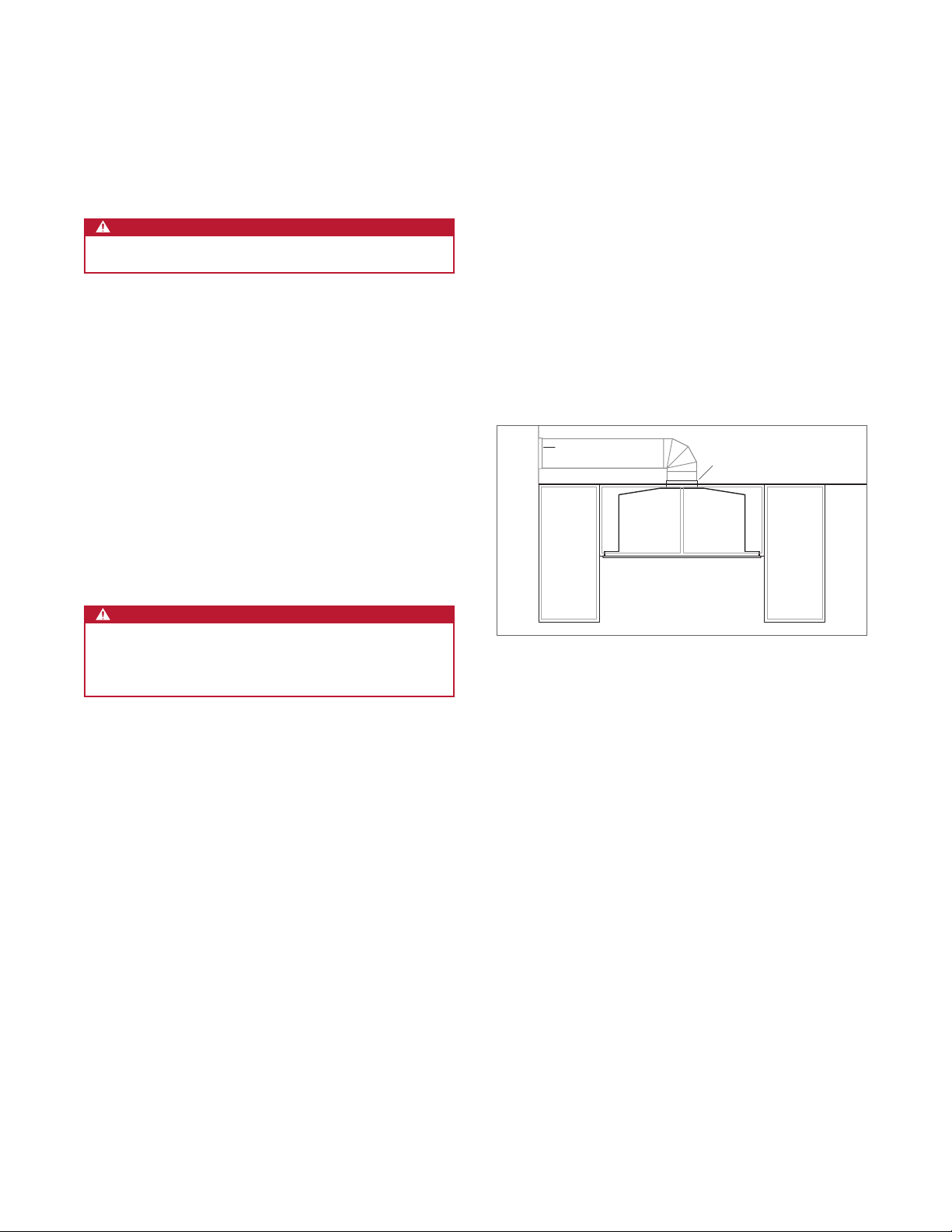
RECIRCULATION APPLICATION
The hood can be installed in a recirculation application.
Refer to the illustration below.
A vent cover is provided with the hood. Ductwork is not
provided.
Recirculating lters, available through an authorized Wolf
dealer, are required.
HORIZONTAL
DISCHARGE
Recirculation application
DISCHARGE
ABOVE CABINET
4 | Wolf Customer Care 800.222.7820
SPECIFICATIONS
Installation Requirements
Install the hood 24" (610) to 36" (914) from the bottom of the
hood to the countertop.
The hood requires a 300 or 600 CFM internal blower, available through an authorized Wolf dealer.
Consult a qualied HVAC professional for specic installation and ducting applications.
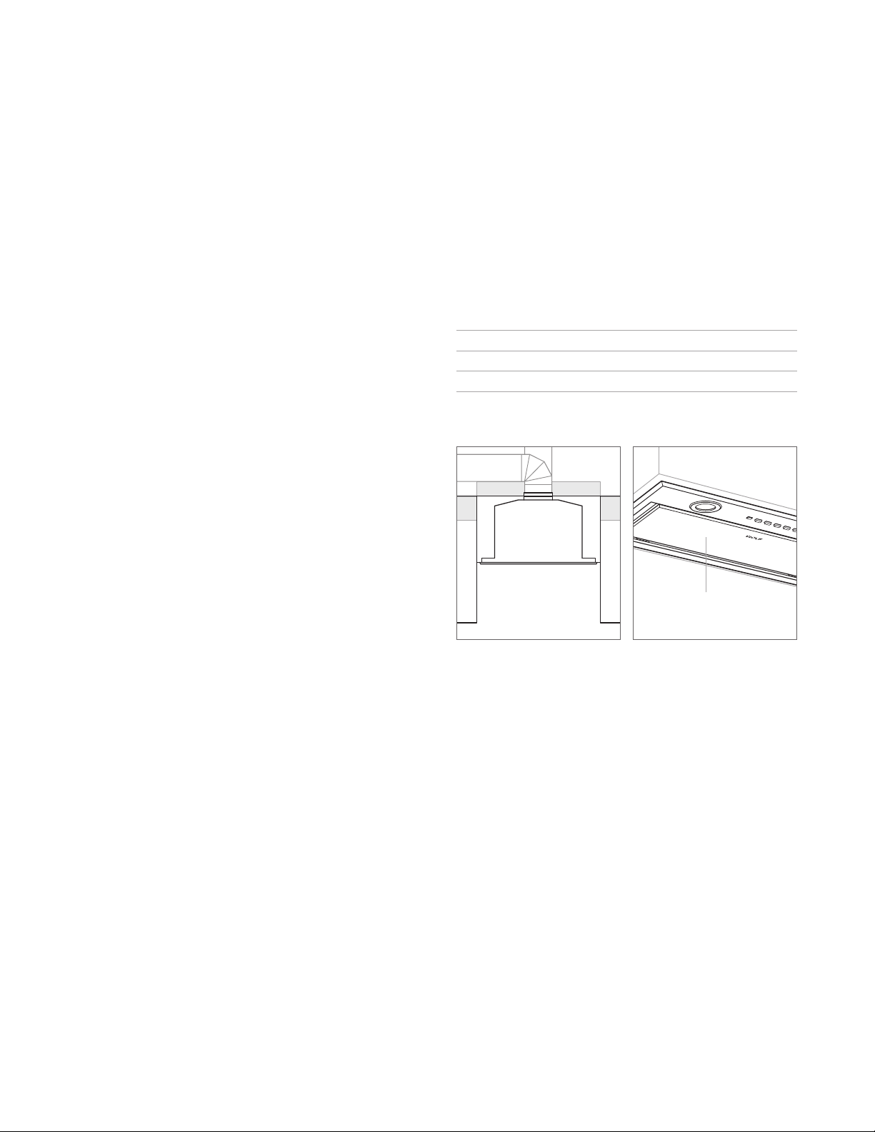
Electrical Requirements
Installation must comply with all applicable electrical codes.
Locate the electrical supply above or in an adjacent cabinet
within reach of the power cord. Refer to the illustration
below. A separate circuit servicing only this appliance is
required.
ELECTRICAL REQUIREMENTS
Electrical Supply grounded, 120 VAC, 60 Hz
Service 15 amp dedicated circuit
Power Cord 4'
EE
(1.2 m)
24" (610) TO 36" (914)
BOTTOM EDGE TO
COUNTERTOP
Electrical location
RATING PLATE
(ABOVE FILTERS)
Rating plate location
wolfappliance.com | 5
SPECIFICATIONS
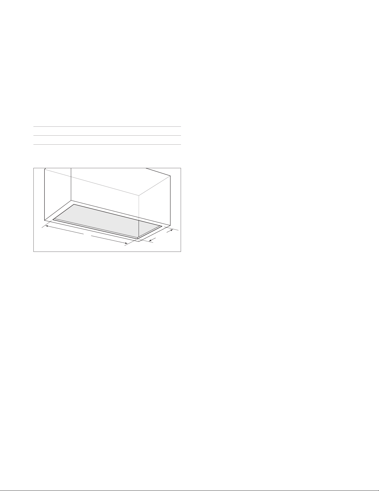
Cabinet Preparation
Refer to the chart and illustration below for opening dimensions. The cabinet must be able to support a minimum of
(45 kg).
100 lb
OPENING WIDTH
24" Hood Insert 191/2" (495)
30" Hood Insert 265/8" (676)
W
101/4"
(
260
)
Opening dimensions
W
6 | Wolf Customer Care 800.222.7820
INSTALLATION
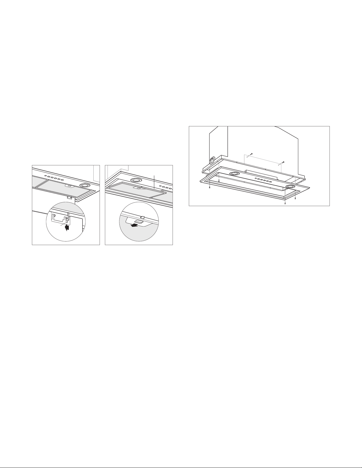
Hood Preparation
BOTTOM PANEL REMOVAL
To remove the bottom panel, refer to the illustration below.
FILTER REMOVAL
To remove the grease lters, refer to the illustration below.
IMPORTANT NOTE: Do not operate the ventilation hood
without the grease lters.
FILTER
TAB
Bottom panel removal
Filter removal
DETACH BOTTOM ASSEMBLY
Remove six screws from the hood and detach the bottom
assembly from the hood. Refer to the illustration below.
Detach bottom assembly
wolfappliance.com | 7
INSTALLATION
Hood Preparation
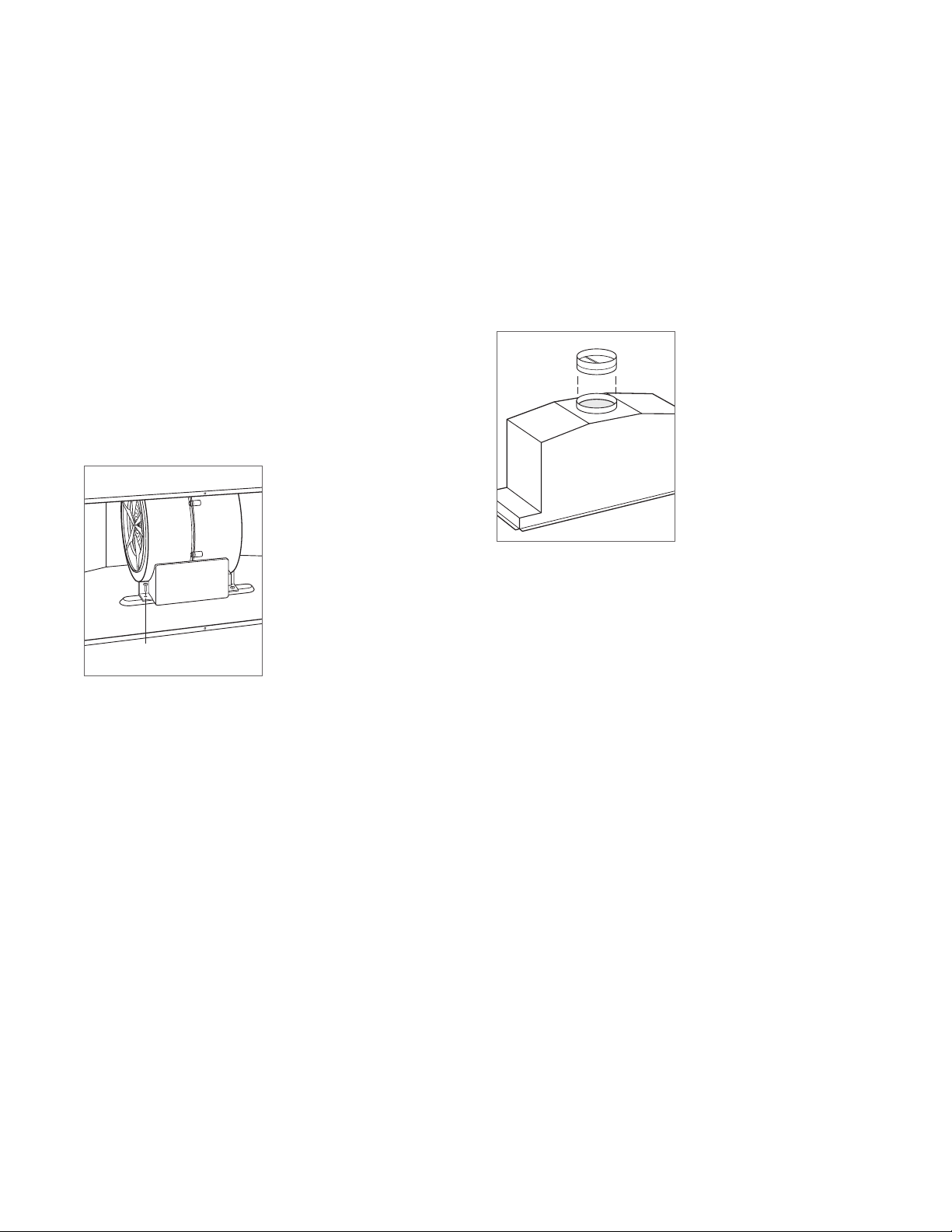
BLOWER INSTALLATION
IMPORTANT NOTE: The blower must be installed and
plugged in prior to making the electrical connection to the
hood.
1 Insert the blower by aligning the round discharge on the
blower with the discharge on the hood.
2 Secure the blower to the hood using the two mounting
screws provided with the blower. Refer to the illustration
below.
MOUNTING
SCREW
Blower installation
DAMPER INSTALLATION
Place the round damper on the round discharge and secure
with duct sealing tape. Refer to the illustration below.
Damper installation
8 | Wolf Customer Care 800.222.7820
INSTALLATION
SCREW
Installation
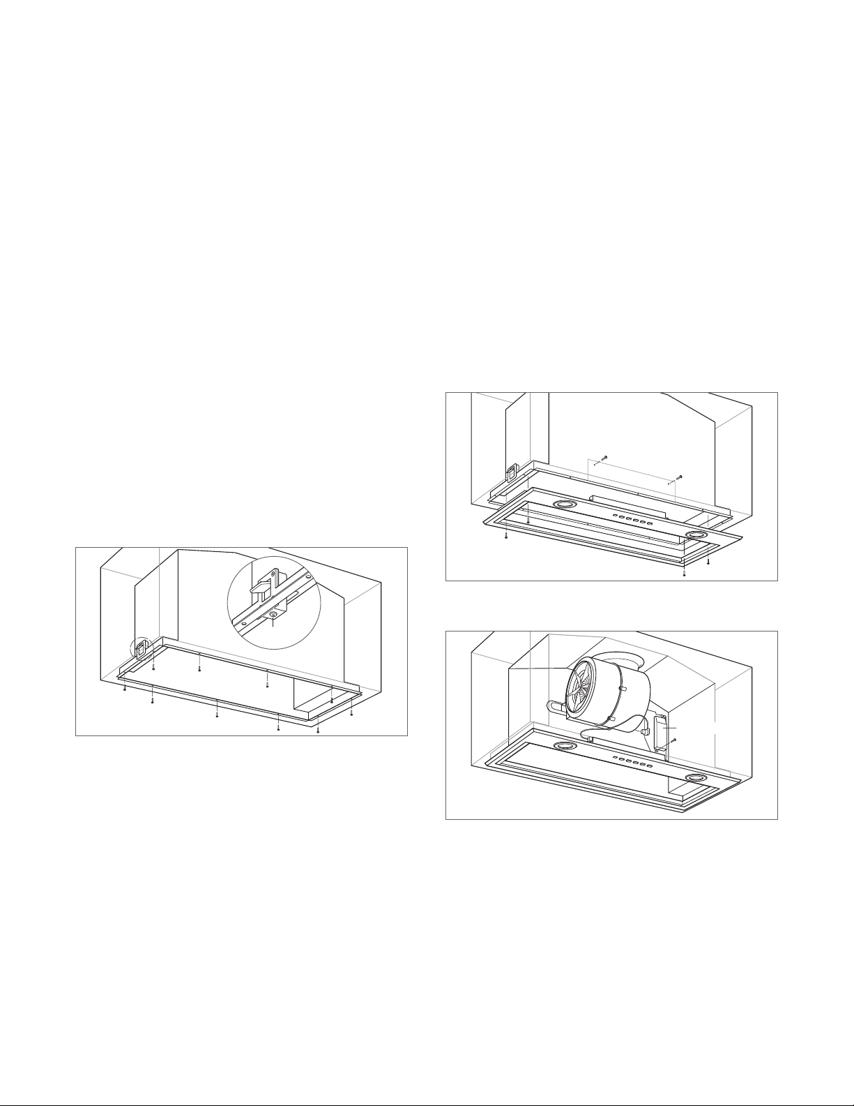
HOOD INSTALLATION
1 Insert the power cord above or into an adjacent cabinet.
Place the hood and the bottom assembly on a protected
work surface under the cabinet opening. NOTE: The
electrical connection to the bottom assembly will remain
attached during the installation.
2 Insert the hood into the opening. The support brackets
will temporarily support the weight of the hood. If the
bottom of the enclosure is too thick to engage the
brackets, the hood must be supported until the mounting
screws are installed.
3 Turn the support bracket screws clockwise to draw the
hood ange to the bottom of the enclosure. Refer to the
illustration below.
4 Secure the hood ange to the enclosure using the
mounting screws provided.
5 Press the bottom hood assembly against the bottom
hood ange and secure with the six screws. Refer to the
illustration below.
6 Insert the blower plug into the blower receptacle. Refer
to the illustration below.
7 Insert the two tabs on the top of the transformer behind
the two tabs on the hood and secure the bottom of the
transformer with one screw.
Install bottom hood assembly
Hood installation
TRANSFORMER
Hood connections
wolfappliance.com | 9
INSTALLATION
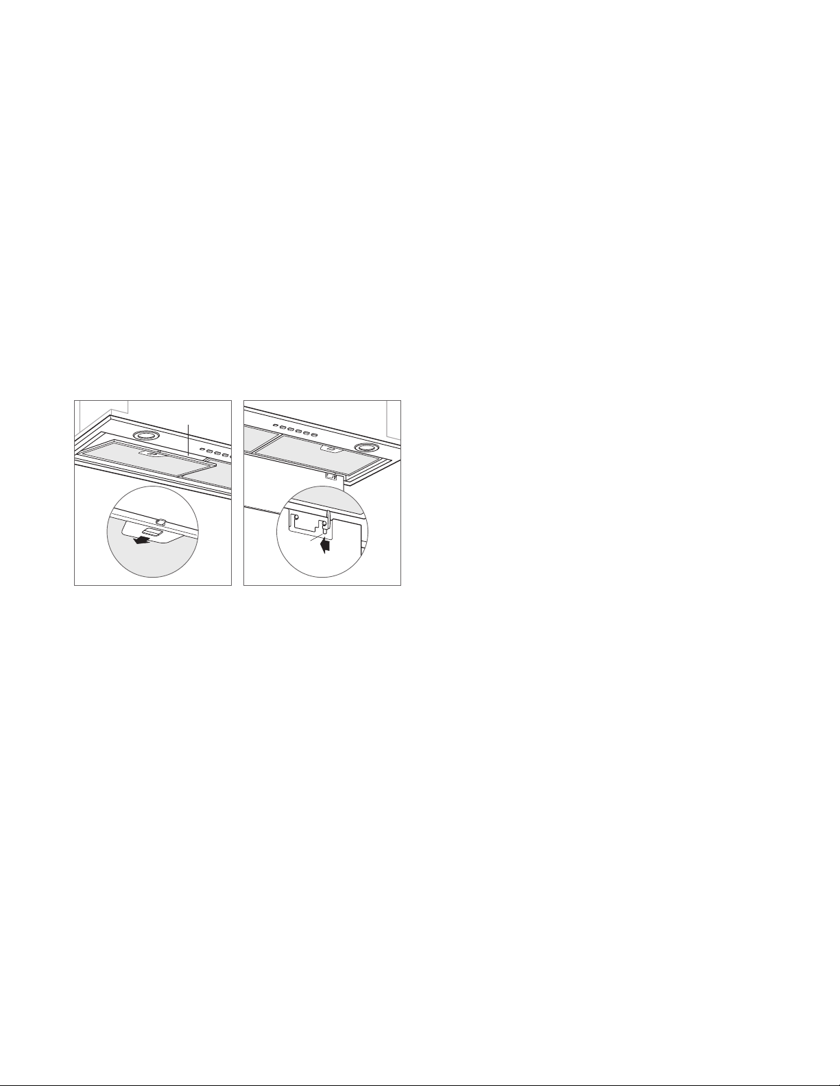
Installation
COMPLETION
1 Connect the ductwork to the damper and secure with
duct sealing tape.
2 Plug the power cord into the receptacle.
3 Turn on the electrical supply at the circuit panel and
verify operation.
4 Install the grease lters and bottom panel. Refer to the
illustrations below.
FILTER
Filter installation
TAB
Bottom panel installation
10 | Wolf Customer Care 800.222.7820
 Loading...