


VACUUM SEAL DRAWER
INSTALLATION GUIDE
SPECIFICATIONS, INSTALLATION, AND MORE
VACUUM SEAL DRAWER
Contents
2 Vacuum Seal Drawer
3 Specications
6 Installation
7 Troubleshooting
Features and specications are subject to change at any
time without notice. Visit wolfappliance.com/specs for the
most up-to-date information.
Important Note
To ensure this product is installed and operated as safely
and efciently as possible, take note of the following types
of highlighted information throughout this guide:
IMPORTANT NOTE highlights information that is especially
important.
CAUTION indicates a situation where minor injury or product
damage may occur if instructions are not followed.
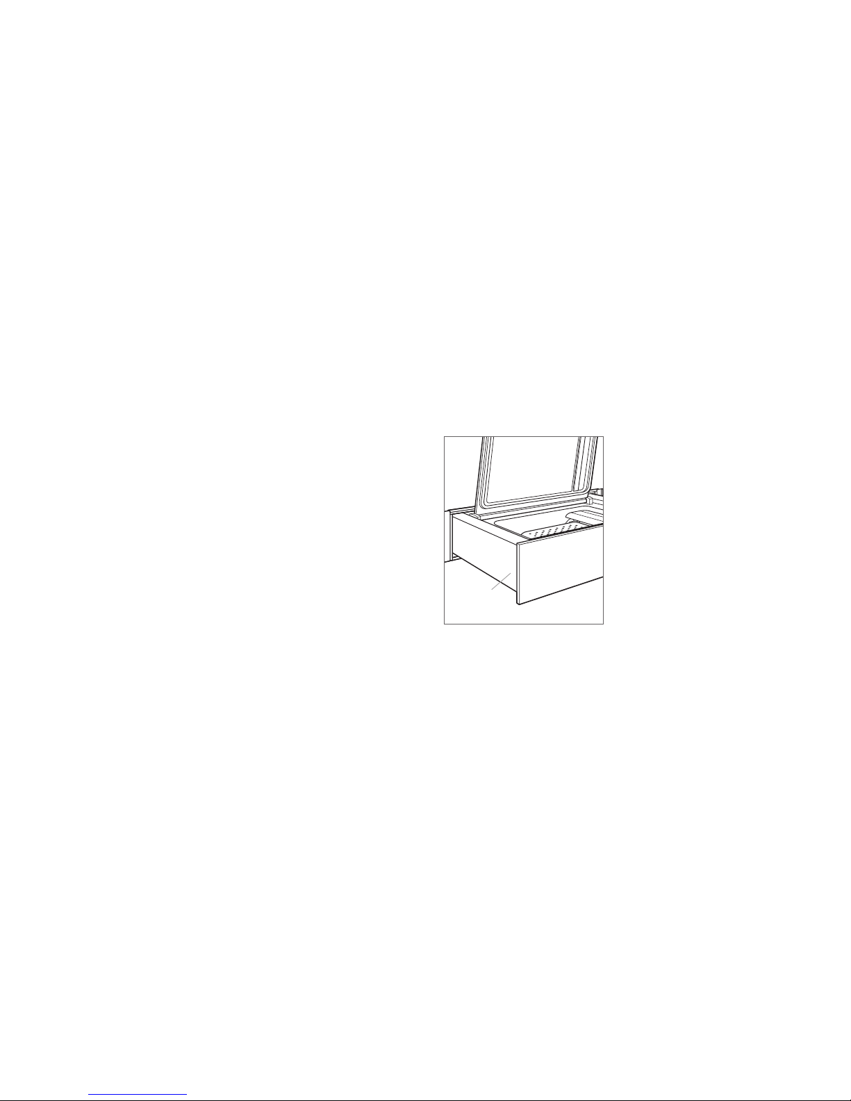
Product Information
Important product information, including the model and
serial number, are listed on the product rating plate. The
rating plate is located on the left side of the drawer. The
drawer must be open and the lid lifted to view the rating
plate. Refer to the illustration below.
If service is necessary, contact Wolf Factory Certied
Service with the model and serial number. For the name of
the nearest Wolf Factory Certied Service or for questions
regarding the installation, visit the contact and support
section of our website, wolfappliance.com, or call Wolf
Customer Care at 800-222-7820.
WARNING states a hazard that may cause serious injury or
death if precautions are not followed.
IMPORTANT NOTE: Throughout this guide, dimensions in
parentheses are millimeters unless otherwise specied.
IMPORTANT NOTE: Save these instructions for the local
electrical inspector.
SAVE THESE INSTRUCTIONS
RATING
PLATE
Rating plate location
2 | Wolf Customer Care 800.222.7820
SPECIFICATIONS
Installation Requirements
The vacuum seal drawer can be installed in a standard or
ush inset application. Finish the edges of the opening.
They may be visible when the drawer is open.
For standard installations, the face trim overlaps stiles and
rails. Refer to the chart below.
1
For ush inset installations, a minimum
required on all sides. To ensure consistent reveals, each
corner of the opening must be exactly 90°.
An anti-tip block must be installed to prevent the vacuum
seal drawer from tipping forward when opened.
INSTALLATION REQUIREMENTS
BASE SUPPORT MIN
Vacuum Seal Drawer 75 lb (34 kg)
TRIM OVERLAP
Top 0" (0)
Bottom 0" (0)
Sides
/8" (3) reveal is
11
/16" (18)
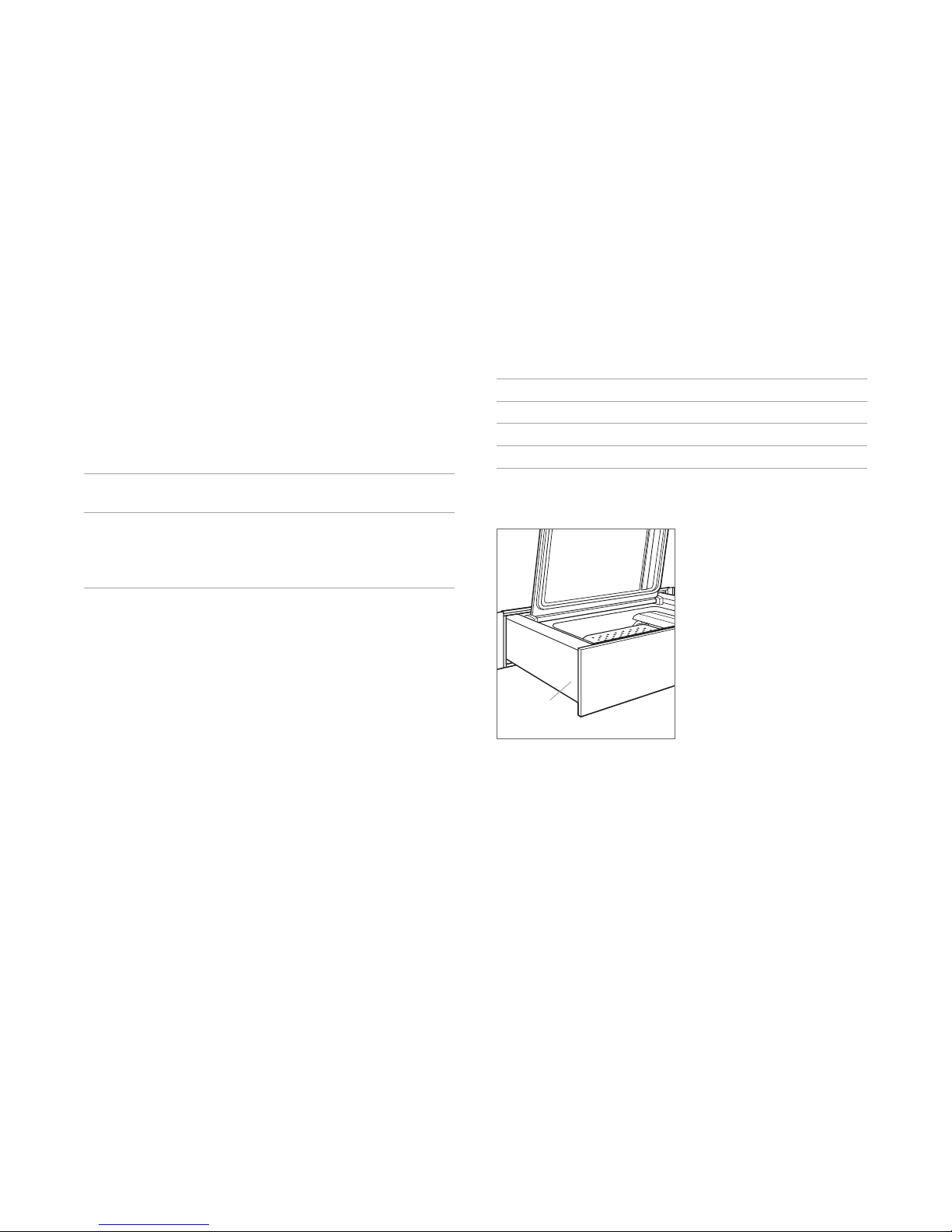
Electrical Requirements
Installation must comply with all applicable electrical codes.
Locate the electrical supply as shown in the illustrations
on the following pages. A separate circuit servicing only
this appliance is required. A ground fault circuit interrupter
(GFCI) is not recommended and may cause interruption of
operation.
ELECTRICAL REQUIREMENTS
Electrical Supply grounded, 120 VAC, 60 Hz
Service 10 amp dedicated circuit
Receptacle 3-prong grounding-type
Power Cord 3'
(.9 m)
RATING
PLATE
Rating plate location
wolfappliance.com | 3
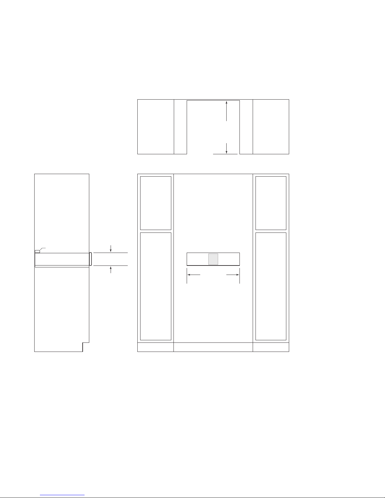
SPECIFICATIONS
SIDE
Vacuum Seal Drawer
STANDARD INSTALLATION
OPENING
TOP VIEW
221/2"
(572)
DEPTH
ANTI-TIP BLOCK
VIEW
(141)
59/16"
OPENING HEIGHT
E
221/8" (562)
OPENING WIDTH
FRONT VIEW
4 | Wolf Customer Care 800.222.7820
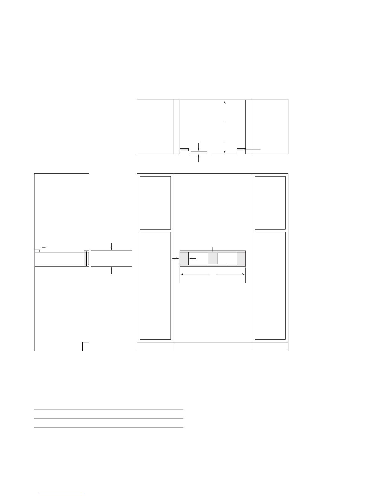
SPECIFICATIONS
SIDE
*W
**
***
Vacuum Seal Drawer
FLUSH INSET INSTALLATION
7
/8" (22)**
231/2" (597)
TOP VIEW
FLUSH
INSET
DEPTH
FINISHED
CLEATS*
ANTI-TIP BLOCK
53/4" (146)
FLUSH INSET
VIEW
ill be visible and should be finished to match cabinetry.
Cleat depth assumes a stainless steel, black glass, or 3/4" (19) custom panel.
Dimension provides minimum reveals.
FLUSH INSET WIDTH
24" Opening 233/4" (603)
HEIGHT***
W A
13
/16" (21)
30" Opening 301/8" (765) 4" (102)
1
/16" (2)
A
FLUSH INSET WIDTH***
E
W
FRONT VIEW
1
/8" (3)
wolfappliance.com | 5
INSTALLATION
Preparation
Remove and recycle packing materials. Do not discard the
package containing the two screws provided for installation.
Install an anti-tip block against the rear cabinet wall. Verify
the screws are adequately secured and do not penetrate
electrical wiring or plumbing.
IMPORTANT NOTE: The installation hardware is provided
with the accessory front panel.
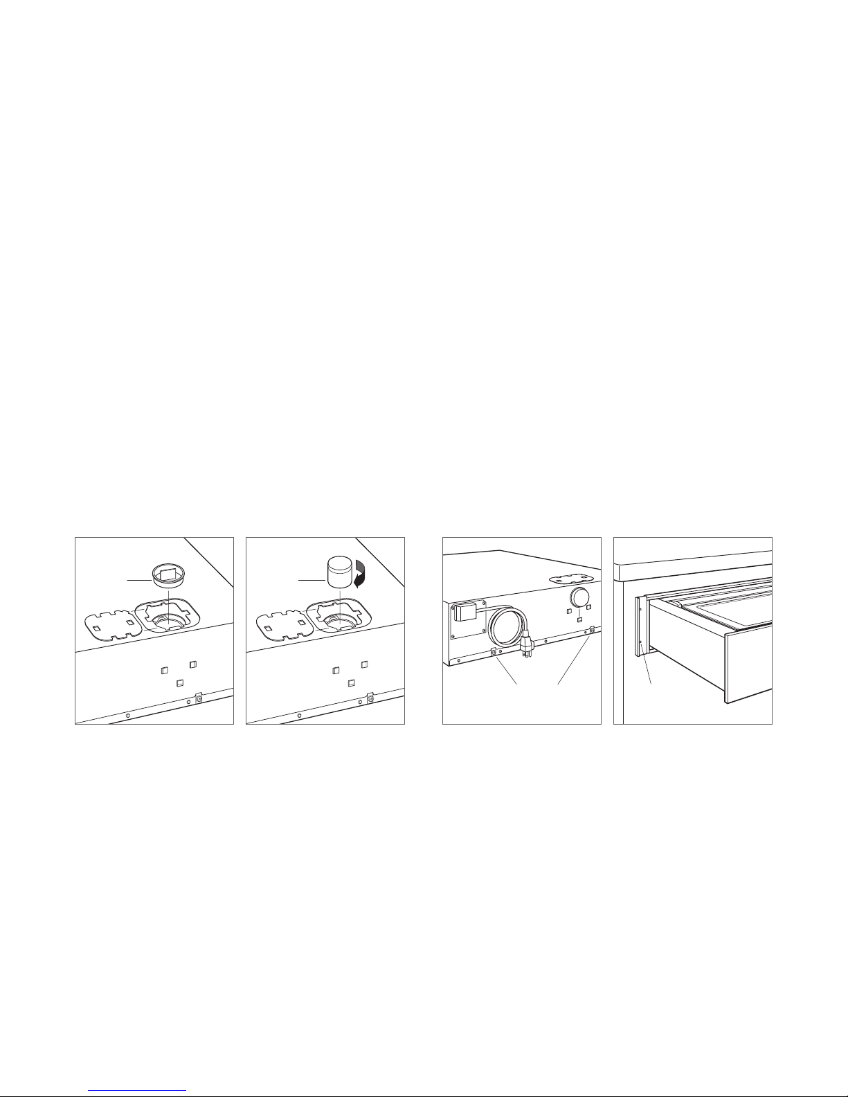
Installation
1 Place the unit on a protected work surface.
2 Slide the lter cover to the side and remove the plug.
Refer to the illustration below.
3 Insert the lter and rotate clockwise. Refer to the illustra-
tion below.
PLUG FILTER
4 Slide the cover over the lter.
5 Place the plug on the back of unit and remove the two
shipping screws. Refer to the illustration below.
6 Install the side trim. Refer to the installation instructions
provided with the accessory front panel.
7 Place the unit near the opening and plug the power cord
into the receptacle.
8 Slide the unit into the opening.
9 Open the drawer to full extension.
10 Drill a pilot hole in each mounting hole location. Refer
to the illustration below.
11 Secure the unit with the screws provided.
12 Turn on the electrical supply to the outlet and verify
operation.
Plug removal
Filter installation
6 | Wolf Customer Care 800.222.7820
SHIPPING
SCREWS
Shipping screw location
MOUNTING
HOLE
Mounting hole location
 Loading...