

Instruction Manual
Ultrasound Generator
GA--A 181 /en/ Index: 09--05--5.0 / ÄM: KG 04--252
2271
Important general instructions for use
Ensurethatthisproduct isonlyusedas intendedanddescribedin theinstructionmanual,by adequately trained and qualified personnel, and that maintenance and repair is only carried out by
authorized specialized technicians.
Operate this product onlyinthe combinations and with the accessoriesandspare parts listed in
the instruction manual. Use othercombinations, accessories and wearing parts only if theyare
expressly intended for this use and if the performance and safety requirements are met.
Reprocesstheproductsbefore every applicationandbeforereturning them forrepairasrequired
by the instruction manual inorder to protect the patient, user or third parties.
Subject to technical changes!
Due to continuous development of our products, illustrations and technical data may deviate
slightly from the data inthis manual.
CAUTION -- USA only:
Federallawrestrictsthis unittobeused orsold,exceptunder the supervisionofamedical doctor.
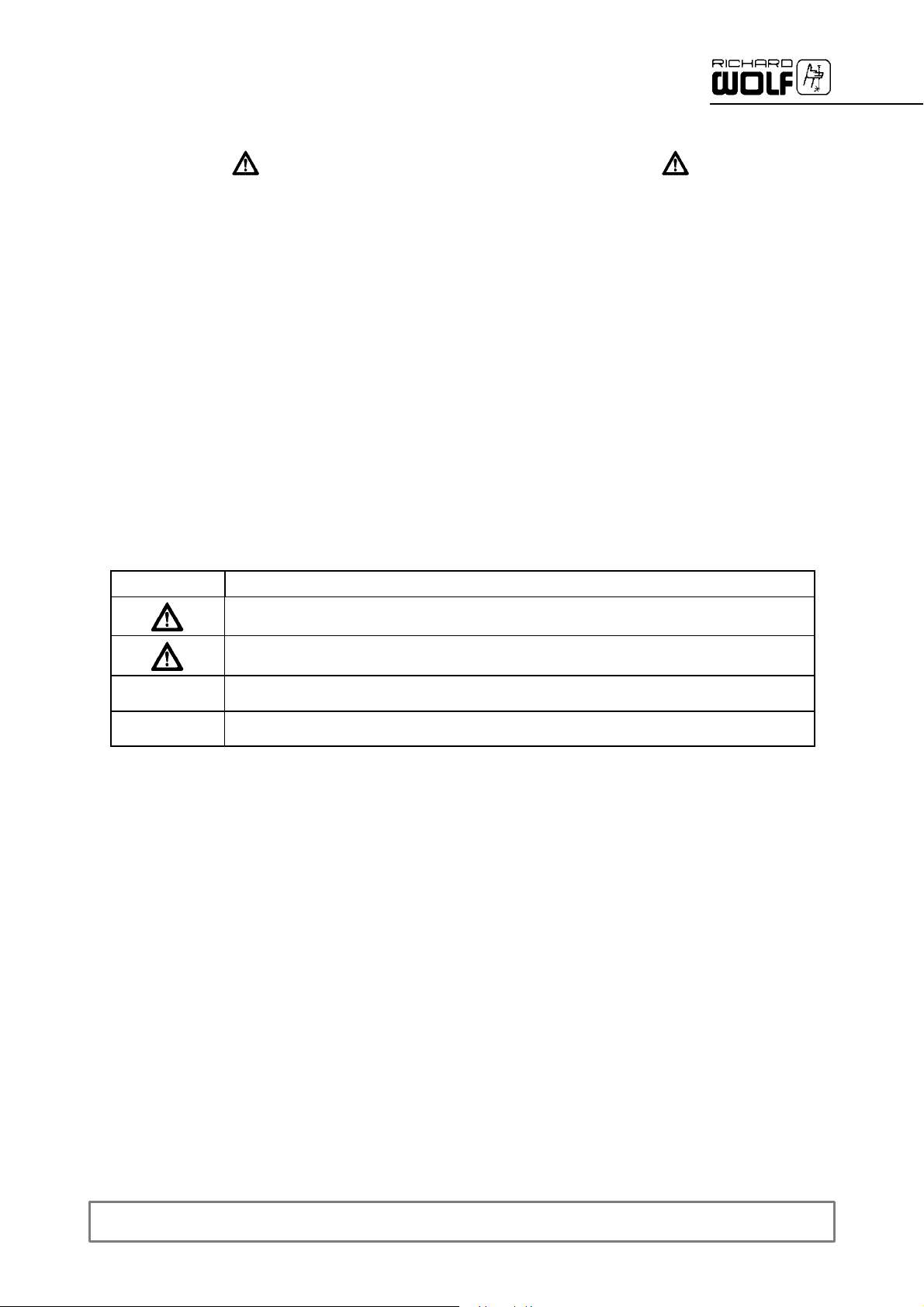
Safety instructions and levels of danger
Symbol Level of danger
WARNING!
Failure to observe can result in death or severe injury.
CAUTION!
Failure to observe can result in slight injury or damage to the product.
.
.
IMPORTANT!
Failure to observe can result in damage to the product or surrounding.
NOTE!
Tips for optimum use and other useful information.
GERMANY
RICHARD WOLF GmbH
D--75438 Knittlingen
Pforzheimerstr. 32
Tel.:(..49)--(0)7043--35--0
Fax:(..49)--(0)7043--35300
MANUFACTURER
E--mail: info@richard--wolf.com
Internet: www.richard--wolf.com
BELGIUM
N.V. Endoscopie
RICHARD WOLF Belgium S.A.
Industriezone Drongen
Landegemstraat 6
B--9031 Gent --Drongen
Tel.: +329.280.81.00
Fax:+329.282.92.16
E--mail: endoscopy@richard--wolf.be
0
USA
RICHARD WOLF
Medical Instruments Corp.
353 Corporate Woods Parkway
Vernon Hills, Illinois 60061
Tel.: 847--913 1113
Fax:847--913 1488
E--mail: sales&marketing@richardwolfusa.com
Internet: www.richardwolfusa.com
FRANCE
RICHARD WOLF France S.A.R.L.
Rue Daniel Berger
Z.A.C. La Neuvillette
F--51100 Reims
Tel.: +333.26.87.02.89
Fax:+333.26.87.60.33
E--mail: endoscopes@richardwolf.fr
UK
RICHARD WOLF UK Ltd.
Waterside Way
Wimbledon
SW 17 0HB
Tel.: 020--8944 7447
Fax:020--8944 1311
E--mail: admin@richardwolf.uk.com
Internet: www.richardwolf.uk.com
AUSTRIA
RICHARD WOLF Austria
Ges.m.b.H.
Wilhelminenstraße 93 a
A--1160 Wien
Tel.: +431-- 405 51 51
Fax:+431-- 405 51 51--45
E--mail: info@richard--wolf.at
Internet: www.richard--wolf.at
GA--A 181

Contents
1 General information 1.......................................................
1.1 Symbols 1..................................................................
1.2 Intended use 2..............................................................
1.2.1 Contraindications 2...........................................................
1.3 Combinations 2..............................................................
1.3.1 Device combinations 2........................................................
1.3.2 General requirements on products/components of a combination 3.................
1.3.3 Specific requirements on the products/components of a combination 4..............
1.4 Electromagnetic compatibility (EMC) 4..........................................
2 Illustration 6................................................................
2.1 Front panel 6................................................................
2.1.1 Legend 6...................................................................
2.2 Rear panel 7................................................................
2.2.1 Legend 7...................................................................
3Setup 8....................................................................
3.1 Preparation when using Suction Pump 2207 9...................................
3.1.1 Ultrasound Generator with “Suction Pump 2207” 9................................
3.1.2 Legend 9...................................................................
3.1.3 Rear panel connectors 10......................................................
3.1.4 Front panel connectors 10......................................................
4 Checks 11...................................................................
4.1 Visual check 11...............................................................
4.2 Functional checks 1 1..........................................................
4.2.1 Ultrasound generator and transducer 1 1..........................................
4.2.2 Ultrasound Generator and Suction Pump 12......................................
5Use 13......................................................................
5.1 Operating principle of Ultrasound Generator 13...................................
5.2 Operating principle of ultrasound lithotripsy 13....................................
5.3 Operation of Ultrasound Generator 14...........................................
5.3.1 Controls and indicators of Ultrasound Generator 2271 (US--LITHO) 15...............
5.3.2 Ultrasound Generator ON/OFF 15...............................................
5.3.3 “Intensity” preselection (power stage) 16.........................................
5.3.4 Activation of transducer 16.....................................................
5.3.5 ”Transducer malfunction” warning lamp 16........................................
5.3.6 ”Generator malfunction” alarm lamp 16...........................................
5.4 Changing the sonotrode 17.....................................................
5.4.1 Checking the sonotrodes 17....................................................
5.4.2 Changing the sonotrodes 18....................................................
6 Operation in the RIWO NET SYSTEM 19.......................................
6.1 Combination with RIWO NET SYSTEM 19.......................................
6.2 Operation 19.................................................................
6.3 Connection to the RIWO NET SYSTEM 20.......................................
6.4 Controlling the devices using the RIWO--NET menu 21.............................
6.4.1 Controlling the devices via the different input media 21.............................
6.4.2 Illustration of menu 21.........................................................
GA--A 181
I

6.4.3 Main menu 22................................................................
6.4.4 Ultrasound output function 22...................................................
6.5 System messages 22..........................................................
6.5.1 Operating instructions 22.......................................................
6.5.2 Warnings 22..................................................................
6.5.3 Error messages 22............................................................
7 Reprocessing and maintenance 23............................................
7.1 Reprocessing of device 23.....................................................
7.2 Reprocessing of accessories 24.................................................
7.2.1 Wet preparation at the point of use 24...........................................
7.2.2 Disassembly before cleaning 24.................................................
7.2.3 Manual cleaning 25............................................................
7.2.4 Machine cleaning 25...........................................................
7.2.5 Disinfection 26................................................................
7.2.6 Steam sterilization 26..........................................................
7.2.7 Assembly 26.................................................................
7.2.8 Reprocessing of foot switch 26..................................................
7.3 Maintenance of device and accessories 27.......................................
7.4 Maintenance 27...............................................................
7.4.1 Maintenance intervals 27.......................................................
7.5 Quarterly check 27............................................................
7.5.1 Measuring devices and auxiliary means for checking 27............................
7.5.2 Visual check 28...............................................................
7.5.3 Functional checks 28..........................................................
7.6 Technical safety check 29......................................................
8 Technical description 30.....................................................
8.1 Trouble shooting 30...........................................................
8.1.1 Device faults 30...............................................................
8.2 Technical data 31.............................................................
8.2.1 Electrical connection 31........................................................
8.2.2 Technical data of ultrasound generator 31........................................
8.2.3 Interfaces of ultrasound generator 31............................................
8.2.4 Technical data of transducer (2271.501) 32.......................................
8.2.5 Technical data of footswitch (2030.12) 32.........................................
8.3 Operating, storage, transport and shipping conditions 32...........................
8.4 Spare parts and accessories 33.................................................
8.5 Replacing parts 34............................................................
8.5.1 Device fuses 34...............................................................
8.5.2 Disposal of the product, packing material and accessories 34.......................
9 Literature 35.................................................................
II
GA--A 181
1 General information
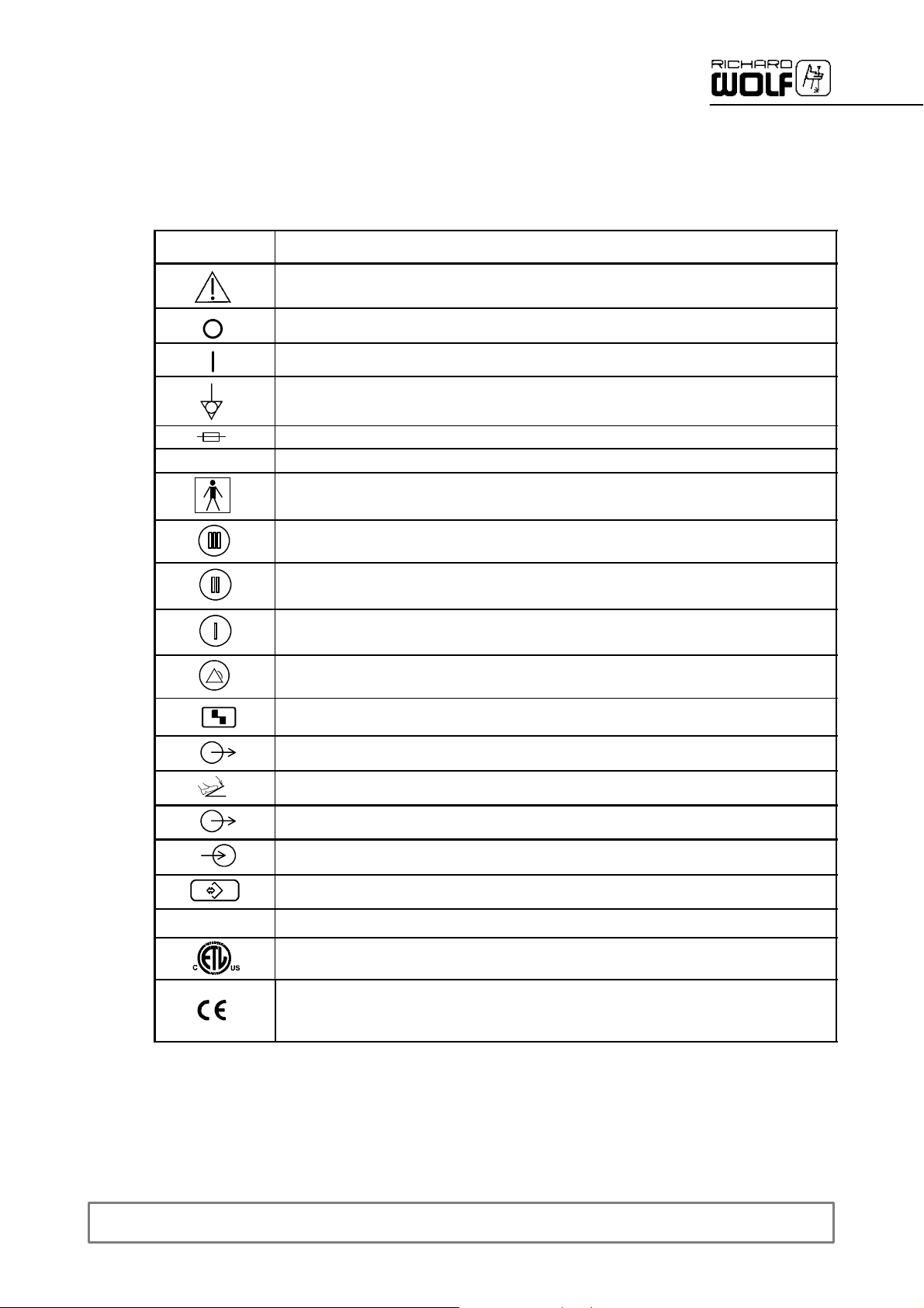
1.1 Symbols
Symbols
µ
Meaning
Attention,consultACCOMPANYING DOCUMENTS
Off(disconnection from mains/power)
On (connection to mains/power)
Equipotentality
Fuse
Alternating current(AC)
TYPE BF APPLIED PART
Intensity preselection, stage III
Intensity preselection, stage II
Intensity preselection, stage I
Fault indicator“Generator malfunction” warning lamp
REF
Fault indicator”Transducer malfunction” warning lamp
Standby indicator, “Device output active” lamp (foot switch actuated)
Socket for foot switch
Interfacesymbol/device output(e.g.RIWONET SYSTEM)
Interfacesymbol/device input(e.g.RIWO NET SYSTEM)
Socket, 4--pole, control output (Suction Pump)
Order number
A Registered Trademark of ETL, a Recognized Testing Laboratory, listing compliance as
Medical Electrical Equipment tostandard CAN/CSA C 22.2 No. 601.1 (c) and UL 60601--1 (us)
Identification in conformity with Medical Devices Directive 93/42/EEC only valid if the product
and/or packagingis marked with this symbol. Products of category IIa andabove, as well as
sterile products or products with measuring function of category I, are additionally marked with the
code number of thenotified body (0124).
GA--A 181
1
1.2 Intended use
1.2.1 Contraindications
The ultrasound generator (US--LITHO) 2271 with transducer and sonotrode is used in intracorporeal ultrasound lithotripsy exclusively for desintegrating kidney stones, urinary bladder stones and ureter stones under
direct endoscopic view . The use of this device for purposes other than
the above is not admissible.
CAUTION!
In therapeutic use an adequate backup unit must be available for
the unlikely event that the device fails.
Contraindications directly related to the product are presently unknown.
On the basis of the patient’s general condition the doctor in charge must
decide whether the planned use is possible or not. For further information
please refer to the current medical literature.
NOTE!
.
Before the first use we recommend reading the relevant literature (see
chapter 9 literature“).
1.3 Combinations
.
1.3.1 Device combinations
WARNING!
Danger of life-threatening embolism.
If used in combination with a peristaltic suction pump (e.g. Suction
Pump 2207) no air or liquid must be discharged from the tip of the
sonotrode. The sonotrode must be used exclusively for evacuating.
Strictly follow the instruction manual of the roller suction pump.
IMPORTANT
In addition to this instruction manual follow the manuals of the products
used in combination with this product.
The Ultrasound Lithotriptor consisting of Ultrasound Generator 2271 with
transducer and sonotrode may only be used in conjunction with a suitable
suction device, e.g. a suction pump. The R.Wolf “Suction Pump 2207” is
specially designed for use with the ultrasound generator and provides
ideal conditions for the use of this device.
If a different suction pump or suction device (different manufacturer) is
used, the operator/user must check whether the suction device features
a controllable, adjustable vacuum, which meets the requirements.
To ensure sufficient cooling of the transducer and the sonotrode, make
sure that the suction device can provide an adjustable vacuum of up to
--0.6 bar on a continuous basis.
2
GA--A 181
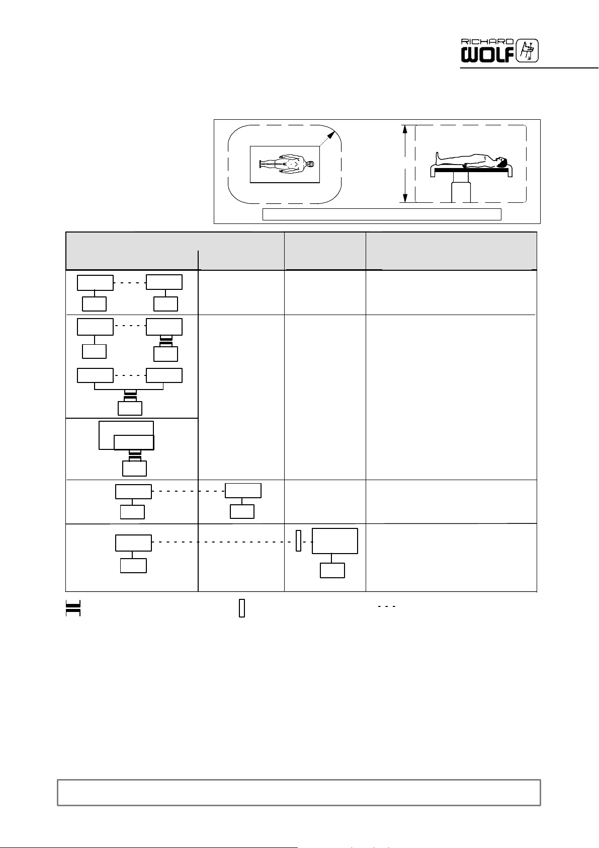
1.3.2 General requirements on products/components of a combination
The general requirements depend on whethertheproducts/components areinside or outside the patient environment.
Medically used room
Inside the patient environment
MP
µ
MP
µ
MP NMP
µ
MP
NMP
MP
µ
NMP
µ
**
Patient environment
Acc. to UL 60601--1: R = 1.83 m (6 feet) ; h = 2.29 m (71/2feet)
outside the patient
environment
--
--
R=1.5m
Non--medically
used room
--
--
Patient environment
h=2.5m
Requirements / measures
Leakage currents to clause 19
IEC/EN 60601--1--1
*
--
a) additional protective earth connection
(to be clarified with manufacturer),
or
b) with additional isolating transformer
**
µ
MP
µ
MP
µ
additional isolating transformer
according to IEC/ EN 60601--1--1 **
MP = medical electrical device according to IEC/ EN 60601--1, UL 60601--1, CSA C22.2 No. 601
NMP = non--medical electrical device in accordance with the relevant product--specific IEC/ EN/ UL/ IEC standards
* If connected via a joint mains/power cord under normal conditions the earth leakage current of the system must not exceed 500 µA
(300 µA for systems in acc.withUL 60601--1).
** e.g. Richard Wolf Video Trolley with ”isolating transformer”.
NMP
µ
additional separating device
according to IEC/ EN 60601--1--1
--
MP or
NMP
µ
--
a) common protective earth connection, or
b) additional protective earth connection
(to be clarified with manufacturer), or
c) additional separating device (to avoid
earth/ground loops inthe case of a
potential difference)
Functional
connection
µ power supply grid
GA--A 181
3
1.3.3 Specific requirements on the products/components of a combination
establishmentsandthosedirectlyconnectedtothepubliclow--voltage
IMPORTANT!
.
Persons combining products to form a system areresponsible fornot impairing thesystem’s compliance with
the performance and safety requirements, and that the technical data and the intended use are adequately
fulfilled.
Electromagnetic interference or other types ofinterference occurring between this product and other products
can cause failures or malfunctions.
When selecting the system components ensure thatthey meet the requirements for the medical environment
they are used in,inparticular IEC/ EN60601--1--1. In caseof doubt contact the manufacturer(s)of the system
components.
Do not touch connecting devicesfor electrical connections betweenthe different components (such as signal
input and output connections for video signals, data exchange,controlcircuits, etc.) and thepatientatthe
same time.
1.4 Electromagnetic compatibility (EMC)
NOTE: The device orsystem in the following called product always relates to the ultrasound generator 2271
Guidance and manufacturer’s declaration -- electromagnetic emissions
The product is intended for use in the environment specified below. The user should assure that the product is used in such an environment.
Emissions measurement/test Compliance Electromagnetic environment -- Guidance
HF emissions to CICPR 11 Group 1
HF emissions to CISPR 11 Class B
Harmonic emissions to IEC 61000--3--2 Class A
In conformity with IEC 61000--3--3 “Voltage fluctuations / flicker
emissions”
The product uses HF energy for its internal function.
The HF emission level is extremely low and it is not likely to cause any
interference in nearby electronic equipment.
The product is suitable for use in all establishments, including domestic
--
power supply network that supplies buildings used for domestic purposes.
Guidance and manufacturer’s declaration -- electromagnetic immunity
The product is intended for use in the environment specified below. The user should assure that the product is used in such an environment.
Immunity tests IEC 60601 test level Compliance Electromagnetic environment -- guidance
Electrostatic Discharge (ESD)
to IEC 61000--4--2
Electrical fast transients, bursts
to IEC 61000--4--4
Surge voltage (surges)
to IEC 61000--4--5
Voltage dips, short interruptions and
voltage variations on power supply
input lines
to IEC 61000--4--11
Power frequency (50/60 Hz) magnetic
field,
to IEC 61000--4--8
* NOTE: UTis the line/mains voltage prior to application of the test level.
± 6 KV contact
± 8KVair
± 2 KV for power supply lines
± 1 KV for input/output lines
± 1 KV differential mode
± 2KVcommonmode
Voltage dip for 0.5cycle
> 95% U
Voltage dip for 5cycles
> 60% U
Voltage dip for 25cycles
> 30% U
Voltage dip for 5 sec
> 95% U
3A/m Yes
*
T
*
T
*
T
*
T
Yes
Yes
Yes
Yes
Floors should wood, concrete or ceramic tile.
If the floors are covered with synthetic material, the
releative humidity should be at least 30%.
Mains/line power quality should be that of a typical
commercial or hospital environment.
Mains/line power quality should be that of a typical
commercial or hospital environment.
Mains/line power quality should be that of a typical
commercial or hospital environment. If the user of
the product requires continued operation during
power mains/line interruptions it is recommended
that the product be powered from an uninterruptible
power supply orbattery.
Power frequency magnetic fields should be at
levels characteristic of a typical location in a
commercial or hospital environment.
4
GA--A 181
Guidance and manufacturer’s declaration -- electromagnetic immunity for products that are not life --supporting
The product is intended for use in the environment specified below. The user should assure that the product is used in such an environment.
Immunity test IEC 60601 test levels
Conducted HF interference
to IEC 61000--4--6
Radiated HF interference
to IEC 61000--4--3
REMARKS: At 80 MHz and 800 MHz the higher frequency range applies.
These guidelines may no apply in all situations, as the propagation of electromagnetic waves is affected by absorption and
reflexion from buildings, objects and people.
1 = The field strength of fixed transmitters (e.g. base stations for radio telephones, land mobile radios, amateur radio, radio broadcast and
TV broadcast, ...), cannot be predicted theoretically with accuracy. To assess the EMC environment due to fixed transmitters an
electromagnetic site survey should be conducted. If the measured field strength in the location in which the product is used exceeds
the applicable compliance level above, the product should be observed to verify normal operation.
If abnormal performance is observed, additional measures may be required, such as reorienting or relocating the product.
2 = Over the frequency range between 150 kHz and 80 MHz the field strength should be below 3 V/m.
3V
rms
150kHz to 80 MHz
3V/m
80 MHz to 2.5 GHz
Compliance
level
Yes
Electromagnetic environment -- guidance
Portable and mobile RF communications equipment should be
used no closer to any part of the product, including cables,
than the recommended separation distance calculated from
equation applicable to the frequency of the transmitter.
Recommended separation distance:
d=1.2p P
d=1.2p P for 80 MHz to 800 MHz
d=2.3p P for 800 MHz to 2.5 GHz
P = Nominal power output rating of the transmitter in watts (W)
(according to the transmitter manufacturer)
d = recommended separation distance in meters (m)
Field strengths from fixed RF transmitters, as determined by
an electromagnetic site survey
compliance level in each frequency range
Interference may occur in the vicinity of devices with the
following symbol:
1
, should beless than the
2
.
The recommended separation distances between portable and mobile HF telecommunication devices and
devices which are notlife-- supporting
The product is intended for use in an electromagnetic environment with HF disturbances are controlled.
The user can help prevent electromagnetic interference by maintaining a minimum distance between portable and mobile
HF telecommunications equipment and the product.
Rated nominaloutput power of the
transmitter(Watts)
0.01 0.12 0.12 0.23
0.1 0.38 0.38 0.73
1 1.2 1.2 2.3
10 3.8 3.8 7.3
100 12 12 23
For transmitters rated at a nominal output power not listed in the table above, the recommended separation distance (d) in meters (m) can
be determined using the applicable equation (observe frequency). P = nominal power of the transmitter in Watts (W).
REMARKS: At 80 MHz and 800 MHz the higher frequency range applies.
These guidelines may no apply in all situations. Electromagnetic propagation is affected by absorption and reflexion
from buildings, objects and people.
150 kHz to 80 MHz
d=1.2p P
Separation distance as a function of transmitter frequency (m)
80 MHz to 800 MHz
d=1.2p P
800 MHz to 2.5 GHz
d=2.3p P
GA--A 181
5
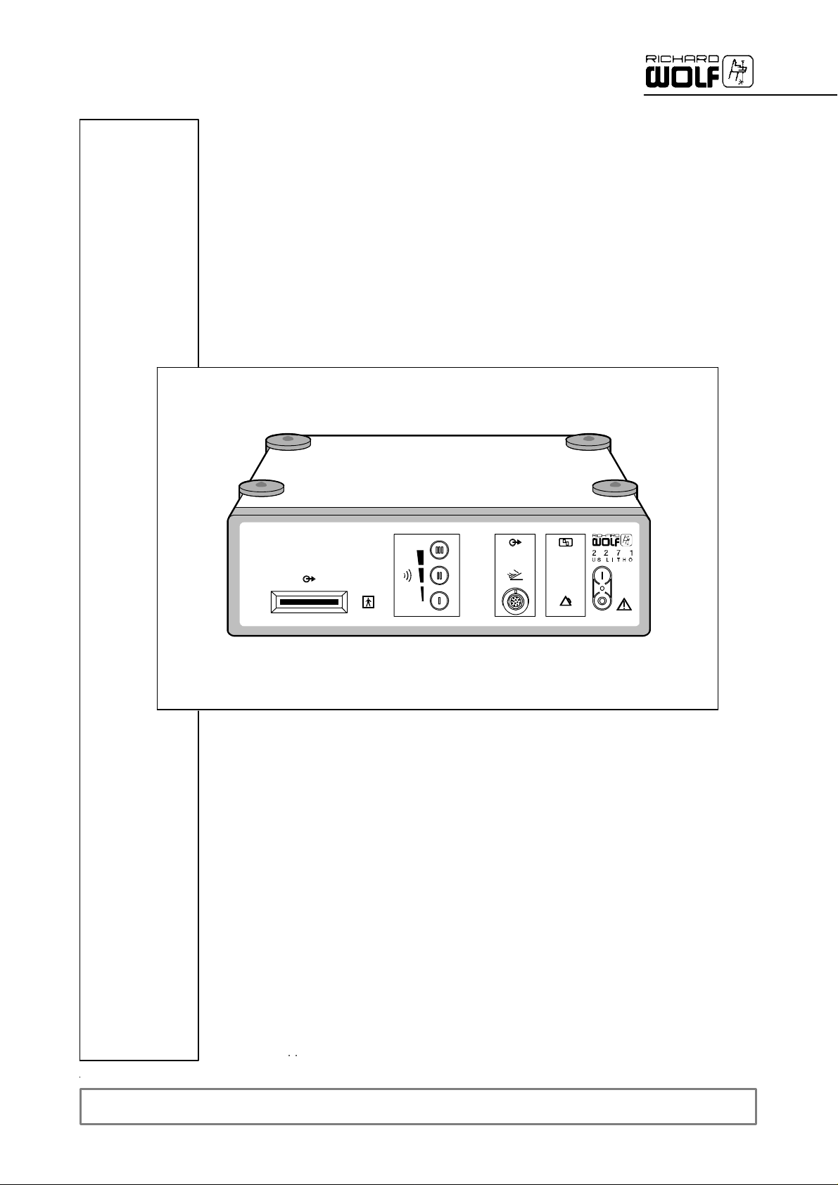
2Illustration
2.1 Front panel
1
3
4
2.1.1 Legend
1 Power switch with green LED 5 “Foot switch actuated” indicatorlamp
2 Socket for foot switch 6 “Transducermalfunction” warning lamp
3 Connection bar for transducer 7 “Generator malfunction”alarmlamp
4 Intensity buttonforpower stage preselection
5
2
6
7
6
GA--A 181
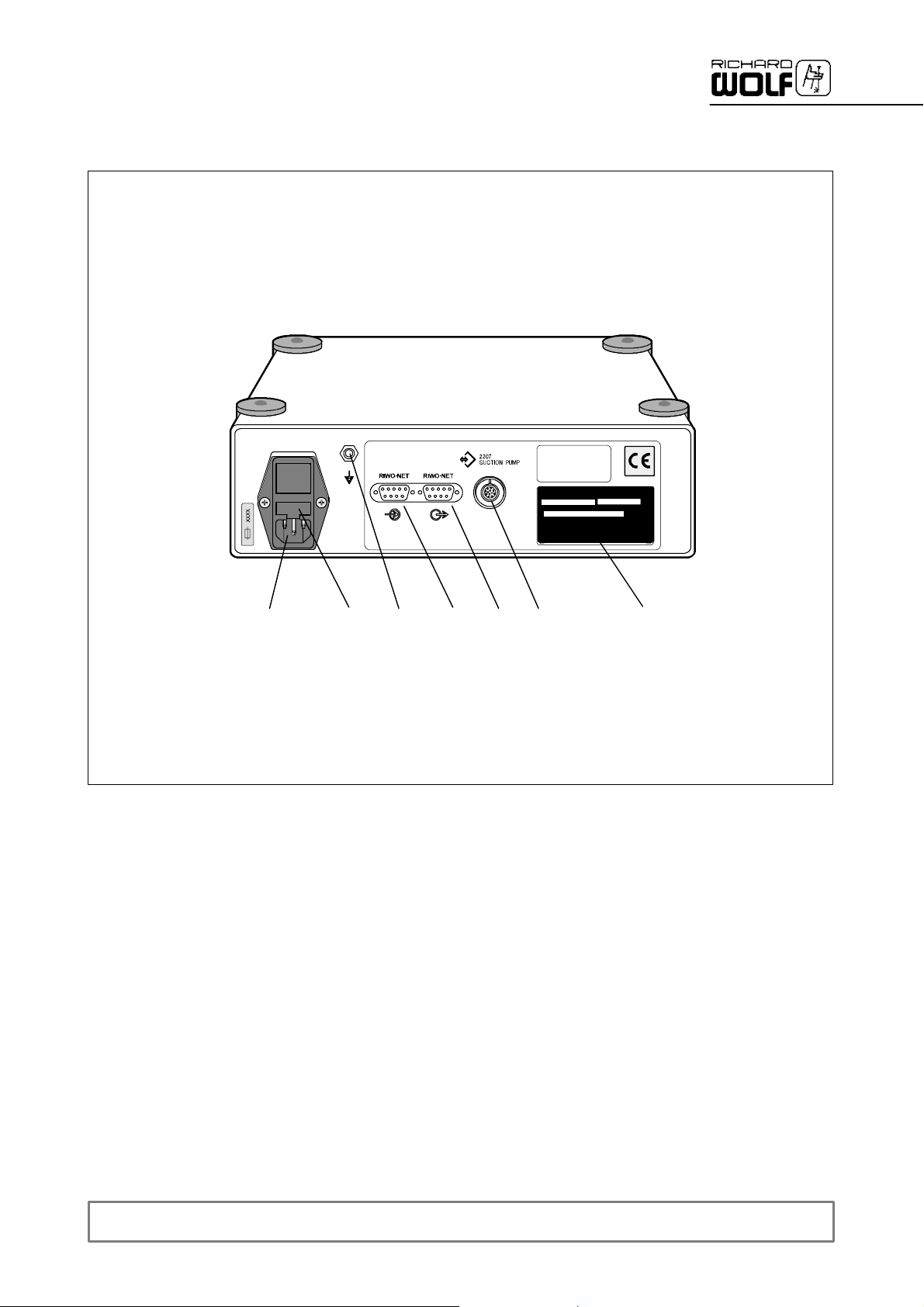
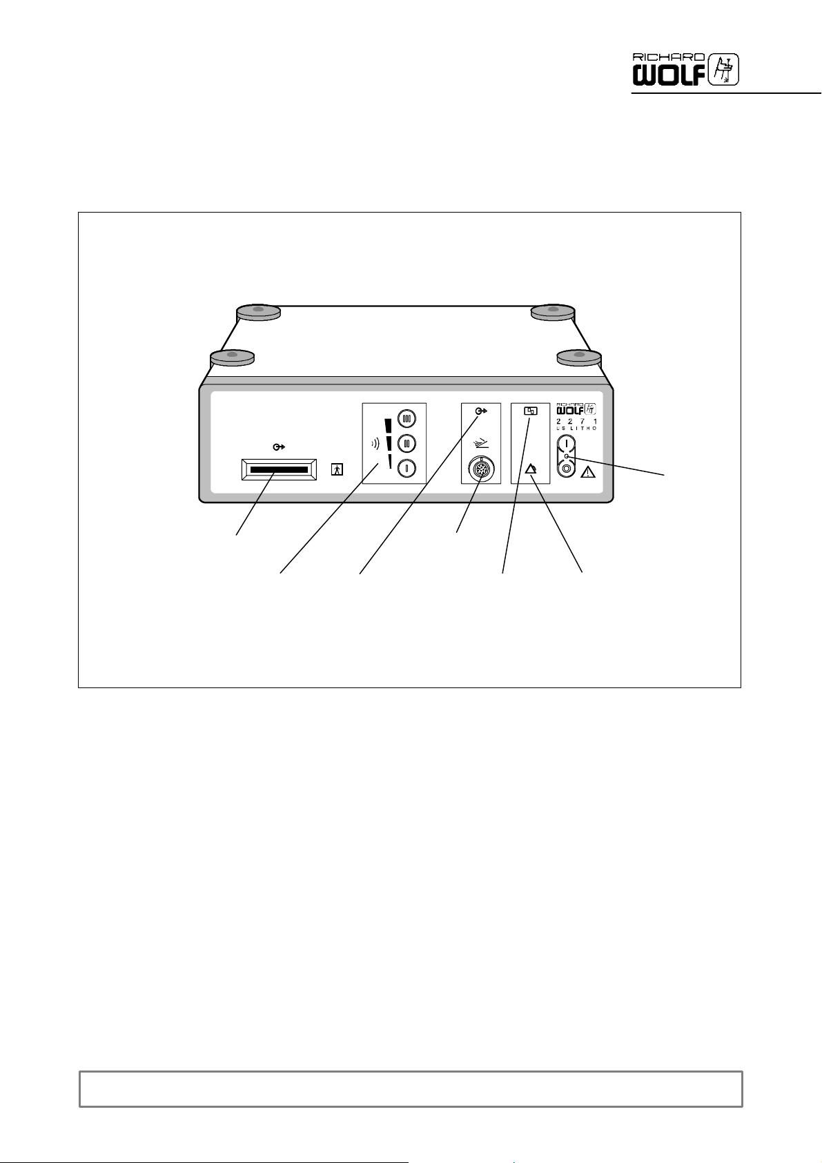
2.2 Rear panel
8
2.2.1 Legend
8 Power input connector with fuse holder 12.1 CAN --BUS inputconnector(option)
9 Fuse holder with device fuses 12.2 CAN --BUS outputconnector(option)
10 Control output for suction pump (4--pole socket) 13 Equipotentialconnector
11 Identification plate
9
12.1 12.2
10 1113
GA--A 181
7
3Setup
WARNING!
This device is not protected against explosions.
Explosion hazard.
Do not operate this device in areas where there is a danger of
explosions.
CAUTION!
Danger of faults and malfunctions.
To guarantee the safety of the user, the patient and others use only
accessories and spare parts specified by the manufacturer of this
product.
Other accessories or spare parts can cause the emission of
increased electromagnetic radiation or reduced immunity against
interference.
IMPORTANT!
.
Medical devices are subject to special precautions with regard to electromagnetic compatibility (EMC).
Make sure you observe the notes on EMC for installation and operation.
Medical electrical devices can be influenced by mobile HF communication devices.
If it is necessary to stack the devices or place them next to each other
and HF interference is observed, make sure you observe the intended
use of the devices.
CAUTION!
Danger of infection from unsterile accessories.
Sterilize reprocessed parts and accessory items before use.
Follow the sterilization instructions for the product in question!
IMPORTANT!
.
Make sure that the mains/grid voltage and the voltage indicated on the
identification plate are the same. Connect the device only through the
supplied power cord or a power cord meeting the same specifications.
NOTE!
.
During operation place the device on an even, level, non--slippery
surface.
8
GA--A 181

3.1 Preparation when using Suction Pump 2207
WARNING!
Danger of life threatening embolism due to wrong connection ofpump
tubes.
When using a peristaltic suction pump (e.g. Suction Pump 2207)no air or
liquid must be discharged from the sonotrode tip. The sonotrode tube only
serves for evacuation purposes. Strictly follow the instruction manual ofthe
suction pump used.
IMPORTANT!
.
The ultrasound generator is designed for use whilethe irrigation fluid is aspirated
and pumped off. When setting up the Ultrasound Generatormake sure that a suitable suction device is available.
The suction device should provide a continous adjustable vacuum of up to --0.6
bar.Werecommend using a suction device adaptedto the Ultrasound Generator
(e.g. Suction Pump 2207).
3.1.1 Ultrasound Generator with “Suction Pump 2207”
16
15
21
18
17
14
19
3.1.2 Legend
GA--A 181
14 Footswitch with cable 18 Suction connector
15 Transducer 19 Suction tube
16 Sonotrode 21 Suction connector of fluid trap
17 Transducercable with connection
bar
9

3.1.3 Rear panel connectors
8
11
20
Z The local mains/grid voltage and frequency must be the same as indi-
cated on “identification plate” (11).
Z Connect the supplied power cord to “power input connector” (8)ofthe
Ultrasound Generator and the other end to the wall socket.
3.1.4 Front panel connectors
19
18
15
16
Z Connect the control output of the Ultrasound Generator to the control
input of the Suction Pump using connection cable 2207.991 (20).
Connect the plugs to the corresponding sockets on the rear panels of
the devices and secure by turning clockwise.
Z Connect the plug of footswitch cable (14) to connection socket (2)of
the Ultrasound Generator.
Z Attach only approved sonotrode (16) to transducer (15). Ensure that
the contact surfaces are clean and the connection tight.
Z Plug the connector strip of transducer cable (17) into connection strip
(3) of the Ultrasound Generator.
Z Plug silicone suction tube (19) onto tube connector (18) of the trans-
ducer and connect the other end of suction tube (19) to the angle connector (i.e. suction connector) of fluid trap (21).
10
GA--A 181

4 Checks
.
4.1 Visual check
4.2 Functional checks
IMPORTANT!
Run through these checks before every use
Z Check devices, connectors and cables for correct setup and assembly
in accordance with the instruction manual(s).
Z Check all device connections and plug--and--socket connectors for
tightness, cleanliness and damage.
Z Check all connection cables and tubes for damage, hygenic condition
and completness.
Z Check devices, instruments and accessories for damage, hygenic con-
dition and completeness.
Z Check condition of the device sonotrodes in accordance with section
5.4.
Z Any lettering or labelling must be complete and easy to read.
.
CAUTION!
Danger of overheating of transducer and sonotrode.
Activate the transducer only if irrigation fluid is evacuated (pumped
off) through the transducer and sonotrode.
IMPORTANT!
.
Before you perform functional checks, make sure that the devices are in
perfect technical condition and are set up correctly, which is to be verified
in a visual check.
4.2.1 Ultrasound generator and transducer
Z Disconnect the connection bar of the transducer from the socket bar
on the device.
Z Switch on the Ultrasound Generator and preselect a power stage.
Z Actuate the foot switch briefly,
'to test transducer fault monitoring, the “transducer malfunction” (6)
warning lamp must light up.
Z Repeat this test for all power stages, then switch off the device.
GA--A 181
11

4.2.2 Ultrasound Generator and Suction Pump
Z Connect the transducer to the Ultrasound Generator.
Z Connect the suction tube of the pump to the transducer.
Z Place the sonotrode of a transducer in a suitable container (N) filled
with sterile liquid or irrigation fluid.
Z Switch on the Ultrasound Generator and Suction Pump.
'Pump function test: the “Transducer malfunction” warning lamp (6)
on the Suction Pump must not light up, the pump works at a low suction rate, i.e. speed.
Z Briefly actuate the foot switch.
'Pump control activation test: the suction rate/speed of the pump
must increase. If air or liquid is discharged from the sonotrode tip,
the pump tubes are incorrectly connected. Connect the tubes as
specified in the pump manual and follow the safety instructions. Repeat the test if required.
Z Preselect the highest power stage (4) on the Ultrasound Generator.
Z Actuate the foot switch.
'Transducer/sonotrode function test: the sonotrode must develop au-
dible vibrations and noises. For this purpose hold the sonotrode by
the transducer and remove it from the liquid just enough for the tip to
be still immersed to ensure reliable suction. Oscillation amplitudes
must be visible along the sonotrode tube.
'Suction test. The liquid level in liquid container (N) should have
dropped visibly. If the liquid level has not decreased sufficiently ,
N
check the sonotrode tube for clogging and clean it as described in
chapter 6 or replace it.
Z With the footswitch actuated, switch from the highest to the next lower
power stage.
'Generator malfunction monitoring test. During the switch--over the
“Generator malfunction” warning lamp (7) must light up briefly.
Z Repeat the switch--over test in all power stages including the lowest
power stage.
12
GA--A 181

5Use
5.1 Operating principle of Ultrasound Generator
The Ultrasound Generator generates an output voltage at a frequency
which corresponds to the resonance frequency of the oscillating system
consisting of the transducer and a suitable sonotrode. The Ultrasound
Generator 2271 automatically adapts to the resonance frequency ofthis
oscillating system.
Actuating the footswitch supplies an output voltage to the transducer output of the device.
The ultrasound energy is generated outside the body and outside the device, in the transducer. The output voltage of the Ultrasound Generator
excites two piezoceramic discs that transfer the ultrasound oscillations to
the sonotrode.
The excitation of the sonotrode causes a stationary wave at the resonance frequency which has its maximum amplitude at the distal end of
the sonotrode. Load--dependent changes in the oscillation behaviour are
compensated by a control circuit in the generator. Selecting the required
stage on the generator adapts the oscillation intensity to the requirements.
During operation, a safety circuit monitors the selected output power. If
the outputpower exceeds the selected value, the “Generator malfunction”
alarm lamp in the device lights up, at the same time an accustic alarm is
sounded and the transducer output is switched off.
5.2 Operating principle of ultrasound lithotripsy
Ultrasound lithotripsy systems are used for minimally invasive desintegration of urinary bladder stones, kidney stones and ureter stones. Access to
the stone is gained endoscopically via the urethra or percutaneously directly into the kidney. The stone is desintegrated under endoscopic view
by contact with the sonotrode.
The stone fragments are pumped off through the sonotrode together with
the irrigation fluid. Suction is achieved by a vacuum generated by a
preadjustable suction pump via a fluid trap. The stone fragments and debris are collected in the fluid trap while the irrigation fluid is pumped via
an overflow device into the drain.
GA--A 181
13

5.3 Operation of Ultrasound Generator
CAUTION!
Danger of overload and fracture of the sonotrode.
Using the sonotrode at a higher power setting than the maximum
permissible power stage can lead to premature material fatigue and
fracture of the sonotrode.
It is not permissible using the sonotrodes at higher power stages
than the maximum permissible power stage indicated.
CAUTION!
Danger from overheating of transducer and sonotrode.
During operation, cool the transducer and sonotrode by continous
suction. Operating the device without or with insufficient suction
and cooling can lead to overheating and damage due to quick and
severe wear.
Never operate the device without adequate suction or cooling.
CAUTION!
Danger of burns! Mind your fingers!
Do not hold the activated sonotrode between your fingers.
IMPORTANT!
.
The tip of the sonotrode must be visible at all times.
The sonotrode tip must be in contact with the stone while activated.
Avoid contact of tissue with the tip or sides of the sonotrode ; tissue damage could result.
Avoid pressing the probe against the endoscope during operation. This
may stall the transducer and heat the sonotrode with in the working channel.
IMPORTANT!
.
Do not drop or struck the transducer against another object with may result in mechanical or electrical damage.
IMPORTANT!
.
During operation make sure that the transducer and the sonotrode are
sufficiently cooled by fluid suction.
We recommend having a transducer and the required sonotrodes available as backup units.
NOTE!
.
When using the device we recommend wearing the supplied ear protection.
14
GA--A 181

5.3.1 Controls and indicators of Ultrasound Generator 2271 (US--LITHO)
The Ultrasound Generator is switched on and off by means of mains/
5
4
14
5.3.2 Ultrasound Generator ON/OFF
6
1
7
power switch (1) with green LED.
To preselect the required power stage, actuate the corresponding inten-
sity button (4).
Actuating the foot switch (14) triggers two functions:
-- The transducer is activated.
-- The suction rate increases to the preselected value.
When the footswitch is depressed, the “ footswitch actuated” indicator
lamp (5) lights up.
Malfunctions of the transducer are indicated by the “transducer malfunction” warning lamp (6).
Malfunctions ofthe generator are indicated by the “generator malfunction”
alarm lamp (7).
Z To switch the Ultrasound Generator on/off, use mains/power switch (1).
' The green LED (1) on the power switch and the background illumina-
tion of the warning/signal lamps as well as the intensity buttons light
up.
IMPORTANT!
.
If the LED and the background illumination remain dark after switching on
or if the “transducer malfunction” warning lamp (6) or the ”generator malfunction” alarm lamp (7) light up, follow the troubleshooting list under
section 7.1.
GA--A 181
15

5.3.3 “Intensity” preselection (power stage)
CAUTION!
Danger of overload and fracture of the sonotrode.
Using the sonotrode at a higher power setting than the maximum
permissable power stage can lead to premature material fatigue and
fracture of the sonotrode.
It is not permissable using the sonotrodes at higher powers stages
than the maximum permissable power stage indicated.
IMPORTANT!
.
Depending on the sonotrode diameter the following power stages are
permissable:
Sonotrode ∅ maximum power stage
1.5 -- 2.4 mm II
3.5 -- 4.0 mm III
Z After switching on the device, power stage I is set.
' Use the lowest power stage in which the stone can be effectively dis-
integrated.
Z Preselect the required power stage by actuating the corresponding in-
tensity button (I = low power,III = high power).
' The power stage selected is indicated by the intensity button lighting
up.
5.3.4 Activation of transducer
Z Activate transducer by actuating the footswitch.
' Via the “Suction Pump control output” (10) the suction rate (power) of
the suction pump increases to the preselected value by send in/out a
signal.
' The “Foot switchactuated” indicator lamp (5) lights up.
NOTE!
.
If the transducer is activated for some time and if the temperature of the
grip becomes excessively high we recommend changing the transducer.
5.3.5 ”Transducer malfunction” warning lamp
Z Lights up in case of a transducer malfunction.
5.3.6 ”Generator malfunction” alarm lamp
Z Lights up if the preselected output power/rate is exceeded or if the Ul-
trasound Generator is defective.
' The device switches off, accompaniedby an accustic alarm.
16
GA--A 181

5.4 Changing the sonotrode
CAUTION!
Danger if a damaged or non-approved sonotrode is used.
Using the device with damaged sonotrodes or sonotrodes which are
not approved for this device is not permissible.
Replace sonotrodes immediately, use only sonotrode models approved for this device by R.Wolf and which are sterilized and in perfect technical condition.
IMPORTANT!
.
Bent or damaged sonotrodes may damage the instruments.
Before use make sure that only sonotrodes in perfect technical condition
and of the type and model approved for this device and this transducer
are used.
When attaching the sonotrode ensure firm connection.
5.4.1 Checking the sonotrodes
IMPORTANT!
.
After each use clean the sonotrode and transducer flange surfaces with a
brush, as residues on these surfaces will cause malfunctions.
GA--A 181
22
23
24
Z Check the sonotrode for cleanliness and wear.
' The sonotrode mustbe clean and free of residues inside (sonotrode
channel) and out.
' The sonotrode mustneither be scratched nor cracked or bent, as this
may cause a fracture of the sonotrode.
The tip (22) must not be flared towards theinside or have sharp
edges, and must not be worn in any way.
Z Check the connector (23) for firm connection, the flange surface and
threaded portion (24) of the adapter portion for cleanliness and damage.
' The adapter mustbe firmly connected to the sonotrode tube.
' The thread and flange surface must not have any residues on them
nor be damaged in any way.
Replace sonotrodes which are worn, bent or damaged.
The sonotrodes approved by R.Wolf for use with this device are listed in
section 7.4.
17

5.4.2 Changing the sonotrodes
The sonotrodes are connected to the transducer through the fine thread
on the adapter flange. To ensure a reliable transmission of the sound energy generated in the transducer to the sonotrode, neither the thread nor
the flange surfaces of the sonotrode or transducer musthave any residues or damage on them, and the threaded connection must be sufficiently tight.
Disassembly:
Z Use the supplied quarter inch open--ended wrench on the sqare of the
adapter andloosen the sonotrode by turning counter clockwise (CCW).
Then unscrew the sonotrode by hand.
Assembly:
Z Screw the new sonotrode into the transducer thread by hand, by turn-
ing clockwise (CW) as far as it will go. Then apply the quarter inch
open--ended wrench to the square of theadapter flange and carefully
tighten the connection by approx. 15_.
' The connection must be tight but the thread should not be tightened
with excessive force.
NOTE!
.
If the sonotrode makes a rattling noise or if the sonotrode has insufficient
drilling power, check that the screw connections are tight and the flange
surfaces of the sonotrode and the transducer are clean.
18
GA--A 181

6 Operation in the RIWO NET SYSTEM
6.1 Combination with RIWO NET SYSTEM
Via the integrated CAN--BUS interface the ultrasound generator 2271can
be integrated into the R.Wolf RIWO NET SYSTEM.
Only the components approved for use with the RIWO--NET--SYSTEM
must be connected to the “CAN--BUS” interface.
The components must meet the requirements of the latestinstruction
manual for the RIWO--NET--SYSTEM, section on “Combinations”.
The control computer complies with IEC / EN 60601--1 and can be operated in the patient environment.
IMPORTANT!
.
In addition to this manual make sure you follow the latest manual for the
RIWO--NET--SYSTEM.
6.2 Operation
The instruction set used in the interface software is suitable for operating
this device within the RIWO NET SYSTEM.
The ultrasound generator unit can be controlled via the RIWO NET SYSTEM with remote control, speech control, touch--screen monitor or manually via the buttons on the device front panel.
IMPORTANT!
.
The ultrasoundgenerator unit can still be operated via the front panel buttons, should the RIWO NET SYSTEM fail.
IMPORTANT!
.
To fully understand the system please read the latest manual for the
RIWO--NET--SYSTEM.
IMPORTANT!
.
For control via the touch-- screen monitor it is sufficient to touch the monitor surface only slightly.
GA--A 181
19

6.3 Connection to the RIWO NET SYSTEM
Touch--Screen
Monitor
z.B.
Video printer
z.B.
Video recorder
RS--232
RS--232
Control computer
RIWO CONTROL
CAN--BUS
e.g.
Ultrasound
generator
CAN--BUS
e.g.
Light projector
CAN--BUS
e.g.
Camera
Connection of headset microphone
CAN--BUS termination
IMPORTANT!
.
The device system must be operated via a “Separating transformer with DC coupling”.
IMPORTANT!
.
The last device in the CAN--BUS chain requires a termination using thesupplied terminating resistor.
20
GA--A 181

6.4 Controlling the devices using the RIWO--NET menu
6.4.1 Controlling the devices via the different input media
Via Touch--Screen Monitor:
-- The function is selected and executed by gently touching the desired
menu function (button) directly on the Touch--Screen Monitor.
Via voice control:
-- The same instructions/commands must be used as displayed on the
Touch--Screen Monitor.
-- If an instruction/command consists of a “Function” and an “Action”,
both terms must be pronounced one after the other without pausing.
Example: “SUCTION RATE” -- “MINUS” or “SUCTION RATE” -- “PLUS”
-- Before and after each instruction/command, a short pause of
approx. 0.5 seconds is required.
Via remote control unit:
-- The arrow buttons serve to select the corresponding device in the main
menu and the corresponding function in the submenu.
-- The yellow buttons serve to execute the corresponding action.
-- The blue buttons serves to return tothe main menu.
From the main menu, the RIWO NET SYSTEM can be exited,
in which case the computer is shut down automatically.
6.4.2 Illustration of menu
1
3
Legend
1 Control menu 3 System messages
2 Status display 4 Back to main menu
2
4
GA--A 181
21

6.4.3 Main menu
The main menu lists all devices connected to the RIWO NET SYSTEM.
Selecting a device calls up and displays the corresponding device menu.
6.4.4 Ultrasound output function
Z The “Ultrasound output” menu item serves to preselect the output
power stage 1, 2 or 3 of the ultrasoundtransducer.
6.5 System messages
IMPORTANT!
.
If you cannot eliminate the fault or error with the help of this table, please
contact theservice department or return the device for repair.
' Do not attempt to do any repairs yourself!
L Depending on the status or error state the POWER CONTROL displays
the following messages on the RIWO--NET menu monitor:
6.5.1 Operating instructions
Message type Message text Possible cause Remedy
Operating
instruction 1
“+ Voice output” = In the case of the system messages marked with this symbol an additional acoustic warning is sounded
Maximum output selected
(only if the “ Voice output” option is available).
Stage 3 is s elected, although this
stage has already beenselected.
' -- -- ----
6.5.2 Warnings
Message type Message text Possible cause Remedy
Warning 1 Malfunction of transducer or sonotrode
Sonotrode is not in resonnance
because the sonotrode is not firmly
bolted down, the flange surfaces of
the sonotrode or transducer are
soiled or the wrong powersetting
has been preselected.
'Firmly bolt down the sonotrode
'Clean the flange surfaces of the
sonotrode or transducer
'Select a different power stage.
6.5.3 Error messages
Message type Message text Possible cause Remedy
When actuating the footswitch, for
Fault 1 Ultrasound output power too high
1 second the current ultrasound
output power is higher than the
preselected power.
'Contact the service dpt.
22
GA--A 181

7 Reprocessing and maintenance
7.1 Reprocessing of device
WARNING!
Danger if moisture enters in the device.
Danger of electric shock.
Before reprocessing, the device must be switched off and disconnected from the mains/power supply.
The device can be cleaned with a soft cloth soaked with surface disinfectant, alcohol or spirit.
Follow the disinfectant manufacturer’s instructions.
IMPORTANT!
.
Make sure that no humidity enters in the device. Do not use any cleaning
agents, scouring agents or solvents on the device!
GA--A 181
23

7.2 Reprocessing of accessories
CAUTION!
Danger of infection due to unsterile parts and accessories.
Sterilize reprocessible parts and accessories before use. Follow the
regulations on sterilization valid in your country.
IMPORTANT!
.
Follow the procedures described in the “General instructions and
notes on the reprocessing of R. Wolf products, accessories and
devices” (order no.: GA--J 020) .
7.2.1 Wet preparation at the point of use
After use immerse used accessory items such as transducer, sonotrodes
and suction tube in a disinfectant solution for wet preparation at the point
of use.
For this pupose follow the disinfectant manufacturer’s instructions!
Z Disconnect connection bar (17) of the transducer (15) from the device.
Disconnect suction tube (19) from the tube connector on the device.
Immerse accessories in the solution for wet preparation at the point of
use.
7.2.2 Disassembly before cleaning
16
15
18
17
19
Remove accessories items before cleaning.
Z Unscrew the sonotrode (16) with the supplied open--ended wrench
(size: quarter inch) by turning counter clockwise (right hand thread).
Disconnect suction tube (19) from tube connector (18) of the trans-
ducer.
24
GA--A 181

7.2.3 Manual cleaning
25
Prior to disinfection, clean and dry disassembled accessory items manually as follows:
Z Transducer:
Clean transducer (15) and rinse transducer channel with a cleaning
gun.
Clean the transducer with a suitable cleaning rod (2167.508) first from
the distal end, then from the proximal end (tube connector). Ensure
that the transducer channel is clean and free of residues through its
entire length.
Clean the flange surface of the transducer with a brush.
Clean the transducer channel with a cleaning gun, and dry the channel
with compressed air , the transducer surface with a cloth.
A
16
B
7.2.4 Machine cleaning
Z Sonotrodes:
Clean sonotrodes (16) and rinse sonotrode channel with a cleaning
gun.
Clean sonotrodes with a suitable cleaning rod (25) first distally (A),
then proximally (B adapter flange) from both ends. Ensure that the sonotrode channel is clean and free of residues over its entire length.
Clean the flange surface of the sonotrode with a brush.
Clean the sonotrode channel with a cleaning gun, and dry the channel
with compressed air , and the sonotrode surface with a cloth.
Check the sonotrodes for wear and damage as described in section
5.4.1, dispose of damaged or worn sonotrodes as required by the regulations.
Z Suction tube:
Clean the suction tube (19) and rinse with a cleaning gun from both
ends. Make sure that the tube is free of residues inside and out
throughout its entire length.
Then dry the tube channel with compressed air and the outside with a
cloth.
Z Sonotrodes:
Due to the length and the small internal dimensions of the sonotrode,machine cleaning is not recommended.
GA--A 181
Z Transducer:
The transducer can be reprocessed manually. To prevent any damage
to the transducer, we recommend using the transducer reprocessing
basket (3801 1.501). See instruction manual GA--J 040.
25

7.2.5 Disinfection
7.2.6 Steam sterilization
7.2.7 Assembly
For disinfection, immerse accessories in disinfectant solution. Before you
immerse the parts fill the channels of the transducer, sonotrode and suction tube completly with disinfectant using a syringe.
Follow the disinfectant manufacturer’s instructions!
After disinfection dry the channels of the accessory items with compressed air and the surfaces with a sterile cloth.
NOTE!
.
Do not use disinfectants containing chlorine or phenole derivate for the
disinfection of R. Wolf products.
Avoid immersion/soaking times of more than two hours!
Never steam--sterilize the tranducer and the sonotrodes in assembled
condition!
To sterilize the transducer, we recommend the transducer reprocessingbasket (3801 1.501). See instruction manual GA--J 040.
Z Steam sterilization at 134°C (272°F) using the fractional method.
Assemble accessories only immediately before use and in reverse order
as described under ’Disassembly’.
Follow assembly instructions for sonotrodes under section 5.
Perform the neccessary checks before each use in accordance with
section 4.
7.2.8 Reprocessing of foot switch
The device can be cleaned with a soft cloth moistened with surface disinfectant, alcohol or spirit.
Follow the disinfectant manufacturer’s instructions!
26
GA--A 181

7.3 Maintenance of device and accessories
7.4 Maintenance
NOTE!
.
In your correspondence please always specify the model/type and series
number indicated on the identification plate. If required further documentation is available from the manufacturer.
7.4.1 Maintenance intervals
IMPORTANT!
.
To prevent damage that results from ageing and wear of the device and
the accessories maintenance must be carried out at adequate intervals.
Depending on the frequency of use, however every twelve months at the
latest, have an expert check the functional and operational safety.
7.5 Quarterly check
IMPORTANT!
.
The check may only be performed by qualified and adequately trained
personnel of the user.
Do not use the devices if the specified values are not displayed or the
functions are not fulfilled.
If the specified values and tolerances are not adhered to, the system
must be checked by an authorized service technician.
NOTE!
.
The quarterly check must comprise a visual check as described in section 4.1.
7.5.1 Measuring devices and auxiliary means for checking
Z Transducer with sonotrode and suction tube.
Suction device or suction pump with accessories.
Transparent container (e.g. measuring vessel with a contents of
approx. 2--4 litres)
IMPORTANT!
.
When testing the function of the Ultrasound Generator, make sure that
liquid is pumped off through the sonotrode.
GA--A 181
27

7.5.2 Visual check
7.5.3 Functional checks
Z Check the device setup, connection and connection cable for correct-
ness in accordance with section 3 of this manual.
CAUTION!
Danger of transducer or sonotrode overheating.
Thetransducer must only be activated if irrigation fluid is pumped off
through the sonotrode at the same time.
IMPORTANT!
.
Before you carry out a function check, make sure that the devices and
accessories are in perfect technical state and have been set up correctly.
To ensure this, carry out a visual check.
Function test of Ultrasound Generator and transducer:
Z Connect the transducer to the Ultrasound Generator and the suction
tube to the suction connector of the transducer.
Z Place the transducer together with the sonotrode in a suitable con-
tainer filled with sterile liquid or irrigation fluid.
Z Switch on the Ultrasound Generator and the suction function, and ad-
just the suction rate.
Z Select the highest power stage on the Ultrasound Generator, hold the
transducer and briefly actuate the footswitch.
'The sonotrode should start vibrating and generate noise. For this
purpose lift the transducer with the sonotrode out of the liquid to the
extent that the tip remains immersed far enough to ensure reliable
suction. Oscillation amplitudes must be visible along the sonotrode
tube.
If the noise is only low or if the sonotrode clanks audibly, check the
screw connection of the sonotrode. When assembling the sonotrode
and the transducer, make sure that the flange surfaces are clean
and the screw connection is tight. Then repeat the test.
If neither oscillations nor a noise is generated or the “transducer malfunction” (6) warning lamp lights up, repeat the test with a spare
transducer.
28
Test generator fault monitoring:
Z With the footswitch actuated, switch from the highest to the next lower
power stage.
' During switch--over, the “ generator malfunction” alarm lamp (7)
should light up briefly.
Z Repeat switch--over test until the lowest stage is reached.
GA--A 181

NOTE!
.
The drilling performance of the sonotrode can be tested with the help of a
test item (surgically removed kidney stone or comparable material). For
the test, use the same setup and procedure as described under “transducer/sonotrode function check” as well as the following test routine:
Z Prepare the Ultrasound Generator and Suction Pump as for the func-
Z Place the test item in a container filled with irrigation fluid.
Z Hold the transducer in such a way that the sonotrode tip touches the
Z Actuate the foot switch.
7.6 Tech n ical safety ch eck
IMPORTANT!
.
Technical safety checks may only be carried out by the manufacturer or
persons with special technical knowledge.
The test results must be documented and included in the device accompanying book.
Do not use the device if the specified values are not shown or measured,
or functions are not fulfilled.
tion tests of the transducer and sonotrode.
test item (do not press, use suction effect of pump).
'Within a matter of a few seconds the sonotrode should drill into the
stone. The drilling effect will depend on the sonotrode contact as well
as the hardness of the test item. Switch to the different power stages
to check the drilling behaviour at different intensity settings.
Test interval:
Every 12 months, perform a technical safety check with the following
scope:
Z Visual check for completness, contamination, aging and wear.
'Check lettering and labelling for proper condition and legibility.
'Check electrical lines and connectors for condition, possible damage
and correct connection.
'Check liquid delivery systems for leakage.
Z Electrical safety check to IEC/EN 60601--1.
'Check protective ground/earth connection.
'Check leakage current.
Z Check function in accordance with this manual.
GA--A 181
29

8 Technical description
8.1 Trouble shooting
IMPORTANT!
.
If you cannot eliminate the faults with the help of this table, please contact the service department or return the device for repair.
' Do not attempt to do any repairs yourself!
8.1.1 Device faults
Fault/error Possible cause Remedy
Device without function -- Mains/powerswitch not on
-- Power cord not connected
-- Device fuse defective
-- No mains/line voltage
“Generatorfault” alarm lamp (7)lights
up when the device is switched on
Transducerwithoutfunction -- Foot switch incorrectly connected
“Transducermalfunction” warning
lamp (6)lights up when the footswitch
is actuated
No sonotrode oscillation/ improper
oscillation
-- Device defective 'Contact service department or return
-- Transducerimproperly connected
-- Presetpower stage button is not lit
-- “Footswitch actuated” signal lamp
(5) does not light upwhen actuating
the footswitch
-- Transducerdefective
-- Sonotrodeimproperly connected
-- Sonotrodeimproperly connected
'Actuate mains/power switch
'Connect power cord
'Replace fuse
'Check in--house power supply
the device for repair
'Connect foot switch/ check plug for
correctconnection
'Connect transducer/ check plug for
correctconnection
'Contact service department or return
device for repair
'Contact service department or return
device for repair.
'Replace transducer
'Check screw connection ofsono-
trode for correct and tight connection.
'Check screw connection ofsono-
trode for correct and tight connection.
30
-- Sonotrodedamaged
-- Transducerdefective
-- Flange surface of sonotrode or
transducersoiled
-- Device defective
'Check sonotrode for proper operation or replace
'Replace transducer
'Clean flange surfaces
'Contact service department or return
device for repair
GA--A 181

8.2 Tech n ical d ata
8.2.1 Electrical connection
Voltage
Model/type
µ
V
2271.001 230 50 / 60 200 0.9 T1.25L
2271.002 100 50 / 60 200 2.0 T2.50L
2271.003 110 / 115 50 /60 200 1.8 T2.50L
2271.004 120 / 127 50 / 60 200 1.7 T2.50L
2271.101 230 50 / 60 200 0.9 T1.25L
2271.102 100 50 / 60 200 2.0 T2.50L
2271.103 110 / 115 50 /60 200 1.8 T2.50L
2271.104 120 / 127 50 / 60 200 1.7 T2.50L
Frequency
Hz
Power
consumption
VA
Current
rating
A
8.2.2 Technical data of ultrasound generator
Electromagnetic compatibility (EMC) to IEC / EN 60601--1 --2
Medical Devices Directive 93/42/EEC Class II b
Protection againstelectric shock see transducer
Protection class to IEC / EN 60601--1;
(UL 2601--1 /CSA C22.2 No.601.1 -- for USA)
I
Fuse
A
Degree of protection against the ingression of liquid IP 20 (Not protected)
Duty factor
Noise level 75 dB(A)
Degree of protection in the presence offlammable gasses
Weight 8.5 kg(18.7lbs)
Dimensions WxHxD 320 mm x 105 mm x 360 mm
(Do not operate this device in flammable environments)
Continous operation with load interval
(INT.20sec/20sec)
This device is notprotected against explosions
8.2.3 Interfaces of ultrasound generator
Transduceroutput 1 x connector strip, 2 x 9--pole
Footswitch output connector 1 x socket, 3--pole
Suction device output socket (Suction Pump) 1 x socket, 4--pole
Connectors for RIWO NET SYSTEM (option) 2 x socket, 9--pole
GA--A 181
31

8.2.4 Technical data of transducer (2271.501)
Protection againstelectric shock BF type applied part
Degree of protection against the ingression of liquids IP 67
Degree of protection in the presence offlammable
gasses
Weight 0.300 kg (0.7 lbs)
Dimensions (dia. x length) 30 mm x 143 mm
This device is notprotected against explosions.
(Do not operate this device in flammable environments)
8.2.5 Technical data of footswitch (2030.12)
Degree of protection against the ingression of liquid: IP 68
Degree of protection in the presence offlammable
gasses
Weight 0.730 kg (1.61 lbs)
Dimensions (Widthx height x length) 70 mm x 61 mm x 220 mm
This device is notprotected against explosions.
(Do not operate this device in flammable environments)
8.3 Operating, storage, transport and shipping conditions
ambient temperature + 10°Cto+40°C,
Operatingconditions
atmosphericpressure 700 hPa to 1060 hPa
Storage, transportand shipping conditions
atmosphericpressure 700 hPa to 1060 hPa
30% to 75% rel. humidity,
ambient temperature -- 20°Cto+60°C,
10% to 90% rel. humidity,
NOTE!
.
To avoid damage to the products during transport or shipment we recommend using the original packaging material.
32
GA--A 181

8.4 Spare parts and accessories
Ultrasound generator
Units Model/type Designation
1 64268.003 Device fuse T 1.25 L (pack of 10St.)
1 72315.008 Device fuse T 2.5 L (pack of 10)
1 2440.03 Power courd (Europe), 3.0 m
1 64221.093 Suction tube, dia. 5.0mm , length 2.0 m, 60 shore
1 2167.951 Ear plugs (Ear protection, pack of 10)
1 2030.12 Foot switch
1 2271.501 Transducer
1 74003.009 Open end wrench (size1/4inch)
In addition for 2271.10x:
1 103.701 CAN BUS connection cable, length 0.6 m
Probes for Nephroscopy
Units Model/type Designation
1 8962.519 Sonotrode (dia.1.9 mm, working length 361 mm, straight)
1 8962.524 Sonotrode (dia.2.4 mm, working length 359 mm, straight)
1 8963.535 Sonotrode (dia.3.5 mm, working length 358 mm, straight)
1 8962.541 Sonotrode (dia.4.0 mm, working length 358 mm, straight)
1 8963.635 Sonotrode with core drill bit (dia. 3.5 mm, working length 370 mm, straight)
1 8962.641 Sonotrode with core drill bit (dia. 4.0 mm, working length 360 mm, straight)
Probes Uretero--renoscopy
Units Model/type Designation
1 8954.515 Sonotrode (dia. 1.5 mm, working length 564mm, straight)
1 8954.519 Sonotrode (dia.1.9 mm, working length 562 mm, straight)
1 8959.515 Sonotrode (dia.1.5 mm, working length 444 mm, straight)
1 8959.519 Sonotrode (dia.1.9 mm, working length 458 mm, straight)
Others
Units Model/type Designation
1 2167.508 Cleaning rod for transducer and sonotrodes, dia.3.5 -- 4.0 mm
1 2167.509 Cleaning rod for sonotrodes, dia. 1.5 -- 2.4 mm
1 38011.501 Reprocessing basket for transducer
1 2207.991 Device connection cable (4 pole)
' further accessories on request
GA--A 181
33

8.5 Replacing parts
8.5.1 Device fuses
CAUTION!
The specification of the fuses in the device must correspond with
the fuse ratings on the identification plate.
Use only the fuses specified in the spare parts list.
L Device power connector with fuse holder
1
2
Z Switch off the device and disconnect the power cable from both the
wall socket and the device connector.
Z Use a screwdriver to remove the fuse holder (1).
Z Then remove the fuses (2) from the fuse holder (1) and replace.
Z Reinsert the fuse holder and push until it snaps into place.
8.5.2 Disposal of the product, packing material and accessories
For the disposal make sure you adhere to the regulations and laws valid
in your country.
' For further information please contact the manufacturer.
2
34
GA--A 181

9 Literature
IMPORTANT!
.
As we cannot provide a comprehensive bibliography we would ask users
to keep themselves informed of all new developments in this field.
Z Atlas der urologischen Endoskopie
Band 2: Diagnostik und operative Endoskopie
Hans Joachim Reuter
1984, Georg Thieme Verlag Stuttgart, New York
Z Extra-- und Intrakorporale Lithotripsie
Ch. Ell,M. Marberger, P.Berlien
1990, Georg Thieme Verlag Stuttgart, New York
GA--A 181
35
 Loading...