

Page 1
Wolf GmbH · Postfach 1380 · 84048 Mainburg · Tel. 08751/74-0 · Fax 08751/741600 · Internet: www.wolf-heiztechnik.de
Art.-Nr. 30 44 829 Änderungen vorbehalten! 05/06
Wartungsanleitung
Gasbrennwertgeräte
GB-11, TGB-11
GB-20, TGB-20, GB-20-S
Seite 2
D
Service Manual
Gas condensing boilers
GB-11, TGB-11
GB-20, TGB-20, GB-20-S
Page 21
GB
Istruzioni per la manutenzione
Caldaie murali a condensazione
GB-11, TGB-11
GB-20, TGB-20, GB-20-S
pagina 41
I
Page 2

2
Inhaltsverzeichnis Seite
Sicherheitshinweise...............................................................................................................................................3
Wartungsablauf .............................................................................................................................................. 4-18
Liste benötigter Teile ........................................................................................................................................... 19
Übersicht der Arbeitsschritte mit Wartungsprotokoll .............................................................................. 20
Wartungsanleitung
Page 3
3
In dieser Beschreibung werden die folgenden Symbole
und Hinweiszeichen verwendet. Diese wichtigen Anweisungen betreffen den Personenschutz und die
technische Betriebssicherheit.
"Sicherheitshinweis" kennzeichnet Anweisungen, die genau einzuhalten sind, um Gefährdung oder Verletzung von Personen zu vermeiden und Beschädigungen am Gerät zu
verhindern.
Gefahr durch elektrische Spannung an elektrischen Bauteilen!
Achtung: Vor Abnahme der Verkleidung
Betriebsschalter ausschalten.
Greifen Sie niemals bei eingeschaltetem Betriebsschalter an elektrische Bauteile und Kontakte!
Es besteht die Gefahr eines Stromschlages mit
Gesundheitsgefährdung oder Todesfolge.
An Anschlußklemmen liegt auch bei ausgeschalteten Betriebsschalter Spannung an.
"Hinweis" kennzeichnet technische Anweisungen, die zu beachten sind, um Schäden und
Funktionsstörungen am Gerät zu verhindern.
Achtung
Bild: Gasanschluß: Gefahr von Vergiftung und Explosionsgefahr durch auströmendes Gas
Bild: Klemmkasten:
Gefahr durch elektrische Spannung
Bild: Zündtrafo, Hochspannungs-Zündelektrode,
Brennkammer
Gefahr durch elektrische Spannung, Gefahr von Verbrennung durch heiße Bauteile
Bild: Gaskombiventil
Gefahr durch elektrische Spannung
Gefahr von Vergiftung und Explosion durch auströmendes
Gas
Wartungsanleitung
Allgemeine Hinweise
Alle Wartungsarbeiten dürfen nur von einem Fachhandwerker durchgeführt werden.
Regelmäßige Wartung sowie die ausschließliche
Verwendung von Original Wolf-Ersatzteilen sind
für einen störungsfreien Betrieb und lange Lebensdauer Ihres Gerätes von entscheidender Bedeutung.
Wir empfehlen daher einen Wartungsvertrag mit
Ihrer Fachhandwerkerfirma abzuschließen.
Sicherheitshinweise
Page 4
4
Wartungsanleitung
•Therme am Betriebsschalter ausschalten.
An den Netzanschlußklemmen des Gerätes liegt
auch bei ausgeschaltetem Betriebsschalter elektrische Spannung an.
•Anlage spannungsfrei machen.
Gashahn schließen.
•Heizung absperren.
Page 5
5
Wartungsanleitung
• Kaltwasser absperren.
•Brennraumgehäuse öffnen.
Verbrennungsgefahr
Verschiedene Bauteile können sehr heiß sein. Abkühlen
lassen oder Handschuhe anziehen.
•Alle Kabel am Brennkammerdeckel abziehen.
•Stecker am Gasgebläse lösen.
Page 6
6
Wartungsanleitung
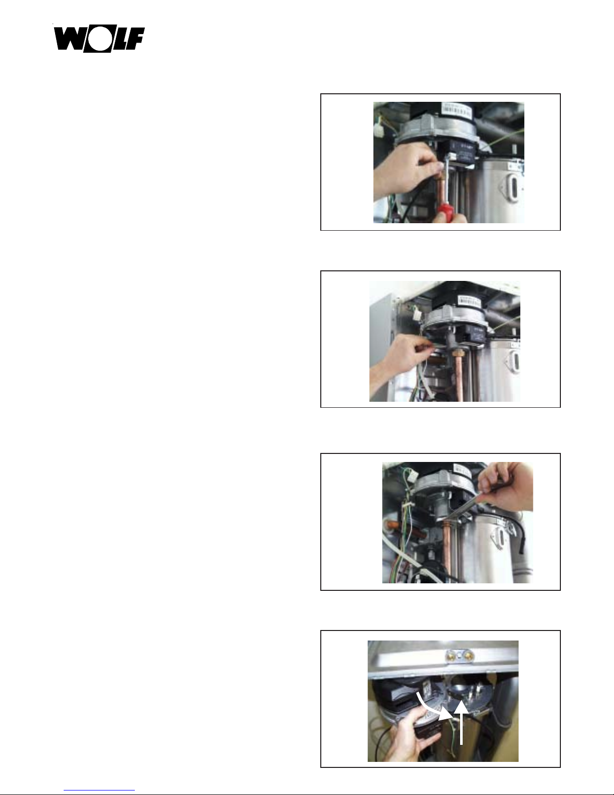
•Stecker am Zündtrafo lösen.
•Steuerleitung abziehen.
•Mischkammer-Verschraubung lösen.
•Gasgebläse nach vorne herausdrehen, hierzu Blattfeder neben Überwachungselektrode anheben.
Page 7
7
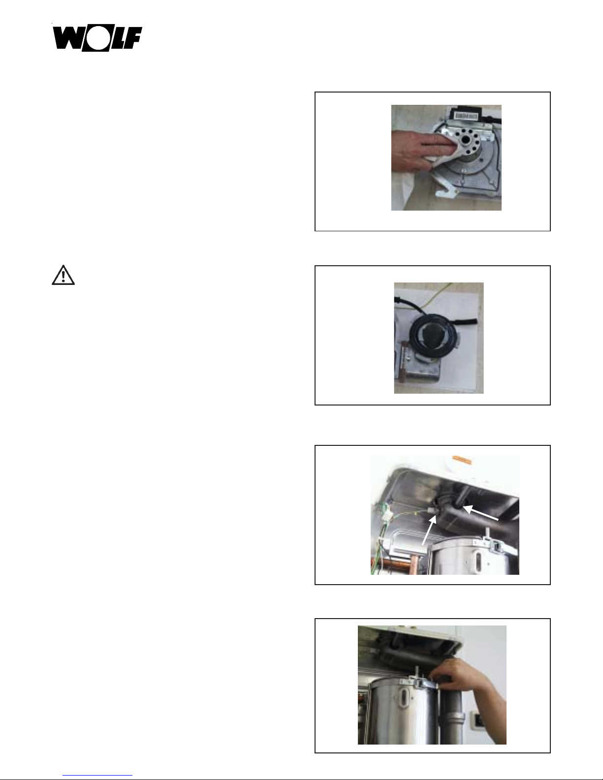
Sichtkontrolle Mischkammer
ggf. reinigen.
Sichtkontrolle Brennerdichtung
Brennerdichtung mit Wolf-Silikonfett einfetten
ggf. ersetzen und einfetten.
Sichtkontrolle Dichtungen
ggf. ersetzen und einfetten.
•Splint entfernen.
Wartungsanleitung
Page 8
8
•Brennkammer öffnen.
Sichtkontrolle Brennerdichtung
Reinigen und einfetten (Wolf-Silikonfett)
ggf. ersetzen (wenn spröde) und einfetten.
•Brenner ausbauen.
Wartungsanleitung
Sichtkontrolle Elektroden
Überwachungselektrode ersetzen
Zündelektrode ersetzen
Sichtkontrolle Isolierung
ersetzen, falls gebrochen
Sichtkontrolle Dichtung
Reinigen und einfetten (Wolf-Silikonfett)
ggf. ersetzen (wenn spröde) und einfetten.
Page 9
9
Wartungsanleitung
•Bei leichter Verschmutzung Wärmetauscher nicht
ausbauen. Reinigen, aussaugen.
Danach weiter siehe Seite 13 „Bei Kombigeräten...“ .
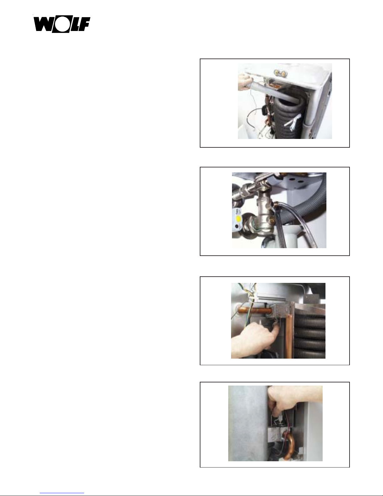
•Wasser ablassen.
•Splint im Vorlauf entfernen.
•Splint im Rücklauf entfernen.
Page 10
10
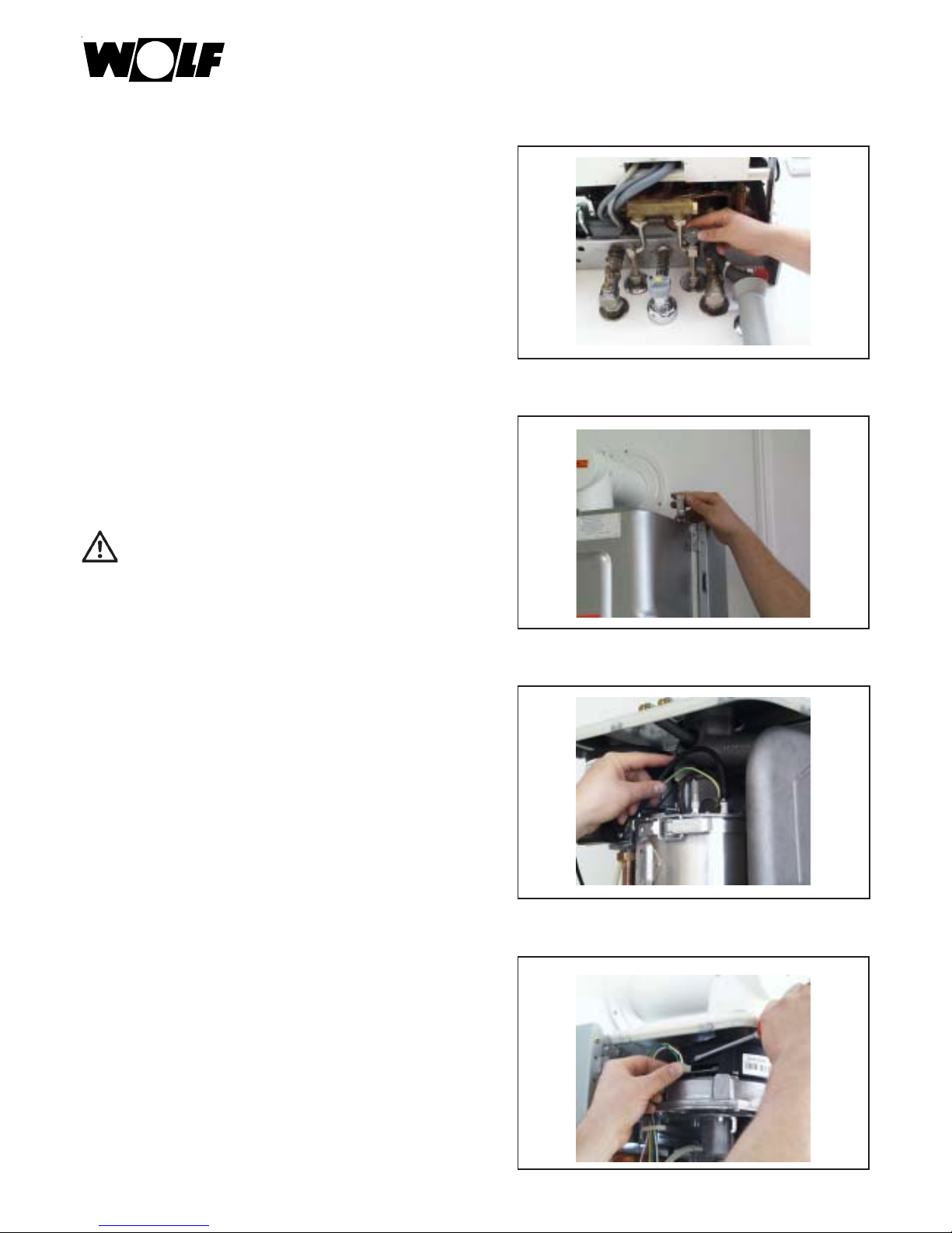
•Wärmetauscher oben nach vorne rechts ziehen.
•Wärmetauscher nach vorne herausnehmen.
Wartungsanleitung
•Wärmetauscher unten nach vorne links ziehen.
Sichtkontrolle der O-Ringe in den Anschluß-
stücken
Einfetten (Wolf-Silikonfett)
ggf. erneuern und einfetten.
Page 11
11
Wartungsanleitung
•Verdrehsicherung am Brennkammertopf nach unten
drücken.
•Brennkammertopf herausdrehen.
Sichtkontrolle Brennkammertopf
•Wärmetauscher reinigen mit Wolf-Bürste.
Page 12
12
Wartungsanleitung
•Brennkammerboden reinigen.
Zusammenbau
Sichtkontrolle Brennerdichtung
Reinigen und einfetten (Wolf-Silikonfett)
ggf. ersetzen (wenn spröde) und einfetten.
Brennkammertopf einbauen.
Wärmetauscher-Enden mit Wolf-Silikonfett einfetten.
Sichtkontrolle Wärmetauscherenden
Page 13
13
Wartungsanleitung
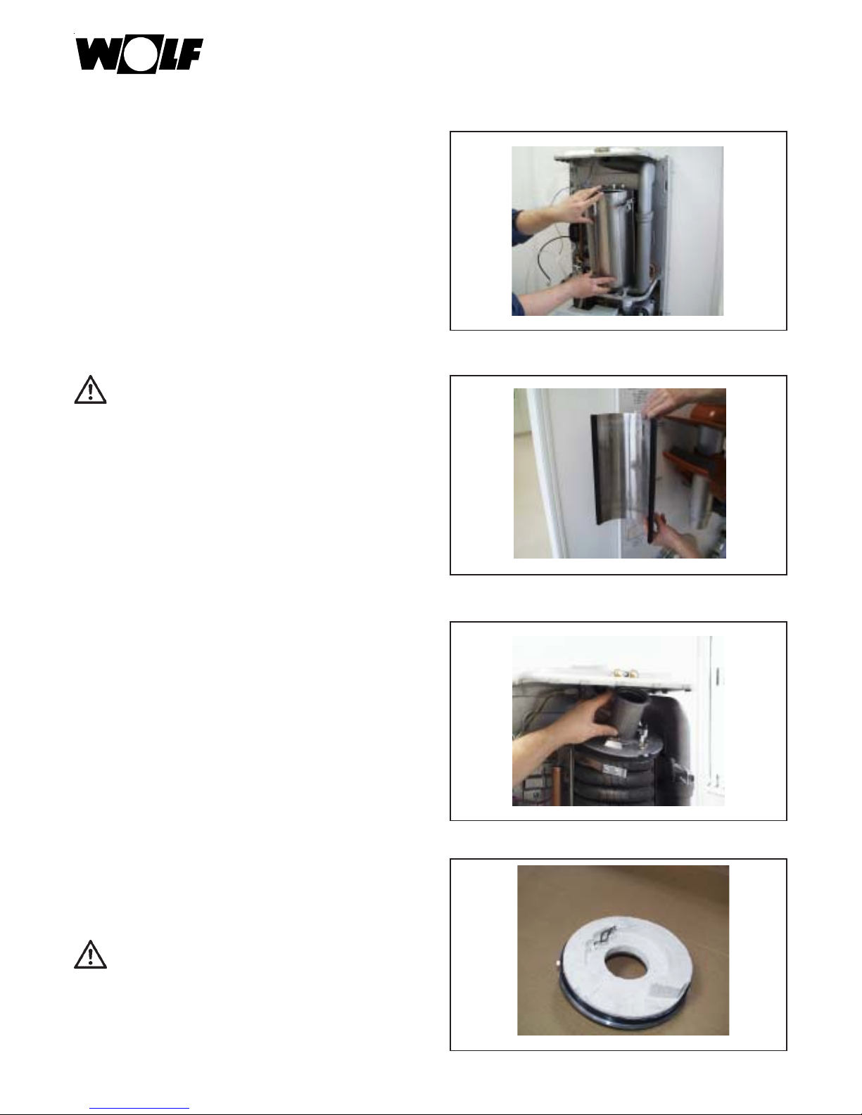
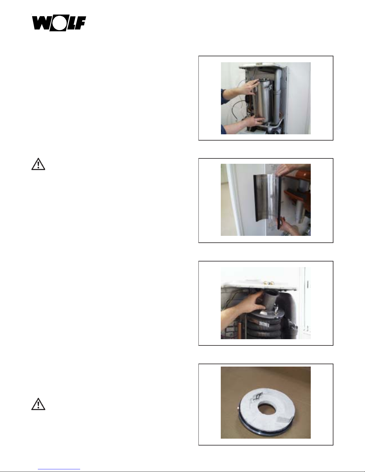
• Wärmetauscher einbauen.
Großer Windungsabstand ist
unten.
•Wärmetauscher mit den Splinten in den Anschlußstücken oben/unten sichern.
•Bei Kombigeräten ist das Kaltwassersieb zu reinigen.
• Bei Kombigeräten:
Wenn die Warmwasserleistung geringer geworden ist,
muß der Warmwasser-Wärmetauscher ausgebaut und
entkalkt werden.
Achtung
Page 14
14
Wartungsanleitung
• Vordruck vom Ausdehnungsgefäß prüfen, ggf. auf
0,75 bar erhöhen.
•Gerät füllen.
Absperrhähne und Kaltwasserhahn öffnen.
•Gerät entlüften.
• Brenner einbauen.
Page 15
15
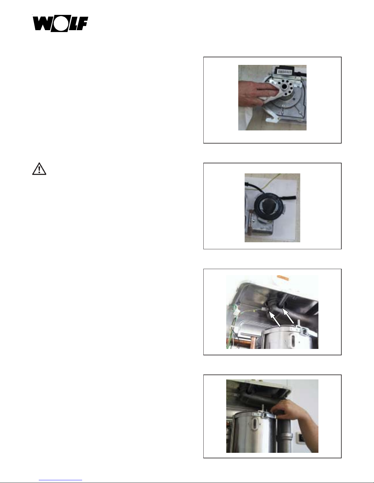
•Deckel in der Rückwand einfädeln.
•Brennkammervorderwand einbauen.
•Spannbänder schließen und oben mit Splint sichern.
Wartungsanleitung
• Ventilator montieren. Alle Kabel anschließen.
Steuerleitung an Mischerkammer anschließen.
Beim Gasanschluß an der Mischkammer neue Dichtung einsetzen.
Page 16
16
•Luft-/Abgasführung kontrollieren.
Siphon kontrollieren
Ggf. reinigen und neu füllen.
Auf festen Sitz prüfen,
Abgasaustritt verhindern.
•Brennraumgehäuse montieren.
Wartungsanleitung
Probelauf
• Sicherungen einschalten.
•Gashahn öffnen.
•Gerät einschalten.
•Programmwahlschalter auf Schornsteinfegerbetrieb
stellen.
Page 17
17
Wartungsanleitung
•Falls FC 40 erscheint, nochmals entlüften.
Dazu Wartungshahn schließen, Pumpenstecker einige Male lösen und wieder zusammen stecken.
Zuluft-Prüfung durchführen
ab CO2 > 0,2% LAF auf Dichtigkeit prüfen.
Abgasmessung bei Schornsteinfegerbetrieb
nach 5 min.
Tabelle: Empfohlener CO2-Gehalt TGB(K)-20/GB-20(-S)
Tabelle: Empfohlener CO2-Gehalt TGB-11
TGB-20 / TGB-K-20/GB-20(-S)
Erdgas E/LL Flüssiggas B/P
9,0% ±0,2% 10,2% ± 0,2%
TGB-11
Erdgas E/LL Flüssiggas P
9,2% ±0,2% 10,9% ± 0,2%
Beim Einstellen muß Parameter 4 auf maximale
Heizleistung eingestellt sein.
- Bei Bedarf den CO2-Gehalt an der Gasdurchflußschraube am Gaskombiventil durch Drehen in kleinen
Schritten (¼ Umdrehung) korrigieren.
•rechts drehen - CO2 Gehalt wird niedriger
•links drehen - CO2-Gehalt wird höher
Gasdurchflußschraube
NullpunktSchraube
Page 18

18
Wartungsanleitung
Bild: Gaskombiventil
•Programmwahlschalter auf
•Die Therme durch Drücken der “Entstörtaste” erneut
starten
•ca. 20 Sekunden nach dem Brennerstart den CO2-Gehalt mit dem CO2-Meßgerät kontrollieren und ggf. mit
Nullpunktschraube nachjustieren. Diese Einstellung
muß innerhalb von 120 Sek. nach dem Brennerstart
erfolgen. Evtl. durch Drücken der “Entstörtaste” die
Startphase zur Einstellung wiederholen.
•rechts drehen - CO2 höher!
•links drehen - CO2 niedriger!
CO2-Prüfung bei unterer Belastung
(Softstart)
•Gerät außer Betrieb nehmen und Meßöffnungen und
Schlauchanschlußnippel wieder verschließen und auf
Dichheit kontrollieren.
•Verkleidung anbringen.
Abschluß der Einstellarbeiten
TGB-20 / TGB-K-20/GB-20(-S)
Erdgas E/LL Flüssiggas B/P
8,8% bis 9,3% 10,5% bis 11,5%
TGB-11
Erdgas E/LL Flüssiggas P
8,8% bis 9,3% 10,7% bis 11,5%
Gasdurchflußschraube
NullpunktSchraube
Page 19

19
Wartungsanleitung
Regelungszubehör prüfen
•Busverbindung muß im Display zu sehen sein.
Bild: DWT Bild: AWT
Für die Wartung wird benötigt:
1 Wartungsset GB Art.-Nr. 86 02 306
1 Eine der folgenden Zündelektroden:
Zündelektrode für Erdgas bis Baujahr 05/01 Art.-Nr. 86 01 899
Zündelektrode für Flüssiggas bis Baujahr 05/01 Art.-Nr. 86 01 901
Zündelektrode für Erd- und Flüssiggas ab Baujahr 06/01 Art.-Nr. 27 96 268
1 Reinigungsbürste Art.-Nr. 24 40 053
1 Meßgerät für BImSch-Messung
Wir empfehlen, die folgenden Teile beim Serviceeinsatz mitzuführen:
1 Isolierung BK-Oberteil bis Baujahr 05/01 Art.-Nr. 86 01 868
1 Isolierung BK-Oberteil ab Baujahr 05/01 Art.-Nr. 86 02 258
1 Dichtung für Brennkammer seitlich (2 Stück) Art.-Nr. 86 02 134
1 Dichtung für Brennkammer oben/unten (2 Stück) Art.-Nr. 86 02 133
1 Dichtungsmanschette für Abgastemperaturfühler Art.-Nr. 39 03 145
1 Dichtungsmanschette für Prüfnippel Art.-Nr. 39 03 143
1 Schutzschlauch für Ionisationskabel Art.-Nr. 27 96 289
1 Fett-Silikon 10 Gramm Tube Art.-Nr. 86 02 264
oder 400 Gramm Tube Art.-Nr. 35 00 103
1 Dichtung für Brenner bis 10/99 Art.-Nr. 39 03 121
1 Dichtung für Brenner ab 11/99 Druckguß Adapter Art.-Nr. 39 03 127
1 Vorlauf-/Rücklauffühler (2 Stück) Art.-Nr. 86 01 883
1 Abgasfühler Art.-Nr. 86 01 884
1 Isolierung für Brennkammertopf Art.-Nr. 86 01 869
1 Werkzeug zum Ausbau des Heizwasserwärmetauschers Art.-Nr. 86 03 354
Weitere Teile siehe Explosionszeichnungen (bei Wolf erhältlich)
Busverbindung
Page 20

20
Wartungsanleitung
Übersicht der Arbeitsschritte mit Wartungsprotokoll
Nr. Arbeitsschritt Protokollpunkt
1 Gerät ausschalten, Notschalter aus
2 Gaszufuhr schließen,
3 Wartungshähne schließen und Wasser ablassen
4 Verkleidung und Brennraumgehäuse abnehmen
5 Elektrische Verbindungen an V entilator , Fühlern
und Elektroden abziehen
6 Mischkammer,Ventilator,
Brennerflansch ausbauen
7 Brenner ausbauen, bei Bedarf reinigen O
8 Heizwasserwärmetauscher reinigen bei Bedarf ausbauen O
9 Kondensatwanne reinigen O
10 Mischkammer bei Bedarf reinigen O
1 1 Isolierung Brennkammer auf Beschädigung prüfen O
12 Dichtungen kontrollieren, bei Bedarf wechseln und mit Silkonfett einschmieren O
13 Falls Neutralisation vorhanden, Granulat nachfüllen O
14 Bei emailliertem Speicher , Schutzanode alle 2 Jahre kontrollieren O
15 Gerät zusammenbauen
16 Siphon reinigen, füllen, montieren und auf festen Sitz achten O
17 Warmwasserwärmetauscher bei Bedarf entkalken O
18 Warmwassersieb reinigen O
19 Ausdehnungsgefäß prüfen O
20 Gerät auf 1,5 - 2,5 bar füllen und entlüften O
21 Gaszufuhr öffnen, Gerät einschalten
22 Dichtheitskontrolle Hydraulik O
23 Dichtheitskontrolle Gas O
24 Dichtheitskontrolle Abgassystem O
25 Zündung prüfen O
26 Zusammenspiel mit Regelungszubehör prüfen O
27 Abgasmessung bei Kaminkehrerbetrieb O
28 Abgastemperatur brutto °C
29 Ansauglufttemperatur °C
30 Abgastemperatur netto °C
31 Kohlendioxidgehalt (CO2) %
32 oder Sauerstoffgehalt (O2) %
33 Kohlenmonoxydgehalt (CO) %
34 Abgasverlust %
Wartung bestätigen (Firmenstempel, Unterschrift)
Datum
Page 21

21
Service Manual
Gas condensing boilers
GB-11, TGB-11
GB-20, TGB-20, GB-20-S
GB
Wolf GmbH · PO Box 1380 · 84048 Mainburg · Tel. +49 8751/74-0 · Fax +49 8751/741600 · Internet: www.wolf-heiztechnik.de
Page 22

22
Table of Contents .............................................................................................................. Page
Safety Instructions .......................................................................................................................................23
Service Procedure...................................................................................................................................24-38
List of required parts....................................................................................................................................39
Overview of work steps with service log ...............................................................................................40
Service Manual
Page 23

23
The following symbols and instruction signs are
used in this description. These important instructions
concern personal protection and technical operating
safety.
“Safety instruction” identifies instructions
that must be precisely complied with in
order to avoid personal injury and to
prevent damage to the device.
Danger - live electrical components!
Attention: Switch off the operating
switch before removing the casing.
Never touch electrical components and
contacts when the operating switch is on!
There is a danger of electrical shock resulting
in injury or death.
Voltage is also applied to terminals when the
operating switch is switched off.
“Attention” identifies technical instructions
that must be complied with in order to
prevent equipment damage and malfunctions.
Attention
Fig.: Gas connection: Toxicity hazard and explosion
hazard due to escaping gas
Fig.: Terminal box:
Electrical hazard
Fig.: Starter transformer, high-voltage starter
electrode, combustion chamber
Electrical hazard, hazard of burning injuries due to
hot components
Fig.: Gas combination valve
Electrical hazard. Toxicity hazard and explosion hazard
due to escaping gas
Service Manual
General instructions
A specialist is required for all service work.
Regular service and exclusive use of original
Wolf replacement parts are crucial for problemfree operation and long service life of your
boiler.
Consequently we recommend signing a service
contract with your service company.
Safety Instructions
Page 24

24
Service Manual
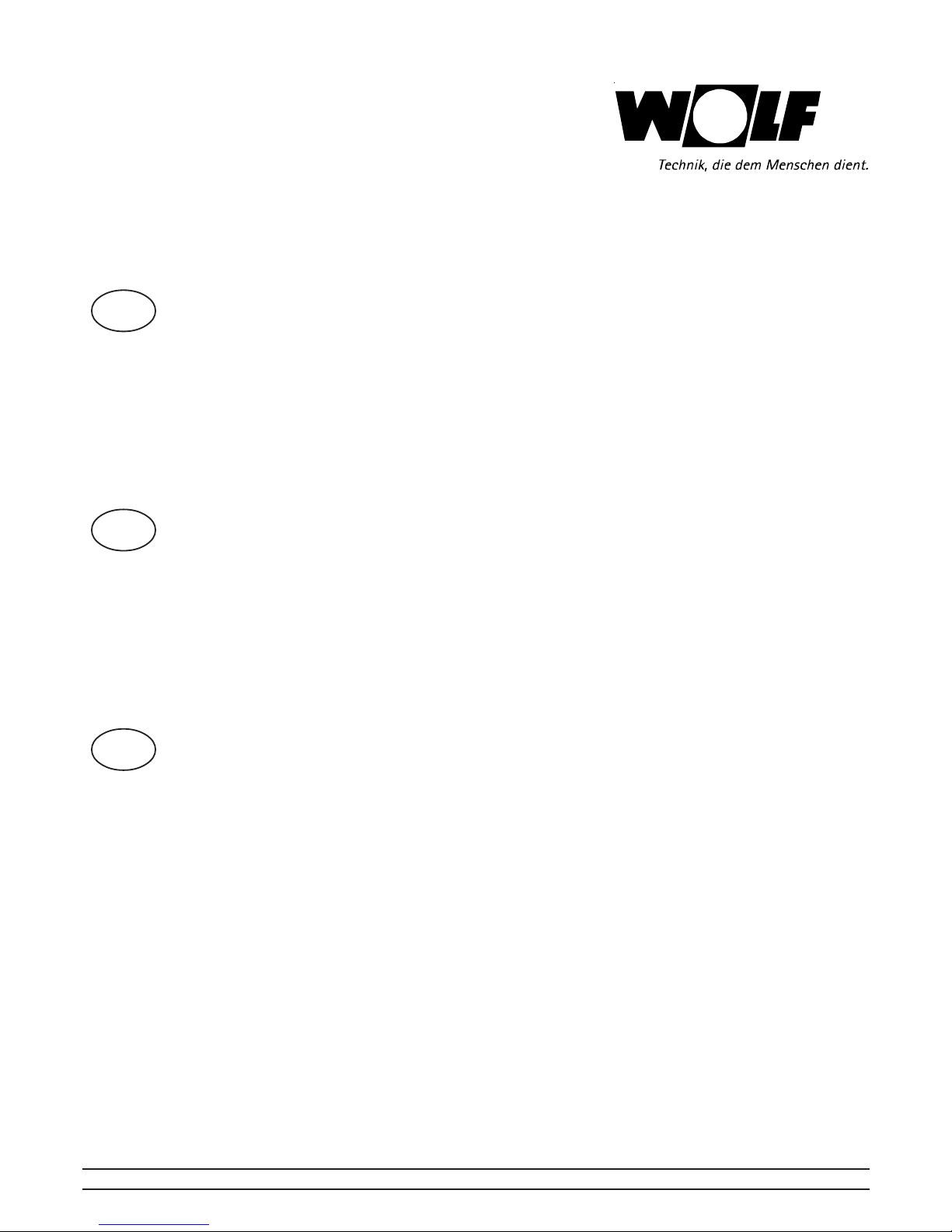
•Switch-off the boiler with the operating switch.
Electrical voltage is applied to the power
connection terminals of the device, even if
the device has been turned off.
•De-energize system.
Close gas cock.
•Shut-off heating.
Page 25
25
Service Manual
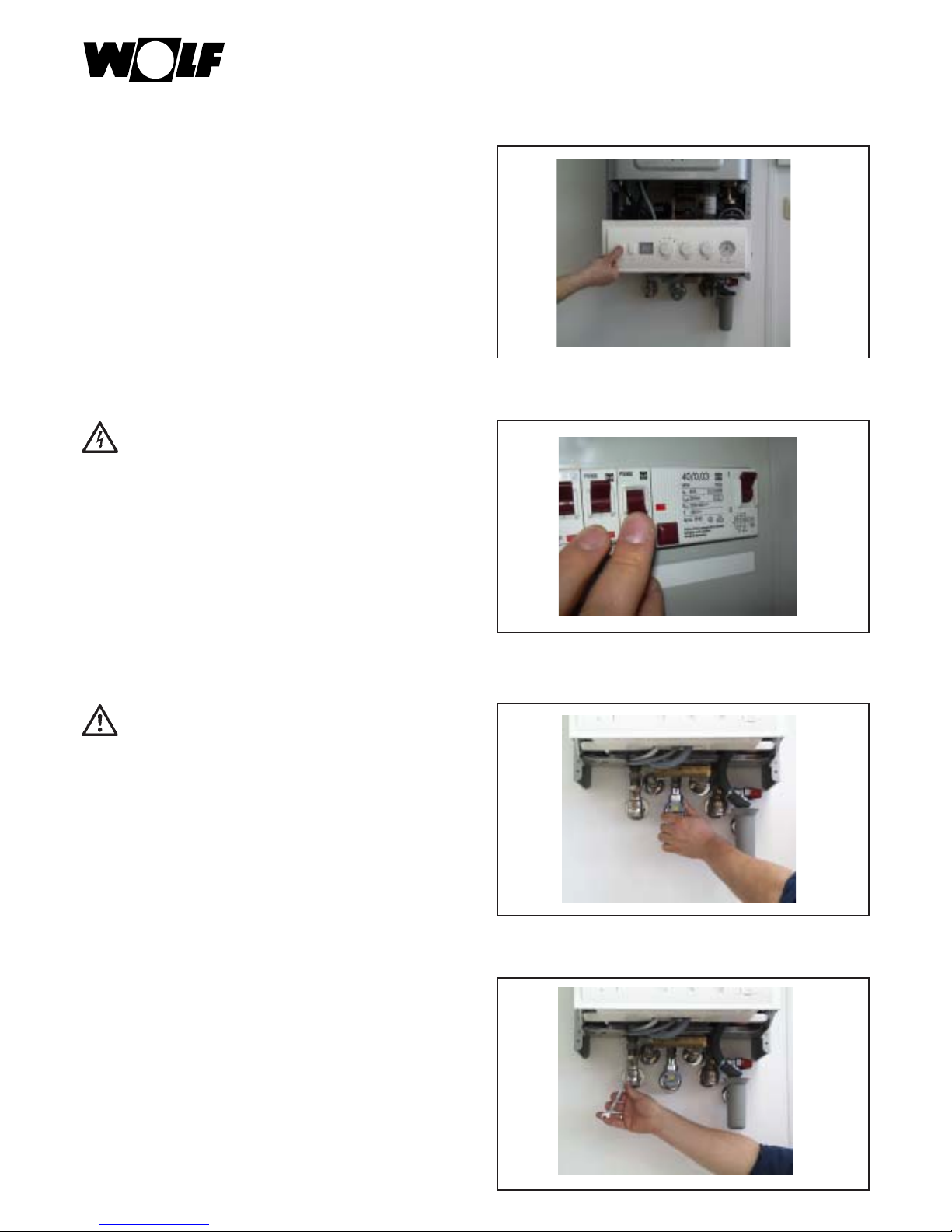
•Shut-off cold water.
•Open the combustion chamber assembly
housing.
Hazard of burn injuries
Various components can be very hot. Allow the unit
to cool or wear protective gloves.
•Remove all cables on the combustion chamber
lid
•Disconnect the plug on the gas blower.
Page 26

26
Service Manual
•Disconnect the plug on the starter transformer.
•Remove the control line.
•Loosen the mixing chamber threaded joint.
•Unscrew the gas blower from the front, to do this,
lift the leaf spring next to the monitoring electrode.
Page 27
27
Service Manual
Inspect the mixing chamber
Clean as needed.
Inspect the burner gasket
Apply Wolf silicon grease to the burner gasket,
or replace it and apply grease to the new
gasket.
Inspect gaskets
Replace and apply grease as needed.
•Remove cotter pin.
Page 28
28
Service Manual
•Open combustion chamber assembly.
Inspect the burner gasket
Clean and and apply Wolf silicon grease,
replace as needed (if brittle) and apply grease.
•Remove burner.
Inspect electrodes
Replace monitoring electrode
Replace starter electrode
Inspect insulation
replace if broken
Inspect seal
Clean and and apply Wolf silicon grease,
replace as needed (if brittle) and apply grease.
Page 29

29
Service Manual
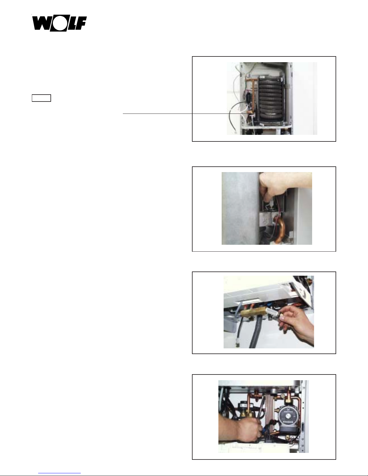
•Do not remove heat exchanger if fouling is light.
Clean and vacuum out.
Then proceed as described on page 13 “For
combination devices...“ .
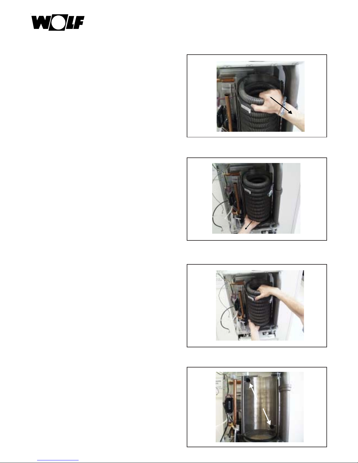
• Drain water .
•Remove cotter pin in the flow.
•Remove cotter pin in the return.
Page 30

30
Service Manual
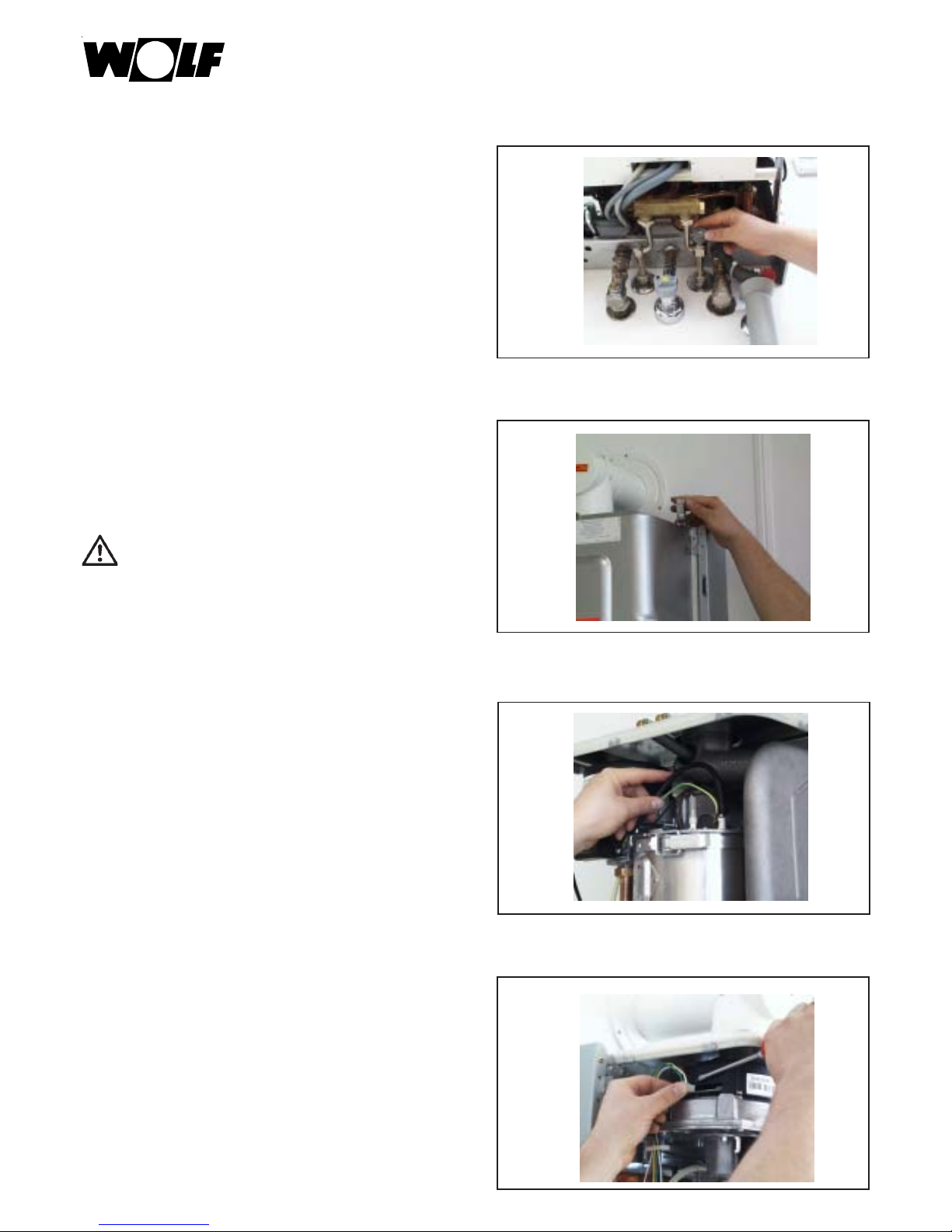
•Pull the top of the heat exchanger forwards and
to the right.
•Pull the bottom of the heat exchanger forward and
to the left.
•Pull the heat exchanger out from the front.
Check the O-rings in the connecting pieces
Apply grease (Wolf silicon grease)
Replace if needed and apply grease.
Page 31

31
Service Manual
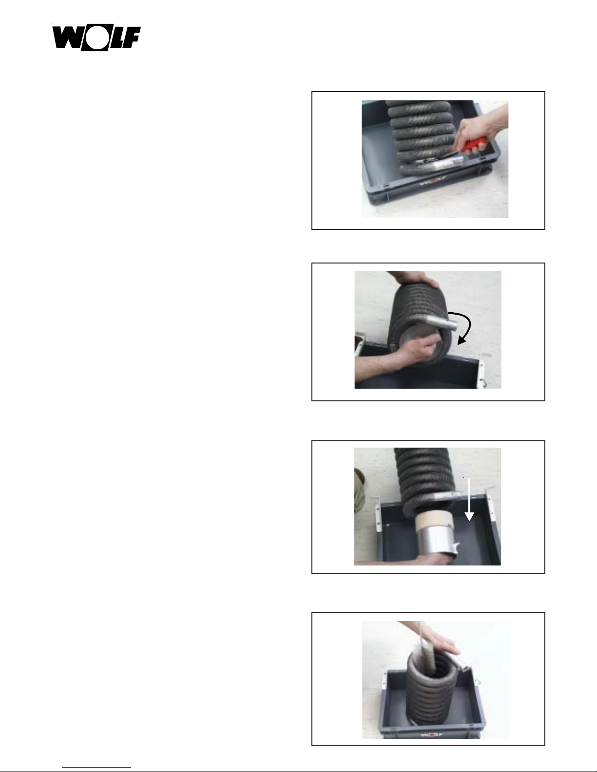
•Press the twist lock on the combustion chamber
canister downwards.
• Unscrew and remove the combustion chamber
canister .
Check the combustion chamber canister
•Clean heat exchanger with the Wolf brush.
Page 32

32
Service Manual
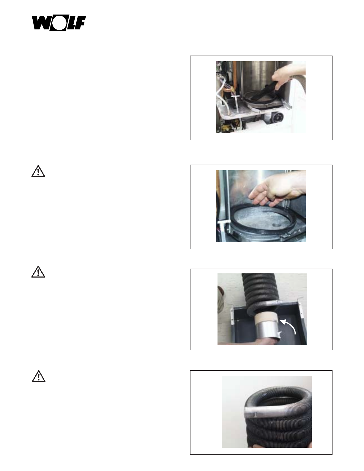
•Clean the floor of the combustion chamber.
Inspect the burner gasket
Clean and apply Wolf silicon grease
Replace as needed (if brittle) and apply grease.
Assembly
Install the combustion chamber canister .
Apply Wolf silicon grease to the ends of the
heat exchanger.
Check the ends of the heat
exchanger
Page 33

33
Service Manual
•Install heat exchanger.
Attention:
The greater distance between windings should be
down.
•Secure heat exchanger in the couplings with the
cotter pins (top/bottom).
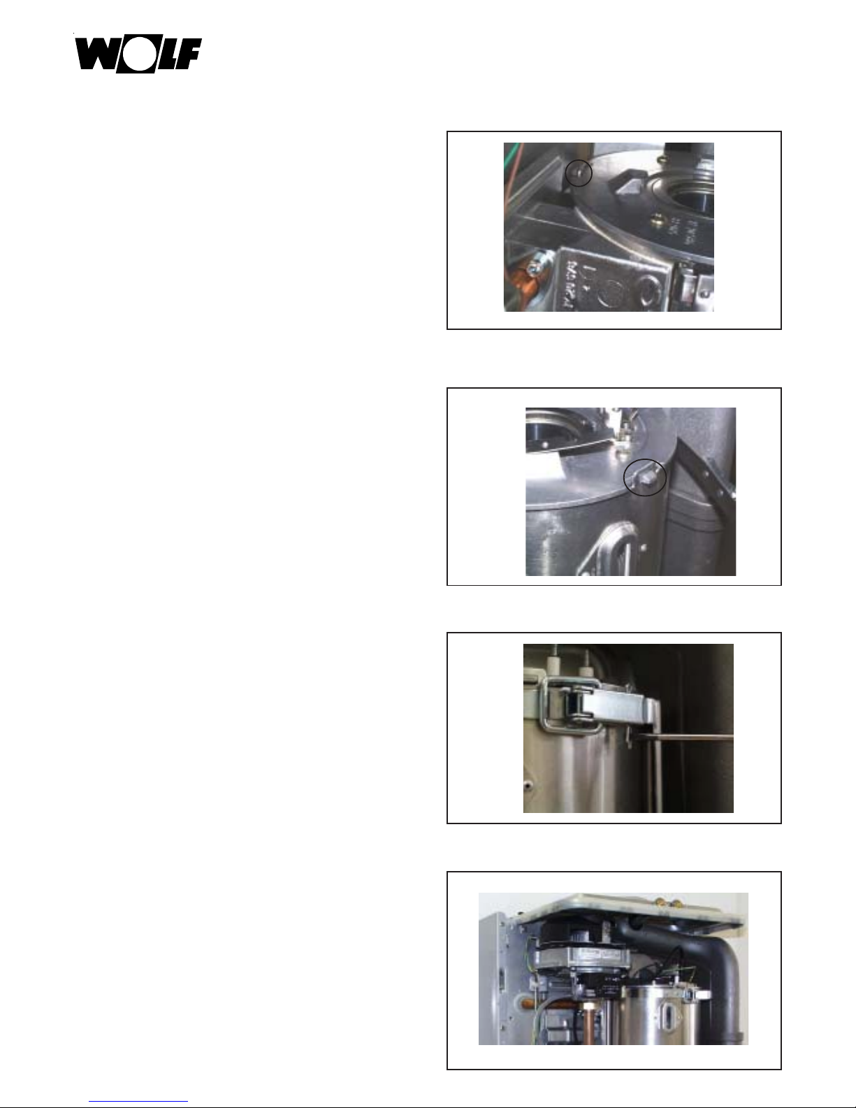
• For combination devices the cold water seive must
be cleaned.
• For combination devices:
If the hot water capacity has decreased, then the
hot water heat exchanger must be removed and
decalcified.
Page 34

34
Service Manual
•If there is water loss, then check the expansion
vessel admission pressure, increase to 0.75 bar as
needed.
•Fill device.
Open shut-off cocks and cold water cock.
•Vent device.
• Install burner .
Page 35

35
Service Manual
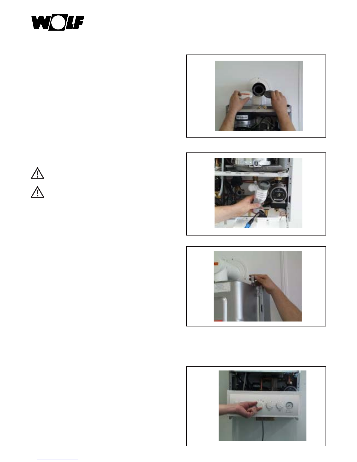
•Thread the lid into the rear wall.
•Install the combustion chamber front wall.
• Close the tightening straps and secure on top with
the cotter pin.
• Mount fan. Connect all cables.
Connect the control line to the mixing chamber.
Place a new gasket on the gas connection on the
mixing chamber.
Page 36

36
Service Manual
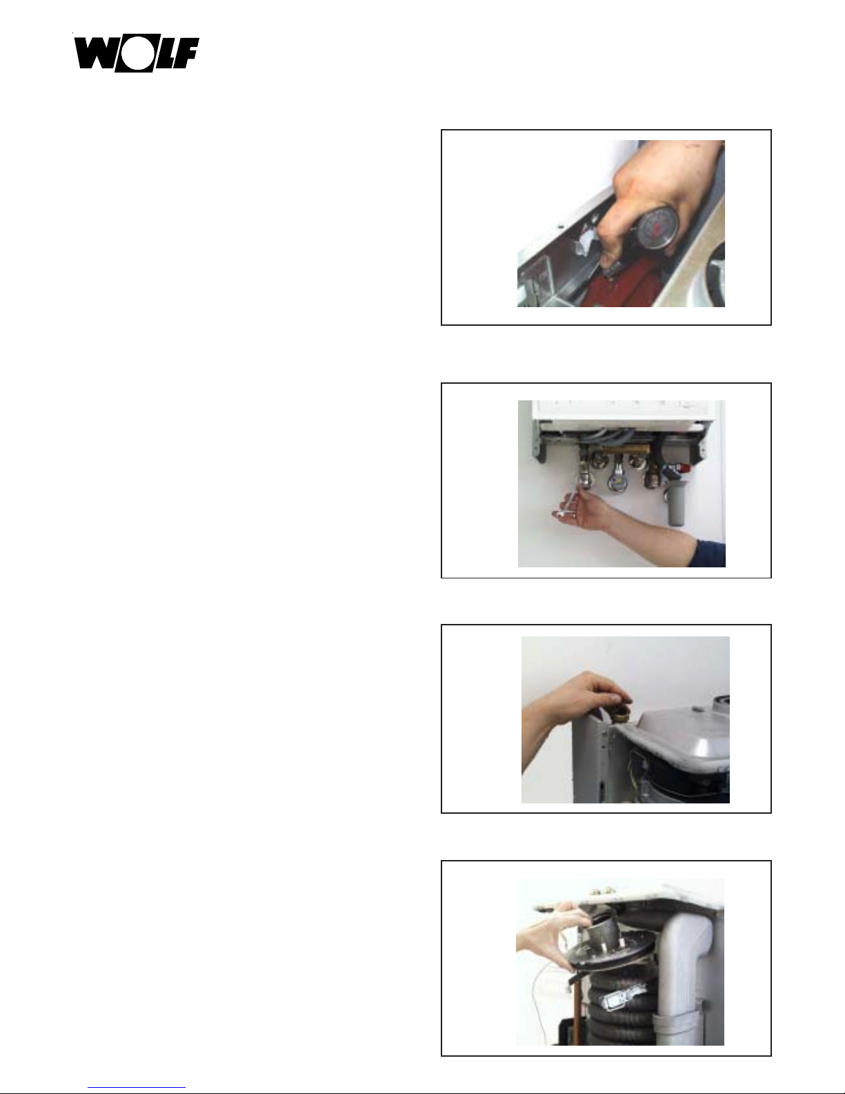
•Check the air extraction/exhaust gas extraction.
Check the siphon
Clean as needed and refill.
Check for firm seat.
Prevent exhaust gas escape.
•Mount the combustion chamber housing.
Trial run
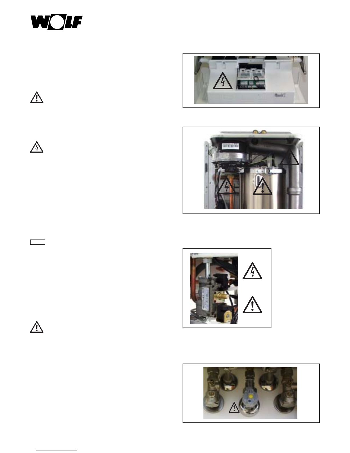
• Turn on the fuses.
•Open the gas cock.
•Switch on the device.
•Set the program selector switch to chimney-sweep
mode.
Page 37

37
Service Manual
Measure the exhaust gas in chimney
sweep mode after 5 minutes.
Table: Recommended CO2 content TGB(K)-20/GB-20(-S)
Table: Recommended CO2 content TGB-11
When adjusting, parameter 4 must be set on
maximum heating power.
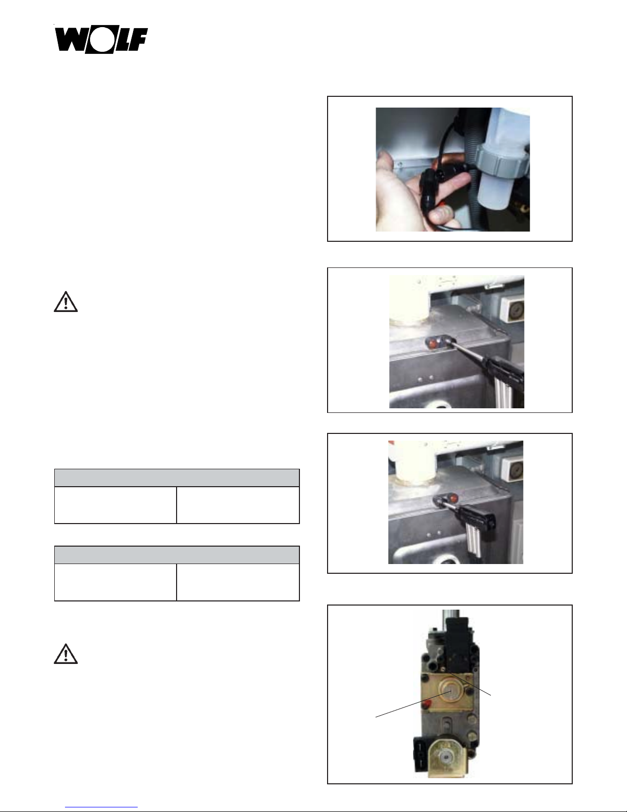
- Correct the CO2 content using the gas flow screw
on the gas combination valve as needed by turning
in small increments (1/4 turn).
•Turn to the right - CO2 content is decreased
•Turn to the left - CO2 content is increased
Gas flow screw
Zero-point
screw
TGB-20 / TGB-K-20/GB-20(-S)
Natural gas E/LL Liquified petroleum gas B/P
9,0% ±0,2% 10,2% ± 0,2%
TGB-11
Natural gas E/LL Liquified gas P
9,2% ±0,2% 10,9% ± 0,2%
•If VC 40 appears, then vent again.
Close the service cock for this, disconnect the
pump plug and reconnect it several times.
Perform intake air test
If CO2 > 0.2% then check LA for leaks.
Page 38

38
Service Manual
Fig: Gas combination valve
•Program selector switch on
•Restart the boiler by pressing the “Suppress button“ .
•App. 20 seconds after the burner starts, check the
CO2 content with the CO2 measuring device and
readjust as needed with the zero-point screw. This
setting must be made within 120 sec. after the
burner starts. If needed repeat the start phase in
order to make the setting by pushing the “Suppress“
button.
•Turn to the right - CO2 increases!
•Turn to the left - CO2 decreases!
CO2 test at lower charging (soft start)
• Take device out of service; reseal measurement
openings and hose connection nipple, and check
for leaks.
•Replace cover.
Setting work is completed
TGB-20 / TGB-K-20/GB-20(-S)
Natural gas E/LL Liquified petroleum gas B/P
8.8% to 9.3% 10.5% to 11.5%
TGB-11
Natural gas E/LL Liquified gas P
8.8% to 9.3% 10.7% to 11.5%
Gas flow screw
Zero-point
screw
Page 39

39
Service Manual
Check control accessories
•Bus connection must be shown in the display.
Fig: DWT Fig: AWT
The following is required for service:
1 Service set GB Item no. 86 02 306
1 One of the following starter electrodes:
Starter electrode for natural gas to model year 05/01 Item no. 86 01 899
Starter electrode for liquified gas to model year 05/01 Item no. 86 01 901
Starter electrode for natural gas and liquified gas from model year 06/01 Item no. 27 96 268
1 Cleaning brush Item no. 24 40 053
1 Measuring device for Federal Emission Control Law measurement
We recommend having the following parts on hand when making a service call:
1 Combustion chamber upper part insulation to model year 05/01 Item no. 86 01 868
1 Combustion chamber upper part insulation from model year 05/01 Item no. 86 02 258
1 Lateral seal for combustion chamber (2 units) Item no. 86 02 134
1 Seal for combustion chamber up/down (2 units) Item no. 86 02 133
1 Sealing sleeve for exhaust gas temperature sensor Item no. 39 03 145
1 Sealing sleeve for test nipple Item no. 39 03 143
1 Protective hose for ionization cable Item no. 27 96 289
1 Tube of silicon grease 10 gram tube Item no. 86 02 264
or 400 gram tube Item no. 35 00 103
1 Seal for burner to 10/99 Item no. 39 03 121
1 Seal for burner from 11/99 die-cast adapter Item no. 39 03 127
1 Flow/return sensor (3 units) Item no. 86 01 883
1 Exhaust gas sensor Item no. 86 01 864
1 Insulation for combustion chamber canister Item no. 86 01 869
1 Tool for removing the hot water heat exchanger Item no. 86 03 354
See the explosion drawing for additional parts (available from Wolf)
Bus connection
Page 40

40
Service Manual
Overview of work steps with service log
No. Work step Log item
1 Switch off device, Emergency-switch off
2 Close gas feed,
3 Close service cocks and drain water
4 Remove cover and combustion area housing
5 Remove the electrical connections on the fan, sensors
and electrodes
6 Remove mixing chamber, fan, burner flange
7 Remove burner, clean as needed
8 Clean hot water heat exchanger, clean as needed O
9 Clean condensate sump O
10 Clean mixing chamber as needed O
1 1 Check combustion chamber insulation for damage O
12 Check seals, replace as needed and apply silicon grease O
13 If neutralization is present, refill with granulate O
14 For enameled hot water storage, check magnesium sacrificial anode every 2 years O
15 Reassemble device
16 Clean siphon, fill, mount, and ensure firm seat O
17 Decalcify hot water heat exchanger as needed O
18 Clean hot water sieve O
19 Check expansion vessel O
20 Fill device to 1.5 - 2.5 bar and vent O
21 Open gas feed, switch device on
22 Check hydraulics for leaks O
23 Check for gas leaks O
24 Check for exhaust system leaks O
25 Check starter O
26 Check the interplay with control accessory O
27 Measure exhaust gas in chimney sweep mode O
28 Gross exhaust gas temperature ° C
29 Intake air temperature °C
30 Net exhaust gas temperature ° C
31 Carbon dioxide content (CO2) %
32 or oxygen content (02) %
33 Carbon monoxide content (CO) %
34 Exhaust gas loss %
Confirm service (company stamp, signature)
Date
Page 41

41
Istruzioni per la manutenzione
Caldaie murali a condensazione
GB-11, TGB-11
GB-20, TGB-20, GB-20-S
I
Wolf GmbH · Postfach 1380 · 84048 Mainburg · Tel. 08751/74-0 · Fax 08751/741600 · Internet: www.wolf-heiztechnik.de
Page 42

42
Indice.................................................................................................................................pagina
Avvertenze per la sicurezza....................................................................................................................... 43
Operazioni da eseguire.........................................................................................................................44-58
Elenco parti necessari per la manutenzione ........................................................................................59
Vista d‘insieme degli operazioni con protocollo di manutenzione.............................................. 6 0
Istruzioni per la manutenzione
Page 43

43
Attenzione
Figura: attacco gas: pericolo di intossicazione e di
esplosione per fuoriuscita di gas
Figura: morsettiera:
Pericolo a causa di tensione elettrica
Figura: trasformatore d‘accensione, elettrodo di
accensione ad alta tensione, camera di combustione,
pericolo a causa di tensione elettrica e scottature per
componenti riscaldati.
Figura: valvola gas combinata
Pericolo a causa di tensione elettrica
Pericolo di intossicazione e di esplosione per
fuoriuscita di gas
Istruzioni di montaggio
In questo manuale vengono utilizzati i seguenti simboli
e segnali d‘avvertenza che riguardano la protezione
delle persone e la sicurezza tecnica durante il
funzionamento dell‘impianto.
Il simbolo „avvertenza di sicurezza“ indica
della prescrizioni che devono essere osservate
scrupolosamente per evitare l‘eventuale
comparsa di pericoli o ferite alle persone
oppure danni all‘apparecchio.
Pericolo a causa della tensione elettrica sui
componenti elettrici!
Attenzione: spegnere l‘interruttore generale
prima di togliere il mantello.
Non toccare mai i componenti ed i contatti
elettrici con l‘interruttore generale acceso!
Esiste il pericolo di scosse elettriche con danni
per la salute oppure la morte.
I morsetti sono sotto tensione anche con
l‘interruttore generale caldaia spento.
"Avvertenza" indica delle istruzioni tecniche
che devono essere osservate per evitare dei
danni o problemi di funzionamento
sull‘apparecchio.
Avvertenze per la sicurezza
Avvertenze generali
Tutti i lavori di manutenzione devono essere
eseguiti soltanto da parte del tecnico specializzato.
La manutenzione regolare così come anche
l‘utilizzo di soli ricambi originali Wolf, sono
determinanti per il corretto funzionamento e per
la lunga durata dell‘apparecchio. Consigliamo di
stipulare un contratto di manutenzione con il
tecnico autorizzato.
Richiamiamo l‘attenzione sulla manutenzione
annuale che, oltre ad essere consigliata dal
costruttore, è prescritta dal DPR 412/93 modificato
con DPR 551/99.
Page 44

44
Istruzioni per la manutenzione
•Chiudere il rubinetto caldaia.
Chiudere il rubinetto del gas.
La morsettiera della caldai è sotto tensione
anche con l‘interruttore del pannello spento.
•Togliere la tensione all‘impianto dall‘interruttore
generale.
•Spegnere la caldaia tramite l‘interruttore del
pannello di controllo.
Page 45

45
Istruzioni per la manutenzione
•Chiudere il rubinetto dell‘acqua fredda.
•Aprire la camera di combustione.
Pericolo di scottature
Alcuni componenti possono riscaldarsi molto. Lasciare
raffreddare oppure utilizzare dei guanti.
•Togliere tutti i connettori dei cavi dal coperchio
della camera di combustione.
•Togliere i connettori del ventilatore.
Page 46

46
Istruzioni per la manutenzione
•Estrarre il ventilatore tirandolo in avanti e alzando
la molla a balestra posta vicino all‘elettrodo di
rilevazione.
•Svitare le viti della camera di miscelazione.
•Togliere i connettori degli elettrodi.
•Togliere i connettori del trasformatore di
accensione.
Page 47

47
Istruzione per la manutenzione
Controllo visivo camera di miscelazione
Se necessario, effettuare la pulizia
Controllo visivo
guarnizione bruciatore
Lubrificare le guarnizioni del bruciatore con
il grasso siliconico Wolf,eventualmente
sostituirle e lubrificarle.
Controllo visivo guarnizioni
eventualmente sostiture e lubrificare con il grasso
siliconico Wolf.
•Togliere la molla di fissaggio.
Page 48

48
Istruzioni per la manutenzione
Controllo visivo elettrodi
Sostituire l‘elettrodo di rilevazione
Sostituire l‘elettrodo di accensione
Controllo visivo isolamento
sostituire nel caso in cui fosse danneggiato
Controllo visivo guarnizione
Pulire e lubrificare con il grasso siliconico
Wolf ed eventualmente sostituire (se fosse fragile) e lubrificare.
•Smontare il bruciatore.
Controllo visivo
guarnizione camera di combustione
Pulire e lubrificare con il grasso siliconico
Wolf ed eventualmente sostituirle (se sono
fragili) e lubrificare con il grasso siliconico
Wolf.
•Aprire la camera di combustione.
Page 49

49
Istruzioni per la manutenzione
•Togliere la molla della sonda ritorno.
• Togliere la molla della sonda mandata.
•Scaricare l‘acqua.
•In caso di sporco leggero, non smontare lo
scambiatore secondario. Effettuare la pulizia e
l‘aspirazione.
Dopodichè, consultare la pagina 13 „in caso di
caldaie con produzione di acqua sanitaria...“ .
Page 50

50
Istruzioni per la manutenzione
•Tirare lo scambiatore secondario in alto verso la
parte destra.
•Tirare lo scambiatore secondario in basso verso la
parte sinistra.
• Estrarre lo scambiatore secondario tirandolo in
avanti.
Controllo visivo degli O-Ring nei raccordi
Lubrificare con il grasso siliconico Wolf
Eventualmente sostituire e lubrificare con il grasso
siliconico.
Page 51

51
Istruzioni per la manutenzione
• Premere la sicurezza antitorsione del tampone
refrattario della camera di combustione verso il
basso.
•Ruotare il tampone della camera di combustione
ed estrarlo verso il basso.
Controllo visivo tampone
camera di combustione
•Pulire lo scambiatore secondario con l‘apposita
spazzola prevista da Wolf.
Page 52

52
Istruzioni per la manutenzione
•Pulire il fondo della camera di combustione.
Controllo visivo guarnizione
camera di combustione
Pulire e lubrificare con il grasso siliconico
Wolf oppure eventualmente sostituire (se
fosse fragile) e lubrificare con il grasso
siliconico previsto da Wolf.
Lubrificare i terminali dello scambiatore con
il grasso siliconico previsto da Wolf,
controllare che la sede della clip non sia
danneggiata.
Controllo visivo attacchi
scambiatore alettato
Montaggio
Montare il tampone refrattario della camera
di combustione.
Page 53

53
Istruzioni per la manutenzione
•Montare lo scambiatore alettato.
Attenzione:
La distanza grande delle spire
deve essere posizionata sulla parte bassa.
• Assicurare lo scambiatore con le molle nei raccordi
superiori/inferiori.
• In caso di caldaie con produzione di acqua sanitaria
deve essere pulito il filtro dell‘acqua fredda,
posizionato sul relativo collettore idraulico.
• Solo con caldaie combinate:
Se la produzione dell‘acqua sanitaria dovesse
risultare troppo bassa, eseguire il lavaggio dello
scambiatore secondario oppure sostituirlo.
Page 54

54
Istruzioni di manutenzione
• Controllare la pressione di precarica del vaso
d‘espansione, se inferiore a 0,75 bar, riportarla ai
valori di fabbrica. Durante questa operazione il
circuito deve essere scaricato.
•Caricare la caldaia.
Aprire lentamente i rubinetti di intercettazione ed
il rubinetto dell‘acqua fredda.
•Disaerare accuratamente la caldaia.
• Montare il bruciatore.
Page 55

55
Istruzioni per la manutenzione
•Inserire il coperchio sul retro.
• Montare la parte anteriore della camera di
combustione ed innestarla nell‘apposita sede.
• Innestare e chiudere i ganci, assicurando quello in
alto con la molla.
• Montare il ventilatore. Collegare tutti i cavi.
Collegare il tubetto in silicone nella camera di
miscelazione.
Durante il collegamento tubo gas, inserire una
nuova guarnizione sulla camera di miscelazione.
Page 56

56
Istruzioni per la manutenzione
Prova funzionamento
• Dare tensione.
•Aprire il rubinetto del gas.
•Accendere la caldaia.
•Posizionare il selettore programmi
sul funzionamento „spazzacamino“.
•Montare la camera di combustione.
Controllare il sifone
Se necessario, pulirlo e riempirlo di nuovo.
Controllare la tenuta, evitare la fuoriuscita dei
fumi.
•Controllare il sistema di scarico aria/fumi.
Page 57

57
Istruzioni per la manutenzione
•Se dovesse essere visualizzato il codice errore 40,
disaerare nuovamente, chiudendo il rubinetto della
manutenzione, staccare i connettori della pompa
per alcune volte e riconnetterli.
Verifica sull‘aria comburente
Inserendo il sensore fumi nella presa aria
comburente, se la CO2 > 0,2%, controllare la
tenuta del sistema scarico/fumi.
Analisi fumi durante il funzionamento
„spazzacamino“ dopo 5 minuti
Tabella: tenore CO2 consigliato TGB(K)-20/GB-20(-S)
Tabella: tenore CO2 consigliato TGB-11
TGB-20 / TGB-K-20/GB-20(-S)
Gas metano E Gas liquido B/P
9,0% ±0,2% 10,2% ± 0,2%
TGB-11
Gas metano E Gas liquido P
9,2% ±0,2% 10,9% ± 0,2%
Durante la regolazione, il parametro 4 deve
essere impostato alla potenza max.
riscaldamento.
- Se necessario, regolare il tenore CO2 sulla vite
portata gas della valvola gas, ruotando lentamente
(¼ giro).
•ruotando a destra - riduzione tenore CO2
•ruotando a sinistra - aumento tenore CO2
Vite portata
gas
Vite punto zero
Page 58

58
Istruzioni per la manutenzione
Figura: valvola gas
• Posizionare il selettore programmi su questo
simbolo
• Riaccendere la caldaia premendo il tasto „reset/
ripristino“
•Ca. 20 secondi dopo l‘accensione del bruciatore,
controllare il tenore CO2 con l‘analizzatore fumi
ed eventualmente regolare la combustione con la
vite punto zero secondo la tabella riportata sotto.
Questa regolazione deve essere effettuata entro 120
secondi dopo l‘accensione del bruciatore.
Premendo il tasto di ripristino, è possibile ripetere
la regolazione della CO2 .
•ruotando a destra - aumento CO2!
•ruotando a sinistra - riduzione CO2!
Regolazione tenore CO2 alla potenza min.
(softstart)
•Spegnere l‘apparecchio e chiudere i tappi fumi/aria
e controllare la tenuta del circuito fumi ed aria.
•Montare il mantello.
Termine della prova
TGB-20 / TGB-K-20/GB-20(-S)
Gas metano E Gas liquido B/P
8,8% bis 9,3% 10,5% bis 11,5%
TGB-11
Gas metano E Gas liquido P
8,8% bis 9,3% 10,7% bis 11,5%
Vite portata
gas
Vite punto zero
Page 59

59
Istruzioni per la manutenzione
Controllo delle
termoregolazioni Wolf fornite
(accessori)
• Deve essere visualizzato sul Display il simbolo
collegamento bus , il quale indica il corretto
collegamento Bus tra la caldaia ed il regolatore.
Figura: DWT Figura: AWT
Accessori necessari per la manutenzione:
1 Kit di manutenzione GB Codice 86 02 306
1 Uno dei seguenti elettrodi di accensione:
Elettrodo di accensione per gas metano fino ad anno di costruzione 05/01 Codice 86 01 899
Elettrodo di accensione per gas liquido fino ad anno di costruzione 05/01 Codice 86 01 901
Elettrodo di accensione per gas metano e gas liquido fino da anno di costr. 06/01 Codice 27 96 268
1 Spazzola per la pulizia Codice 24 40 053
1 Analizzatore fumi
Consigliamo di portare i seguenti pezzi per effettuare la manutenzione:
1 Isolamento parte superiore camera di combustione fino ad anno di costr. 05/01 Codice 86 01 868
1 Isolamento parte superiore camera di combustione da anno di costruzione 05/01 Codice 86 02 258
1 Guarnizioni per parte laterale camera di combustione (2 pezzi) Codice 86 02 134
1 Guarnizioni per parte superiore/inferiore camera di combustione (2 pezzi) Codice 86 02 133
1 Guarnizione anello di tenuta per sonda fumi Codice 39 03 145
1 Guarnizione anello di tenuta per presa misurazione Codice 39 03 143
1 Flessibile di protezione per cavi d‘ionizzazione Codice 27 96 289
1 Grasso siliconico tubetto 10 grammi Codice 86 02 264
tubetto 400 grammi Codice 35 00 103
1 Guarnizione per bruciatore fino a10/99 Codice 39 03 121
1 Guranizione per bruciatore da11/99 adattatore pressofuso Codice 39 03 127
1 Sonde di mandata/di ritorno (2 pezzi) Codice 86 01 883
1 Sonda fumi Codice 86 01 884
1 Isolamento per il tampone camera di combustione Codice 86 01 869
1 Attrezzi per lo smontaggio dello scambiatore secondario Codice 86 03 354
Per altri parti vedi i relativi esplosi (disponibili da Wolf)
collegamento Bus
Page 60

60
Istruzioni per la manutenzione
Vista d‘insieme delle operazioni da eseguire e protocollo di manutenzione, queste sono le operazioni consigliate per mantenere una
efficienza della caldaia. La manutenzione è regolata da norme e leggi specifiche alle quali ci si deve attenere scrupulosamente.
N° Operazione Punto del protocollo
1 Spegnere l‘apparecchio, spegnere l‘interruttore d‘emergenza
2 Chiudere l‘alimentazione gas
3 Chiudere i rubinetti manutenzione e scaricare l‘acqua
4 Togliere il mantello ed il coperchio della camera di combustione
5 Togliere i collegamenti elettrici sul ventilatore, sulle sonde e sugli elettrodi
6 Smontare la camera di miscelazione, il ventilatore
e la flangia bruciatore
7 Smontare il bruciatore, in caso di necessità pulirlo O
8 Pulire lo scambiatore primario, in caso di necessità smontarlo O
9 Pulire la vasca della condensa O
10 In caso di necessità, pulire la camera di miscelazione O
11 Controllare l‘isolamento della camera di combustione ad eventuali danni O
12 Controllare le guarnizioni, in caso di necessità sostituirli e cospargere con grasso siliconico O
13 Se è montato un neutralizzatore, caricare i granulati O
14 Con il bollitore smaltato, controllare l‘anodo di protezione ogni 2 anni O
15 Rimontare l‘apparecchio
16 Pulire il sifone, caricarlo, montarlo facendo attenzione alla perfetta tenuta O
17 Se necessario, eliminare il calcare dallo scambiatore secondario O
18 Pulire il filtro dell‘acqua calda O
19 Controllare la precarica del vaso di espansione O
20 Caricare la caldaia ad una pressione di 1,5 - 2,5 bar e disaerare O
21 Aprire l‘alimentazione gas, accendere la caldaia
22 Controllo tenuta parte idraulica O
23 Controllo tenuta gas O
24 Controllo tenuta sistema di scarico fumi O
25 Controllo sistema d‘accensione O
26 Controllo funzionamento accessori di regolazione (sonde, servomotori) O
27 Analisi fumi con funzionamento „spazzacamino“ (potenza max.) O
28 Temperatura fumi lorda °C
29 Temperatura aria comburente °C
30 Temperatura fumi netta °C
31 Tenore anidride carbonica (CO2) %
32 oppure tenore ossigeno (O2) %
33 Tenore ossido di carbonio (CO) %
34 Perdite di calore al camino %
Conferma manutenzione (timbro CAT , firma)
Data
 Loading...