


PRO WALL HOOD
INSTALLATION GUIDE
SPECIFICATIONS, INSTALLATION, AND MORE

PRO WALL HOOD
Contents
3 Pro Wall Hood
4 Safety Precautions
5 Specications
9 Installation
14 Blower Specications
15 Troubleshooting
Features and specications are subject to change at any
time without notice. Visit wolfappliance.com/specs for the
most up-to-date information.
2 | Wolf Customer Care 800.222.7820
PRO WALL HOOD
Important Note
To ensure this product is installed and operated as safely
and efciently as possible, take note of the following types
of highlighted information throughout this guide:
IMPORTANT NOTE highlights information that is especially
important.
CAUTION indicates a situation where minor injury or product
damage may occur if instructions are not followed.
WARNING states a hazard that may cause serious injury or
death if precautions are not followed.
IMPORTANT NOTE: Throughout this guide, dimensions in
parentheses are millimeters unless otherwise specied.
IMPORTANT NOTE: Save these instructions for the local
electrical inspector.
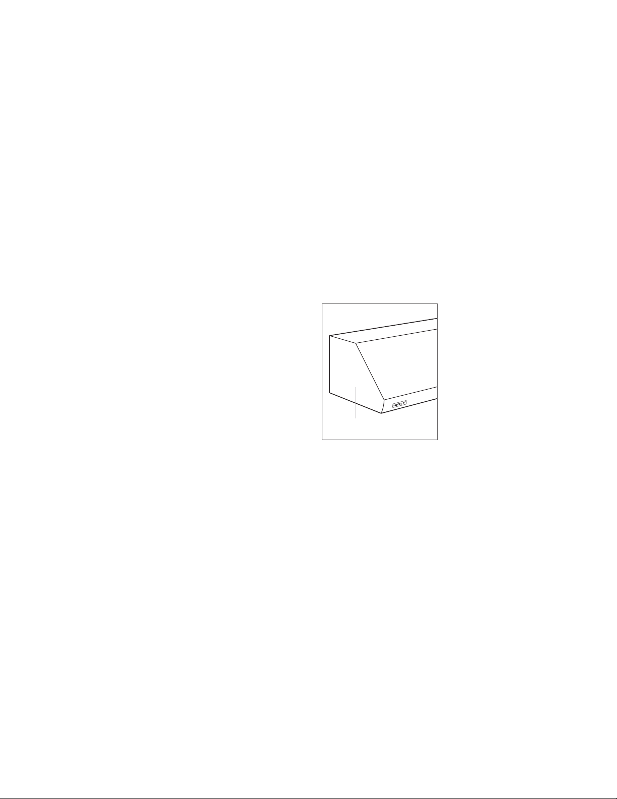
Product Information
Important product information, including the model and
serial number, are listed on the product rating plate. The
rating plate is located inside the left wall of the hood shell.
Refer to the illustration below.
If service is necessary, contact Wolf Factory Certied
Service with the model and serial number. For the name of
the nearest Wolf Factory Certied Service or for questions
regarding the installation, visit the contact and support
section of our website, wolfappliance.com, or call Wolf
Customer Care at 800-222-7820.
RATING PLATE
Rating plate location
wolfappliance.com | 3

SAFETY PRECAUTIONS
IMPORTANT INSTRUCTIONS
TO REDUCE THE RISK OF FIRE, ELECTRIC SHOCK,
OR INJURY, OBSERVE THE FOLLOWING:
• Installation work and electrical wiring must be
done by qualied person(s) in accordance with all
applicable codes and standards, including rerated construction.
• Two installers are recommended due to the size
and weight of the pro hood.
• Install the pro hood only with a blower manufac-
tured by Wolf.
• When cutting or drilling into the wall or ceiling,
do not damage electrical wiring and other hidden
utilities.
CAUTION
To reduce the risk of re and properly exhaust air,
be certain to duct air outside. Do not vent exhaust
air into spaces within walls or ceilings or into
attics, crawl spaces, or garages.
• Ducted fans must always be vented to the
outdoors.
4 | Wolf Customer Care 800.222.7820

SPECIFICATIONS
Installation Requirements
Installation of the hood should be 30" (762) to 36" (914) from
the bottom of the hood to the countertop.
BLOWER ASSEMBLIES
Pro Wall Hoods require an internal, in-line, or remote blower
assembly, avail able through an authorized Wolf dealer. For
local dealer information, visit the nd a showroom section of
our website, wolfappliance.com. Refer to specic installation instructions provided with each blower assembly.
For internal blowers, install the blower prior to mounting the
hood.
HORIZONTAL DISCHARGE
Pro Low-Prole Wall Hoods have an adjustable discharge.
Pro Wall Hoods that are 24"
(610) and 27" (686) deep have
a vertical discharge. A horizontal discharge kit is avail able
through your authorized Wolf dealer. For local dealer information, visit the nd a showroom section of our website,
wolfappliance.com.
DUCT COVER
RECIRCULATING APPLICATION
Pro Wall Hoods in 30" and 36" widths with an internal
blower (600 CFM or less), can be used in a non-ducted
application with a recirculating lter. A recirculation kit, available through an authorized Wolf dealer, is required. For local
dealer information, visit the nd a showroom section of our
website, wolfappliance.com.
Optional stainless steel duct covers, in multiple heights, are
available through your authorized Wolf dealer. Duct covers
must be attached to the hood prior to hood installation. For
local dealer information, visit the nd a showroom section of
our website, wolfappliance.com.
wolfappliance.com | 5

SPECIFICATIONS
Ducting
WARNING
To reduce the risk of re, use only metal ducting.
IMPORTANT NOTE: Consult a qualied HVAC professional
for specic installation and ducting applications.
Pro Wall Hoods accommodate a 10"
(254) round duct. Use
only rigid metal ducting.
A straight, short duct run allows the hood to perform most
efciently. If the duct run exceeds 50'
(15 m), a higher CFM
blower may be required to maintain proper air ow.
Internal and in-line blowers require a roof or wall cap.
Connect ducting to the cap or to the remote blower and
work back towards the hood. Use sheet metal screws and
high-temperature duct tape to seal joints between ducting
sections.
Pro Wall Hoods include a backdraft damper. Local codes
may require the use of an additional backdraft and/or makeup air damper. Contact your local HVAC professional for
specic requirements.
A make-up air damper is available through an authorized
Wolf dealer. For local dealer information, visit the nd a
showroom section of our website, wolfappliance.com.
6 | Wolf Customer Care 800.222.7820
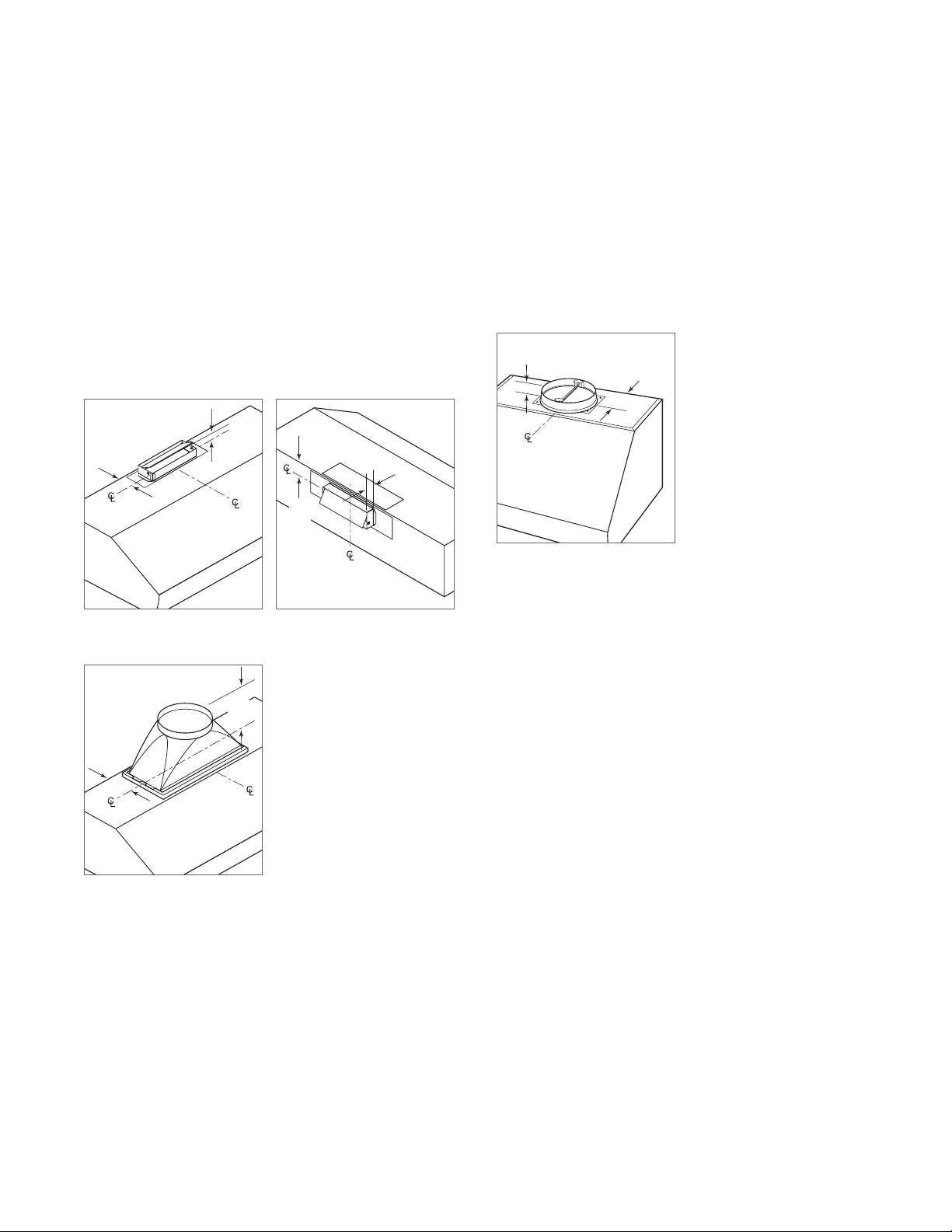
SPECIFICATIONS
Discharge
LOW-PROFILE WALL HOOD
Pro Low-Prole Wall Hoods with an internal blower can have
a vertical or horizontal discharge. Refer to the illustrations
below.
For Pro Low-Prole Wall Hoods with an in-line or remote
blower, a transition is required.
25/8"
(60)
Vertical discharge
11/2"
(38)
2"
(51)
Horizontal discharge
11/2" (38)
24"/27" DEEP WALL HOOD
Pro Wall Hoods that are 24" (610) and 27" (686) deep have a
vertical discharge. Refer to the illustration below.
2" (54)
Vertical discharge
55/8" (143)
TO CENTER
OF TRANSITION
55/8"
(143)
Accessory round transition
9"
(229)
wolfappliance.com | 7

SPECIFICATIONS
Electrical Requirements
Installation must comply with all applicable electrical codes.
Locate the electrical supply as shown in the illustration
below. A separate circuit servicing only this appliance is
required.
ELECTRICAL REQUIREMENTS
Electrical Supply grounded, 120 VAC, 60 Hz
Service 15 amp dedicated circuit
6"
E
(152)
5"
(127)
30" (762) TO 36" (914) BOTTOM EDGE TO COUNTERTOP
Hood Preparation
Remove the lters prior to installation. To remove, press
the lter upward and rotate the bottom. Remove the grease
cups from the bottom edge of the hood. Refer to the illustration below.
FILTER
GREASE
Filters
CUP
SPRING
SIDE VIEW
Electrical location
RATING PLATE
Rating plate location
8 | Wolf Customer Care 800.222.7820

INSTALLATION
Low-Prole Wall Hood
INSTALLATION
WARNING
Wall framing must be able to support the weight of the
hood and internal blower, if applicable.
1 Refer to the illustration for typical wall framing. Additional
framing or blocking is required in the mounting bracket
location.
2 Position the mounting brackets on the wall as shown
in the illustration below. Secure the brackets to the wall
framing and blocking with the provided screws and
washers.
261/4" (667)
MOUNTING BRACKET
CENTERS
71/4" (189)
TO BOTTOM
OF HOOD
BLOCKING
3 Install the transition. For an internal blower, the transi-
tion is included with the blower. For in-line and remote
blowers, a transition is required (not provided). Refer to
the illustration below.
4 Place the hood on the mounting brackets. Secure with
the provided screws through the mounting holes on the
back panel. Verify the screws engage the wall framing or
blocking. If additional support is required, drill supplementary holes through the back panel and secure with
screws and washers.
5 Insert Romex
®
wire(s) into the electrical box knockout
and secure with a UL or C/UL approved connector (not
provided).
6 Connect the ducting to the transition and secure with
duct sealing tape.
TRANSITION
Mounting bracket location
C
L
Transition (internal blower)
ELECTRICAL
BOX
(INSIDE HOOD)
Electrical box location
wolfappliance.com | 9

INSTALLATION
24"/27" Deep Wall Hood
INSTALLATION
WARNING
Wall framing must be able to support the weight of the
hood and internal blower, if applicable.
1 Refer to the illustration for typical wall framing. Additional
framing or blocking is required in the mounting bracket
location.
2 A wood mounting strip and hardware are provided with
the hood. Secure the mounting strip to the wall framing
and blocking with the provided screws and washers.
3 Position the mounting brackets on the mounting strip
as shown in the illustration below. Secure the brackets
to the mounting strip with the provided screws and
washers.
MOUNTING BRACKET LOCATION
30" (762) Hood 231/2" (597)
36" (914) Hood 241/2" (622)
42" (1067) Hood 301/2" (775)
48" (1219) Hood 361/2" (927)
54" (1372) Hood 421/2" (1080)
60" (1524) Hood 481/2" (1232)
66" (1675) Hood 541/2" (1384)
A
MOUNTING
STRIP
1
/2" (13)
151/8" (384)
TO BOTTOM
OF HOOD
MOUNTING BRACKET CENTERS
BLOCKING
A
Mounting bracket location
C
L
10 | Wolf Customer Care 800.222.7820

INSTALLATION
24"/27" Deep Wall Hood
INSTALLATION
4 The hood is shipped with the transition attached upside
down inside the top of the hood. Refer to the illustration
below.
5 Separate the transition from the hood by removing the
hold-down brackets. Remove the shipping material from
the transition.
6 Mount the transition and hold-down brackets to the top
of the hood using the existing screws. Refer to the illustration below.
7 For internal blowers, install the blower prior to mounting
the hood. Refer to the instructions provided with the
blower.
TRANSITION
HOLD-DOWN
BRACKET
8 Place the hood on the mounting brackets. Secure with
the provided screws through the mounting holes on the
back panel. If additional support is required, drill supplementary holes through the back panel and secure with
screws and washers.
9 Insert Romex
®
wire(s) into the electrical box knockout
and secure with a UL or C/UL approved connector (not
provided).
10 Connect the ducting to the transition and secure with
duct sealing tape.
MOUNTING STRIP
ELECTRICAL
BOX
(INSIDE HOOD)
TRANSITION
Transition position (shipping) Transition mounting
Hood installation
Electrical box location
wolfappliance.com
wolfappliance.com | 11
|
11

INSTALLATION
Electrical Connections
WARNING
Before making electrical connections, verify power is
turned off at the service panel.
IMPORTANT NOTE: Refer to installation instructions pro-
vided with the blower assembly.
INTERNAL BLOWER
1 Remove the hood’s electrical box cover.
2 Connect black to black and white to white with the
provided connectors, and connect the green/bare wire
to the ground screw.
3 Place all wiring connections inside the electrical box.
Verify all wires are secure and not pinched, and reinstall
the cover.
4 Insert the blower power cord into the receptacle inside
the hood. Refer to the illustration below. Turn the power
on and check operation.
IN-LINE/REMOTE BLOWER
1 Remove the hood’s electrical box cover.
2 Connect the home supply. Connect black to black and
white to white with the provided connectors, and connect the green/bare wire to the ground screw.
3 Connect the blower supply to the power cord provided
with the blower. Connect black to black, white to white,
and the green/bare wire to the ground screw.
4 Place all wiring connections inside the electrical box.
Verify all wires are secure and not pinched, and reinstall
the cover.
5 Insert the blower power cord into the receptacle inside
the hood. Refer to the illustration below. Turn the power
on and check operation.
RECEPTACLE
RECEPTACLE
ELECTRICAL
BOX
Blower receptacle
12 | Wolf Customer Care 800.222.7820
ELECTRICAL
Blower receptacle
BOX

INSTALLATION
Complete the Installation
FILTERS
Install the grease cups at the bottom rear edge of the hood.
Orient the lters with the lines running vertically. To install,
place the top edge of the lter against the spring, press
upward and rotate the bottom. Refer to the illustration
below.
LIGHT BULBS
A suction-cup-style light bulb changer is provided with
the hood. To install, use the changer to push the bulb into
the receptacle and rotate counterclockwise one-quarter
turn. Refer to the illustration below.
(686) deep wall hoods, install the heat lamp bulbs
For 27"
(not included). Use R40, 250W bulbs.
FILTER
GREASE
CUP
SPRING
WOLF LOGO
To attach the Wolf logo, clean the mounting area with rubbing alcohol. Remove the paper backing, position the logo
parallel with the bottom of the hood, then press into place.
Filters
SIDE VIEW
LIGHT BULB
CHANGER
Light bulb installation
wolfappliance.com | 13

BLOWER SPECIFICATIONS
28
29
29
11
Blower Dimensions
IN-LINE BLOWERS
243/8"
(619)
3
/4"
(298)
181/2"
(470)
41/2"
(114)
211/2"
(546)
121/4"
(311)
18"
(457)
12"
(305)
22"
(559)
8"
(203)
24
(632)
18"
(457)
7
/8
"
600 CFM in-line blower
REMOTE BLOWERS
3
/4
20
"
24
(629)
(527)
3
/4
"
1
(718)
/4
15
(394)
"
10" (254)
DIAMETER
1
/2
"
14"
(356)
600/900 CFM remote blower
24
(622)
1
/2
3
4
(121)
1100 CFM in-line blower
18" (457)
10"
1
/2
"
(749)
14
"
/4
"
(375)
10" (254)
DIAMETER
3
/4
"
1
/8
10
"
(257)
22"
(559)
1200 CFM remote blower
(254)
29
(749)
7
(184)
1
/2
"
(749)
1
/2
"
1
/4
"
14
(375)
10" (254)
DIAMETER
3
/4
"
3
/8
10
"
(264)
1500 CFM remote blower
25"
(635)
21" (533)
10"
(254)
29
(749)
7
(184)
1
/2
"
1
/4
"
14 | Wolf Customer Care 800.222.7820

TROUBLESHOOTING
Troubleshooting
IMPORTANT NOTE: If the hood does not operate properly,
follow these troubleshooting steps:
• Verify electrical power is supplied to the hood.
• Verify proper wiring connections.
• If the hood does not operate properly, contact Wolf
Factory Certied Service. Do not attempt to repair the
hood. Wolf is not responsible for service required to
correct a faulty installation.
Sub-Zero, Sub-Zero & Design, Sub-Zero & Snowake Design, Dual Refrigeration, The Living Kitchen, Great American Kitchens The Fine Art of Kitchen Design, Wolf, Wolf &
Design, Wolf Gourmet, W & Design, red colored knobs, Cove, and Cove & Design are registered trademarks and service marks of Sub-Zero Group, Inc. and its subsidiaries.
All other trademarks are property of their respective owners in the United States and other countries.
wolfappliance.com | 15

WOLF APPLIANCE, INC. P.O. BOX 44848 MADISON, WI 53744 WOLFAPPLIANCE.COM 800.222.7820
10/2018
 Loading...