


Installation instructions for contractors
Gas condensing boilers
MGK-2-390
MGK-2-470
MGK-2-550
MGK-2-630
Wolf GmbH • Postfach 1380 • D -84048 Mainburg • Tel. +49 (0)8751/74-0 • Fax +49 (0)8751/74-1600 • Internet: www.wolf-heiztechnik.de
Document no.: 3063772_201507 Subjecttotechnicalmodications
GB
(dt.)

2 3063772_201507
Table of contents
1. Information about this document ......................................................................... 3
2. Safety instructions .......................................................................................... 4 - 5
3. Dimensions ......................................................................................................... 6
4. Specification ........................................................................................................ 8
5. Boiler layout ........................................................................................................ 9
6. Casing ............................................................................................................... 10
7. Standards and regulations ......................................................................... 11 - 12
Installation
8. Handling / Installation instructions ..................................................... 13 - 15
9. Safety equipment...................................................................................... 16
10. Information about water treatment............................................................ 17
11. Boiler system pipework............................................................................. 18
12. Selection of circulation pumps .................................................................. 19
13. Gas connection......................................................................................... 20
14. Fitting the siphons .................................................................................... 21
15. Neutralising system (accessory)............................................................... 22
16. Neutralising system / Condensate pump (accessories) ........................... 23
17. Air/flue gas routing.............................................................................24 - 25
Control unit
18. Electrical connection..........................................................................26 - 31
19. Display/programming module / Installation............................................... 32
20. AM display module ................................................................................... 32
21. AM display module menu structure .......................................................... 34
22. Operating mode / Heating appliance burner status .................................. 35
23. BM2 programming module ....................................................................... 36
24. HG control parameters ............................................................................. 37
25. Parameter description .......................................................................38 - 47
26. Flue gas damper power supply ................................................................ 48
Cascade operation
27. Cascade operation ............................................................................49 - 51
Commissioning
28. Filling / draining the heating system ......................................................... 52
29. Commissioning ......................................................................................... 53
30. Checking the gas supply pressure ........................................................... 54
31. Changing the gas type / CO
2
settings ................................................55 - 56
Specification
32. Commissioning report............................................................................... 57
33. Design information – air/flue gas routing .................................................. 58
34. Wiring diagram HCM2 /GBC-P ..........................................................59 - 60
35. Troubleshooting .................................................................................61 - 64
36. Troubleshooting warning messages ......................................................... 65
37. Sensor resistance table ............................................................................ 66
38. Technical parameters according to EU regulation no. 813/2013 .............. 67
Declaration of conformity .................................................................................. 68

3063772_201507 3
1. Information about this document
1.1 Other applicable documents
MGK-2 user operating instructions
MGK-2 maintenance instructions
System and operator's log
The instructions for all accessory modules and other accessories may also apply.
1.2 Safekeeping of these documents
The system user or operator should ensure the safekeeping of all instruction manuals
and documents.
f Please pass these installation instructions and all other applicable instruction
manuals on to the operator and/or system user.
1.3 Obligations of the operator
System operators must take active steps to full their responsibilities regarding safe
gas use. This applies to the commissioning of specialist companies to maintain the
appliance. The system operator is obliged to provide documentation.
1.4 Applicability of these instructions
These installation instructions apply to the MGK-2 gas condensing boiler
1.5 Acceptance
Within four weeks of commissioning of the burner the operator must notify the local
ue gas inspector accordingly.
1.6 Information about disposal
We are happy to accept the return of your old Wolf boiler free of charge at one of our
delivery depots.
1 x MGK-2 gas condensing boiler, fully encased, assembled and wired
2 x siphons with 3 condensate hoses and 1 tee
1 x condensate trap
1 x MGK-2 installation instructions for contractors
1 x MGK-2 user operating instructions
1 x MGK-2 maintenance instructions
1 x system and operator's log
MGK-2 standard delivery
4 3063772_201507
2. Safety instructions
The following symbols are used in these instructions. This
important information concerns personal as well as
operational safety.
"Safety instructions" are instructions with
which you must comply exactly, to prevent risks
and injuries to individuals and damage to the
boiler.
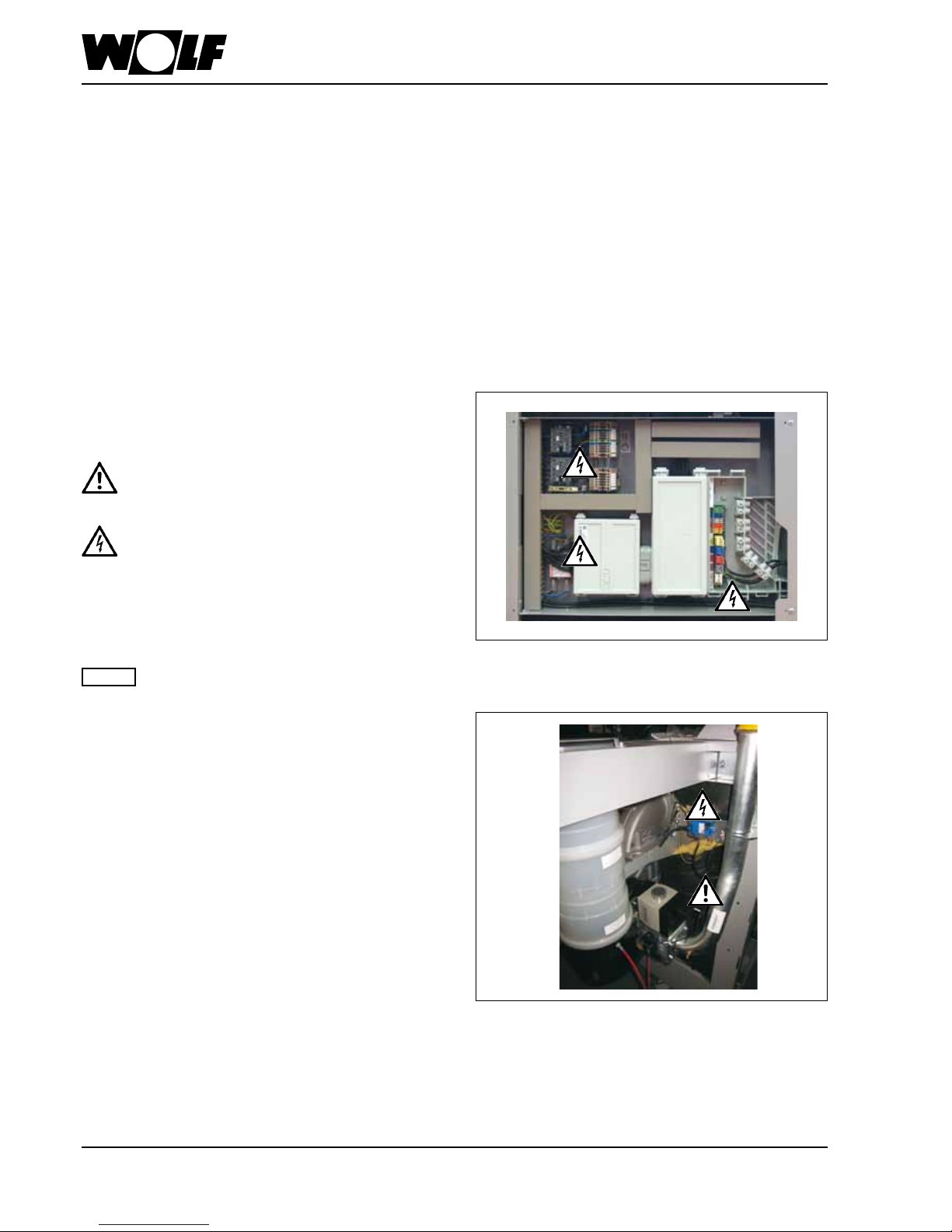
Danger due to live electrical components.
Please note: Turn OFF the ON/OFF switch before
removing the casing.
Never touch electrical components or contacts
when the ON/OFF switch is in the ON position.
This can result in a risk of electrocution that
could lead to injury or death.
The terminals are live even when the ON/OFF
switch is in the OFF position.
"Caution" indicates technical instructions that
you must observe to prevent boiler damage and
malfunctions.
Caution
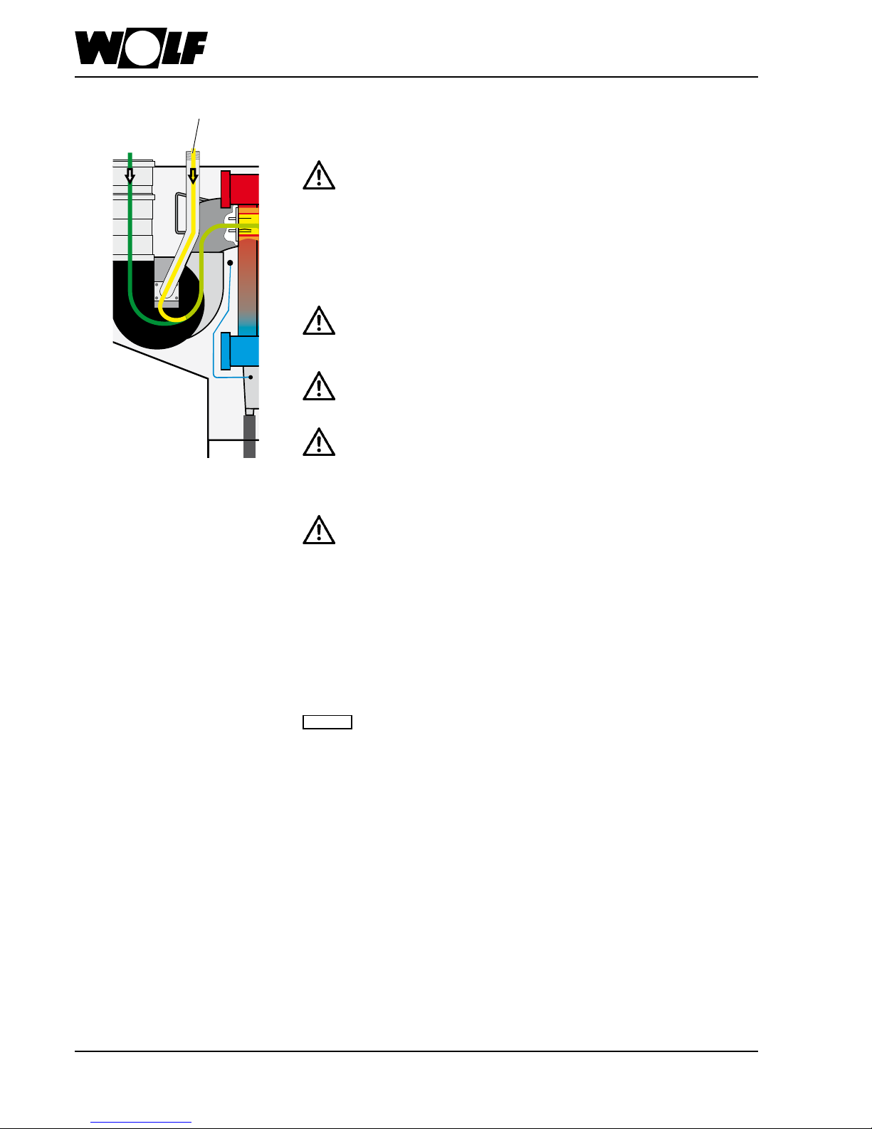
Fig: Ignition transformer, high voltage ignition electrode, gas
combination valve, gas pressure switch, fan, combustion
chamber.
Danger from electrical voltage, escaping gas may cause
poisoning or an explosion, risk of burning through hot
components.
Danger if you smell gas
- Close the gas shut-off valve.
- Open the windows.
- Do not operate electrical switches.
- Extinguish naked flames.
- Phone the gas supply utility company and approved
contractor from an external location.
Authorised personnel should read these instructions before any installation, commissioning or maintenance work. Observe
the instructions given in this document. Failure to observe these installation instructions voids any WOLF warranty. In
some countries, the installation of a gas boiler must be notified to and approved by the relevant gas supply company.
Please note that regional permits may be required for the flue system and the condensate drain into the public sewer.
Before installation work begins, the local flue gas inspector and water authority must be informed. The boiler must be
installed, commissioned and maintained by qualified and trained personnel only. In accordance with VDE 0105 Part 1,
work on electrical components (e.g. control unit) must only be carried out by qualified electricians. VDE/ÖVE regulations
and those of your local power supply utility company are applicable to electrical installation work. Only operate the boiler
within its output range, which is stated in the technical documentation supplied by WOLF. Intended use of the boiler refers
to the exclusive use for hot water heating systems in accordance with DIN EN 12828. Never remove, bypass or otherwise
disable any safety and monitoring equipment. The boiler must only be operated if it is in perfect technical condition. Any
faults and damage with potential impact on safety and which might limit the safe use of the equipment must be remedied
immediately by a qualified contractor. Only replace faulty components and equipment with original WOLF spare parts.
Working on the system
- Gas systems: close the gas shut-off valve and ensure that
unauthorised reopening is prevented.
- Isolate the system from the power supply (e.g. by removing
a separate mains fuse or by means of a mains electrical
isolator, heating emergency stop switch) and check to
ensure that there is no voltage.
- Safeguard the system against restarting.
Fig: Control box
Danger from electrical voltage
3063772_201507 5
2. Safety instructions
Danger if you smell flue gas
- Switch OFF the boiler.
- Open windows and doors.
- Notify an approved contractor.
Inspection and maintenance
- Recommendation for the customer: Take out an inspection
and maintenance contract with an approved contractor,
including an annual inspection and demand-dependent
servicing.
- The operator is responsible for the safety, environmental
compatibility and energy quality of the heating system
(German Immission Control Act / Energy Saving Ordinance).
- Only use genuine spare parts!
This appliance is not designed to be operated by persons
(including children) with restricted physical, sensory or
mental capacities or who lack the necessary experience
and/or knowledge, unless they are supervised by a person
responsible for their safety or have received instructions
on how to use the appliance from this person.
We accept no liability for damage caused by
technical modifications made to the control unit
or the control system components.
These installation instructions must be kept in
a safe place and read before installing the boiler.
Please also observe the design information in
the appendix.
Note
Information about disposal:
We are happy to accept the return of your old Wolf boiler free
of charge at one of our delivery depots.
6 3063772_201507
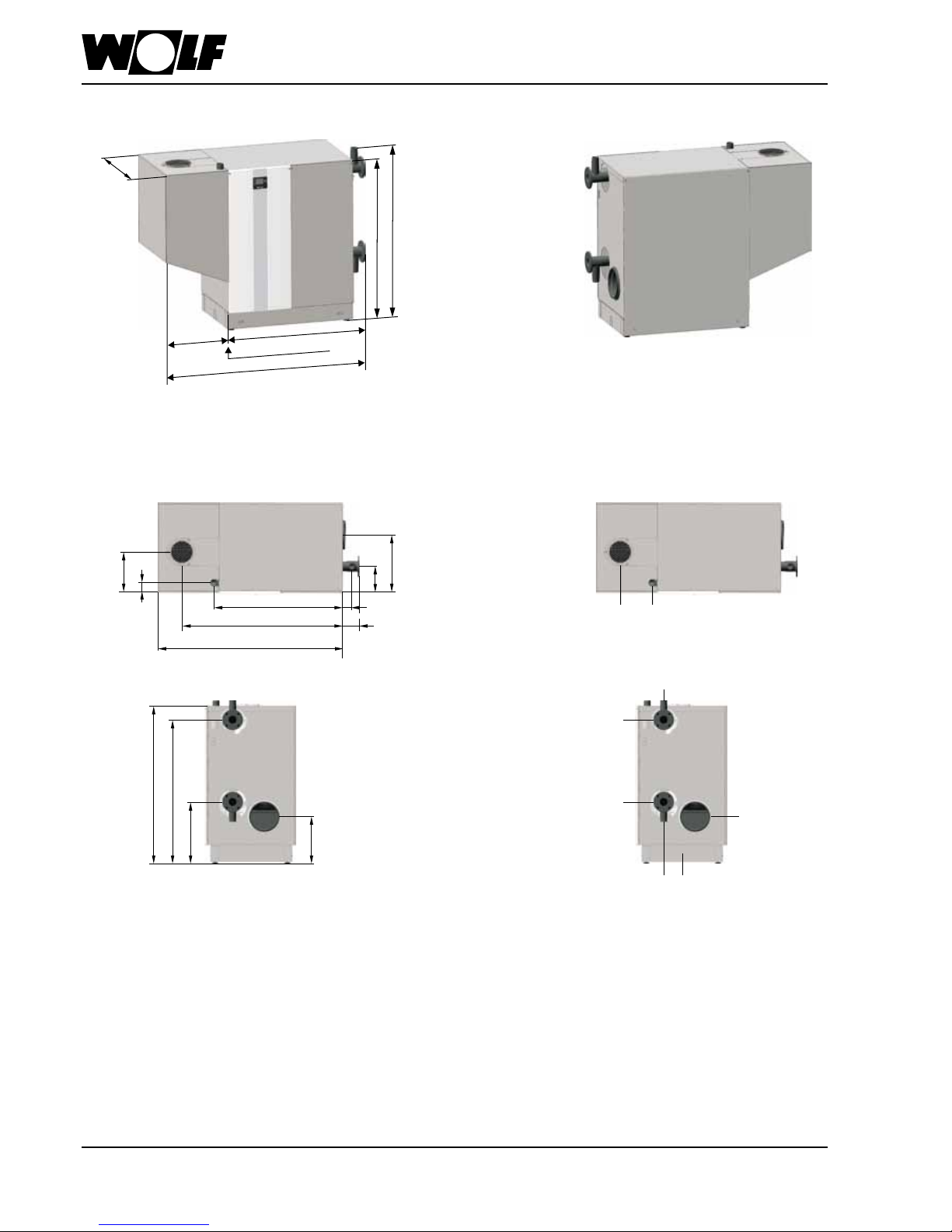
3. Dimensions
A = ventilation air pipe DN 200
B = gas pipe 2"
C = safety assembly connection 2"
D = flow pipe DN 80
E = return pipe DN 80
F = BDF valve connection
G = flue pipe DN 250
H = condensate drain
850
(790 without
casing)
Can be split for transportation
1295
1860
565
1460
1420
365
240
525
1290
1420
535
410
160
1180
1480
1700
85
85
C
D
E
G
F H
A B
3063772_201507 7
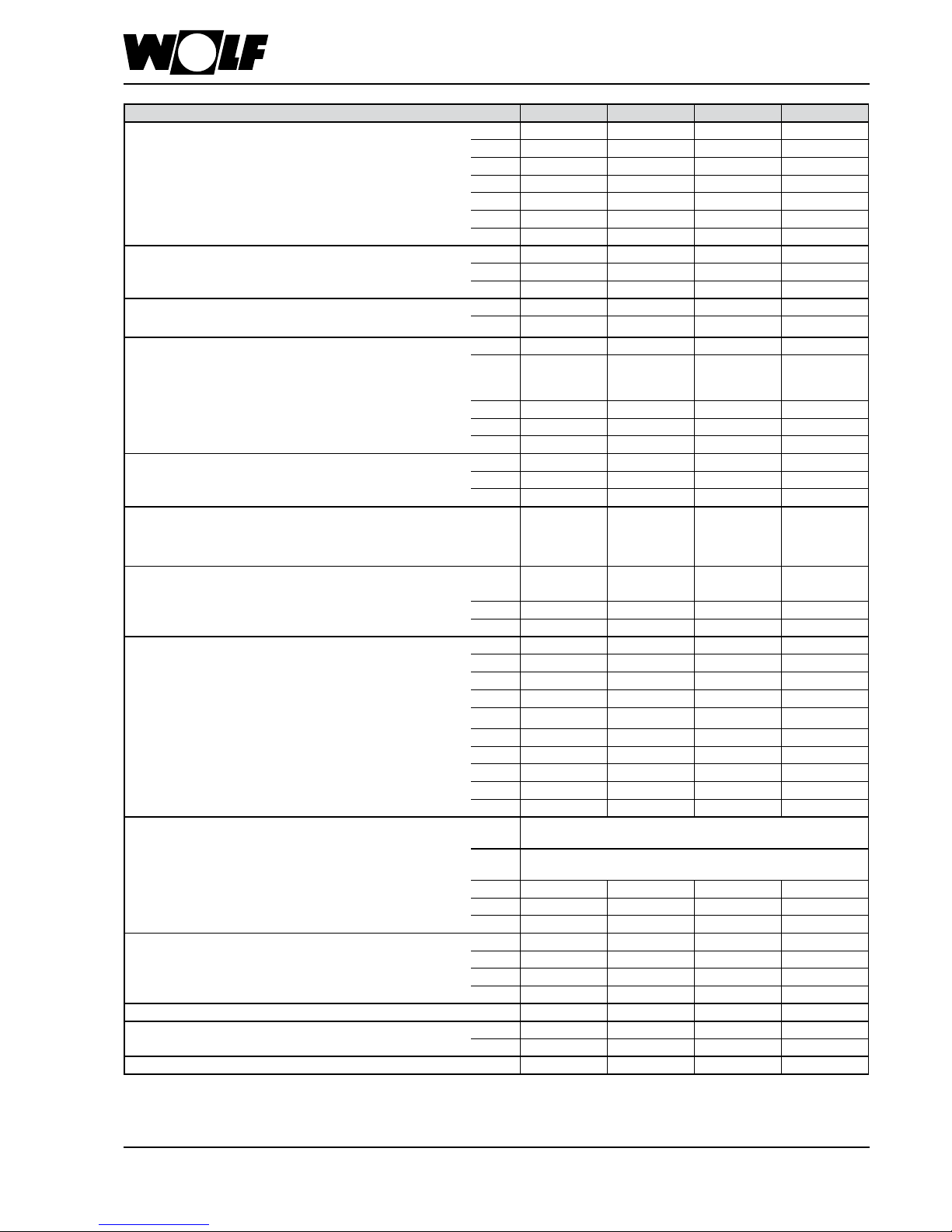
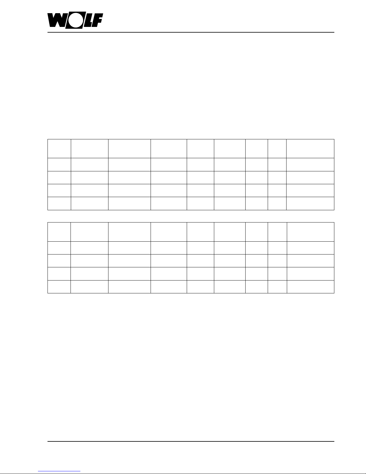
4. Specication
Type MGK-2 390 470 550 630
Rated heating output at 80/60 °C kW 366.7 434.7 511.6 584.4
Rated heating output at 50/30 °C kW 392.0 467.1 549.3 626.6
Rated heat input kW 371.2 443.6 521.0 593.9
Low boiler output (modul.) at 80/60 °C kW 58.5 70.7 84.5 96.7
Low boiler output (modul.) at 50/30 °C kW 64.2 78.7 94.0 106.8
Low heat input (modulating) kW 59.5 73.2 86.8 98.5
Heat input modulation range % 17-100 17-100 17-100 17-100
Efciency η 80/60 at Qmax % 98.8 98.0 98.2 98.4
η 50/30 at Qmax % 105.6 105.3 105.4 105.5
η TR30 at 30 % % 107.8 108.9 108.6 107.6
Standard seasonal efciency at 40/30 °C % 109.9 110.1 110.3 110.4
at 75/60 °C
% 106.4 106.4 106.3 106.3
Overall height mm 1460 1460 1460 1460
Overall width mm
1860
(1295 in
sections)
1860
(1295 in
sections)
1860
(1295 in
sections)
1860
(1295 in
sections)
Overall depth / depth without casing mm 850 / 790 850 / 790 850 / 790 850 / 790
Flue diameter mm 250 250 250 250
Combustion air supply mm 200 200 200 200
Heating ow DN 80 PN6 80 PN6 80 PN6 80 PN6
Heating return DN 80 PN6 80 PN6 80 PN6 80 PN6
Gas connection R 2" 2" 2" 2"
Air/ue gas routing Type B23, B23P,
C33, C43,
C53, C63,
C83, C93
B23, B23P,
C33, C43,
C53, C63,
C83, C93
B23, B23P,
C33, C43,
C53, C63,
C83, C93
B23, B23P,
C33, C43,
C53, C63,
C83, C93
Gas supply details:
Natural gas E/H (H
i
= 9.5 kWh/m³ = 34.2 MJ/m³) m³/h 39.1 46.7 54.8 62.5
Natural gas LL (H
i
= 8.6 kWh/m³ = 31.0 MJ/m³) m³/h 43.2 51.6 60.6 69.1
Gas supply pressure: Natural gas E/H/LL mbar 20 20 20 20
Water content, heating water heat exchanger l 50 56 62 68
Max. permissible boiler pressure bar 6 6 6 6
Max. permissible ow temperature °C 85 85 85 85
Available gas fan draught Pa 150 150 150 150
Standby losses excess temperature
30 / 50 K
% 0.11 / 0.18 0.10 / 0.17 0.09 / 0.15 0.09 / 0.14
Flue gas temperature 80/60-50/30 at Qmax °C 65-35 65-35 65-35 65-35
Flue gas temperature 80/60-50/30 at Qmin °C 60-30 60-30 60-30 60-30
Max. ue gas volume ow
g/s 156.3 185.2 225.3 247.4
Flue gas category to DVGW G 635 G 52 G 52 G 52 G 52
Heating water pressure drop at 20 K spread mbar 120 113 126 118
Electrical connection of MCB protection V~/Hz
1~ NPE / 230 V AC / 50 Hz / 10 A/B
Alternative: 3~ PE / 400 V AC / 50 Hz / 10 A/B
Output heating circuit pump / ZHP fuse/MCB protection V~/Hz
1~ NPE / 230VAC / 50Hz / 4A
Alternative: 3~ PE / 400 V AC / 50 Hz / 4 A
Power consumption (partial load / full load) W 42 - 410 45 - 490 48 - 580 50 - 660
Standby power consumption W 11 11 11 11
IP rating IP20 IP20 IP20 IP20
Sound power to DIN EN 15036 Part 1, balanced ue dB(A) 61 66 68 68
Sound pressure level 1 m upstream of MGK-2, balanced ue
1)
dB(A) 44 49 50 50
Sound power to DIN EN 15036 Part 1, open ue dB(A) 78 82 84 84
Sound pressure level 1 m upstream of MGK-2, open ue
1)
dB(A) 60 64 65 65
Total weight (dry) kg 390 420 450 480
Amount of condensate at 40/30 °C l/h 39 46 52 59
Condensate pH value approx. 4.0 approx. 4.0 approx. 4.0 approx. 4.0
CE ID 0085CN0326 0085CN0326 0085CN0326 0085CN0326
1)
depending on the general system conditions, such as: type/version of the flue system, size and nature of the installation room

8 3063772_201507
4. Specication
Max. spread A cast section protection function is integrated in the MGK-2. This prevents stresses in
the material by limiting the maximum temperature differential between the flow and
return. As of 28 K, the output is reduced. If 40 K is nevertheless reached, the burner
shuts down briefly without a fault message. This characteristic must be taken into account
when selecting the components (e.g. pumps, heat exchanger and cylinder).
Flow rate Excessive flow velocities may lead to erosion.
Maximum flow rate (volume flow) at Q
max
:
MGK-2-390: 28.5 m³/h
MGK-2-470: 34.4 m³/h
MGK-2-550: 39.8 m³/h
MGK-2-630: 45.5 m³/h
MGK-2 heating water pressure drop:
Heating water pressure drop [mbar]
Throughput [m³/h]
MGK-2-550
MGK-2-630
MGK-2-470
MGK-2-390
3063772_201507 9
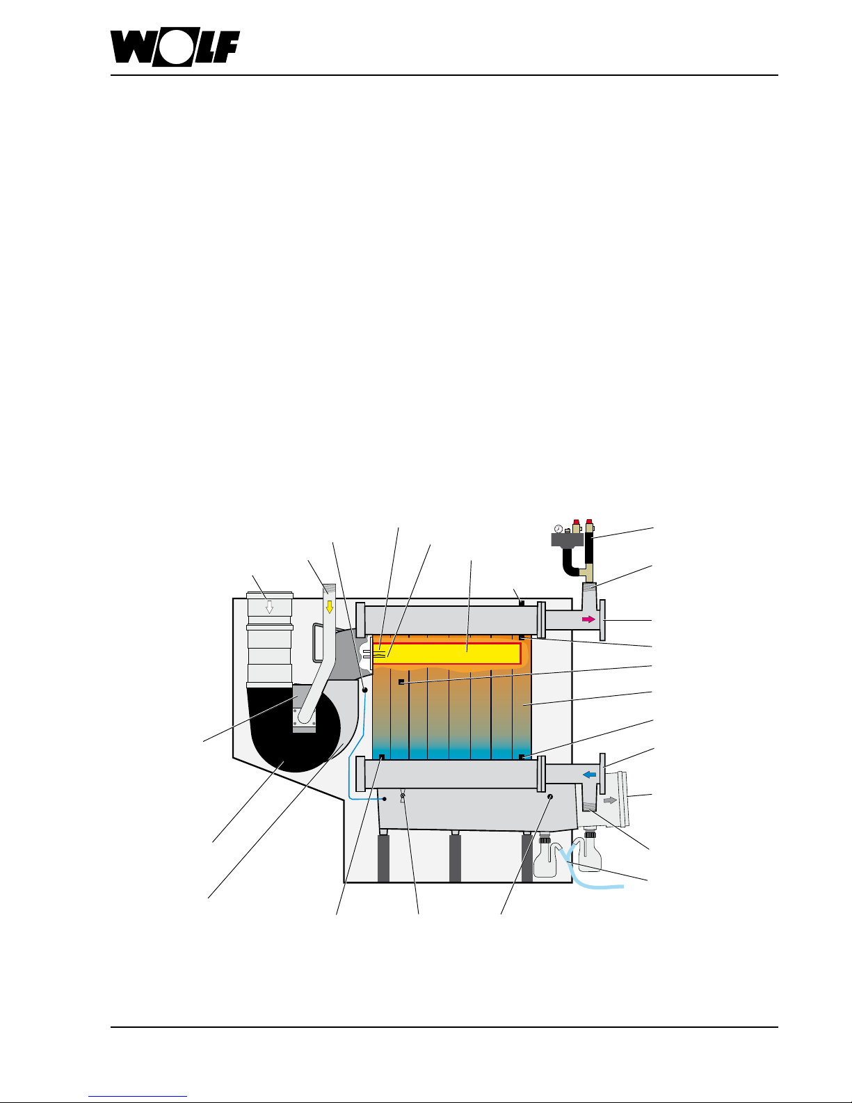
5. Boiler layout
Wolf MGK-2-390/470/550/630 gas condensing boilers are adjusted at the factory for
natural gas E and LL. The high performance heat exchanger is made from robust
aluminium-silicon alloy with a high resistance to corrosion. The gas premix burner with
gas-air mixture for modulating combustion from 17-100 % ensures extremely clean
combustion with a standard seasonal efficiency [to DIN] of up to 110 % for highly efficient
energy utilisation. The connections for the combustion air supply – for room sealed
operation – and gas are on the top of the boiler. The flue gas, heating flow and heating
return connections are on the side of the boiler. The removable burner hood guarantees
easy access for servicing the gas-air mixing unit.
Compact, space-saving installation right up against the wall with no clearance needed.
Quick and easy installation thanks to pre-installed thermal insulation and casing,
hydraulically and electrically ready to connect.
Direct access to all components from the front, simple operation and maintenance.
Integral attenuation minimises sound emissions, ideal for apartment buildings.
• Control unit fully wired; may be used for a wide range of heating system applications
• Cascades with up to four gas condensing boilers provide an output range of up to
2.5 MW
• No return temperature raising facility or minimum water circulation volume required
• Additional 2nd HLSC already integrated in the device
The boiler is fully assembled and encased.
The standard control unit includes a burner control unit, electronic ignition, ionisation
flame monitor and output-dependent fan speed regulation.
Flue gas pressure
switch
Ignition electrode
Monitoring electrode
Round gauze burner
Additional
HLSC
Safety assembly 2"
(accessory)
Gas combination
valve with gas
pressure limiter
Flue gas temperature sensorBDF valveWater pressure sensor
Gas fan
Mixing chamber
Ventilation air
pipe DN200
Gas connection R2"
Flue outlet DN250
Connection R2" for
safety assembly
Heat exchanger as a
sectional design
Connection R2" for
BDF set (accessory)
Siphons with
condensate drain
Flow connection
DN80 / PN6
Boiler water temperature sensor
Return temperature
sensor
Return connection
DN80 / PN6
Temperature sensors
eHLSC1 and eHLSC2
Layout MGK-2
10 3063772_201507
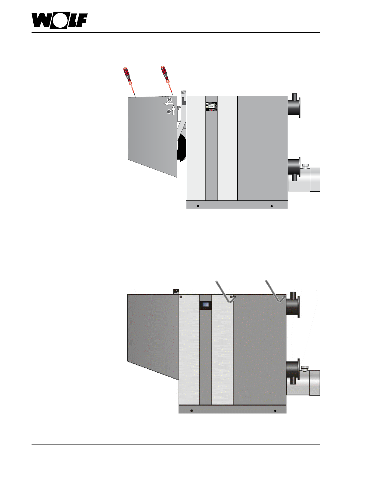
6. Casing
- Remove 3 screws on the top of the boiler.
- Lift burner hood slightly and remove from boiler.
- Remove 2 screws on the right side casing of the boiler.
- Tip right side casing forward and lift off.
Re-assemble in reverse order.
Re-assemble in reverse order.
Remove burner hood
(e.g. for servicing the gas-air mixing unit)
Open side casing
(e.g. to connect boiler to power
supply):

3063772_201507 11
7. Standards and regulations
Observe all standards and guidelines applicable to the installation and
operation of this heating system in your country.
Observe the information on the boiler type plate.
The following local regulations must be complied with for installation and
operation:
• Regulations on installation conditions
• Regulations on the ventilation air and exhaust air and the connection to a chimney
• Electrical connection to the power supply
• The technical regulations of the gas supply utility company regarding the
connection of the gas appliance to the local gas mains
• The regulations and standards regarding the safety equipment of the water
heating system
• DHW installation
The following general regulations, rules and guidelines must be observed for
installation in particular:
• (DIN) EN 1717 Protection of DHW against contamination in DHW installations
• (DIN) EN 12831 Heating systems in buildings – procedure for calculating the
standard heat load
• (DIN) EN 12828 Heating systems in buildings – designing hot water heating
systems
• (DIN) EN 13384 Flue systems – heat and flow rate calculations
• (DIN) EN 50156-1 (VDE 0116 Part 1) Electrical equipment in combustion systems
• VDE 0470/(DIN) EN 60529 Protection through casings
• VDI 2035 Prevention of damage in hot water heating systems
- Scaling (sheet 1)
- Corrosion in the primary system (sheet 2)
- Corrosion in the flue system (sheet 3)
The following also apply to installation and operation in Germany:
• Technical Regulations for Gas Installations DVGW-TRGI 1986/1996 (DVGW Code
of Practice G600 and TRF)
• DIN 1988 Technical regulations for DHW installations
• DIN 18160 Flue systems
• DWA-A 251 Condensate from condensing boilers
• ATV-DVWK-M115-3 Indirect discharge of non-domestic waste water
Part 3: Indirect discharge practice
• VDE 0100 Regulations regarding the installation of high voltage systems with
rated voltages up to 1000 V
• VDE 0105 Operation of high voltage systems, general stipulations
• KÜO German Federal Sweeping and Inspection Act
• Energy Savings Act (EnEG) and related ordinances
• EnEV Energy Saving Ordinance (currently applicable version)
• DVGW Code of Practice G637

12 3063772_201507
7. Standards and regulations
For installation and operation in Austria, the following apply:
• ÖVE regulations
• Provisions of the ÖVGW and the corresponding Austrian standards
• ÖVGV TR-Gas (G1), ÖVGW-RTF (G2)
• Provisions of ÖVGW guideline G41 for condensate drainage
• Local regulations of building and industry regulatory agencies (usually represented
by the flue gas inspector)
• Local regulations of the gas supply utility company
• Regulations and requirements of the local power supply utility company
• Provisions of regionally applicable building regulations
• Minimum heating water requirements in accordance with ÖNORM H5195-1 must be
observed
For installation in Switzerland, the following apply:
• SVGW regulations
• VKF regulations
• BUWAL and local regulations must be observed
• G1 gas guidelines
• EKAS form 1942; LPG guideline Part 2
3063772_201507 13
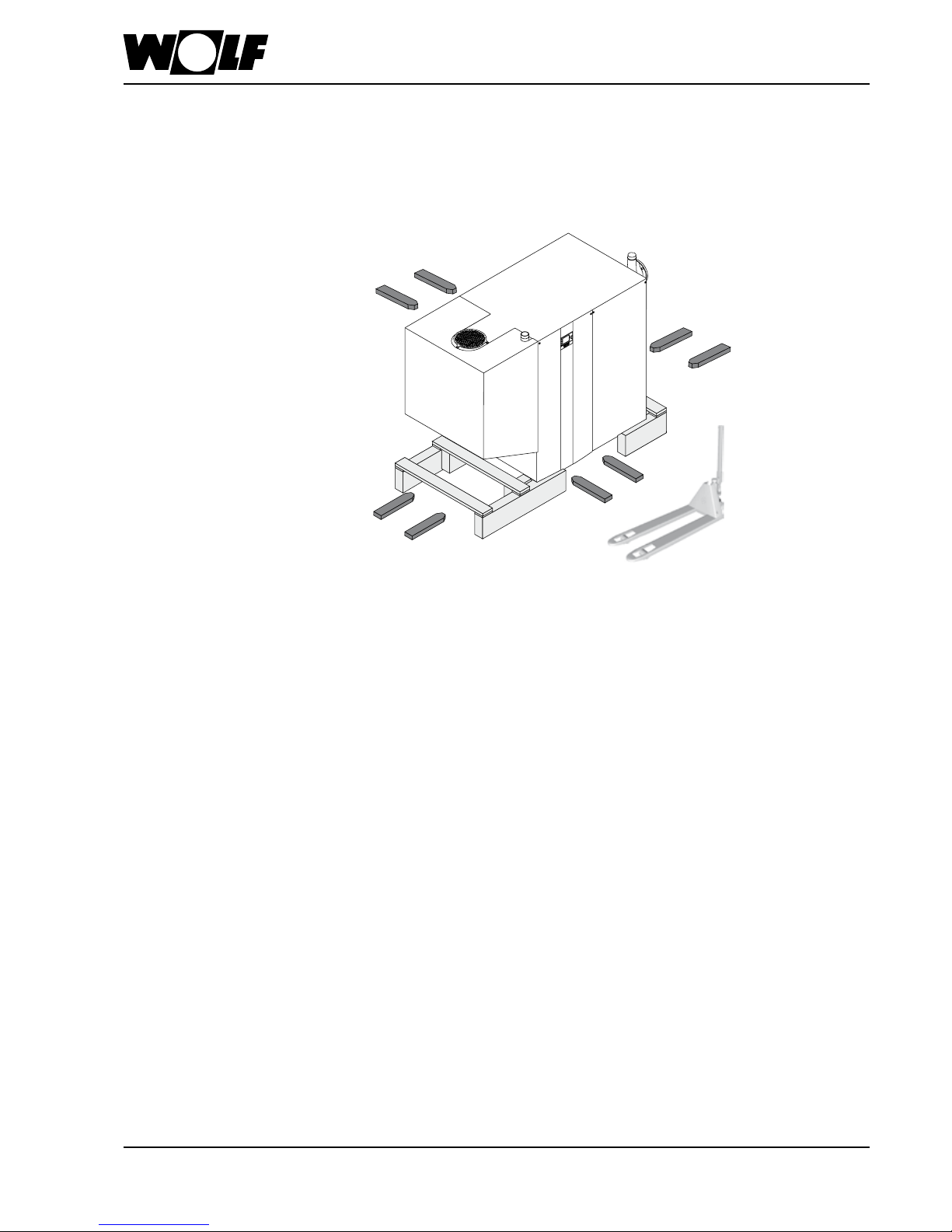
8. Handling / Installation instructions
Handling • With ground conveyor vehicle:
With or without a pallet, the boiler can be handled easily using a pallet truck or
forklift, as it can be lifted from any side.
Example:
14 3063772_201507
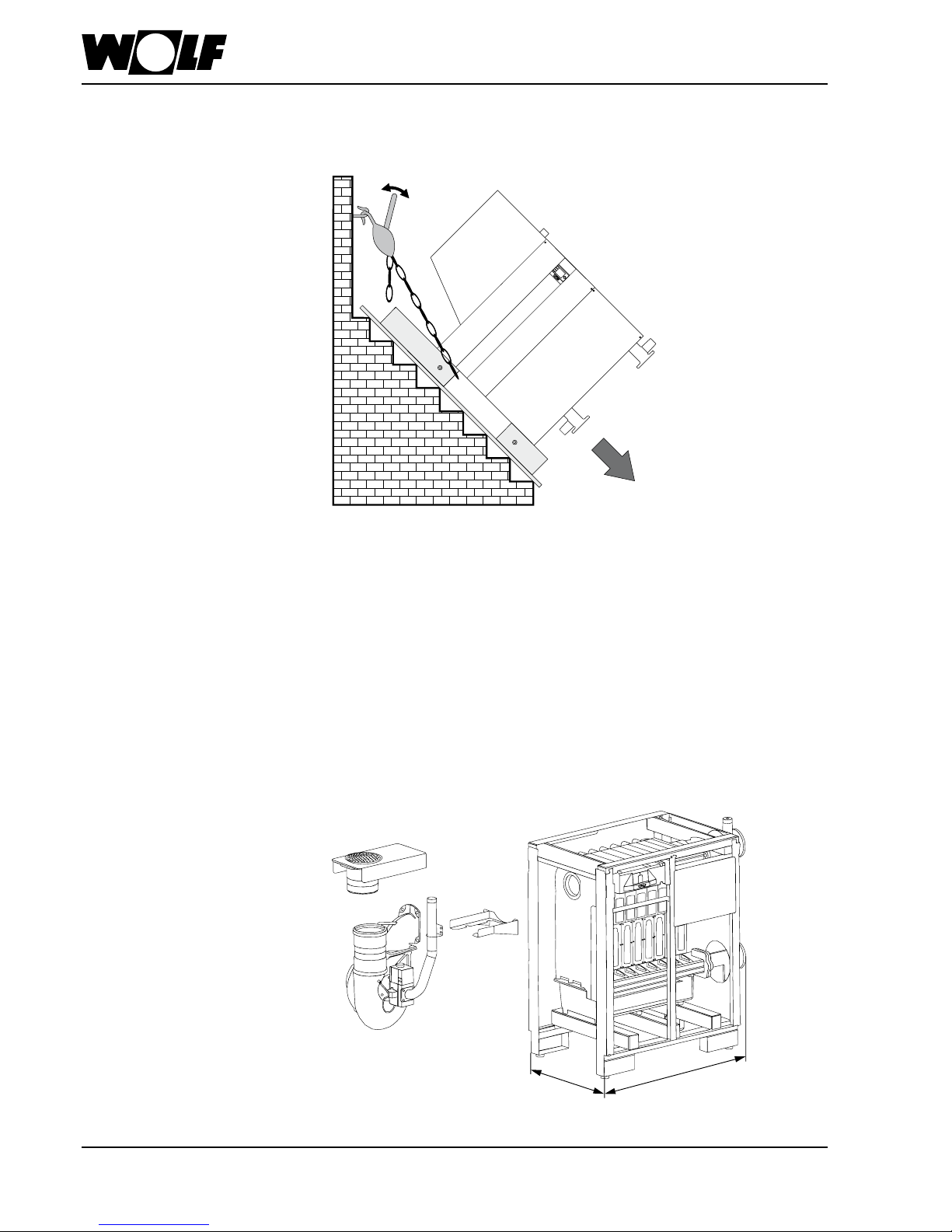
8. Handling / Installation instructions
Dimensions after separating:
• Can be lowered into the basement with a cable winch or chain hoist, secured to
prevent it from sliding down on its own.
The gas condensing boiler can be separated into a gas-air mixing unit and heat
exchanger unit measuring 790 mm x 1295 mm for easier handling.
- Remove the burner hood
- Remove the gas-air mixing unit
- Remove the retainer for the gas-air mixing unit
Example:
1295 mm
790 mm
3063772_201507 15
• The boiler should be installed on a level surface which is substantial enough to carry
its weight.
• The boiler must be level (level with adjustable feet).
The boiler must only be installed in a room that is protected from frost.
If there is a risk of frost while the system is shut down, drain the boiler and
the system components that are at risk to prevent pipes from bursting.
Boilers should not be installed in areas subject to aggressive vapours, very
dusty or highly humid conditions (workshops, wash rooms, hobby rooms etc.).
This prevents the optimum burner function from being achieved.
The installation room and the combustion air supplied to the boiler must be
free from halogenated hydrocarbons (e.g. as contained in sprays, solvents,
cleaning uids, paints and adhesives). At worst these can lead to pitting of
the boiler and even the ue system.
Never store or use combustible material or liquids near the boiler.
The ventilation air supply must be ensured and must comply with local
regulations or those relating to gas installations. An insufcient fresh air supply
can lead to ue gas escaping, which represents a risk to life (poisoning/
suffocation).
A neutralising system for the condensate is a basic requirement and is
available as an accessory.
Caution
Caution
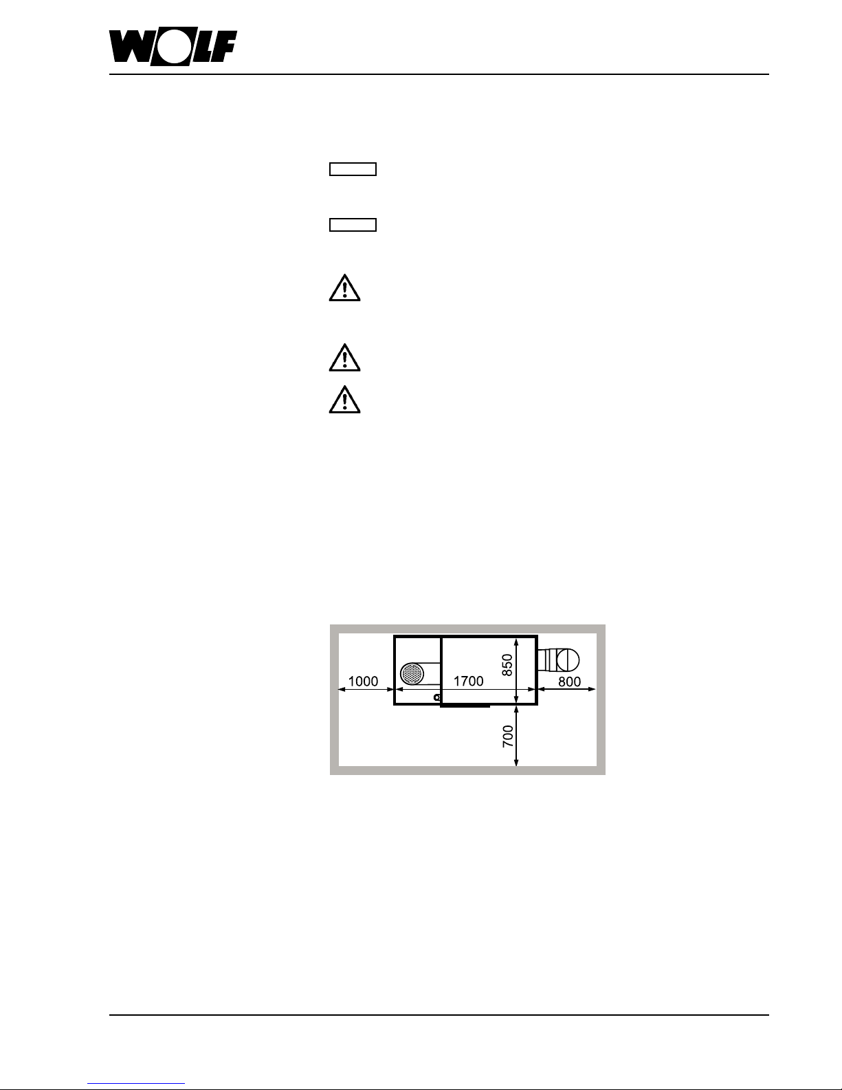
8. Installation instructions
Fig: Boiler in the installation room
Different minimum clearances must be observed when installing the boiler in the
installation room.
Minimum clearances:
Installation instructions
16 3063772_201507
9. Safety equipment
The safety equipment for central heating systems must comply with DIN EN 12828.
This standard applies to all hot water heating systems and heat generation systems
with a maximum operating temperature of 105 °C and a maximum output of 1 MW.
Note: Provide a drain and fill valve at the lowest system point.
The minimum system pressure is 0.8 bar. The gas condensing boilers are approved exclusively for sealed unvented systems up
to 6 bar (safety assembly accessories 3 bar). The maximum flow temperature is factory-set to 85 °C on the MGK-2 and may be
adjusted to 90 °C if required.
There is no need for a minimum throughput at maximum flow temperatures below 85 °C.
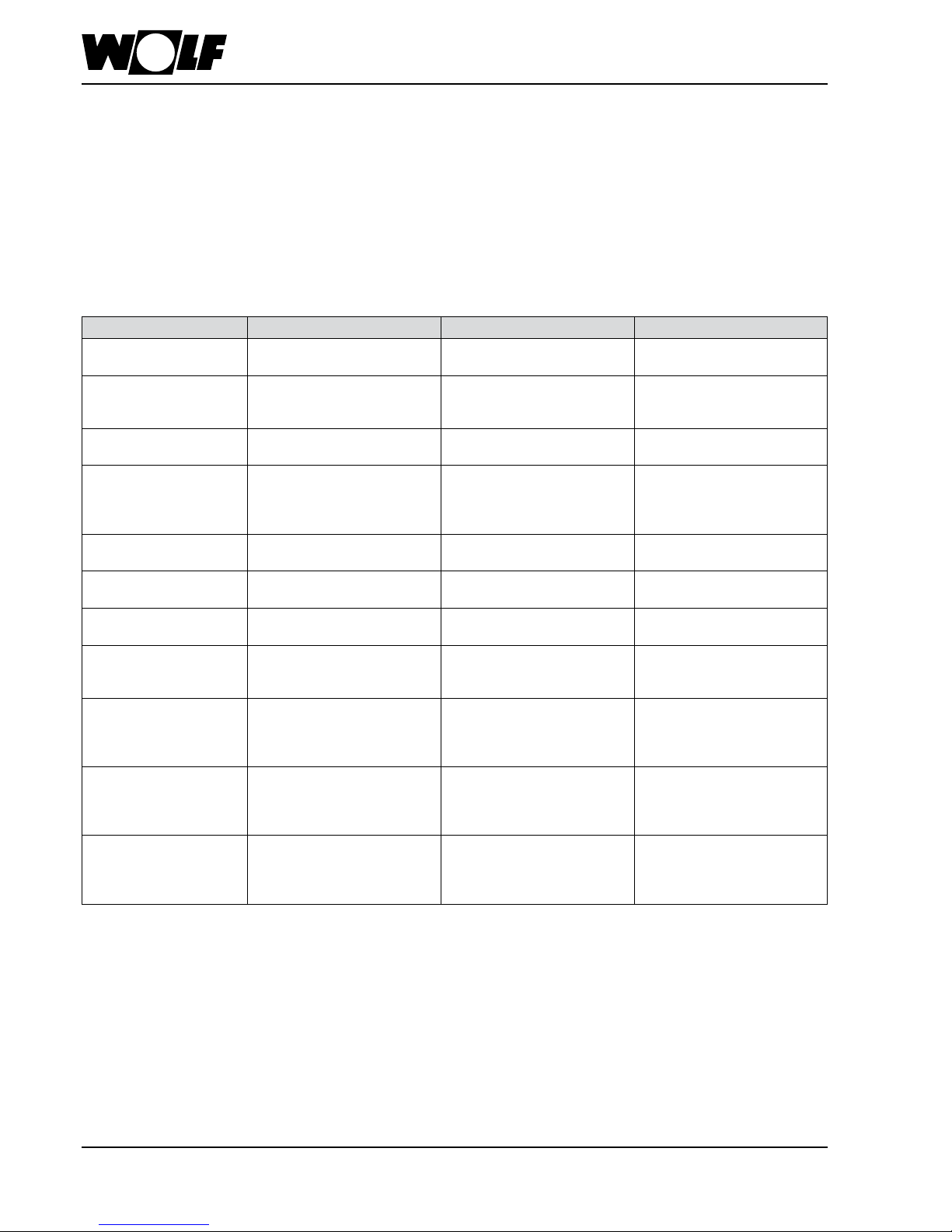
Equipment level to DIN EN 12828
for MGK-2
Task Function MGK-2 installation location Comments
Temperature indicator
(°C)
Display Integrated in boiler
High limit safety cut-out
(HLSC)
Device to prevent ow
temperature being exceeded
Integrated in the boiler,
2nd HLSC integrated in boiler
(eHLSC)
Second electronic high
limit safety cut-out already
integrated in boiler
Temperature controller Device to prevent ow
temperature being exceeded
Integrated in boiler and set to
85 °C
Max. setting 90 °C
Low water indicator Low water indicator Device to
prevent incorrect heating when
water level or volume ow are
insufcient
In ow line near MGK-2 Can be substituted by
minimum pressure limiter.
Flow limiter Functions like low water
indicator
Not required Replaced by
maximum pressure limiter
Water level limiter Functions like low water
indicator
Not required Replaced by
minimum pressure limiter
Pressure measuring
device (bar)
Display Integrated in boiler Integrated in safety assembly
as accessory
Safety valve Facility to prevent permissible
operating pressure being
exceeded
Flow line near heat source Integrated as accessory (up to
3 bar) in the safety assembly
Maximum pressure limiter Devices for preventing the
permissible operating pressure
being exceeded
In ow line near MGK-2
2nd maximum pressure limiter
that can be integrated in Wolf
safety assembly (accessory)
Two can be installed as
accessories in MGK-2 safety
assembly accessory
Flash trap Facility to prevent permissible
operating pressure being
exceeded
Near safety valve or replaced
by 2nd HLSC (already
integrated) and 2nd maximum
pressure limiter
Can be replaced by 2nd
maximum pressure limiter and
2nd high limit safety cut-out
Expansion vessel
diaphragm
Device to compensate
for changes in water
volume (external pressure
maintenance)
Return line Expansion vessels should be
able to be securely isolated
and emptied for maintenance
purposes
3063772_201507 17
10. Information about water treatment
The system must be cleaned / flushed thoroughly before
commissioning and a sludge filter/dirt trap
(e.g. Wolf accessory, <500 μm = 0.5 mm mesh width MW)
installed in the return line. This must be in close proximity to
the heating appliance and at the lowest position in the heating
system.
The fill and top-up water must only be treated with a
desalination process. The "Maximum permissible total
hardness" table shows the degree to which water treatment is
required.
The system water must not fall below a total hardness of 2°dH,
which corresponds to conductivity of ≈ 60 μS/cm. The max.
permissible total hardness and the corresponding max.
conductivity are system-specific and must be calculated (see
also "Maximum permissible total hardness" table). The
desalinated water (conductivity <= 30 μS/cm) must not be
mixed with untreated DHW.
The addition of chemicals or de-scaling using single-stage ion
exchangers is not permissible, as system damage due to water
leaks may occur.
We recommend regular emptying of the sludge filter.
The operator must ensure that the heating system is maintained
and serviced regularly to maintain its energy quality (see
EnEV).
The Wolf system and operator's log for treatment of
heating water must be kept in a safe place and made
available by the owner / operator. It is provided along with
these installation instructions.
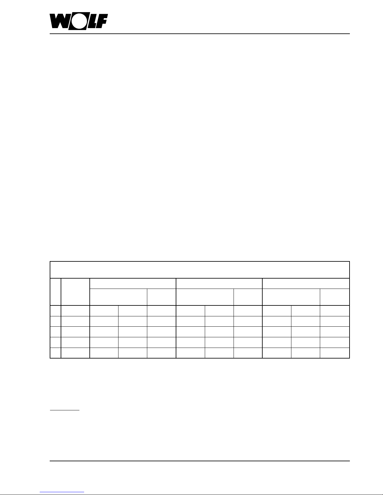
Limits depending on the spec. system volume VS (VS = system volume / lowest individual output)
Total hardness conversion: 1 mol/m³ = 5.6°dH
Total
heating
output
VS ≤ 10 l/kW VS > 10 l/kW and < 40 l/kW VS ≤ 40 l/kW
Total hardness / total
alkaline earths
Conductivity
Total hardness / total
alkaline earths
Conductivity
Total hardness / total
alkaline earths
Conductivity
[kW] [°dH] [mol/m³] C [μS/cm] [°dH] [mol/m³] C [μS/cm] [°dH] [mol/m³] C [μS/cm]
1* < 50 2 - 16.8* 0.36 - 3.0* 60 - 500 2 - 11.2 0.36 - 2.0 60 - 300 2 - 3 0.36 - 0.54 60 -100
2 50-200 2 - 11.2 0.36 - 2.0 60 - 300 2 - 8.4 0.36 - 1.5 60 - 200 2 - 3 0.36 - 0.54 60 -100
3 200-600 2 - 8.4 0.36 - 1.5 60 - 200 2 - 3 0.36 - 0.54 60 -100 2 - 3 0.36 - 0.54 60 -100
4 > 600 2 - 3 0.36 - 0.54 60 -100 2 - 3 0.36 - 0.54 60 -100 2 - 3 0.36 - 0.54 60 -100
*) for system boiler (<0.3 l/kW) and systems with electric heating elements
Gradual increase in the requirement for the spec. system volume (VS = system volume / lowest individual output) and the total
heating output.
The total amount of ll water over the life cycle of the appliance must not exceed three times the nominal volume of the heating
system.
Please note: The total hardness must not fall below 2°dH.
Treatment of heating water in accordance with VDI 2035:
We recommend a heating water pH value of between 8.2 and
8.5, also in mixed installations with various materials.
Request a water analysis from the water utility company. This
must test whether the total hardness is sufficiently low.
For a specific system volume of V
S,specific
>= 10 l/kW, the next
lowest limit from the table below must be applied,
for V
S,specific
>= 20 l/kW the next but one lowest limit, and for
V
S,specific
>= 40 l/kW the lowest limit.
For a specific system volume of >50 l/kW, the total hardness
must be adjusted to 2-3°dH using a desalination process. This
corresponds to conductivity of 60 - 100 μS/cm.
If the heating appliance is integrated in the system without a
hydraulic low loss header, the total hardness must be adjusted
to 2 - 3°dH (conductivity = 60 - 100 μS/cm).
If the water is not treated, the warranty is voided.
Maximum permissible total hardness table:
18 3063772_201507
11. Boiler system pipework
Heating ow and return are on the right-hand side of the boiler. Always provide shut-off
valves for the ow and the return.
Install a check valve downstream of the boiler circuit pump(s) to prevent incorrect
circulation.
For new systems we recommend installing a blow-down tank (or alternatively a dirt lter)
into the return. For older systems this installation is compulsory.
Install a safety assembly comprising a safety valve with a response pressure
of max. 6 bar, a pressure gauge and an automatic air vent valve.
The line between the boiler and the safety valve must not be able to be
shut off. Severely excessive boiler pressure due to excessive boiler water
temperatures can burst the boiler body or the boiler pipework, which would
lead to a sudden escape of hot water (risk of scalding).
When using pipes and climate-controlled oors that are not impermeable to
oxygen, always provide system separation by means of a heat exchanger.
This boiler is only suitable for heating systems with pumped heating circuits.
If no heating circuit pump has been installed, sufcient circulation through the
radiators cannot be ensured and the room will not be heated.
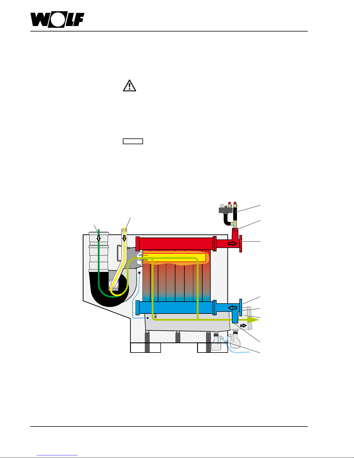
Caution
Safety assembly 2"
(accessory)
Ventilation air pipe
DN200 Connection for
room sealed operation
Gas connection R2"
Condensate trap with
DN250 flue outlet
Test nipple for flue gas
emissions test
Connection R2" for
safety assembly
Connection R2" for BDF
valve (accessory)
Siphons with
condensate drain
Flow connection DN80
/ PN6
Return connection
DN80 / PN6
3063772_201507 19
The MGK-2 is supplied without a circulation pump. The pump rate of the pump to be
supplied by the customer must be determined depending on the system and boiler
pressure drop. The fan's power supply and speed control are via the MGK-2 (see
electrical connection).
The primary and secondary circuit pumps should generally have the same flow rate.
The pumps shown below are designed for a spread of 20 K. If the spread on the
secondary side is smaller, a larger pump must be selected on the primary side. The
maximum flow rates under 4. Specification must be observed.
The following pumps are recommended for the assembly of an MGK-2 with low loss
header.
12. Selection of circulation pumps
Wilo
Nominal ow
rate at 20 K
Spread [m
3
/h]
HE pressure drop
at 20 K
Spread [mbar]
Wilo type
Delivery
head
[mbar]
Residual
head [mbar]
Output
[W]
Current
[A]
Connection
MGK-2
390
17.2 120 Stratos 50/1-2 770 650 590 2.6
1~230V
DN 50 ange tting
MGK-2
470
20.2 113 Stratos 50/1-12 680 567 590 2.6
1~230V
DN 50 ange tting
MGK-2
550
23.7 126 Stratos 65/1-12 730 604 800 3.5
1~230V
DN 65 ange tting
MGK-2
630
26.7 118 Stratos 65/1-12 655 537 800 3.5
1~230V
DN 65 ange tting
Grundfos
Nominal ow
rate at 20 K
Spread [m3/h]
HE pressure drop
at 20 K
Spread [mbar]
Grundfos
Type
Delivery
head
[mbar]
Residual
head [mbar]
Output
[W]
Current
[A]
Connection
MGK-2
390
17.2 120
Magna3
50-120F
730 610 540 2.4
1~230V
DN 50 ange tting
MGK-2
470
20.2 113
Magna3
50-120F
640 527 540 2.4
1~230V
DN 50 ange tting
MGK-2
550
23.7 126
Magna3
50-150F
650 524 630 2.8
1~230V
DN 50 ange tting
MGK-2
630
26.7 118
Magna3
50-180F
680 562 760 3.4
1~230V
DN 50 ange tting
• The maximum power consumption of the circulation pump must not exceed 4 A.
• Reductions from DN80/PN6 to DN/50 or DN65/PN6 are required for the
hydraulic connection of the pumps.
• For the speed control of the circulation pump via the 0-10 V or PWM output of
the boiler control unit, an extension module may be required from the pump
manufacturer.
20 3063772_201507
13. Gas connection
With the power supply disconnected, connect the gas supply line to gas connection
R2" at the gas connection or the expansion joint (recommended) using the approved
sealant.
Routing the gas pipe and making the gas connections must only be
carried out by a licensed gas tter.
Remove all residues from the heating pipework and the gas line prior to
connecting the condensing boiler, particularly in older systems. Prior to
commissioning, test all pipe and gas connections for leaks. Inappropriate
installation or using unsuitable components or assemblies may lead to
gas escaping, which results in a risk of poisoning and explosion.
Install a gas ball valve with re protection in the gas supply line upstream
of the Wolf condensing boiler. Otherwise explosions may occur during a
re. Size the gas supply line in accordance with DVGW-TRGI regulations.
Check the gas line for tightness without the boiler. Never release the
test pressure via the gas valve.
Gas ttings on the appliance should be pressure tested to a
maximum of 150 mbar.Higher pressure may damage the gas train,
resulting in a risk of explosion, suffocation or poisoning. Close the
gas ball valve on the gas condensing boiler to pressure test the gas
line.
Mount the gas ball valve in an easily accessible place.
• Prior to installation, ensure that the boiler is set to the available gas type.
At the factory, the boiler is set up for natural gas E/H 15.0:
Ws = 11.4 - 15.2 kWh/m3 = 40.9 - 54.7 MJ/m
3
Only commission the appliance when the rated supply pressure has been reached.
If the supply pressure for natural gas (flow pressure) lies outside the
18 to 25 mbar range, adjustments must not be carried out and the boiler
must not be put into operation.
Caution
Gas connection R2"
3063772_201507 21
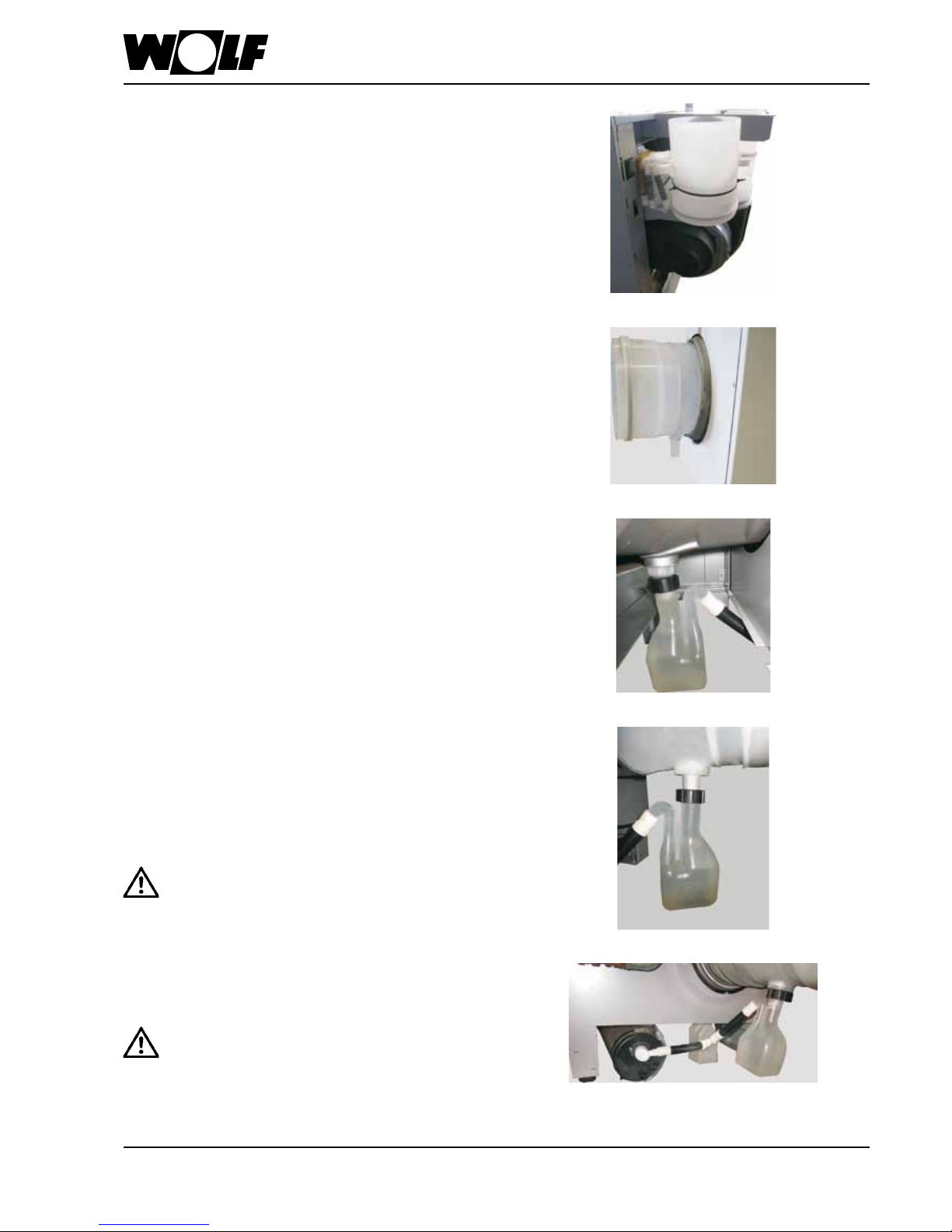
14. Fitting the siphons
Install siphons:
Install the first siphon on the connector of the condensate pan.
Install the second siphon on the connector of the condensate
trap.
Fill the siphons with water prior to
commissioning. Otherwise there is a risk of flue
gas escaping.
Connect the condensate hoses of both siphons from the
condensate pan and condensate trap with a tee and connect
to the neutralising system.
Check tightness of the connections.
The standard delivery includes:
1 x condensate trap (under the burner hood on the
ventilation air pipe)
2 x siphons with 3 condensate hoses and 1 tee (on the
condensate trap)
Condensate connection:
Install condensate trap in the flue outlet of the condensate pan.
Check tightness of the connections.
 Loading...