

Page 1

DROP DOWN DOOR MICROWAVE OVENS
INSTALLATION GUIDE
GUÍA DE INSTALACIÓN
GUIDE D’INSTALLATION
GUIDA ALL’INSTALLAZIONE
INSTALLATIONSANLEITUNG
INSTALLATIEHANDLEIDING
Page 2
DROP DOWN DOOR MICROWAVE OVENS
Contents
2 Drop Down Door Microwave Ovens
3 Specications
4 Installation
4 Troubleshooting
Features and specications are subject to change at any
time without notice.
Important Note
To ensure this product is installed and operated as safely
and efciently as possible, take note of the following types
of highlighted information throughout this guide:
IMPORTANT NOTE highlights information that is especially
important.
CAUTION indicates a situation where minor injury or product
damage may occur if instructions are not followed.
WARNING states a hazard that may cause serious injury or
death if precautions are not followed.
IMPORTANT NOTE: Save these instructions for the local
electrical inspector.
Product Information
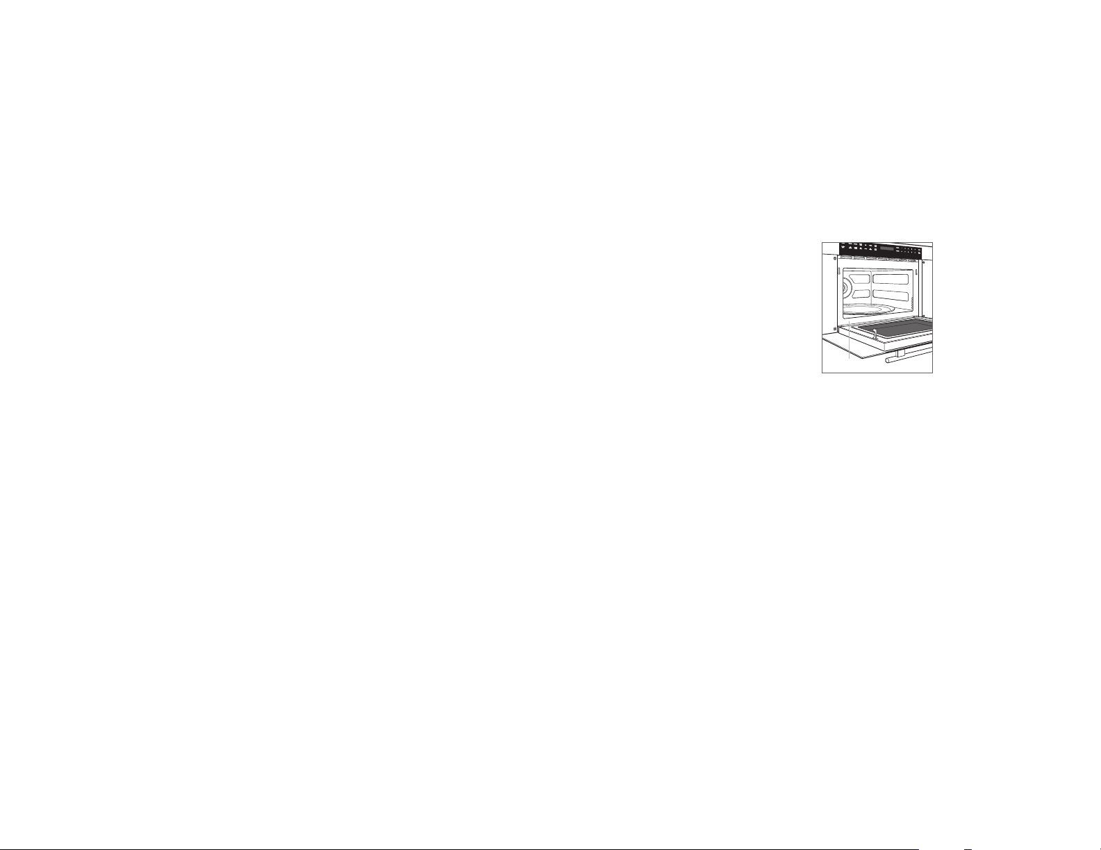
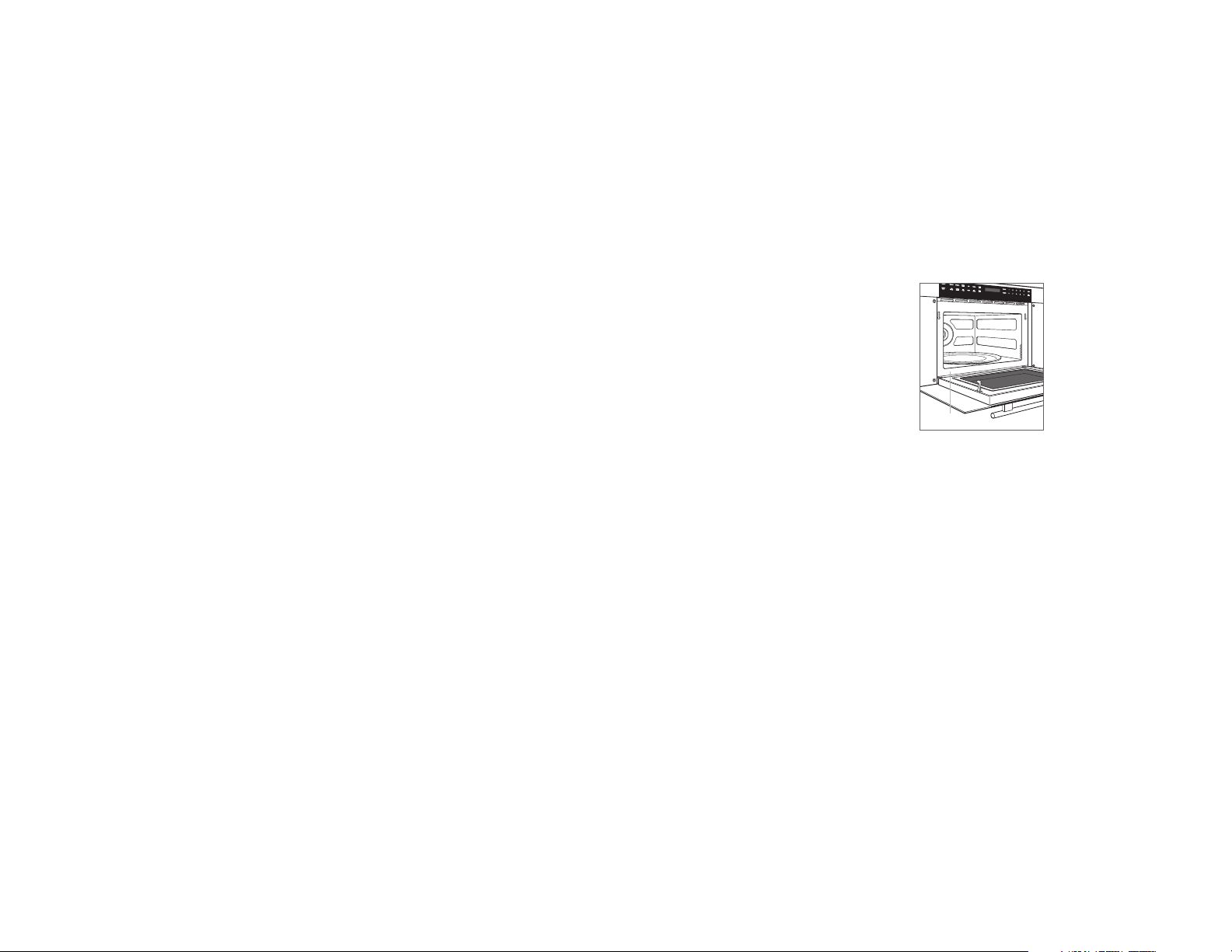
Important product information including the model and
serial number are listed on the product rating plate. The
rating plate is located on the lower left side of the front face
frame. The oven door must be open to view the rating plate.
Refer to the illustration below.
If service is necessary, contact Wolf factory certied service
with the model and serial number.
RATING PLATE
Rating plate location.
2 | English
Page 3
SPECIFICATIONS
SIDE
NOTE: 610 mm and 762 mm models require the same opening dimensions
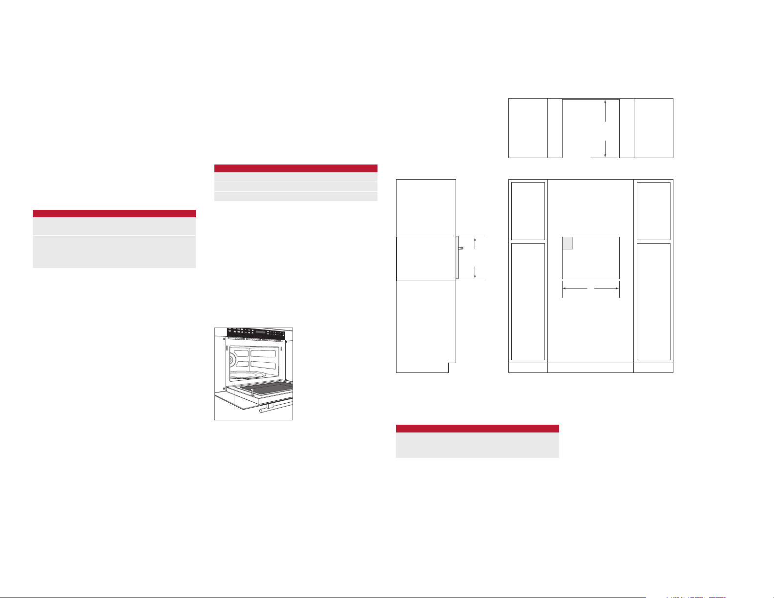
Installation Requirements
The drop down door microwave oven can be installed in a
standard or ush inset application.
Finish the edges of the opening. They may be visible when
the door is open.
For standard installations, face trim will overlap stiles and
rails. Refer to the chart.
For ush inset installations, a minimum 3 mm reveal is
required on all sides. To ensure consistent reveals, each
corner of the opening must be exactly 90°.
If the drop down door microwave oven is installed above or
below a Wolf E series oven in a ush inset application, a 6
mm reveal is required.
INSTALLATION REQUIREMENTS
BASE SUPPORT MIN
Drop Down Door Microwave 57 kg
TRIM OVERLAP 610 mm MODEL 762 mm MODEL
Top 5 mm 5 mm
Bottom 0 mm 0 mm
Sides 18 mm 98 mm
Electrical
Installation must comply with all applicable electrical codes
and be properly grounded (earthed).
Locate the electrical supply as shown in the illustrations on
the following pages. The receptacle may also be located
in an adjacent cabinet within reach of the power cord. A
separate circuit, servicing only this appliance is required. A
ground fault circuit interrupter (GFCI) is not recommended
and may cause interruption of operation.
ELECTRICAL REQUIREMENTS
Electrical Supply 220-240V, 50Hz
Service 1600 Watts
Power Cord 1.2 m
IMPORTANT NOTE: Connection of this appliance should be
through a fused connection unit or a suitable isolator, which
complies with national and local safety regulations. The
on/off switch should be easily accessible after the appliance has been installed. If the switch is not accessible after
installation (depending on country) an additional means of
disconnection must be provided for all poles of the power
supply. When switched off there must be an all pole contact
gap of 3 mm in the isolator switch. This 3 mm contact disconnect gap must apply to any isolator switch, fuses and/or
relays according to EN60335.
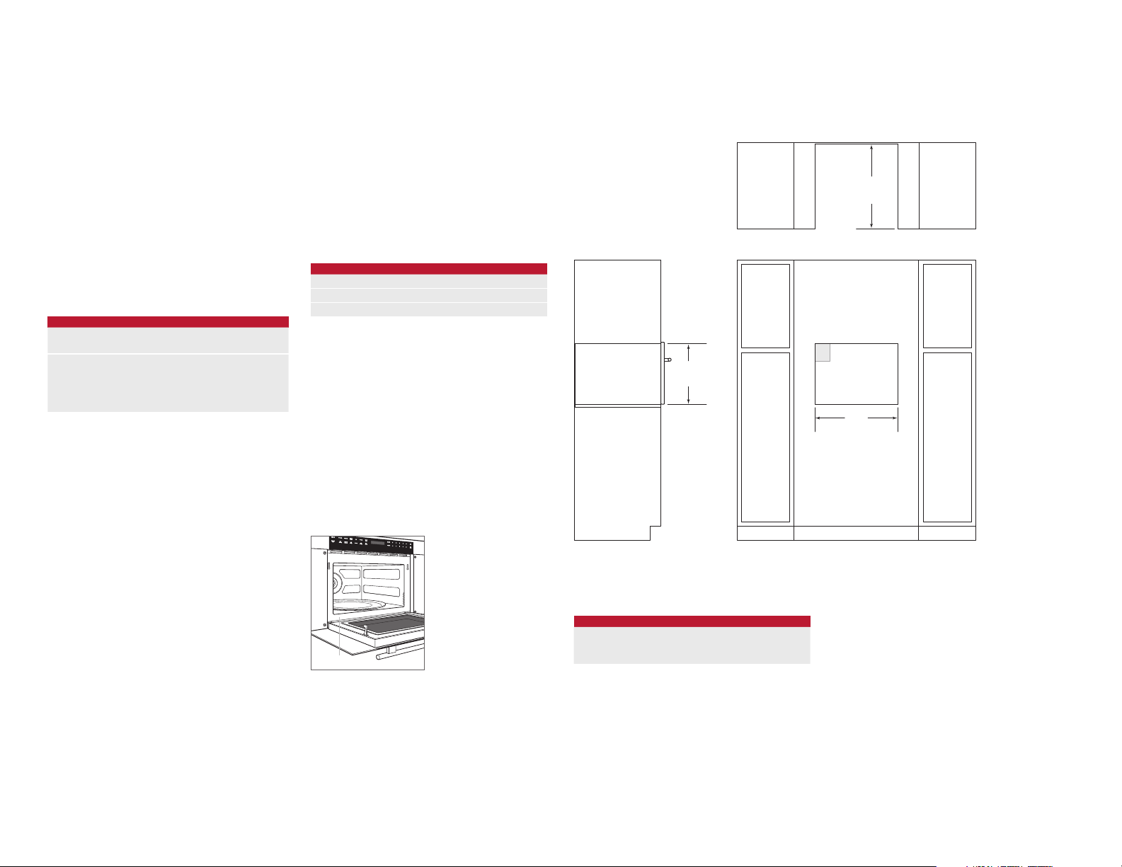
Drop Down Door Microwave Oven
STANDARD INSTALLATION
449 mm
OPENING
HEIGHT
TOP VIEW
E
OPENING WIDTH
W
548 mm
OPENING
DEPTH
RATING PLATE
Rating plate location.
VIEW
.
OPENING WIDTH
MICROWAVE OVEN W
610 mm Model 562 mm
762 mm Model 562 mm
FRONT VIEW
wolfappliance.com | 3
Page 4
SPECIFICATIONS
INSTALLATION
Drop Down Door Microwave Oven
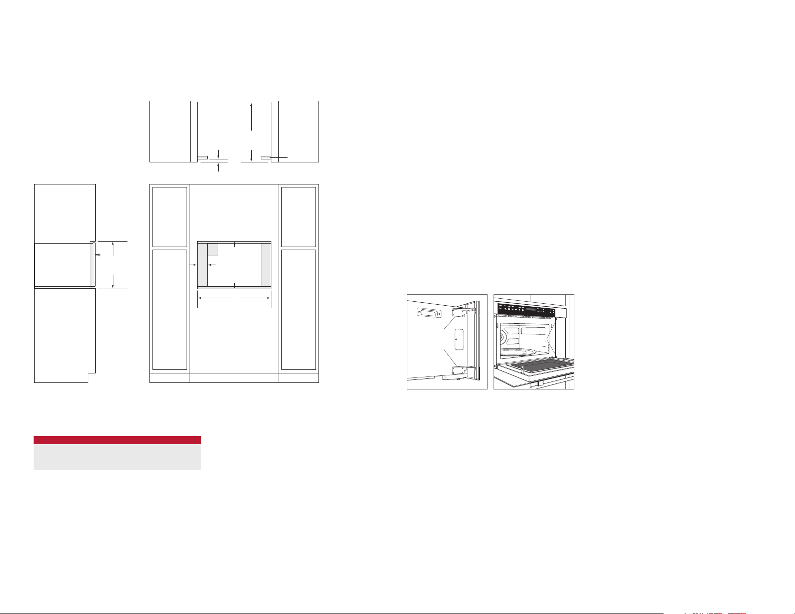
FLUSH INSET INSTALLATION
460 mm
FLUSH INSET
HEIGHT**
22 mm
TOP VIEW
E
8 mm
A
3 mm
FLUSH INSET WIDTH**
584 mm
FLUSH INSET
DEPTH
W
FINISHED
CLEATS*
Installation
1 Turn power off to the electrical outlet.
2 Move the unit near the opening. Remove and recycle
packing materials.
3 The unit is shipped with two shipping brackets located
on each side, behind the front face. Remove both
brackets, then reinstall screws. Refer to the illustration
below.
4 Connect the appliance to the xed wiring.
5 Position the microwave oven in the opening and slide
back until the mounting ange is ush with the face of
the cabinet. Avoid pinching the power cord between the
unit and cabinet wall.
6 Open the door. Using the two holes on either side of the
mounting ange as a template, drill pilot holes into the
cabinet.
7 Mount the microwave oven using four screws provided.
Refer to the illustration below.
8 Turn power back on to the electrical outlet.
REMOVE
BRACKETS
THEN REINSTALL
SCREWS
MOUNTING
SCREWS
Troubleshooting
IMPORTANT NOTE: If the drop down door microwave oven
does not operate properly, follow these troubleshooting
steps:
• Verify electrical power is supplied to the microwave
oven.
• Verify proper electrical connections.
• If the microwave oven does not operate properly, contact
Wolf factory certied service. Do not attempt to repair
the oven. Wolf is not responsible for service required to
correct a faulty installation.
*Will be visible and should be finished to match cabinetry.
**Dimension provides minimum reveals.
OPENING WIDTH
MICROWAVE OVEN W A
610 mm Model 603 mm 21 mm
762 mm Model 765 mm 102 mm
4 | English
FRONT VIEWSIDE VIEW
Shipping brackets.
Mounting screws.
Page 5

Wolf, Wolf & Design, Wolf Gourmet, W & Design and the color red as applied to knobs are registered trademarks and service marks of Wolf Appliance, Inc. Sub-Zero, Sub-Zero & Design, Dual Refrigeration, The Living Kitchen, Great American Kitchens The Fine Art of Kitchen Design, and Ingredients are registered trademarks and service marks of Sub-Zero, Inc. All other
trademarks or registered trademarks are property of their respective owners in the United States and other countries.
wolfappliance.com | 5
Page 6
HORNOS MICROONDAS DE PUERTA ABATIBLE
Índice
2 Hornos microondas de puerta abatible
3 Especicaciones
4 Instalación
4 Localización y solución de problemas
Las características y especicaciones están sujetas a
cambios sin previo aviso.
Nota importante:
Para garantizar que este producto se instala y funciona de
la forma más ecaz y segura posible, tenga en cuenta la
información que se destaca en esta guía:
Cuando aparece
que resulta especialmente importante.
PRECAUCIÓN indica una situación en la que se pueden
sufrir heridas leves o provocar daños al producto si no se
siguen las instrucciones.
AVISO indica el peligro de que se produzcan heridas graves
o incluso la muerte si no se respetan las precauciones.
NOTA IMPORTANTE: conserve estas instrucciones para el
inspector eléctrico local.
NOTA IMPORTANTE, se resalta información
Información sobre el producto
En la placa de datos del producto encontrará información
importante, incluyendo el modelo y el número de serie. La
placa de datos está ubicada en el lado inferior izquierdo del
marco frontal. La puerta del horno debe estar abierta para
ver la placa de datos. Observe la siguiente ilustración.
Si necesita recurrir a un servicio técnico, póngase en contacto con un servicio de Wolf certicado con el modelo y el
número de serie.
PLACA DE DATOS
Ubicación de la placa de datos.
2 | Español
Page 7
ESPECIFICACIONES
VIST
NOTA: Los modelos de 610 mm y 762 mm necesitan las mismas dimensiones de apertura
Requisitos de instalación
El horno microondas de puerta abatible puede instalarse en
una aplicación estándar o empotrable.
Remate los bordes de la cavidad, pues son áreas que
pueden resultar muy visibles al abrir la puerta.
Para instalaciones estándar, el contramarco frontal irá
superpuesto sobre los raíles y montantes. Consulte la tabla.
Para instalaciones empotrables, es necesario un margen
mínimo de 3 mm en todos los lados. Para garantizar unos
márgenes consistentes, cada esquina de la cavidad debe
tener exactamente 90º.
Si el horno microondas de puerta abatible se instala encima
o debajo de un horno Wolf de la Serie E en una aplicación
empotrable, es necesario utilizar un margen de 6 mm.
REQUISITOS DE INSTALACIÓN
SOPORTE DE LA BASE MÍN.
Microondas de puerta abatible 57 kg
SUPERPOSICIÓN DEL MARCO MODELO DE
Superior 5 mm 5 mm
Inferior 0 mm 0 mm
Lados 18 mm 98 mm
610 mm
MODELO DE 762
mm
Potencia
La instalación debe cumplir con todas las normativas eléctricas aplicables y debe estar correctamente conectada a
tierra.
Ubique la toma eléctrica tal como se muestra en las ilustraciones de las siguientes páginas. La toma también puede
colocarse en un armario contiguo cerca del cable eléctrico.
Se necesita un circuito independiente para esta unidad. No
se recomienda utilizar un interruptor de circuito de fallos de
toma de tierra (GFCI), ya que puede interrumpir el funcionamiento de la unidad.
REQUISITOS ELÉCTRICOS
Suministro eléctrico 220-240V, 50Hz
Servicio 1600 Vatios
Cable eléctrico 1,2 m
NOTA IMPORTANTE: la conexión de este aparato debe reali-
zarse a una unidad de conexión con fusibles o a un aislador
adecuado, que cumpla con las normativas de seguridad
nacionales y locales. El interruptor de encendido/apagado
debe encontrarse en un lugar accesible después de haber
instalado el aparato. Si no es posible acceder al interruptor
después de la instalación (según el país), se deberá suministrar un medio de desconexión adicional para todos los
polos de la alimentación eléctrica. Al estar desconectado,
deberá existir una separación de contacto entre todos los
polos de 3 mm en el interruptor del aislador. Esta separación de 3 mm de desconexión de los contactos deberá
aplicarse a cualquier interruptor, fusibles o relés del aislador
según la norma EN60335.
Horno microondas de puerta abatible
INSTALACIÓN ESTÁNDAR
449 mm
ALTURA DE
LA CAVIDAD
548 mm
PROFUNDIDAD
DE LA CAVIDAD
VISTA SUPERIOR
E
Anch.
ANCHURA DE LA CAVIDAD
PLACA DE DATOS
Ubicación de la placa de datos.
A LATERAL
ANCHURA DE LA CAVIDAD
HORNO MICROONDAS Anch.
Modelo de 610 mm 562 mm
Modelo de 762 mm 562 mm
VISTA FRONTAL
.
wolfappliance.com | 3
Page 8

ESPECIFICACIONES
INSTALACIÓN
Horno microondas de puerta abatible
INSTALACIÓN EMPOTRABLE
460 mm
ALTURA DE
INSTALACIÓN
EMPOTRABLE**
584 mm
PROFUNDIDAD DE
INSTALACIÓN
EMPOTRABLE
22 mm
VISTA SUPERIOR
E
8 mm
A
3 mm
Anch.
ANCHURA DE INSTALACIÓN
EMPOTRABLE**
LISTONES
ACABADOS*
Instalación
1 Desconecte el aparato de la red eléctrica.
2 Desplace la unidad hasta un lugar cerca de la cavidad.
Quite y recicle los materiales de embalaje.
3 La unidad se envía con dos soportes de envío situados
en cada lateral, detrás de la parte frontal. Quite ambos
soportes y luego vuelva a colocar los tornillos. Observe
la siguiente ilustración.
4 Conecte el aparato al cableado jo.
5 Coloque el horno microondas en la cavidad y deslícelo
hacia atrás hasta que la brida de montaje quede nivelada
con la parte frontal del armario. Evite pillar el cable entre
la unidad y la pared del armario.
6 Abra la puerta. Utilizando los dos oricios situados en
cada lado de la brida de montaje como plantilla, taladre
los oricios guía en el armario.
7 Monte el horno microondas utilizando los tornillos sumi-
nistrados. Observe la siguiente ilustración.
8 Vuelva a conectar la unidad a la red eléctrica.
QUITE LOS
SOPORTES Y
LUEGO VUELVA
A COLOCAR
LOS TORNILLOS
TORNILLOS
DE MONTAJE
Localización y solución de problemas
NOTA IMPORTANTE: si el horno microondas de puerta
abatible no funciona correctamente, siga estos pasos de
localización y solución de problemas:
• Compruebe que el horno microondas está conectado a
la red eléctrica.
• Compruebe que las conexiones eléctricas son correctas.
• Si el horno microondas no funciona correctamente, pón-
gase en contacto con un servicio de asistencia técnica
autorizado de Wolf. No realice ninguna reparación en
el horno. Wolf no se hace responsable de las tareas de
mantenimiento que deban realizarse para corregir una
instalación defectuosa.
*Serán visibles y deberán acabarse para que coincidan con los muebles.
**La medida ofrece unos márgenes mínimos.
ANCHURA DE LA CAVIDAD
HORNO MICROONDAS Anch. A
Modelo de 610 mm 603 mm 21 mm
Modelo de 762 mm 765 mm 102 mm
4 | Español
VISTA FRONTALVISTA LATERAL
Soportes de envío.
Tornillos de montaje.
Page 9

Wolf, Wolf & Design, Wolf Gourmet, W & Design y los mandos distintivos de color rojo son marcas registradas y marcas de servicio de Wolf Appliance, Inc. Sub-Zero, Sub-Zero & Design, Dual Refrigeration, The Living Kitchen, Great American Kitchens The Fine Art of Kitchen Design, and Ingredients son marcas registradas y marcas de servicio de Sub-Zero, Inc.
Todas las demás marcas o marcas registradas son propiedad de sus respectivos propietarios en los Estados Unidos y en otros países.
wolfappliance.com | 5
Page 10

FOURS MICRO-ONDES À PORTE ABATTANTE
Table des matières
2 Fours micro-ondes à porte abattante
3 Spécications
4 Installation
4 Dépistage des pannes
Les caractéristiques et spécications peuvent être modiées
à tout moment sans préavis.
Remarque importante
Pour garantir une installation de ce produit aussi sûre et efcace que possible, veuillez faire particulièrement attention
aux mentions mises en évidence tout au long de ce guide,
notamment :
REMARQUE IMPORTANTE met l’accent sur un renseigne-
ment particulièrement important.
MISE EN GARDE signale un danger qui pourrait causer une
blessure mineure ou endommager le produit si vous ne
suivez pas les instructions.
AVERTISSEMENT signale un danger qui pourrait causer
des blessures graves voire fatales si vous ne prenez pas
certaines précautions.
REMARQUE IMPORTANTE : Conservez ces instructions pour
l’électricien local chargé des inspections.
Information concernant le produit
Les renseignements importants concernant le produit,
notamment la référence modèle et le numéro de série,
gurent sur la plaque des caractéristiques du produit.
La plaque des caractéristiques est située sur le côté
gauche inférieur du cadre de la face avant. Vous devez
ouvrir la porte du four pour voir la plaque des caractéristiques. Reportez-vous à l’illustration ci-après.
Si vous devez contacter le service après-vente, contactez
le prestataire agréé par l’usine Wolf avec les numéros de
modèle et de série.
PLAQUE DES
CARACTÉRISTIQUES
Emplacement de la plaque des
caractéristiques.
2 | Français
Page 11

SPÉCIFICATIONS
VUE LA
REMARQUE : Les modèles de 610 mm et de 762 mm exigent les mêmes dimensions d'ouverture
Exigences relatives à l’installation
Le four micro-ondes à porte abattante peut être installé en
version normale ou avec panneau d’afeurement.
Finissez les bords de l’ouverture. Ils pourraient être visibles
lorsque la porte est ouverte.
Pour les versions normales, la moulure frontale empiète sur
les montants et les rails. Reportez-vous au tableau.
Pour les versions avec panneaux d’afeurement, il faut
prévoir au moins 3 mm de tous les côtés. Pour garantir des
espaces constants, chaque coin de l’ouverture doit être en
angle droit parfait.
Si le four micro-ondes à porte abattante est installé audessus ou en-dessous d’un four de la série Wolf E avec
panneau d’afeurement, alors un espace de 6 mm est
requis.
EXIGENCES RELATIVES À L’INSTALLATION
SUPPORT DE LA BASE MIN
Four micro-ondes à porte abattante 57 kg
EMPIÈTEMENT DE LA MOULURE Modèle de
Haut 5 mm 5 mm
Bas 0 mm 0 mm
Côtés 18 mm 98 mm
610 mm
Modèle de
762 mm
Électricité
L’installation doit se conformer à tous les codes électriques
applicables. Elle doit être correctement mise à la terre.
Identiez l’alimentation électrique comme indiqué sur les
illustrations des pages suivantes. La prise peut être placée
dans un élément de cuisine adjacent, à portée du cordon
d’alimentation. Il est nécessaire d’avoir un circuit indépendant, alimentant uniquement cet appareil ménager. Il n’est
pas recommandé d’avoir recours à un disjoncteur différentiel (GFCI) qui pourrait provoquer l’interruption du fonctionnement de l’appareil.
CONFIGURATION ÉLECTRIQUE
Alimentation électrique 220-240V, 50Hz
Service 1600 Watts
Cordon d’alimentation 1,2 m
REMARQUE IMPORTANTE : Le branchement de cet
appareil ménager doit se faire par le biais d’une prise avec
fusible de protection ou un sectionneur adapté conformément à la règlementation nationale et locale en matière de
sécurité électrique. On doit pouvoir accéder facilement
à l’interrupteur une fois l’appareil ménager installé. Si ce
n’est pas le cas, il faudra, en fonction de la réglementation
en vigueur dans le pays, fournir un moyen supplémentaire
de déconnecter tous les pôles de l’alimentation. Une fois
déconnecté, il doit y avoir une distance de 3 mm entre les
contacts des pôles dans le sectionneur. Cet écart de 3 mm
entre les contacts des pôles doit s’appliquer à tout sectionneur, fusible ou relais conformément à la norme EN60335.
Four micro-ondes à porte abattante
INSTALLATION STANDARD
449 mm
HAUTEUR
D'OUVERTURE
548 mm
PROFONDEUR
D'OUVERTURE
VUE EN PLAN
E
W
LARGEUR D'OUVERTURE
PLAQUE DES
CARACTÉRISTIQUES
Emplacement de la plaque des
caractéristiques.
TÉRALE
LARGEUR D’OUVERTURE
FOUR MICRO-ONDES L
Modèle de 610 mm 562 mm
Modèle de 762 mm 562 mm
VUE DE FACE
.
wolfappliance.com | 3
Page 12

SPÉCIFICATIONS
INSTALLATION
Four micro-ondes à porte abattante
INSTALLATION AVEC PANNEAU D’AFFLEUREMENT
460 mm
HAUTEUR
DU PANNEAU
D’AFFLEUREMENT
**
PROFONDEUR
DU PANNEAU
D'AFFLEUREMENT
22 mm
VUE EN PLAN
E
8 mm
A
3 mm
W
LARGEUR DU PANNEAU
D’AFFLEUREMENT**
584 mm
TASSEAUX
FINIS*
Installation
1 Coupez le courant à la prise électrique.
2 Placez l’appareil près de l’ouverture. Retirez et recyclez
les matériaux d’emballage.
3 L’appareil a été expédié avec deux supports d’expédi-
tion situés de chaque côté, derrière la face avant. Retirez
les deux supports puis remettez les vis. Reportez-vous à
l’illustration ci-après.
4 Branchez l’appareil au câblage xe.
5 Placez le four micro-ondes dans l’ouverture et faites-le
glisser jusqu’à ce que la bride de xation soit à eur
de la face de l’élément de cuisine. Évitez de pincer
le cordon entre l’appareil et la paroi de l’élément de
cuisine.
6 Ouvrez la porte. En utilisant comme gabarit les deux
trous de chaque côté de la bride de xation, percez des
avant-trous dans l’élément de cuisine.
7 Fixez le four micro-ondes en utilisant les quatre vis four-
nies. Reportez-vous à l’illustration ci-après.
8 Rétablissez le courant à la prise électrique.
RETIRER LES
SUPPORTS PUIR
REMETTRE LES VIS
VIS DE
MONTAGE
Dépistage des pannes
REMARQUE IMPORTANTE : Si le four micro-ondes à porte
abattante ne fonctionne pas correctement, suivez les étapes
de dépistage des pannes suivantes :
• Vériez si l’alimentation électrique arrive au four
micro-ondes.
• Vériez que les branchements électriques sont bien faits.
• Si le four micro-ondes ne fonctionne pas correcte-
ment, contactez un prestataire agréé par l’usine Wolf.
N’essayez pas de réparer le four. Wolf ne peut être tenue
responsable des dépannages requis en raison d’une
mauvaise installation.
*Seront visibles et doivent être finis pour être assortis aux éléments de cuisine.
**Les dimensions tiennent compte des espaces minimums.
LARGEUR D’OUVERTURE
FOUR MICRO-ONDES L A
Modèle de 610 mm 603 mm 21 mm
Modèle de 762 mm 765 mm 102 mm
4 | Français
VUE DE FACEVUE LATÉRALE
Support d’expédition
Vis de xation
Page 13

Wolf, Wolf & Design, Wolf Gourmet, W & Design et la couleur rouge comme celle qui est appliquée aux boutons sont des marques déposées et des marques de services de Wolf Appliance, Inc. Sub-Zero, Sub-Zero & Design, Dual Refrigeration, The Living Kitchen, Great American Kitchens The Fine Art of Kitchen Design et Ingredients sont des marques déposées et des
marques de services de Sub-Zero, Inc. Toutes les autres marques de commerce ou marques déposées ont été brevetées par leurs propriétaires respectifs aux États-Unis ou dans d’autres pays.
wolfappliance.com | 5
Page 14

FORNI A MICROONDE CON APERTURA VERSO IL BASSO
Indice
2 Forni a microonde con apertura verso il basso
3 Speciche
4 Installazione
4 Risoluzione problemi
Le caratteristiche e le speciche sono soggette a modiche
in qualsiasi momento, senza obbligo di preavviso.
Nota importante
Per garantire un’installazione e un funzionamento sicuri ed
efcaci del prodotto, prestare attenzione alle seguenti informazioni evidenziate all’interno della guida:
NOTA IMPORTANTE evidenzia informazioni di particolare
rilievo.
ATTENZIONE indica una situazione in cui possono vericarsi
lesioni e danni di lieve entità al prodotto, in caso di mancata
osservanza delle istruzioni.
AVVERTENZA indica un rischio che potrebbe causare gravi
lesioni o morte in caso di mancata osservanza delle precauzioni.
NOTA IMPORTANTE: conservare le istruzioni per l’elettricista
locale.
Informazioni sul prodotto
Importanti informazioni sul prodotto, incluso modello e
numero di serie, si trovano sulla targhetta identicativa del
prodotto. La targhetta identicativa è situata in basso, sul
lato sinistro anteriore della cornice. Per vedere la targhetta
identicativa, è necessario aprire lo sportello del forno. Fare
riferimento alla gura riportata di seguito.
Se si rende necessaria l’assistenza, prendere contatto
con un servizio di assistenza certicato Wolf specicando
modello e numero di serie.
TARGHETTA
IDENTIFICATIVA
Posizione della targhetta identicativa.
2 | Italiano
Page 15

SPECIFICHE
VIST
NOTA: i modelli da 610 mm e da 762 mm richiedono le stesse dimensioni del vano
Requisiti di installazione
Il forno a microonde con apertura verso il basso è indicato
per l’installazione standard o a lo.
Rinire i bordi del vano. Possono infatti essere visibili
quando la porta è aperta.
Per le installazioni standard, la cornice si sovrappone ai
montanti verticali e alle guide. Consultare la tabella.
Per le installazioni a lo, è necessario uno spazio minimo di
3 mm su tutti i lati. Per assicurare uniformità di spazio, ogni
angolo del vano di incasso deve essere esattamente di 90°.
Se il forno a microonde con apertura verso il basso è installato a lo sopra o sotto un forno Wolf serie E, è necessario
mantenere uno spazio di almeno 6 mm.
REQUISITI PER L’INSTALLAZIONE
SUPPORTO BASE MIN
Forno a microonde con
apertura verso il basso
SOVRAPPOSIZIONE DELLA
CORNICE
In alto 5 mm 5 mm
In basso 0 mm 0 mm
Ai lati 18 mm 98 mm
MODELLO 610 mmMODELLO 762
57 kg
mm
Alimentazione elettrica
L’installazione deve essere conforme alle normative elettriche vigenti in materia e prevedere un’adeguata linea di
messa a terra.
Individuare la presa di alimentazione elettrica come illustrato nelle gure nelle pagine che seguono. È possibile
posizionare la custodia in un pensile adiacente entro la
portata del cavo di alimentazione. Per questo elettrodomestico, è necessario predisporre un circuito elettrico dedicato. Si sconsiglia l’utilizzo di un interruttore automatico
salvavita (GFCI) in quanto potrebbe causare problemi di
funzionamento.
REQUISITI ELETTRICI
Alimentazione elettrica 220-240 V, 50 Hz
Potenza 1600 Watt
Cavo di alimentazione 1,2 m
NOTA IMPORTANTE: questo elettrodomestico va collegato
all’alimentazione tramite una connessione dotata di fusibili o
un adeguato interruttore di isolamento, conforme alle vigenti
normative di sicurezza nazionali e locali. L’interruttore on/off
deve essere facilmente raggiungibile in seguito all’installazione dell’elettrodomestico. Se dopo l’installazione, l’interruttore non è accessibile, sarà necessario installare (in base
alle normative del proprio paese) un ulteriore dispositivo per
scollegare tutti i poli dell’alimentazione. Quando è scollegato, tutti i poli all’interno del sezionatore devono presentare
uno spazio libero di contatto di almeno 3 mm. Lo spazio
libero di contatto di 3 mm deve essere rispettato in tutti gli
interruttori di isolamento, fusibili e/o relè in ottemperanza
alla normativa EN60335.
Forno a microonde con apertura verso il basso
INSTALLAZIONE STANDARD
449 mm
ALTEZZA
VANO INCASSO
548 mm
PROFONDITÀ
VANO INCASSO
VISTA DALL'ALTO
E
L
LARGHEZZA VANO
INCASSO
TARGHETTA
IDENTIFICATIVA
Posizione della targhetta
identicativa.
A LATERALE
LARGHEZZA VANO INCASSO
FORNO A MICROONDE L
Modello 610 mm 562 mm
Modello 762 mm 562 mm
VISTA FRONTALE
.
wolfappliance.com | 3
Page 16

SPECIFICHE
INSTALLAZIONE
Forno a microonde con apertura verso il basso
INSTALLAZIONE A FILO
460 mm
ALTEZZA CON
INSERTI A FILO**
584 mm
PROFONDITÀ CON
INSERTI A FILO
22 mm
VISTA DALL'ALTO
E
8 mm
A
3 mm
L
LARGHEZZA CON INSERTI
A FILO**
PROFILI DI
TAMPONATURA*
FINITI
Installazione
1 Disattivare l’alimentazione dalla presa elettrica.
2 Sostare l’unità vicino al vano di incasso. Rimuovere e
smaltire il materiale di imballaggio.
3 L’unità viene spedita con due staffe di trasporto, una su
ogni lato, dietro al fronte. Rimuovere entrambe le staffe,
quindi riposizionare le viti. Fare riferimento alla gura
riportata di seguito.
4 Collegare l’elettrodomestico al cablaggio sso.
5 Posizionare il forno a microonde nel vano di incasso e
spingerlo no a che la angia di montaggio non è allineata alla parte anteriore del mobile. Evitare di schiacciare il cavo di alimentazione tra l’unità e la parete del
mobile.
6 Aprire lo sportello. Facendo uso dei due fori sui lati della
angia di montaggio come riferimento, praticare dei fori
guida nel mobile.
7 Montare il forno a microonde mediante le quattro viti in
dotazione. Fare riferimento alla gura riportata di seguito.
8 Riallacciare la corrente alla presa elettrica.
RIMUOVERE LE
STAFFE, QUINDI
RIPOSIZIONARE
LE VITI
VITI DI
MONTAGGIO
Risoluzione dei problemi
NOTA IMPORTANTE: se il forno a microonde con apertura
verso il basso non funziona correttamente, effettuare le
seguenti operazioni:
• Vericare l’alimentazione elettrica del forno.
• Vericare la correttezza dei collegamenti elettrici.
• Se il forno non funziona adeguatamente, rivolgersi a
un centro di assistenza autorizzato Wolf. Non tentare
di riparare il forno. Wolf non sarà ritenuta responsabile
dell’assistenza necessaria per correggere un’installazione difettosa.
*Saranno visibili e devono essere rifiniti in modo da abbinarsi ai mobili.
**Le dimensioni forniscono la spaziatura minima.
LARGHEZZA VANO INCASSO
FORNO A MICROONDE L A
Modello 610 mm 603 mm 21 mm
Modello 762 mm 765 mm 102 mm
4 | Italiano
VISTA FRONTALEVISTA LATERALE
Staffe di trasporto.
Viti di montaggio.
Page 17

Wolf, Wolf & Design, Wolf Gourmet, W & Design e il colore rosso applicato alle manopole sono marchi registrati e di servizio di Wolf Appliance, Inc. Sub-Zero, Sub-Zero & Design, Dual Refrigeration, The Living Kitchen, Great American Kitchens, The Fine Art of Kitchen Design e Ingredients sono marchi registrati e di servizio di Sub-Zero, Inc. Tutti gli altri marchi o marchi
registrati sono di proprietà dei rispettivi titolari negli Stati Uniti e in altri paesi.
wolfappliance.com | 5
Page 18

MIKROWELLENHERD MIT HERUNTERKLAPPBARER TÜR
Inhaltsverzeichnis
2 Mikrowellenherde mit herunterklappbarer Tür
3 Technische Daten
4 Installation
4 Fehlersuche
Die Leistungsmerkmale und technischen Daten unterliegen
jederzeit Änderungen ohne Vorankündigung.
Wichtiger Hinweis
Um eine möglichst sichere und efziente Installation dieses
Produkts zu gewährleisten, beachten Sie bitte die folgenden
Arten hervorgehobener Informationen in der gesamten
Anleitung:
WICHTIGER HINWEIS hebt Informationen hervor, die beson-
ders wichtig sind.
VORSICHT ist ein Hinweis auf eine Situation, die bei Nicht-
beachtung der Anweisungen zu geringfügigen Personenoder Sachschäden führen kann.
ACHTUNG weist auf eine Gefahr hin, die bei Nichtbeachtung
der Anweisungen zu schweren Verletzungen oder zum Tod
führen kann.
WICHTIGER HINWEIS: Bewahren Sie diese Installationsan-
weisungen für den örtlichen Elektroprüfer auf.
Produktinformationen
Wichtige Produktinformationen, einschließlich der Modellund Seriennummer, sind auf dem Produkttypenschild aufgeführt. Das Typenschild bendet sich auf der unteren linken
Seite des Vorderrahmens. Die Herdtür muss offen sein,
damit das Typenschild sichtbar ist. Siehe Abbildung unten.
Wenn Serviceleistungen erforderlich sind, setzen Sie sich
mit dem zugelassenen Wolf-Kundendienstzentrum mit der
Modell- und Seriennummer in Verbindung.
TYPENSCHILD
Typenschildposition
2 | Deutsch
Page 19

TECHNISCHE DATEN
SEITENANSICH
HINWEIS: Für 610-mm- und 762-mm-Modelle werden dieselben Öffnungsabmessungen benötigt
Installationsvoraussetzungen
Der Mikrowellenherd mit herunterklappbarer Tür kann in
einer standardmäßigen oder bündigen/voll integrierten
Ausführung installiert werden.
Die Kanten der Öffnung müssen endbearbeitet werden.
Sie können sichtbar sein, wenn die Tür geöffnet ist.
Beim Standardeinbau deckt die Umrandung die Ränder und
Schienen ab. Siehe das Diagramm.
Bei bündigen/voll integrierten Installationen ist eine Laibung
von mindestens 3 mm auf allen Seiten erforderlich. Um einheitliche Laibungen zu gewährleisten, muss jede Ecke der
Öffnung einen Winkel von genau 90° aufweisen.
Wenn der Mikrowellenherd mit herunterklappbarer Tür über
oder unter einem Wolf-Ofen der E-Serie installiert wird, ist
eine Laibung von 6 mm erforderlich.
INSTALLATIONSVORAUSSETZUNGEN
TRAGFÄHIGKEIT DES
SOCKELS
Mikrowellenherd mit herunterklappbarer Tür
KANTENÜBERSTAND 610-mm-
Oben 5 mm 5 mm
Unten 0 mm 0 mm
Seiten 18 mm 98 mm
MODELL
MIN
57 kg
762-mmMODELL
Elektrik
Bei der Installation müssen alle geltenden elektrischen
Vorschriften eingehalten werden und die Geräte müssen
ordnungsgemäß geerdet werden.
Installieren Sie die Stromversorgung im Bereich, der in den
Zeichnungen auf den folgenden Seiten dargestellt ist. Die
Steckdose kann auch in einem angrenzenden Schrank
innerhalb der Reichweite des Netzkabels untergebracht
sein. Außerdem ist ein separater Stromkreis nur für dieses
Gerät erforderlich. Ein FI-Schutzschalter wird nicht
empfohlen und kann den Betrieb unterbrechen.
ELEKTROVORAUSSETZUNGEN
Stromversorgung 220-240V, 50Hz
Service 1600 Watt
Netzkabel 1,2 m
WICHTIGER HINWEIS: Der Anschluss dieses Geräts sollte
über ein Sicherungsmodul oder einen geeigneten Trennschalter vorgenommen werden, das bzw. der den nationalen
und örtlichen Sicherheitsvorschriften entspricht. Der Ein-/
Aus-Schalter sollte nach der Installation des Geräts leicht
zugänglich sein. Wenn der Schalter nach der Installation
nicht zugänglich ist (je nach Land), muss für alle Pole
der Stromversorgung eine zusätzliche Trennvorrichtung
bereitgestellt werden. Im ausgeschalteten Zustand muss
im Trennschalter ein allpoliger Kontaktabstand von 3 mm
vorhanden sein. Dieser 3-mm-Kontakttrennabstand muss
für alle Trennschalter, Sicherungen und/oder Relais gemäß
EN60335 eingehalten werden.
Mikrowellenherd mit herunterklappbarer Tür
STANDARDINSTALLATION
ÖFFNUNGSHÖHE
449 mm
ÖFFNUNGSTIEFE
548 mm
DRAUFSICHT
E
W
ÖFFNUNGSBREITE
TYPENSCHILD
Typenschildposition
T
ÖFFNUNGSBREITE
MIKROWELLENHERD B
610-mm-Modell 562 mm
762-mm-Modell 562 mm
VORDERANSICHT
.
wolfappliance.com | 3
Page 20

TECHNISCHE DATEN
INSTALLATION
Mikrowellenherd mit herunterklappbarer Tür
BÜNDIGE/VOLL INTEGRIERTE INSTALLATION
BÜNDIGE/VOLL
INTEGRIERTE
HÖHE**
460 mm
BÜNDIGE/VOLL
INTEGRIERTE
DRAUFSICHT
8 mm
3 mm
W
BREITE**
TIEFE
584 mm
22 mm
E
A
BÜNDIGE/VOLL INTEGRIERTE
ENDBEARBEITETE
SCHLAGLEISTEN*
Installation
1 Die Stromzufuhr zur Steckdose unterbrechen.
2 Das Gerät in der Nähe der Öffnung positionieren. Die
Verpackungsmaterialien entfernen und dem Recycling
zuführen.
3 Das Gerät wird mit zwei Versandhalterungen geliefert, die
sich hinter der Vorderseite auf beiden Seiten benden.
Beide Halterungen entfernen, dann die Schrauben
wieder einbauen. Siehe Abbildung unten.
4 Das Gerät an die feste Verdrahtung anschließen.
5 Den Mikrowellenherd in die Öffnung positionieren und so
weit zurückschieben, bis der Montageansch bündig an
der Schrankvorderseite anliegt. Das Netzkabel darf nicht
zwischen Gerät und Schrankwand gequetscht werden.
6 Öffnen Sie die Tür. Mit den zwei Löchern auf beiden
Seiten des Montageanschs als Vorlage Pilotlöcher in
den Schrank bohren.
7 Den Mikrowellenherd mit den vier mitgelieferten
Schrauben befestigen. Siehe Abbildung unten.
8 Die Stromzufuhr zur Steckdose wiederherstellen.
HALTERUNGEN
ENTFERNEN,
DANN DIE
SCHRAUBEN
WIEDER EINBAUEN
MONTAGESCHRAUBEN
Fehlersuche
WICHTIGER HINWEIS: Wenn der Mikrowellenherd mit her-
unterklappbarer Tür nicht richtig funktioniert, führen Sie zur
Fehlersuche folgende Schritte aus:
• Sicherstellen, dass der Mikrowellenherd mit Strom ver-
sorgt wird.
• Sicherstellen, dass die Stromanschlüsse korrekt herge-
stellt wurden.
• Wenn der Mikrowellenherd nicht richtig funktioniert,
wenden Sie sich an ein zugelassenes Wolf-Kundendienstzentrum. Versuchen Sie auf keinen Fall, den Herd
zu reparieren. Wolf ist nicht für Servicearbeiten verantwortlich, die zur Korrektur einer fehlerhaften Installation
erforderlich sind.
*Sind sichtbar und sollten endbearbeitet sein, damit sie zu den Schränken passen.
**In den Abmessungen sind Mindestgrößen für die Laibungen enthalten.
ÖFFNUNGSBREITE
MIKROWELLENHERD B A
610-mm-Modell 603 mm 21 mm
762-mm-Modell 765 mm 102 mm
4 | Deutsch
VORDERANSICHTSEITENANSICHT
Versandhalterungen
Montageschrauben
Page 21

Wolf, Wolf & Design, Wolf Gourmet, W & Design und die auf Schaltknebel aufgebrachte Farbe Rot sind eingetragene Marken und Servicemarken der Wolf Appliance, Inc. Sub-Zero, Sub-Zero & Design, Dual Refrigeration, The Living Kitchen, Great American Kitchens, The Fine Art of Kitchen Design und Ingredients sind eingetragene Marken und Servicemarken der Sub-Zero, Inc.
Alle anderen Marken oder eingetragenen Marken sind das Eigentum ihrer jeweiligen Inhaber in den Vereinigten Staaten und anderen Ländern.
wolfappliance.com | 5
Page 22

MAGNETRONOVENS MET VERTICALE DEUR
Inhoud
2 Magnetronovens met verticale deur
3 Specicaties
4 Installatie
4 Probleemoplossing
Alle specicaties kunnen zonder voorafgaande kennisgeving
worden gewijzigd.
Belangrijke opmerking
Let voor een veilige en efciënte installatie en bediening van
dit product op de volgende soorten aanduidingen in deze
handleiding:
BELANGRIJK duidt op informatie van bijzonder belang.
VOORZICHTIG duidt op een situatie waar licht letsel of
schade kan optreden als instructies niet worden gevolgd.
WAARSCHUWING duidt op gevaar voor ernstig letsel of
overlijden als de voorzorgsmaatregelen niet worden nageleefd.
BELANGRIJK: Bewaar deze instructies voor de plaatselijke
elektrische controleur.
Productgegevens
Belangrijke productgegevens zoals het model en serienummer staan op het producttypeplaatje. Het typeplaatje
bevindt zich links onderaan op het frame aan de voorzijde.
De ovendeur moet open staan om het typeplaatje te kunnen
zien. Zie de afbeelding hieronder.
Als onderhoud nodig is, kunt u contact opnemen met de
gecerticeerde onderhoudsdienst van de Wolf fabriek; houd
het model en serienummer bij de hand.
TYPEPLAAT
Locatie typeplaat
2 | Nederlands
Page 23

SPECIFICATIES
ZIJ
OPMERKING Voor modellen van 610 mm en 762 mm gelden dezelfde openingsafmetingen
Installatievereisten.
De oven met verticale deur kan in een standaard of in een
ingebouwde voorziening worden geïnstalleerd.
Werk de randen van de opening af. Deze kunnen zichtbaar
zijn als de deur geopend is.
Bij een standaardinstallatie loopt de trim over de stijlen en
rails heen. Zie de tabel.
Voor inbouwinstallaties is er minimaal 3 mm diepte nodig
aan alle kanten. Voor een gelijke diepte moet elke hoek van
de opening precies 90° zijn.
Als de oven met verticale deur boven of onder een Wolf
E-serie oven wordt geïnstalleerd in een ingebouwde voorziening, is een kantelaaf van 6 mm vereist.
INSTALLATIEVEREISTEN
BASISONDERSTEUNING MIN
Magnetron met verticale deur 57 kg
TRIMOVERLOOP 610 mm MODEL 762 mm MODEL
Boven 5 mm 5 mm
Onder 0 mm 0 mm
Zijkanten 18 mm 98 mm
Elektriciteit
De installatie moet voldoen aan alle geldige elektrische
codes en correct worden geaard.
Zoek de elektrische voeding zoals wordt weergegeven in de
illustraties op de volgende pagina's. De ontvanger kan zich
ook in een aangrenzende kast bevinden binnen het bereik
van het netsnoer. Er dient een apart circuit voor de stroomtoevoer naar dit toestel te worden gebruikt. Een aardelekschakelaar wordt niet aanbevolen en kan storingen aan de
werking veroorzaken.
ELEKTRISCHE VEREISTEN
Elektrische voeding 220-240V, 50Hz
Onderhoud 1600 Watt
Stroomdraad 1,2 m
BELANGRIJK: Dit apparaat dient via een verzekerde
verbindingseenheid of een geschikte isolator te worden
aangesloten, die voldoet aan nationale en plaatselijke veiligheidsvoorschriften. De aan/uit-schakelaar moet gemakkelijk
te bedienen zijn na installatie van het toestel. Als de schakelaar na de installatie niet kan worden bediend (afhankelijk
van het land) moet een extra manier worden voorzien om
alle polen van de stroomvoeding uit te schakelen. Wanneer
uitgeschakeld moet er een contactkloof van 3 mm zijn voor
alle polen in de scheidingsschakelaar. Deze contactkloof
van 3 mm moet gelden voor alle scheidingsschakelaars,
zekeringen en/of relais volgens EN60335.
Magnetronoven met verticale deur
STANDAARDINSTALLATIE
HOOGTE VAN
OPENING
449 mm
DIEPTE VAN
OPENING
548 mm
BOVENAANZICHT
E
B
BREEDTE VAN OPENING
TYPEPLAAT
Locatie typeplaat
AANZICHT
BREEDTE VAN OPENING
MAGNETRONOVEN B
610 mm model 562 mm
762 mm model 562 mm
VOORAANZICHT
.
wolfappliance.com | 3
Page 24

SPECIFICATIES
INSTALLA TIE
Magnetronoven met verticale deur
INSTALLATIE IN INBOUW
HOOGTE VAN
INBOUW**
460 mm
DIEPTE VAN
22 mm
BOVENAANZICHT
E
8 mm
A
3 mm
B
BREEDTE VAN INBOUW**
INBOUW
584 mm
AFGEWERKTE
KLAMPEN*
Installatie
1 Schakel de stroom naar het stopcontact uit.
2 Verplaats het apparaat naar de opening. Verwijder al het
verpakkingsmateriaal.
3 Het apparaat wordt geleverd met transporthaken aan
elke kant, achter de voorzijde. Verwijder beide haken
en draai dan de schroeven weer in. Zie de afbeelding
hieronder.
4 Sluit het apparaat aan op de vaste bedrading.
5 Plaats de magnetronoven in de opening en schuif deze
naar achteren totdat de bevestigingsens evenwijdig
loopt met de voorkant van de kast. Zorg dat het netsnoer
niet tussen het apparaat en de kastmuur bekneld komt
te zitten.
6 Open de deur. Boor proefgaten in de kast en gebruik
daarbij de twee gaten aan weerszijden van de bevestigingsens als sjabloon.
7 Bevestig de magnetronoven met de vier meegeleverde
schroeven. Zie de afbeelding hieronder.
8 Schakel de stroom naar het stopcontact weer in.
VERWIJDER
HAAKJES, DRAAI
DAN SCHROEVEN
WEER IN
MONTAGESCHROEVEN
Probleemoplossing
BELANGRIJK: Als de magnetronoven met verticale deur niet
goed werkt, volg dan deze stappen:
• Controleer of de magnetronoven van elektrische voeding
wordt voorzien.
• Controleer of de elektrische verbindingen goed zijn
aangesloten.
• Als de magnetronoven niet goed werkt, kunt u contact
opnemen met de erkende onderhoudsdienst van de
Wolf-fabriek. Probeer niet om zelf de oven te repareren.
Wolf is niet verantwoordelijk voor onderhoud na een
ondeskundige installatie.
*Zijn zichtbaar en moeten worden afgewerkt om met de ombouw samen te vallen.
**Afmeting zorgt voor minimale kantelaven.
BREEDTE VAN OPENING
MAGNETRONOVEN B A
610 mm model 603 mm 21 mm
762 mm model 765 mm 102 mm
4 | Nederlands
VOORAANZICHTZIJAANZICHT
Transporthaken.
Montageschroeven
Page 25

Wolf, Wolf & Design, Wolf Gourmet, W & Design en de kleur rood die op knoppen wordt toegepast zijn geregistreerde handelsmerken en servicemerken van Wolf Appliance, Inc. Sub-Zero, Sub-Zero & Design, Dual Refrigeration, The Living Kitchen, Great American Kitchens The Fine Art of Kitchen Design en Ingredients zijn geregistreerde handelsmerken en servicemerken
van Sub-Zero, Inc. Alle andere handelsmerken of geregistreerde handelsmerken zijn eigendom van hun respectievelijke eigenaren in de Verenigde Staten en andere landen.
wolfappliance.com | 5
Page 26

Page 27

Page 28

WOLF APPLIANCE, INC.
PO BOX 44848
MADISON, WI 53744 USA
WWW.WOLFAPPLIANCE.COM
9004762 REV-A 5/2015
 Loading...