

Wolf ICBSRT304, ICBSRT364G, ICBSRT364C, ICBSRT486C, ICBSRT486G Installation Instructions Manual
...Page 1

SEALED BURNER RANGETOPS
INSTALLATION INSTRUCTIONS
Rangetop series ICBSRT
Models
ICBSRT304
ICBSRT364C
ICBSRT364G
ICBSRT486C
ICBSRT486G
ICBSRT484CG
ICBSRT484F
Page 2

Page 3

E N GLISH 4
33
Page 4
CONTACT
INFORMATION
Website:
wolfappliance.com
As you follow these instruc tions, you will
noticeWARNING and CAUTION symbols. This
blocked information is impor tant for the safe
and efficient installation of Wolf equipment.
There are two types of potential hazards that
may occur during installation.
WOLF®is a registered trademark of Wolf Appliance, Inc.
signals a situation where minor injury or
product damage may occur if you do not
follow instructions.
states a hazard that may cause serious
injury or death if precautions are not
followed.
Another footnote we would like to identify is
IMPORTANT NOTE: This highlights information that is especially relevant to a problemfree installation.
Page 5

WOLF SEALED BURNER RANGETOP
INSTALLATION REQUIREMENTS
WHAT TO DO IF YOU SMELL GAS:
This appliance shall be installed
in accordance with the regulations in force and only used in a
well ventilated space. Read the
instructions before installing or
using this appliance.
IMPORTANT NOTE:
Installation and service must be
performed by an authorized person.
The appliance must not be modified.
Do not store or use gasoline or
other flammable vapors and liquids
in the vicinity of this or any other
appliance.
The use of a gas cooking appliance
results in the production of heat and
moisture in the room in which it is
installed. Ensure that the kitchen is
well ventilated; keep natural ventilation holes open or install a mechanical ventilation device (mechanical
extractor hood)
Prolonged intensive use of the appliance may for additional ventilation,
for example opening of a window,
or more effective ventilation, for
example increasing the level of
mechanical ventilation where
present.
Do not try to light any appliance.
Do not touch any electrical switch.
Do not use any phone in your
building.
Immediately call your gas supplier
from a neighbor’s phone. Follow
the gas supplier’s instructions.
If you cannot reach your gas
supplier, call the fire department.
STATUTORY REQUIREMENTS
This appliance shall be installed
in accordance with the manufacturer’s
installation instructions, local gas
fitting regulations, municipal building
codes, electrical wiring regulations,
and AS/NZS 5601 the Australian
Standard for gas installations. Refer
also to AS/NZS 5601 for gas pipe
sizing tables.
Not suitable for use in marine craft,
caravan or mobile home. Unless each
burner is fitted with a flame safeguard.
A ventilation range hood must be installed
for use with the Wolf sealed burner rangetops.
5
Page 6
WOLF SEALED BURNER RANGETOP
RATING PLATE
INFORMATION
Model Number
Serial Number
INSTALLATION REQUIREMENTS
IMPORTANT NOTE: This installation must
be completed by a qualified installer,
service agency or gas supplier.
IMPORTANT NOTE:
Save these Installation
Instructions for the local inspector’s use.
Please read the entire Installation Instructions prior to installation.
Installer:
please retain these instructions
for local inspector’s reference, then leave
them with the homeowner.
Homeowner:
please read and keep these
instructions for future reference and be sure
to read the entire Use & Care Information
prior to use.
IMPORTANT NOTE:
This appliance must be
installed in accordance with local codes. The
correct voltage, frequency and amperage must
be supplied to the appliance from a dedicated,
grounded circuit which is protected by a
properly sized circuit breaker or time delay
fuse. The proper voltage, frequency, and
amperage ratings are listed on the product
rating plate.
BEFORE YOU START
Proper installation is your responsibility.
Have a qualified technician install this
sealed rangetop. You must also assure that
electrical installation is adequate and in
compliance with all local codes and ordinances.
Prior to installation, ensure that the local
distribution conditions (nature of the gas
and gas pressure) and the adjustment of
the appliance are compatible.
Proper gas supply connection must be
available; refer to Gas Supply Requirements
on page 12. Electrical ground is required;
see Electrical Requirements on page 15.
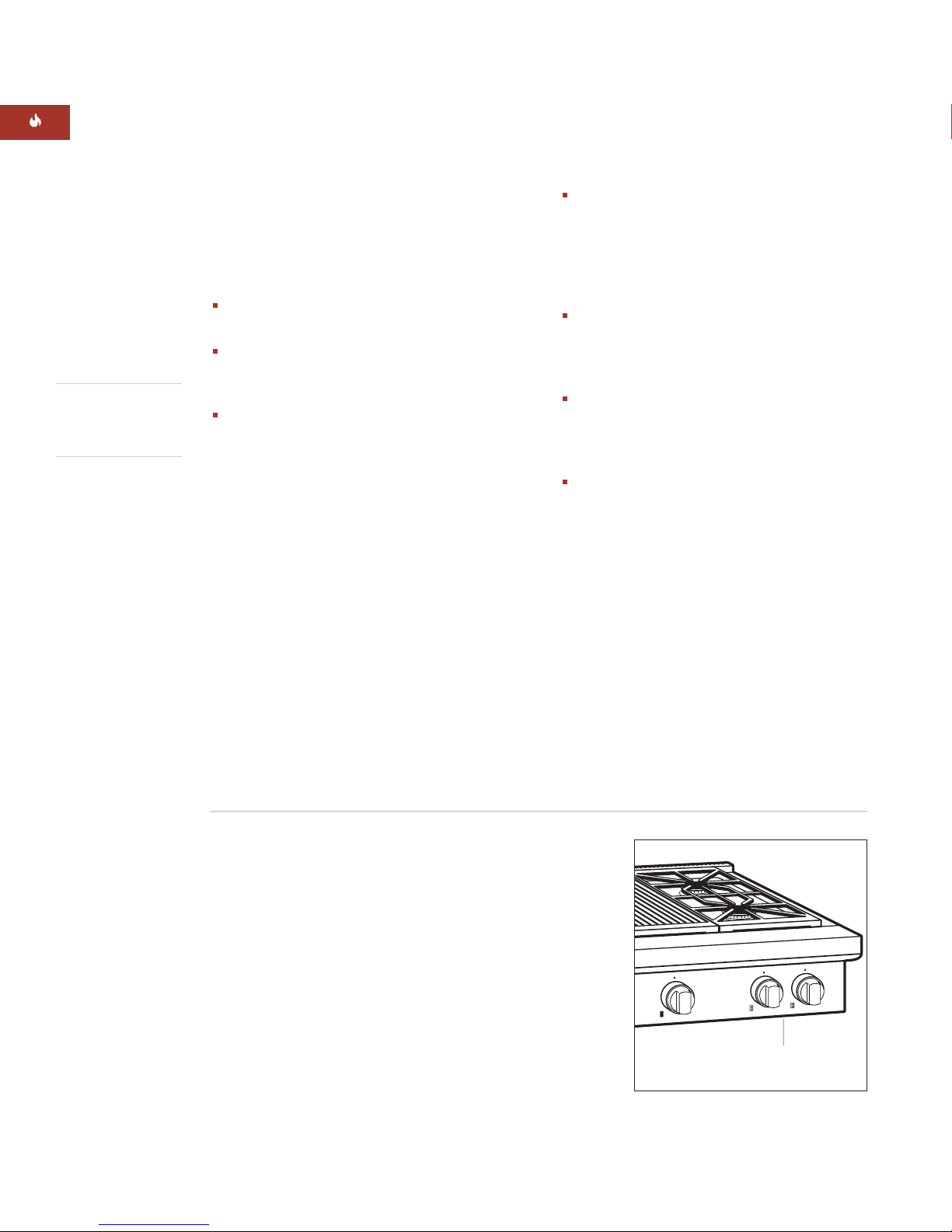
The adjustment conditions for this appliance are stated on the label (or rating
plate). The data plate can be found on the
underside of the sealed rangetop.
Record the model and serial numbers before
installing the sealed rangetop. Both numbers
are listed on the rating plate, located on the
underside of the sealed rangetop. Refer to the
illustration below.
Location of rating plate
under control panel
Rating plate location
6
Page 7

INSTALLATION INSTRUCTIONS
BEFORE YOU START
Check the location where the rangetop will
be installed. The location should be away
from strong draft areas, such as windows,
doors and strong heating vents or fans. Do
not obstruct the flow of air. The area in
which you are installing this appliance must
have an adequate supply of fresh air to
ensure proper combustion and ventilation.
This appliance is not connected to a
combustion products evacuation device.
It shall be installed and connected in accordance with current installation regulations.
Particular attention shall be given to the
relevant requirements regarding ventilation.
All openings in the wall where the rangetop
is to be installed must be sealed.
INSTALLATION SPECIFICATIONS
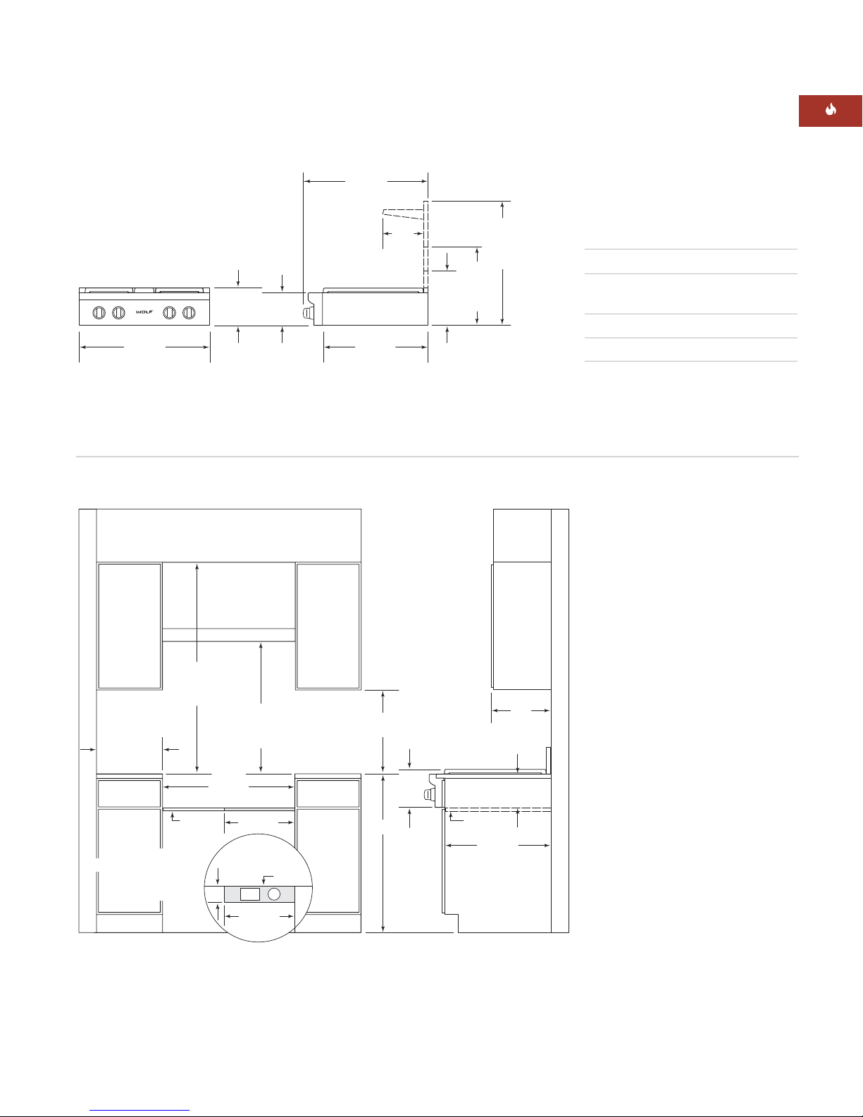
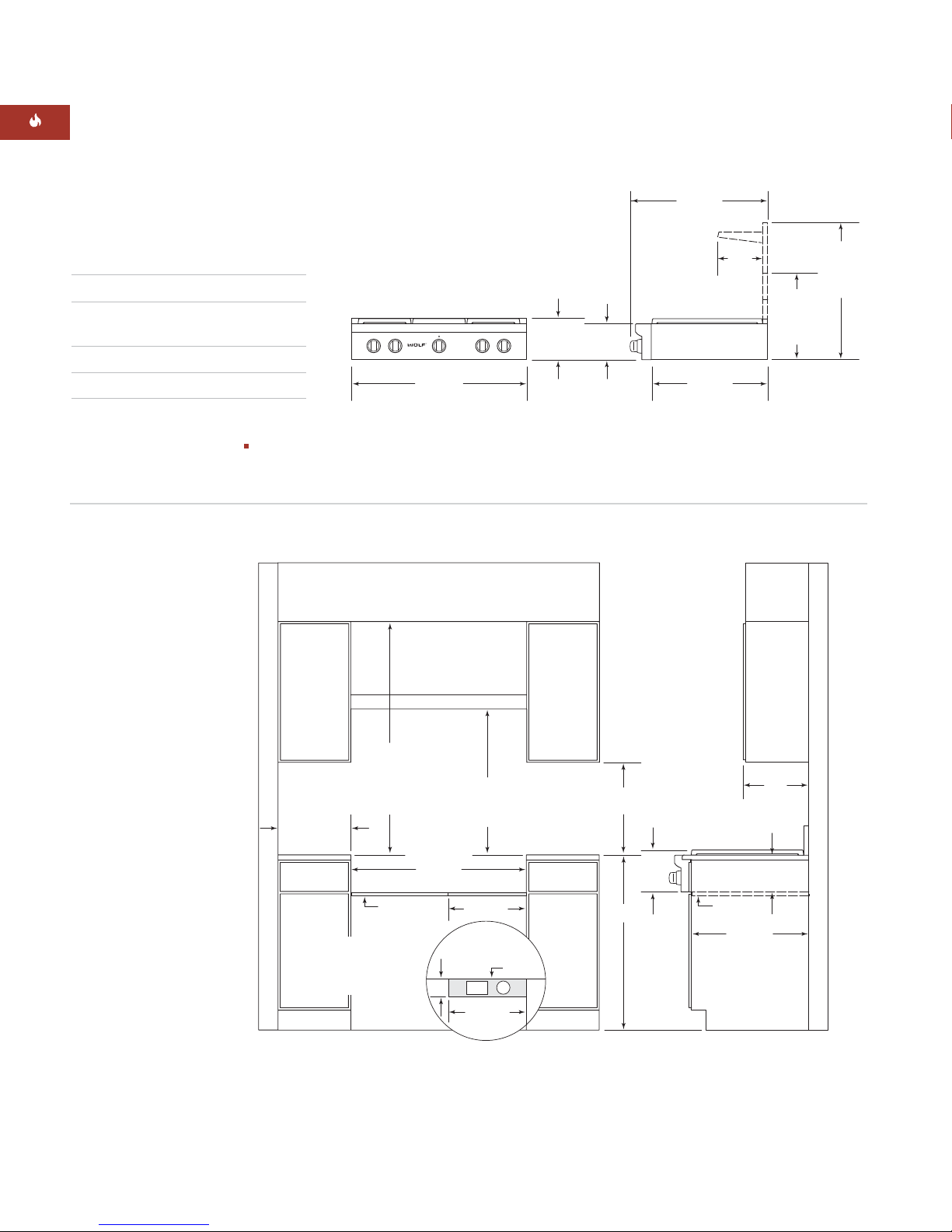
Wolf sealed burner rangetops come in
762 mm, 914 mm and 1219 mm widths. Illustrations on pages 9–11 provide the overall
dimensions and installation specifications for
each width of sealed burner rangetop.
Each rangetop is designed to fit between
cabinets set at the distance specified by the
unit. For example, a 914 mm rangetop will fit a
914 mm opening.
IMPORTANT NOTE:
Cabinet opening dimensions shown in the Installation Specifications
illustrations must be used. These dimensions
provide for required clearances.
IMPORTANT NOTE:
Locate the electrical
supply within dimensions shown in the
Installation Specifications illustrations.
Refer to the Installation Specifications illustration for your model on pages 9–11 for the
exact rough opening dimensions and location
of the gas and electrical supply.
7
Page 8

W OLF SEALED B U RNER RANGET O P
MINIMUM CLEA R ANCES
IMPORTANT NOTE:
Caution must be used
in planning the proper installation of the Wolf
sealed burner rangetop to avoid fire or
damage to adjacent cabinetry or kitchen
equipment. Be sure to follow the minimum
clearances established in the finished rough
opening dimensions.
Refer to the Installation Specifications
illustration for your model on pages 9– 11
for the exact rough opening dimensions.
WA LL I N S TALLATION S
Minimum clearances to combustible
surfaces:
Minimum 457 mm clearance from bottom
of upper cabinet to countertop, within
152 mm minimum side clearance.
Minimum spacing between overhead side
cabinets must be greater than or equal to
the nominal width of the rangetop. The
maximum depth of overhead and side
cabinets is 330 mm, within 152 mm side
clearance.
ISLAN D | P E NINSULA I N S TALLATION S
Minimum clearances to combustible
surfaces:
Island Installations: Minimum 305 mm
clearance to rear wall that rises above the
countertop.
Peninsula Installations: Minimum 152 mm
clearance to side walls and minimum
305 mm clearance to rear wall that rises
above the countertop.
Refer to the Installation Specifications
illustration for your model on pages 9– 11
for the exact rough opening dimensions.
Failure to locate the rangetop without
the proper clearances will result in a fire
hazard.
R I SER REQUIREM E N T S
Installations against a combustible surface:
0 mm clearance for adjacent combustible
materials below the countertop, both sides
and rear.
Bottom of ventilation hood must be
762 mm minimum to 914 mm maximum
from countertop.
Minimum clearances for sealed burner
rangetops without a ventilation hood:
Model ICBSRT304: 762 mm minimum
vertical distance from countertop to
combustible materials above the rangetop.
All Other Sealed Burner Rangetops:
Surface Burners or Griddle (G) Models:
914 mm minimum vertical distance from
countertop to combustible materials above
the rangetop.
Charbroiler (C) Models: 1118 mm minimum
vertical distance from countertop to
combustible materials above the rangetop.
Model ICBSRT304: No riser requirements.
914 mm Sealed Burner Rangetops: A
minimum 254 mm riser is required for all
charbroiler (C) or griddle (G) models
installed against a combustible surface.
1219 mm Sealed Burner Rangetops: A
minimum 254 mm riser is required for all
charbroiler (C) or griddle (G) models
installed against a combustible surface.
VENTILATION
A suuitable ventilation range hood must
be installed.
Important Note: It is recommended that
you operate the Wolf Sealed Burner Rangetop
with a Wolf Pro ventilation hood. Contact your
Wolf dealer for details.
Important Note: When installing a ventilation
hood, refer to the specific requirements of the
hood for the minimum dimension to countertop.
8
Page 9
INSTALLATION INSTRUCTIONS
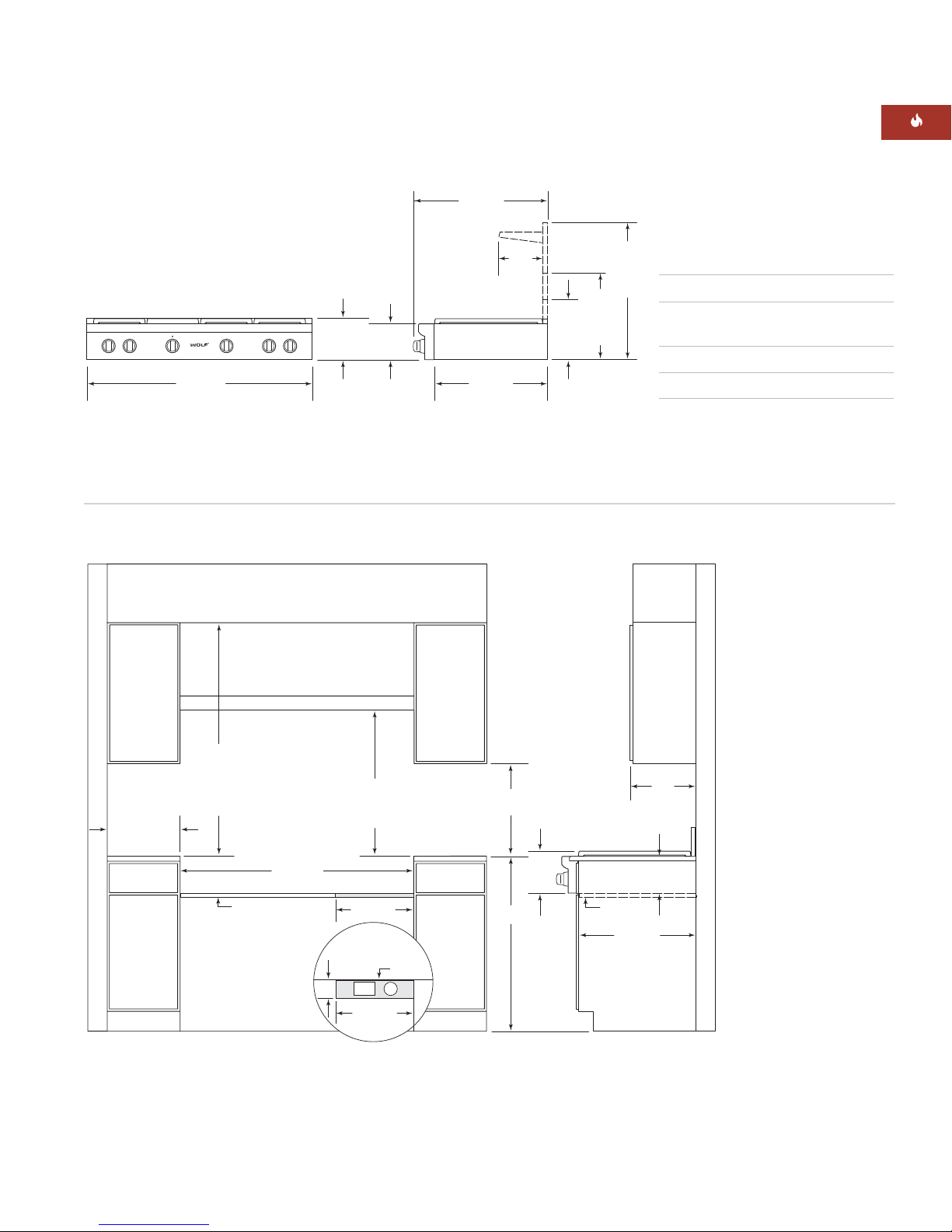
762 mm SEALED BURNER RANGETOP
724 mm
OVERALL DEPTH
COOKING
SURFACE
759 mm
OVERALL WIDTH
216 mm
OVERALL
HEIGHT
191
mm
INSTALLATION SPECIFICATIONS
VENTILATION
HOOD
616 mm
235
mm
318
mm
WITH
127 mm
RISER
445
mm
WITH
254 mm
RISER
699
mm
WITH
508 mm
RISER
OVERALL DIMENSIONS
Overall Width 759 mm
Overall Height
(to cooking surface) 216 mm
Overall Depth 724 mm
Opening Width 762 mm
Dimensions may vary to ±3 mm.
762 mm min
COUNTERTOP
TO COMBUSTIBLE
MATERIALS
152 mm min
TO
COMBUSTIBLE
MATERIALS
(BOTH SIDES)
19 mm
PLATFORM
LOCATION OF GAS AND
ELECTRICAL SUPPLY CUT-OUT
WITHIN SHADED AREA
THROUGH BOTTOM OF
PLATFORM
762 mm min
914 mm max
TO
TO BOTTOM OF
VENTILATION HOOD
762 mm
OPENING WIDTH
406 mm
TOP VIEW
OF PLATFORM
102 mm
E
406 mm
BACK
WALL
G
330 mm
457 mm min
TO COUNTERTOP
COOKING
SURFACE
914 mm
216
mm
19 mm
PLATFORM
191 mm
610 mm
ISLAND INSTALLATIONS: 305 mm MINIMUM
CLEARANCE FROM BACK OF RANGETOP TO
COMBUSTIBLE REAR WALL ABOVE COUNTERTOP–
0 mm TO NON-COMBUSTIBLE MATERIALS
max
Note A:
Side clearances. If the distance
measured from the periphery of the
nearest burner to any vertical surface
is less than 200 mm, the surface shall
be protected in accordance with AS/NZS 5601
Note B:
The rangehood fitted above the
cooktop must be installed according
to the installation instructions for
the rangehood. A minimum
distance of 750 mm is required for a
range hood and 750 mm for an
exhaust fan.
9
Page 10
WOLF SEALED BURNER RANGETOP
VENTILATION HOOD
914 mm
FINISHED ROUGH OPENING WIDTH
762 mm min TO
914 mm max
TO BOTTOM OF
VENTILATION HOOD
914 mm min
COUNTERTOP
TO COMBUSTIBLE
MATERIALS
1118 mm min
FOR CHARBROILER
19 mm
PLATFORM
TOP VIEW
OF PLATFORM
E
G
406 mm
406 mm
102 mm
BACK
WALL
ISLAND INSTALLATIONS: 305 mm MINIMUM
CLEARANCE FROM BACK OF RANGETOP TO
COMBUSTIBLE REAR WALL ABOVE COUNTERTOP–
0 mm TO NON-COMBUSTIBLE MATERIALS
LOCATION OF GAS AND
ELECTRICAL SUPPLY CUT-OUT
WITHIN SHADED AREA
THROUGH BOTTOM OF
PLATFORM
914 mm
457 mm min
TO COUNTERTOP
19 mm
PLATFORM
216
mm
COOKING
SURFACE
191 mm
610 mm
330 mm
max
152 mm min
TO
COMBUSTIBLE
MATERIALS
(BOTH SIDES)
914 mm SEALED BURNER RANGETOP
724 mm
OVERALL DEPTH
OVERALL DIMENSIONS
Overall Width 911 mm
Overall Height
(to cooking surface) 216 mm
Overall Depth 724 mm
Opening Width 914 mm
Dimensions may vary to ±3 mm.
Homeowner:
instructions for future reference and be sure
INSTALLATION SPECIFICATIONS
IMPORTANT NOTE:
A minimum 254 mm
riser is required for
all charbroiler (C) or
griddle (G) models
installed against a
combustible surface.
COOKING
SURFACE
911 mm
OVERALL WIDTH
please read and keep these
216 mm
OVERALL
HEIGHT
191
mm
616 mm
235
mm
445
mm
WITH
254 mm
RISER
699
mm
WITH
508 mm
RISER
Note A:
Side clearances. If the distance
measured from the periphery of the
nearest burner to any vertical surface
is less than 200 mm, the surface shall
be protected in accordance with
AS/NZS 5601
Note: B
The rangehood fitted above the
cooktop must be installed according
to the installation instructions for
the rangehood. A minimum
distance of 750 mm is required for a
range hood and 750 mm for an exhaust fan.
10
Page 11
INSTALLATION INSTRUCTIONS
VENTILATION HOOD
1219 mm
FINISHED ROUGH OPENING WIDTH
762 mm min TO
914 mm max
TO BOTTOM OF
VENTILATION HOOD
914 mm min
COUNTERTOP
TO COMBUSTIBLE
MATERIALS
1118 mm min
FOR CHARBROILER
LOCATION OF GAS AND
ELECTRICAL SUPPLY CUT-OUT
WITHIN SHADED AREA
THROUGH BOTTOM OF
PLATFORM
19 mm PLATFORM
TOP VIEW
OF PLATFORM
E
G
406 mm
406 mm
102 mm
BACK
WALL
ISLAND INSTALLATIONS: 305 mm MINIMUM
CLEARANCE FROM BACK OF RANGETOP TO
COMBUSTIBLE REAR WALL ABOVE COUNTERTOP–
0 mm TO NON-COMBUSTIBLE MATERIALS
914 mm
457 mm min
TO COUNTERTOP
19 mm
PLATFORM
216
mm
COOKING
SURFACE
191 mm
610 mm
330 mm
max
152 mm min
TO
COMBUSTIBLE
MATERIALS
(BOTH SIDES)
1219 mm SEALED BURNER RANGETOP
724 mm
OVERALL DEPTH
COOKING
SURFACE
216 mm
OVERALL
HEIGHT
1216 mm
OVERALL WIDTH
INSTALLATION SPECIFICATIONS
191
mm
616 mm
235
mm
318
mm
WITH
127 mm
RISER
445
mm
WITH
254 mm
RISER
699
mm
OVERALL DIMENSIONS
WITH
508 mm
RISER
Overall Width 1216 mm
Overall Height
(to cooking surface) 216 mm
Overall Depth 724 mm
Opening Width 1219 mm
Dimensions may vary to ±3 mm.
IMPORTANT NOTE:
For 1219 mm sealed
burner rangetops,
a minimum 254 mm
riser is required for
all charbroiler (C) or
griddle (G) models
installed against a
combustible surface.
Note A:
Side clearances. If the distance
measured from the periphery of the
nearest burner to any vertical surface
is less than 200 mm, the surface shall
be protected in accordance with
AS/NZS 5601
Note B:
The rangehood fitted above the
cooktop must be installed according
to the installation instructions for
the rangehood. A minimum
distance of 750 mm is required for a
range hood and 750 mm for an
exhaust fan.
11
Page 12
WOLF SEALED BURNER RANGETOP
IMPORTANT
NOTE
This installation
must conform with
local codes and
ordinances.
INSTALL THE RANGETOP
Prepare the finished rough opening for the
rangetop according to the Installation Specifications illustration for your model on pages
9–11. The platform must be 19 mm thick and
include a cut-out at the right rear for gas
supply and electrical connections.
IMPORTANT NOTE:
The platform must be
level to ensure that the cooking surface is
level.
Remove and discard all packing materials,
including cardboard and tape on the outside of
the rangetop. Remove the burner grates and
styrofoam off the top cooking surface. Be
sure to remove the burner caps packaged in
styrofoam below the burner grates.
If your installation requires a riser, it must be
attached to the rangetop before installation.
Refer to the installation instructions packaged
with the riser.
Position the rangetop on the platform. Gas
supply and electrical connections should be
made before the rangetop is placed in its final
position.
GAS SUPPLY REQUIREMENTS
EXPLOSION HAZARD—
Securely tighten all external gas
connections.
Failure to do so can result in explosion,
fire or death.
IMPORTANT NOTE:
The sealed rangetop must
be connected to a regulated gas supply.
IMPORTANT NOTE:
This installation must
conform with local codes and ordinances.
The rating plate, located on the underside of
the burner box, has information on the type of
gas that should be used. If this information
does not agree with the type of gas available,
check with the local gas supplier.
An ISO 7-1 gas inlet thread is provided on all
units. Please contact your local Wolf dealer if
an ISO 228-1 or other gas inlet thread is
required. Pipe joint compounds, suitable for
use with LP gas should be used. LP gas suppliers usually determine the size and materials
used on the system.
Flexible hose must be certified to AS1869 class B or D
10mm in diameter and no longer than 1200mm long.
The hose must not be kinked or be able to touch any
hot surface. The supply connection point must be
accessible when installed.
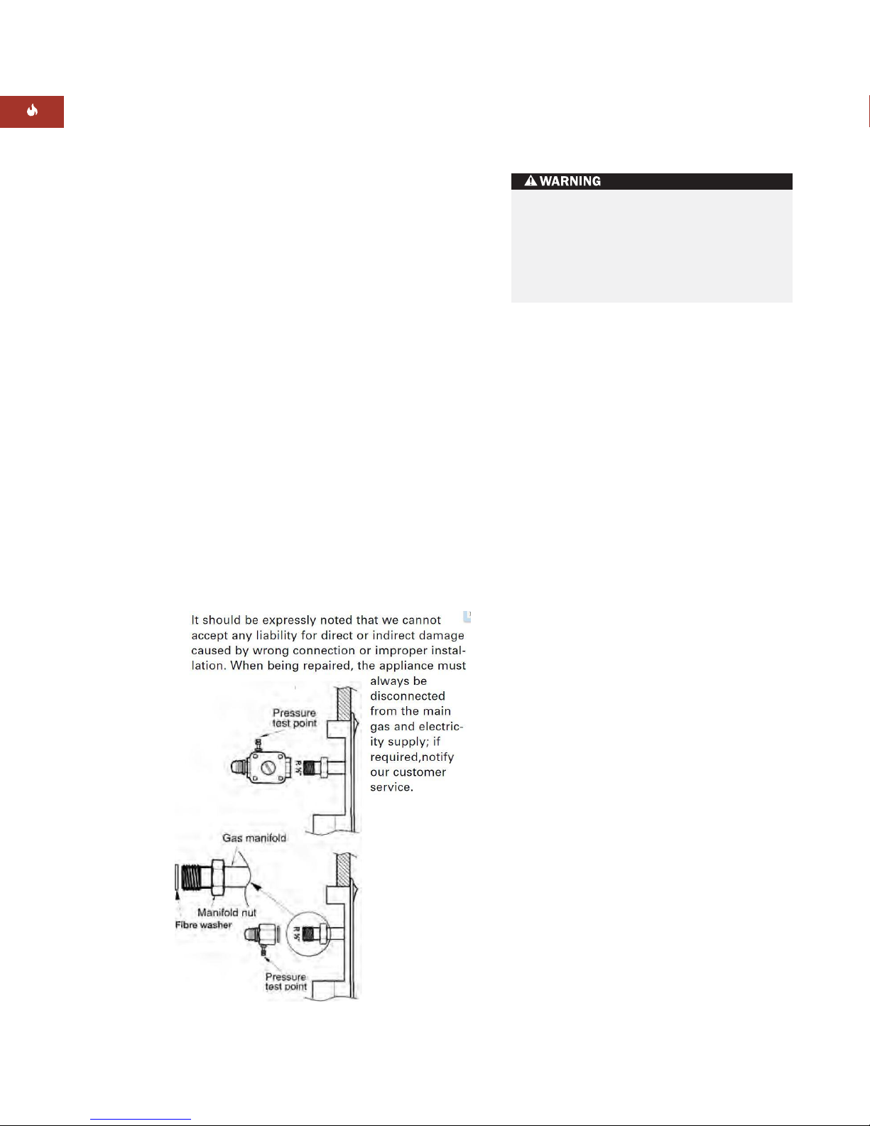
If rigid pipe is used as a gas supply line, a
combination of pipe fittings must be used to
obtain an in-line connection to the sealed
rangetop. All strains must be removed from
the supply and gas lines so the sealed
rangetop will be level and in line.
GAS CONNECTION:
Fit regulator (N.G.) or Propane fitting (LPG), the
direction for gas flow is indicated on the regulator.
Check correct operation of each burner individually
and in combination. Burner flames should be clear
blue, with no yellow tipping. If the burners show any
abnormality, check that the burner heads are
correctly located and refer to trouble shooting page
16. If satisfactory performance can not be obtained
contact Multyflex or the local gas utility.
Note: These burner have no aeration adjustment.
12
Instruct the user in the operation of the appliance
before leaving. A duplicate plate can be attached to
the inside top of an adjacent cupboard.
Page 13
I N S T A L L AT I ON I N S T R U C T I O N S
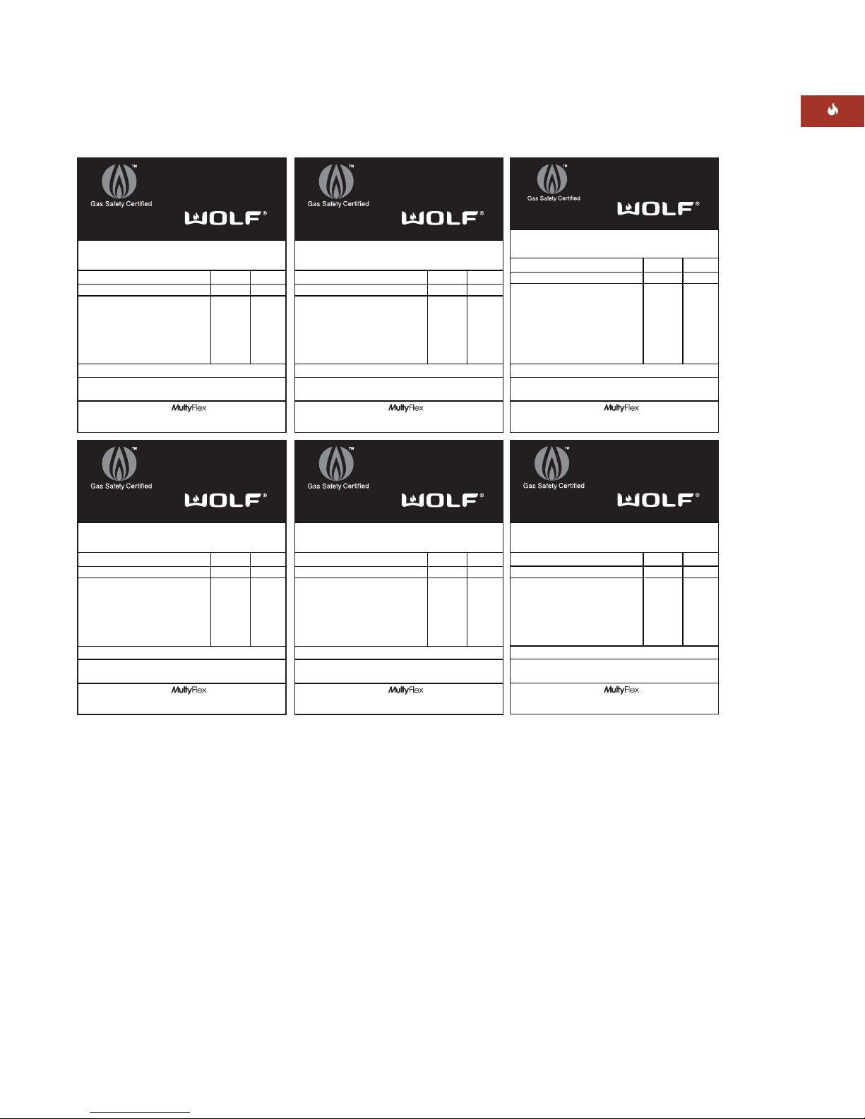
G A S R A T I N G
GSCS20230
SAI GLOBAL
AS4551
Made in USA
Model No: ICBSRT364C
Serial No:
Gas type NG LPG
Test point press. (kPa) 1.0 2.75
Injector sizes (mm)
RHF 1.80 1.09
RHR 1.80 1.09
Grill 1.78 1.09
LHF 1.80 1.09
LHR 1.35 0.89
Total Consumption (MJ/h) 66.0 66.1
Electrical compliance: in accordance with
AS/NZS3100 240 V AC, 10 amps, 50 Hz
Imported & Distributed by
Suite 1/151 Barkley Ave. Burnley VIC 3121
t: +61 3 9421 0232
GSCS20230
SAI GLOBAL
AS4551
Made in USA
Model No: ICBSRT486C
Serial No:
Gas type NG LPG
Test point press. (kPa) 1.0 2.75
Injector sizes (mm)
RHF 1.80 1.09
RHR 1.80 1.09
Grill 1.78 1.09
LHF/CF/CR 1.80 1.09
LHR 1.35 0.89
Total Consumption (MJ/h) 94.0 94.1
Electrical compliance: in accordance with
AS/NZS3100 240 V AC, 10 amps, 50 Hz
Imported & Distributed by
Suite 1/151 Barkley Ave. Burnley VIC 3121
t: +61 3 9421 0232
MF045
GSCS20230
SAI GLOBAL
AS4551
Made in USA
Model No: ICBSRT364G
Serial No:
Gas type NG LPG
Test point press. (kPa) 1.0 2.75
Injector sizes (mm)
RHF 1.80 1.09
RHR 1.80 1.09
Griddle 1.70 1.09
LHF 1.80 1.09
LHR 1.35 0.89
Total Consumption (MJ/h) 66.0 66.1
Electrical compliance: in accordance with
AS/NZS3100 240 V AC, 10 amps, 50 Hz
Imported & Distributed by
Suite 1/151 Barkley Ave. Burnley VIC 3121
t: +61 3 9421 0232
MF048
GSCS20230
SAI GLOBAL
AS4551
Made in USA
Model No: ICBSRT486G
Serial No:
Gas type NG LPG
Test point press. (kPa) 1.0 2.75
Injector sizes (mm)
RHF/CF 1.80 1.09
RHR/CR 1.80 1.09
Griddle 1.70 1.09
LHF 1.80 1.09
LHR 1.35 0.89
Total Consumption (MJ/h) 94.0 94.1
Electrical compliance: in accordance with
AS/NZS3100 240 V AC, 10 amps, 50 Hz
Imported & Distributed by
Suite 1/151 Barkley Ave. Burnley VIC 3121
t: +61 3 9421 0232
MF046
GSCS20230
SAI GLOBAL
AS4551
Made in USA
Model No: ICBSRT484CG
Serial No:
Gas type NG LPG
Test point press. (kPa) 1.0 2.75
Injector sizes (mm)
RHF 1.80 1.09
RHR 1.80 1.09
Grill 1.78 1.09
Griddle 1.70 1.09
LHF 1.80 1.09
LHR 1.35 0.89
Total Consumption (MJ/h) 81.0 81.1
Electrical compliance: in accordance with
AS/NZS3100 240 V AC, 10 amps, 50 Hz
Imported & Distributed by
Suite 1/151 Barkley Ave. Burnley VIC 3121
t: +61 3 9421 0232
MF049
GSCS20230
SAI GLOBAL
AS4551
Made in USA
Model No: ICBSRT484F
Serial No:
Gas type NG LPG
Test point press. (kPa) 1.0 2.75
Injector sizes (mm)
RHF 1.80 1.09
RHR 1.80 1.09
French Top 1.80 1.09
LHF 1.80 1.09
LHR 1.35 0.89
Total Consumption (MJ/h) 65.0 65.1
Electrical compliance: in accordance with
AS/NZS3100 240 V AC, 10 amps, 50 Hz
Imported & Distributed by
Suite 1/151 Barkley Ave. Burnley VIC 3121
t: +61 3 9421 0232
MF047
MF050
13
Page 14

WOLF SEALED BURNER RANGETOP
GAS SUPPLY REQUIREMENTS
GAS LEAK TESTING
Use a brush and liquid detergent to test all gas
connections for leaks. Bubbles around connections will indicate a leak. If a leak appears, shut
off the gas valve and adjust connections. Then
check connections again. Clean all the detergent solution from the rangetop.
Never test for a gas leak with a match or
other flame.
14
Page 15

INSTALLATION INSTRUCTIONS
ELECTRICAL REQUIREMENTS
RECOMMENDED GROUND METHOD
ELECTRICAL SHOCK HAZARD—
Plug into a grounded 3-prong adapter.
Do not remove ground prong.
Do not use an adapter.
Failure to follow these instructions can
result in electric shock, fire or death.
IMPORTANT NOTE:
If codes permit and a
separate ground wire is used, it is recommended that a qualified electrician determine
that the ground path is adequate.
IMPORTANT NOTE:
Check with a qualified
electrician if you are not sure whether the
sealed rangetop is properly grounded.
IMPORTANT NOTE:
Do not ground to a gas
pipe.
A 220-240 VAC, 50/60 Hz, fused electrical
supply is required. A time-delay fuse or circuit
breaker is recommended. It is recommended
that a separate circuit serving only this appliance be provided.
IMPORTANT NOTE:
For your personal safety,
this sealed rangetop must be grounded. This
sealed rangetop is equipped with a 3-prong
ground plug. To minimize possible shock
hazard, the cord must be plugged into a
mating 3-prong ground-type outlet, grounded
in conformance with all local codes and ordinances. If a mating outlet is not available, it is
the obligation of the customer to have a
properly grounded, 3-prong outlet installed by
a qualified electrician.
IMPORTANT NOTE:
If product is connected to
a GFCI protected outlet, nuisance tripping of
power supply may occur, resulting in loss of
product operation.
WIRING DIAGRAM
The wiring diagram covering the electrical
circuit is located on the inside left wall of the
rangetop.
Electronic ignition systems operate within
wide voltage limits, but proper ground and
polarity are necessary. In addition to checking
that the outlet provides 220-240 VAC power
and is correctly grounded, the outlet must be
checked by a qualified electrician to see if it is
wired with correct polarity.
This appliance, when installed, must be electrically grounded in accordance with local codes.
15
Page 16

WOLF SEALED BURNER RANGETOP
SURFACE BURNERS
INITIAL LIGHTING
The surface burners use electronic igniters in
place of standing pilots. When the sealed
rangetop control knob is pushed in and turned
to the position, the system creates a spark
to light the burner. This sparking continues
until the electronic ignition senses a flame. If
the burner fails to ignite after 10 seconds,
return the knob to the position and attempt
to ignite by turning the knob back to the
position.
Be sure to place the burner heads and caps on
each burner base and position the burner
grates over the burner bases and heads before
lighting.
To check operation of the surface burners,
push in and turn each control knob to the
position. The flame should light within four
seconds.
If the burners do not light properly, turn
control knob to the position. Check that the
burner heads and caps are in the proper
position. Check that the power supply cord is
plugged in and that the circuit breaker or
house fuse has not blown. Check operation
again, if the burners do not light properly at
this point, contact a Wolf authorized service
center.
IMPORTANT NOTE:
Initial lighting of the
surface burners may take slightly longer, as air
in the system must be purged before gas can
be supplied to the burner.
SEALED RANGETOP REMOVAL
If it is necessary to remove the sealed
rangetop for cleaning or service, shut off the
gas supply. Disconnect the gas and electric
supply. Remove the mounting brackets on the
right and left side of the burner box and
remove the sealed rangetop. Reinstall in the
reverse order and check the gas connection for
leaks.
TROUBLESHOOTING
IMPORTANT NOTE:
If the sealed rangetop
does not operate properly, follow these troubleshooting steps:
Verify that power is being supplied to the
sealed rangetop.
Check that gas valves are turned to the ON
position.
Check the gas supply and electrical
connections to ensure that the installation
has been completed correctly.
Follow troubleshooting procedures as
described in the Wolf Sealed Burner
Rangetops Use & Care Information.
If the sealed rangetop still does not work,
contact a Wolf authorized service center. Do
not attempt to repair the sealed rangetop
yourself. Wolf is not responsible for service
required to correct a faulty installation.
16
Page 17

INSTALLATION INSTRUCTIONS
IF YOU NEED SERVICE
For service in your area, contact either your
Wolf dealer or visit the Showroom Locator
section of our website, wolfappliance.com
to find the regional distributor by country.
When calling for service, you will need the
sealed rangetop model and serial numbers.
Both numbers are listed on the rating plate,
located on the underside of the sealed
rangetop. Refer to the illustration on page 6
for location of the rating plate.
CONTACT
INFORMATION
Website:
wolfappliance.com
The information and images in this book are the
copyright property of Wolf Appliance, Inc., an
affiliate of Sub-Zero, Inc. Neither this book nor any
information or images contained herein may be
copied or used in whole or in part without the
express written permission of Wolf Appliance,
Inc.,an affiliate of Sub-Zero, Inc.
©Wolf Appliance, Inc. all rights reserved.
17
Page 18
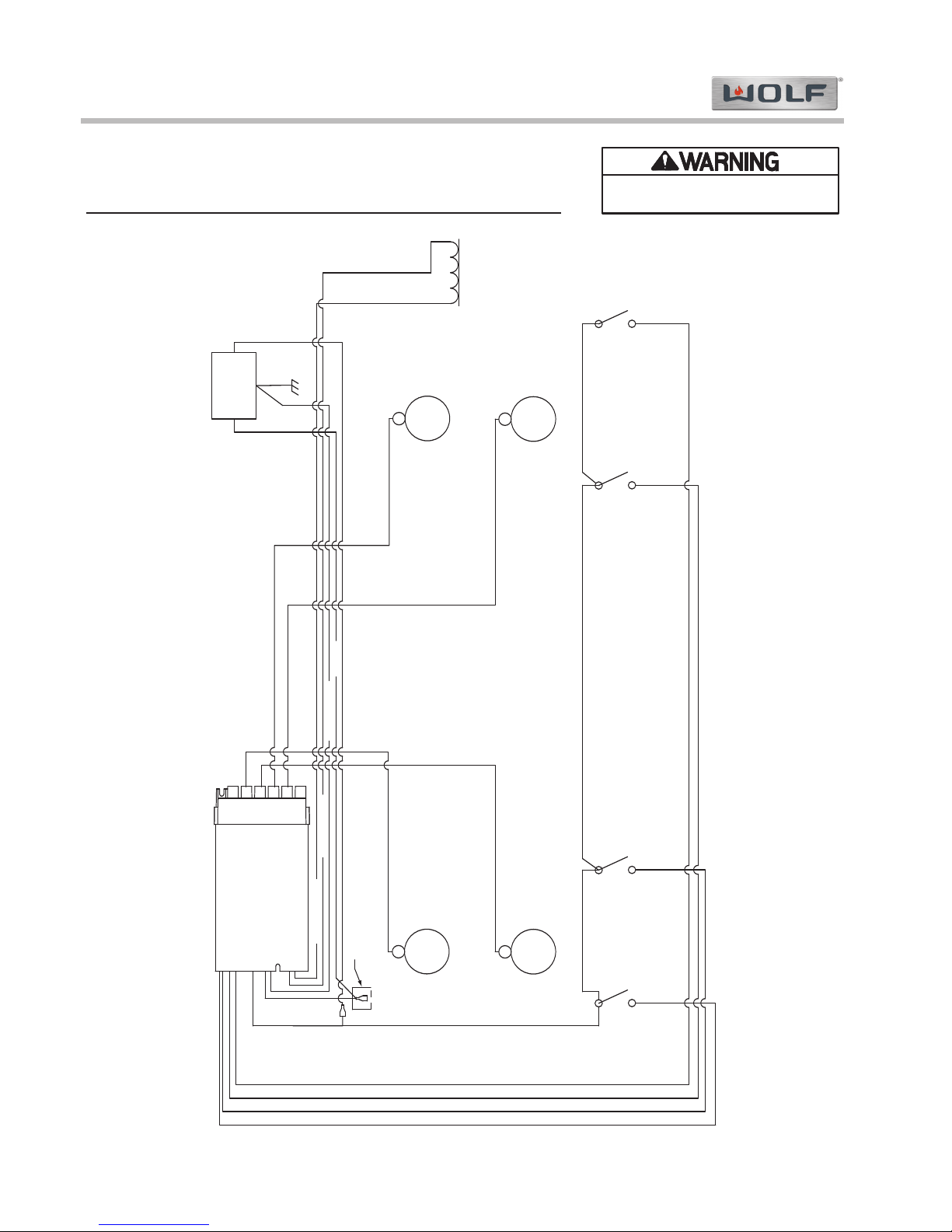
ICB Sealed Burner Rangetop (ICBSRT) Series
ICB Sealed Burner Rangetop (ICBSRT) Series
Wiring Diagrams
7-2
#820376 - Revision A - October, 2011
SW1
SW2
SW3
SW4
SW5
SW6
LINE
NOT USED
NEUTRAL
GND
GAS VALVE
NOT USED
NOT USED
GAS VALVE
S1
S2
S3
S4
CNTRL, IGNTR,
VALVE 4 PT
LEFT REAR
S1
LEFT FRONT
S2
RIGHT REAR
S3
RIGHT FRONT
S4
LEFT REAR
SWITCH SW1
LEFT FRONT
SWITCH SW2
RIGHT FRONT
SWITCH SW4
RIGHT REAR
SWITCH SW3
10 VDC SOLENOID
SPARKER WIRE
SPARKER WIRE
SPARKER WIRE
SPARKER WIRE
3-GRN/YLW
4-GRN/YLW
2-WHT
1-BLACK
6-ORANGE
7-ORANGE
14-BLACK
8-BLUE
9-BLUE
10-BLUE
11-BLUE
5-WHITE
15-BLACK
16-BLACK 17-BLACK
18-BLACK
CAPPED CONNECTOR
GROUND
N IN L1 IN
230V 50 CYCLES
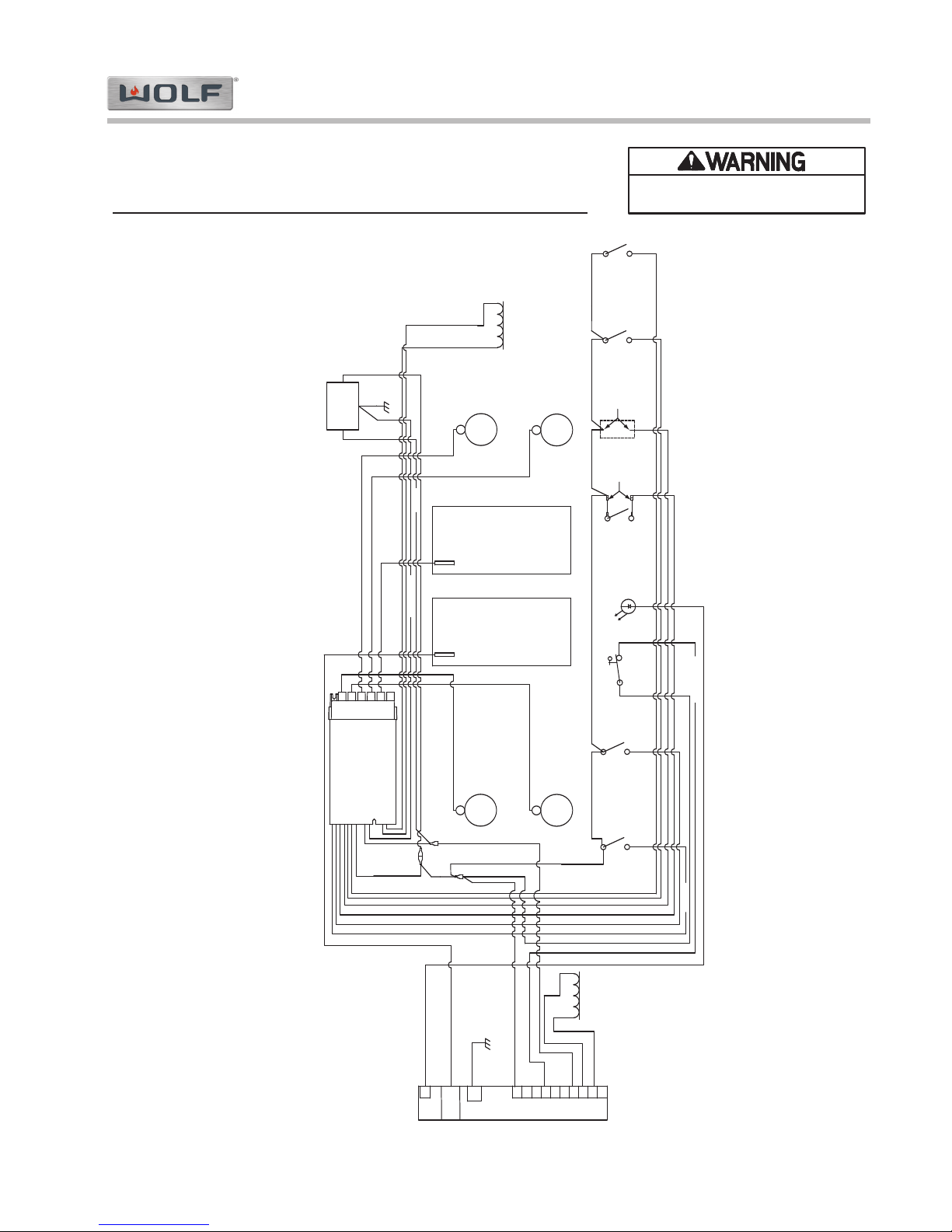
WIRING SCHEMATIC Model: ICBSRT304
- This wiring information is provided for use by qualified service personnel only.
- Disconnect appliance from electrical supply before beginning service.
- Be sure all grounding devices are connected when service is complete.
- Failure to observe the above warnings may result in severe electrical shock.
Page 19
Wiring Diagrams
ICB Sealed Burner Rangetop (ICBSRT) Series
ICB Sealed Burner Rangetop (ICBSRT) Series
7-7
#820376 - Revision A - October, 2011
2-WHT
1-BLK
8-BLUE
9-BLUE
29-BLK
26-BLK/ORN
GRIDDLE
THERMOSTAT
2 VDC
INDICATOR
LED
RIGHT REAR
SWITCH
SW3
11-BLUE
RIGHT FRONT
SWITCH
SW4
21-BLK
10 VDC
SOLENOID
7-ORN
230 V
50 CYCLES
N IN L1 IN
GROUND
3-GRN/YEL
6-ORN
RIGHT
FRONT
S4
RIGHT
REAR
S3
GRIDDLE
DIRECT
SPARK IGNITOR
MODULE
4-GRN/YEL
NOT USED
CONTROL, IGNTR,
VALVE 5 PT
NOT USED
GAS VALVE
GAS VALVE
GND
NEUTRAL
NOT USED
LINE
SW6
SW4
SW5
SW3
SW2
SW1
S5S4S3
S2
S1
SPARKER WIRE
18-BLK
SPARKER WIRE
LEFT
REAR
S1
SPARKER WIRE
LEFT FRONT
SWITCH
SW2
17-BLK
LEFT
FRONT
S2
LFT REAR
SWITCH
SW1
16-BLK
5-WHT
14-BLK
15-BLK
27-GRN/YEL
28-BLK
25-WHT
24-ORN
10 VDC
SOLENOID
23-ORN
123456789
10
GND
SPARK1
J4
SPARKER WIRE
CHARBROILER
S5
SPARKER WIRE
SPARKER WIRE
DIRECT SPARK
IGNITOR MODULE
CHARBRLR
SWITCH
SW5
13-BLUE
19-BLK
20-BLK
10-BLUE
CAPPER
CONNECTORS
12-BLUE
JUMPER
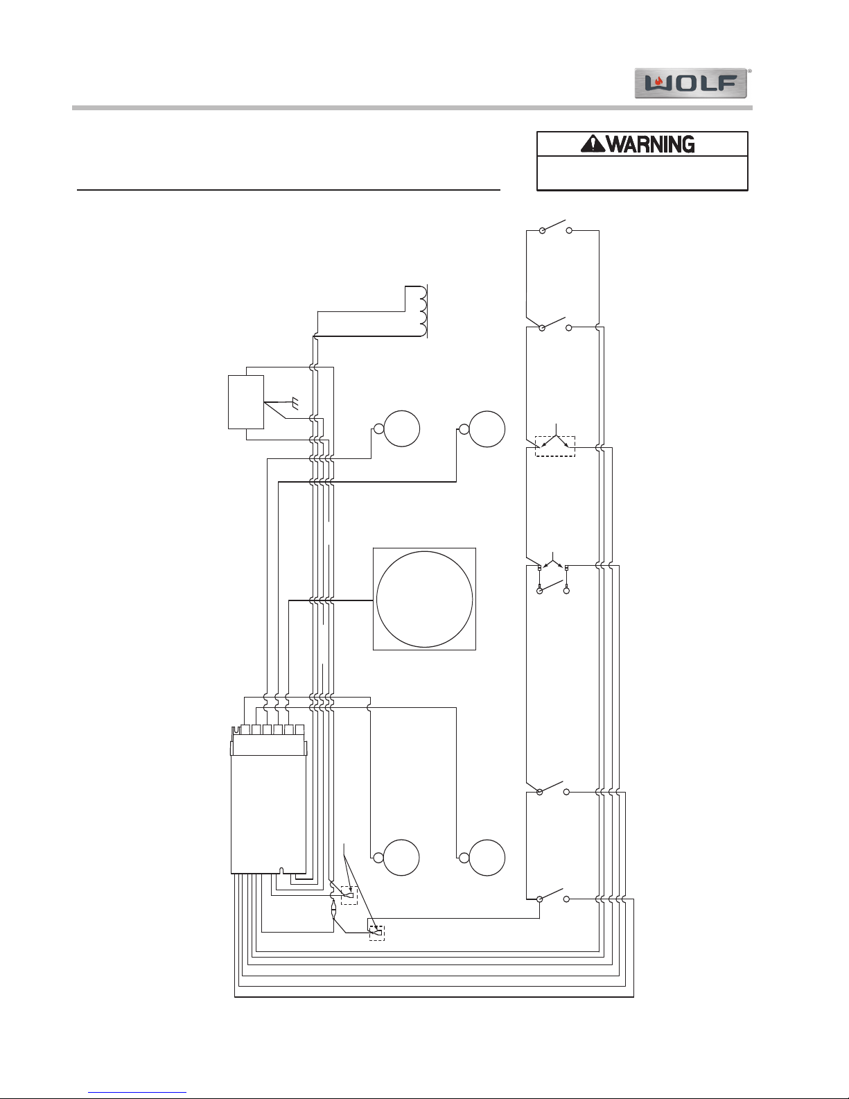
WIRING SCHEMATIC Model: ICBSRT484CG
- This wiring information is provided for use by qualified service personnel only.
- Disconnect appliance from electrical supply before beginning service.
- Be sure all grounding devices are connected when service is complete.
- Failure to observe the above warnings may result in severe electrical shock.
Page 20
ICB Sealed Burner Rangetop (ICBSRT) Series
ICB Sealed Burner Rangetop (ICBSRT) Series
Wiring Diagrams
7-8
#820376 - Revision A - October, 2011
NOT USED
NOT USED
GAS VALVE
GAS VALVE
GND
NEUTRAL
NOT USED
LINE
SW6
SW4
SW5
SW3
SW2
SW1
S5
S4
S3
S2
S1
17-BLK
16-BLK
8-BLUE
9-BLUE
FRENCHTOP
SWITCH
SW5
12-BLUE
13-BLUE
19-BLK
20-BLK
RIGHT REAR
SWITCH
SW3
10-BLUE
11-BLUE
RIGHT FRONT
SWITCH
SW4
21-BLK
10 VDC
SOLENOID
7-ORN
230 V
50 CYCLES
N IN L1 IN
GROUND
3-GRN/YEL
6-ORN
RIGHT
FRONT
S4
RIGHT
REAR
S3
1-BLK
2-WHT
FRENCHTOP
S5
4-GRN/YEL
CONTROL, IGNTR,
VALVE 5 PT
SPARKER WIRE
18-BLK
SPARKER WIRE
LEFT
REAR
S1
SPARKER WIRE
LEFT FRONT
SWITCH
SW2
LEFT
FRONT
S2
LEFT REAR
SWITCH
SW1
5-WHT
14-BLK
15-BLK
SPARKER WIRE
SPARKER WIRE
JUMPER
CAPPER
CONNECTORS
CAPPER CONNECTORS
WIRING SCHEMATIC Model: ICBSRT484F
- This wiring information is provided for use by qualified service personnel only.
- Disconnect appliance from electrical supply before beginning service.
- Be sure all grounding devices are connected when service is complete.
- Failure to observe the above warnings may result in severe electrical shock.
Page 21

Page 22

WOLF APPLIANCE, INC.
P O BOX 44848
MADISON, WI 53744 USA
WOLFAPPLIANCE.COM
M F 051 0 7/2012
Australian Distributor of Sub-Zero & Wolf
1/151 Barkly Avenue, Burnley Victoria Australia 3121
Telephone. +61 3 9421 0232 Facsimile. +61 3 9421 0242
www.subzerowolf.com.au
74
 Loading...