

WOLF ICBCSO24TESTH, ICBCSO30PESPH1, ICBCSO30TESTH1, ICBCSO30CMBTH1, ICBCSO30PMSPH1 Installation Guide
...Page 1

CONVECTION STEAM OVENS
INSTALLATION GUIDE
GUÍA DE INSTALACIÓN
GUIDE D’INSTALLATION
GUIDA ALL’INSTALLAZIONE
INSTALLATIONSANLEITUNG
Page 2

CONVECTION STEAM OVENS
SPECIFICATIONS
Contents
2 Convection Steam Ovens
2 Specications
4 Installation
5 Troubleshooting
Features and specications are subject to change at any
time without notice. Visit wolfappliance.com/specs for the
most up-to-date information.
Important Note
To ensure this product is installed and operated as safely
and efciently as possible, take note of the following types
of highlighted information throughout this guide:
IMPORTANT NOTE highlights information that is especially
important.
CAUTION indicates a situation where minor injury or product
damage may occur if instructions are not followed.
WARNING states a hazard that may cause serious injury or
death if precautions are not followed.
IMPORTANT NOTE: Save these instructions for the local
electrical inspector.
Product Information
Important product information including the model and
serial number are listed on the product rating plate. The
rating plate is located on the left side of the front face frame.
The oven door must be open to view the rating plate. Refer
to the illustration below.
If service is necessary, contact Wolf factory certied service
with the model and serial number.
RATING PLATE
Rating plate location.
Installation Requirements
The convection steam oven can be installed in a standard or
ush inset application. A minimum base support of 45 kg is
required. The electrical supply for the oven must be located
in an adjacent cabinet.
For standard installations, face trim will overlap stiles and
rails. Refer to the chart below for trim overlaps.
For ush inset installations, a minimum 3 mm reveal is
required on all four sides. To ensure consistent reveals, each
corner of the opening must be exactly 90°. Finish the edges
of the opening. They may be visible when the door is open.
If the convection steam oven is installed above or below a
Wolf E series oven in a ush inset application, a 6 mm reveal
is required.
TRIM OVERLAP
OVERLAP 610 mm MODEL 762 mm MODEL
Top 5 mm 5 mm
Bottom 0 mm 0 mm
Sides 18 mm 98 mm
2 | English
Page 3

SPECIFICATIONS
SIDE
Electrical supply must be located in adjacent cabinet within .9 m of opening.
Dashed line represents profile of unit.
Electrical
Installation must comply with all applicable electrical codes
and be properly grounded (earthed).
The electrical supply for the convection steam oven must
be placed in an adjacent cabinet within reach of the 1.8 m
power cord. Locate the electrical supply as shown in the
illustrations on pages 3–4. A separate circuit, servicing only
this appliance is required. A ground fault circuit interrupter
(GFCI) is not recommended and may cause interruption of
operation.
Performance may be compromised if the electrical supply is
less than 220 volts.
RATING PLATE
Rating plate location.
ELECTRICAL REQUIREMENTS
Electrical Supply 220-240 VAC, 50 Hz
Service 3700 Watts
Power Cord 2.5 m
380-415 VAC 2N, 50 Hz
IMPORTANT NOTE: Connection of this appliance should be
through a fused connection unit or a suitable isolator, which
complies with national and local safety regulations. The
on/off switch should be easily accessible after the appliance has been installed. If the switch is not accessible after
installation (depending on country) an additional means of
disconnection must be provided for all poles of the power
supply. When switched off there must be an all pole contact
gap of 3 mm in the isolator switch. This 3 mm contact disconnect gap must apply to any isolator switch, fuses and/or
relays according to EN60335.
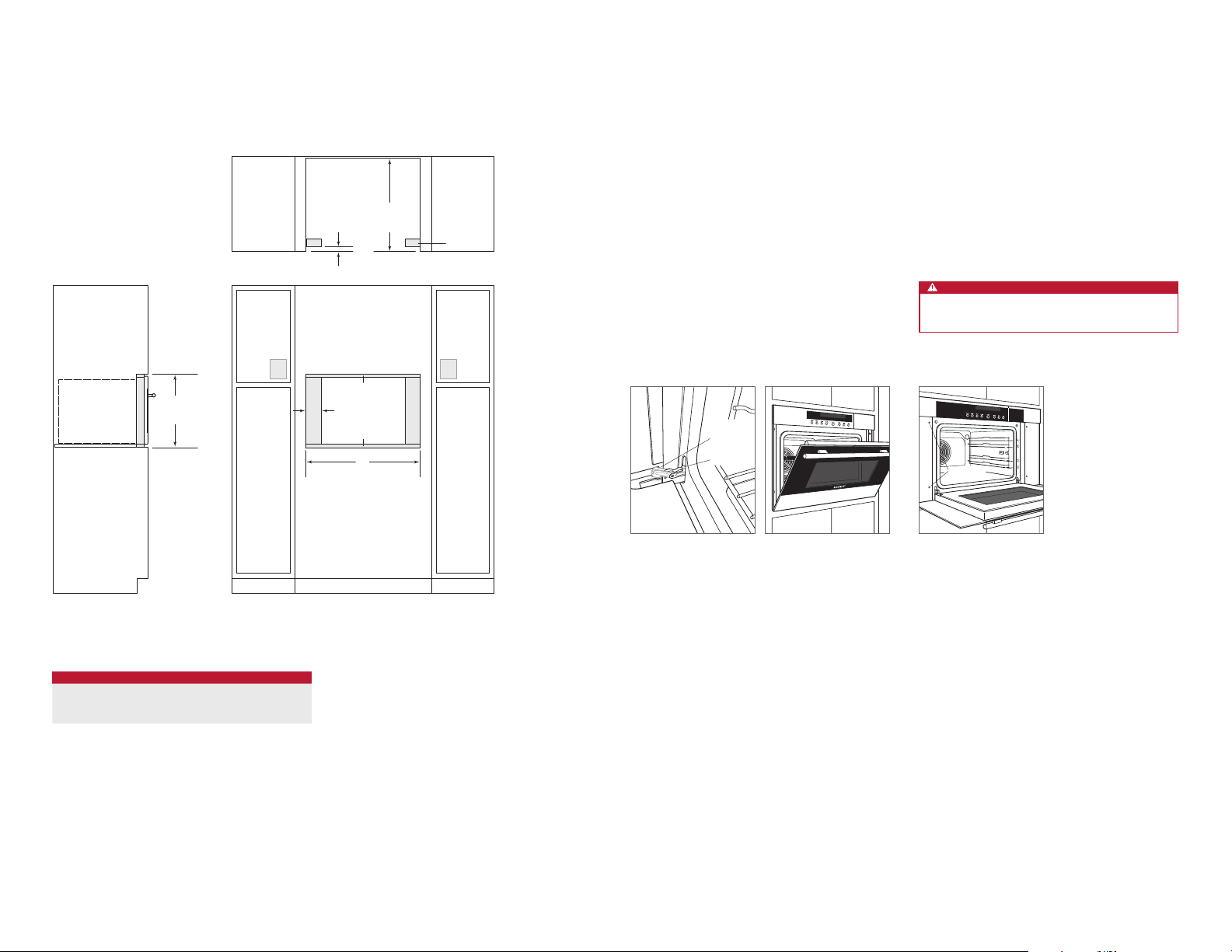
Convection Steam Oven
STANDARD INSTALLATION
449 mm
OPENING
HEIGHT
548 mm
OPENING
DEPTH
TOP VIEW
W
OPENING WIDTH
EE
VIEW
OPENING WIDTH
MODEL W
610 mm Model 562 mm
762 mm Model 562 mm
FRONT VIEW
wolfappliance.com | 3
Page 4
SPECIFICATIONS
INSTALLATION
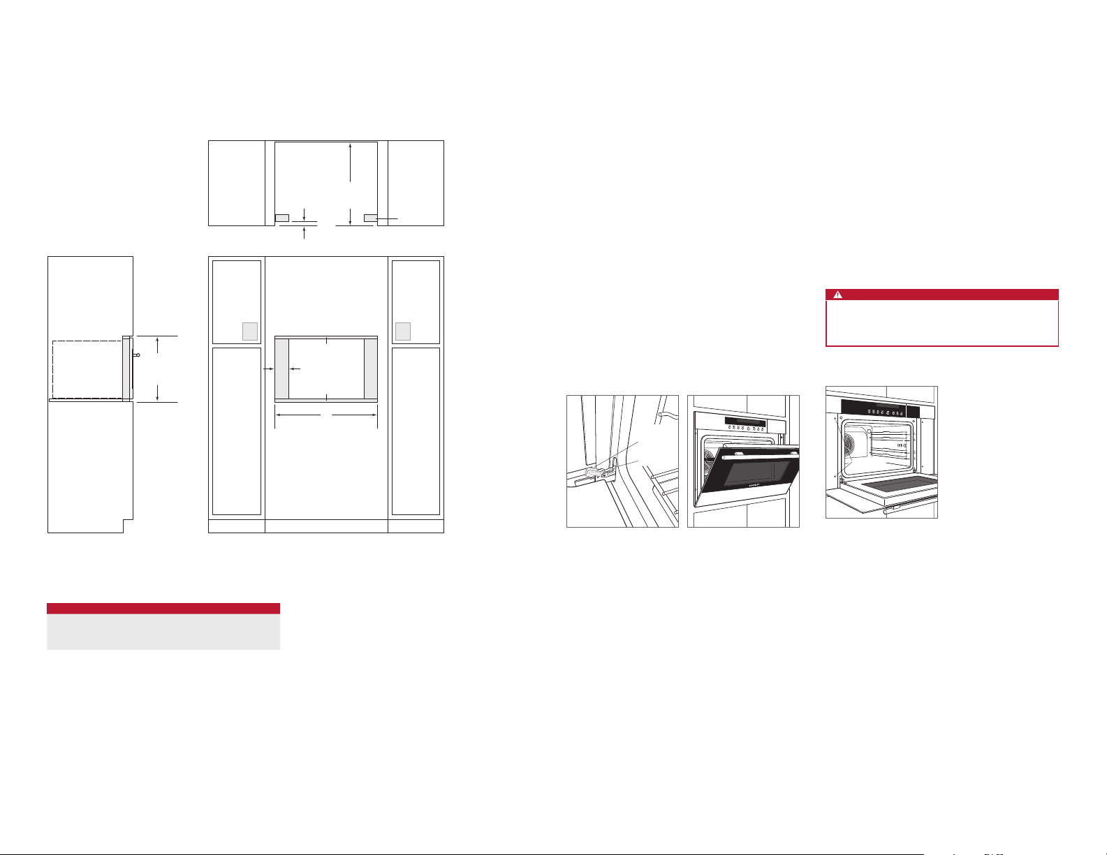
Convection Steam Oven
FLUSH INSET INSTALLATION
460 mm
FLUSH INSET
HEIGHT
25 mm
FLUSH INSET
TOP VIEW
584 mm
DEPTH
FINISHED
CLEATS*
Preparation
Before moving the oven, protect any nished ooring and
secure oven door closed to prevent damage.
Use an appliance dolly to move the unit near the opening.
Remove and recycle packing materials. Do not lift or carry
the oven by the door handle.
OVEN DOOR REMOVAL
To remove, open oven door completely. Rotate both hinge
latches forward to the open position. Close door to the
“at-rest” position, then lift up and out. Refer to the illustrations below.
To reinstall, insert door hinges into frame openings. Open
oven door completely and rotate both hinge latches back to
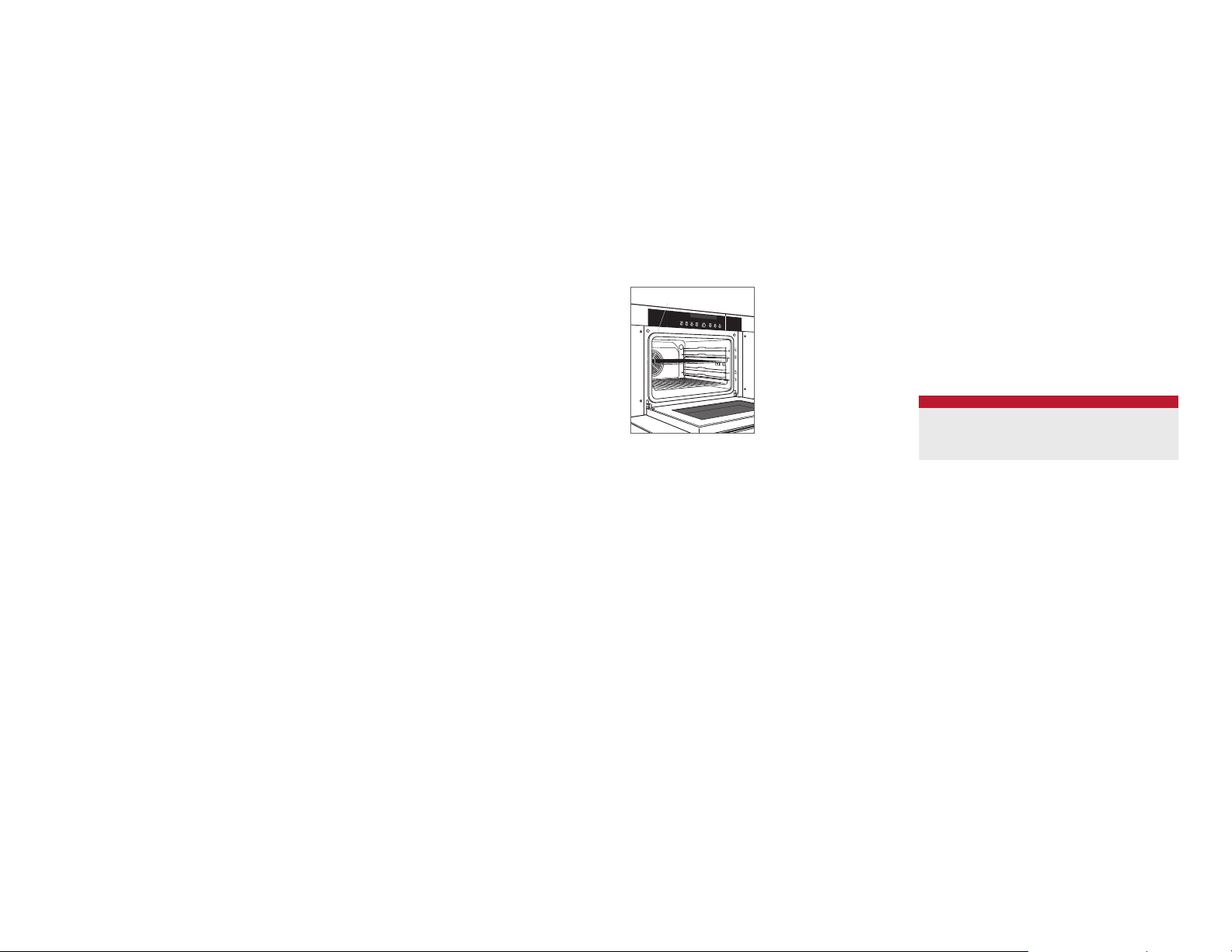
Installation
Place the oven in the opening and slide back partially. Guide
the power cord through the opening of the adjacent cabinet
and slide oven back fully. Verify the power cord is not
trapped between the oven and cabinet wall.
Locate mounting holes on the oven side trim, two on each
side. Drill pilot holes. Use the mounting screws provided to
secure the oven to cabinetry. Refer to the illustration below.
To avoid interference, a 90° door stop may be required for
any appliance or cabinet door installed next to the oven.
CAUTION
Failure to install the mounting screws may cause the
oven to tip forward during use.
the closed position.
EE
A
FLUSH INSET WIDTH
8 mm
3 mm
W
Oven door hinge latch.
OPEN
POSITION
CLOSED
POSITION
Door “at-rest” position.
MOUNTING
HOLES
Oven installation.
*Will be visible and should be finished to match cabinetry.
NOTE: Electrical supply must be located in adjacent cabinet within .9 m of opening.
Dashed line represents profile of unit.
OPENING WIDTH
MODEL W A
610 mm Model 603 mm 21 mm
762 mm Model 765 mm 102 mm
4 | English
FRONT VIEWSIDE VIEW
Page 5

TROUBLESHOOTING
Troubleshooting
IMPORTANT NOTE: If the convection steam oven does not
operate properly, follow these troubleshooting steps:
• Verify electrical power is supplied to the oven.
• Verify proper electrical connections.
• If the oven does not operate properly, contact Wolf
factory certied service. Do not attempt to repair the
oven. Wolf is not responsible for service required to
correct a faulty installation.
Wolf, Wolf & Design, Wolf Gourmet, W & Design and the color red as applied to knobs are registered trademarks and service marks of Wolf Appliance, Inc. Sub-Zero, Sub-Zero & Design, Dual Refrigeration, Constant Care, The Living Kitchen, Great American Kitchens The Fine Art of Kitchen Design, and Ingredients are registered trademarks and service marks of Sub-Zero,
Inc. (collectively, the “Company Marks.”) All other trademarks or registered trademarks are property of their respective owners in the United States and other countries.
wolfappliance.com | 5
Page 6
HORNOS DE CONVECCIÓN CON VAPOR
ESPECIFICACIONES
Índice
2 Hornos de convección con vapor
2 Especicaciones
4 Instalación
5 Localización y solución de problemas
Las características y especicaciones están sujetas a cambios sin previo aviso. Visite wolfappliance.com/specs para
obtener la información más actualizada.
Nota importante:
Para garantizar que este producto se instala y funciona de
la forma más ecaz y segura posible, tenga en cuenta la
información que se especica en esta guía:
Cuando aparece
que resulta especialmente importante.
PRECAUCIÓN indica una situación en la que se pueden
sufrir heridas leves o provocar daños al producto si no se
siguen las instrucciones.
AVISO indica peligro de que se produzcan heridas graves o
incluso la muerte si no se respetan las precauciones.
NOTA IMPORTANTE: Conserve estas instrucciones para el
inspector eléctrico local.
NOTA IMPORTANTE, se resalta información
Información sobre el producto
En la placa de datos del producto encontrará información
importante, incluyendo el modelo y el número de serie. La
placa de datos está ubicada en el lado izquierdo del marco
frontal. La puerta del horno debe estar abierta para ver la
placa de datos. Consulte la siguiente ilustración.
Si necesita recurrir a un servicio técnico, póngase en contacto con un servicio de Wolf certicado y especique el
modelo y el número de serie.
PLACA DE DATOS
Ubicación de la placa de datos.
Requisitos de instalación
El horno de convección con vapor puede instalarse en una
aplicación estándar o empotrable. Se requiere un soporte
de base que aguante un peso de 45 kg. mínimo. El suministro eléctrico para el horno de convección con vapor debe
estar ubicado en un mueble contiguo.
Para instalaciones estándar, el contramarco frontal irá
superpuesto sobre los raíles y montantes. Observe la
siguiente tabla para ver las superposiciones del marco.
Para instalaciones empotrables, es necesario dejar un
margen mínimo de 3 mm en los cuatro lados. Para garantizar unos márgenes consistentes, cada esquina de la
cavidad debe tener exactamente 90º. Remate los bordes
de la cavidad, ya que son áreas que pueden resultar muy
visibles al abrir la puerta.
Si el horno de convección con vapor se instala encima o
debajo de un horno Wolf de la Serie E en una aplicación
empotrable, es necesario utilizar un margen de 6 mm.
SUPERPOSICIÓN DEL MARCO
SUPERPOSICIÓN 610 mm MODELO 762 mm MODELO
Superior 5 mm 5 mm
Inferior 0 mm 0 mm
Lados 18 mm 98 mm
2 | Español
Page 7

ESPECIFICACIONES
VIST
El suministro eléctrico debe estar ubicado en un armario contiguo a 0,9 m de la cavidad.
Las líneas discontinuas representan el perfil de la unidad.
Potencia
La instalación debe cumplir con todas las normativas eléctricas aplicables y debe estar correctamente conectada a
tierra.
El suministro eléctrico del horno de convección con vapor
debe colocarse en un armario contiguo cerca del cable
de alimentación de 1,8 m. Localice la toma eléctrica tal y
como se indica en las ilustraciones de las páginas 3-4. Se
necesita un circuito independiente para esta unidad. No se
recomienda utilizar un interruptor de circuito de fallos de
toma de tierra (GFCI), ya que puede interrumpir el funcionamiento de la unidad.
El rendimiento puede verse afectado si el suministro eléctrico es inferior a 220 voltios.
PLACA DE DATOS
Ubicación de la placa de datos.
REQUISITOS ELÉCTRICOS
Suministro eléctrico 220-240 VCA, 50 Hz
Potencia 3700 Vatios
Cable eléctrico 2,5 m
380-415 VCA 2N, 50 Hz
NOTA IMPORTANTE: la conexión de este aparato debe
realizarse a una unidad de conexión con fusibles o a un
aislador adecuado, que cumpla con las normativas de
seguridad nacionales y locales. El interruptor de encendido/
apagado debe encontrarse en un lugar al que se pueda
acceder de manera fácil después de haber instalado el
aparato. Si no es posible acceder al interruptor después
de la instalación (según el país), se deberá proporcionar un
medio de desconexión adicional para todos los polos de la
alimentación eléctrica. Al estar desconectado, deberá existir
una separación de contacto entre todos los polos de 3 mm
en el interruptor del aislador. Esta separación de 3 mm de
desconexión de los contactos deberá aplicarse a cualquier
interruptor, fusible o relé del aislador según la normativa
EN60335.
Horno de convección con vapor
INSTALACIÓN ESTÁNDAR
449 mm
ALTURA DE
CAVIDAD
548 mm
PROFUNDIDAD
DE LA CAVIDAD
VISTA SUPERIOR
W
ANCHO DE CAVIDAD
EE
A LATERAL
ANCHO DE CAVIDAD
MODELO W
610 mm Modelo 562 mm
762 mm Modelo 562 mm
VISTA FRONTAL
wolfappliance.com
|
3
Page 8
ESPECIFICACIONES
INSTALACIÓN
Horno de convección con vapor
INSTALACIÓN EMPOTRABLE
460 mm
ALTURA DE
INSTALACIÓN
EMPOTRABLE
584 mm
PROFUNDIDAD
EMPOTRABLE
25 mm
VISTA SUPERIOR
8 mm
A
3 mm
W
ANCHURA DE INSTALACIÓN
EMPOTRABLE
LISTONES
ACABADOS*
EE
Preparación
Antes de mover el horno, proteja el acabado del suelo y
mantenga la puerta cerrada para evitar que se produzcan
daños.
Utilice una plataforma rodante para desplazar la unidad
hasta la cavidad. Quite y recicle los materiales de embalaje.
No utilice el agarrador de la puerta para levantar o trasladar
la puerta del horno.
EXTRACCIÓN DE LA PUERTA DEL HORNO
Para extraerla, abra la puerta completamente. Gire los
pasadores de las bisagras hacia adelante hasta la posición
abierta. Cierre la puerta hasta la posición de "descanso" y,
a continuación, tire hacia arriba y hacia fuera. Observe las
siguientes ilustraciones.
Para instalarla de nuevo, inserte las bisagras de la puerta en
las aperturas del marco. Abra la puerta del horno completamente y gire los dos pasadores de las bisagras de nuevo
hasta la posición cerrada.
POSICIÓN
ABIERTA
POSICIÓN
CERRADA
Instalación
Coloque el horno en la cavidad y deslícelo hasta el fondo
parcialmente. Guíe el cable eléctrico por la apertura del
mueble contiguo y deslice el horno hasta el fondo completamente. Compruebe que el cable eléctrico no queda
atrapado entre el horno y la pared del armario.
Localice los oricios de montaje en el borde lateral del
horno, dos en cada lado. Perfore los oricios guía. Utilice
los tornillos de montaje suministrados para jar el horno a
los muebles de cocina. Observe la siguiente ilustración.
Para evitar interferencias, puede que sea necesario un tope
de 90º para las puertas de cualquier aparato o armario que
esté instalado cerca del horno.
PRECAUCIÓN
Si no se han fijado correctamente los tornillos de montaje, el horno podría inclinarse hacia delante durante su
funcionamiento.
ORIFICIOS
DE MONTAJE
VISTA FRONTALVISTA LATERAL
*Serán visibles y deberán acabarse para que coincidan con los muebles.
NOTA: El suministro eléctrico debe estar ubicado en un armario contiguo a 0,9 m de la cavidad.
Las líneas discontinuas representan el perfil de la unidad.
ANCHO DE CAVIDAD
MODELO W A
610 mm Modelo 603 mm 21 mm
762 mm Modelo 765 mm 102 mm
4 | Español
Pasador de la bisagra de la
puerta del horno.
Puerta en la posición de
"descanso".
Instalación del horno.
Page 9

LOCALIZACIÓN Y SOLUCIÓN DE PROBLEMAS
Localización y solución de problemas
NOTA IMPORTANTE: si el horno de convección con vapor no
funciona correctamente, siga estos pasos de localización y
solución de problemas:
• Compruebe que el horno está conectado a la red
eléctrica.
• Compruebe que las conexiones eléctricas son correctas.
• Si el horno no funciona correctamente, póngase en
contacto con un servicio de asistencia técnica de Wolf
autorizado. No intente realizar ninguna reparación en
el horno. Wolf no se hace responsable de las tareas de
mantenimiento que deban realizarse para corregir una
instalación defectuosa.
Wolf, Wolf & Design, Wolf Gourmet, W & Design y los mandos distintivos de color rojo son marcas registradas y marcas de servicio de Wolf Appliance, Inc. Sub-Zero, Sub-Zero & Design, Dual Refrigeration, Constant Care, The Living Kitchen, Great American Kitchens The Fine Art of Kitchen Design, and Ingredients son marcas registradas y marcas de servicio de Sub-Zero,
Inc., (en su conjunto, las «Marcas de la Empresa.») Todas las demás marcas o marcas registran son propiedad de sus respectivos propietarios en los Estados Unidos y en otros países.
wolfappliance.com
|
5
Page 10

FOURS CONVECTION VAPEUR
SPÉCIFICATIONS
Table des matières
2 Fours convection vapeur
2 Spécications
4 Installation
5 Dépistage des pannes
Les caractéristiques et spécications peuvent être modiées
à tout moment sans préavis. Pour prendre connaissance
des informations les plus récentes, consultez notre site
Internet, wolfappliance.com/specs.
Remarque importante
Pour garantir une installation de ce produit aussi sûre et efcace que possible, veuillez faire particulièrement attention
aux mentions mises en évidence tout au long de ce guide,
notamment :
REMARQUE IMPORTANTE met l'accent sur un renseigne-
ment particulièrement important.
MISE EN GARDE signale un danger qui pourrait causer une
blessure mineure ou endommager le produit si vous ne
suivez pas les instructions.
AVERTISSEMENT signale un danger qui pourrait causer
des blessures graves voire fatales si vous ne prenez pas
certaines précautions.
REMARQUE IMPORTANTE : Conservez ces instructions pour
l'électricien local chargé des inspections.
Information concernant le produit
Les renseignements importants concernant le produit,
notamment la référence modèle et le numéro de série,
gurent sur la plaque des caractéristiques du produit.
La plaque des caractéristiques est située sur le côté gauche
du cadre de la face avant. Vous devez ouvrir la porte du four
pour voir la plaque des caractéristiques. Reportez-vous à
l'illustration ci-après.
Si vous devez contacter le service après-vente, contactez
le prestataire agréé par l'usine Wolf avec les numéros de
modèle et de série.
PLAQUE DES CARACTÉRISTIQUES
Emplacement de la plaque des
caractéristiques.
Exigences relatives à l’installation
Le four convection vapeur peut être installé en version
normale ou avec panneau d'afeurement. Un appui de base
pouvant supporter une charge minimale de 45 kg est requis.
L'alimentation électrique du four doit être située dans un
élément adjacent.
Pour les versions normales, la moulure frontale empiète sur
les montants et les rails. Reportez-vous au tableau ci-dessous pour les empiètements de la moulure.
Pour les versions avec panneaux d'afeurement, il faut
prévoir au moins 3 mm des quatre côtés. Pour garantir des
espaces constants, chaque coin de l'ouverture doit être
en angle droit parfait. Finissez les bords de l'ouverture. Ils
pourraient être visibles lorsque la porte est ouverte.
Si le four convection vapeur est installé au-dessus ou endessous d'un four de la série Wolf E avec panneau d'afeurement, alors un espace de 6 mm est requis.
EMPIÈTEMENTS DE LA MOULURE
EMPIÈTEMENT 610 mm MODÈLE 762 mm MODÈLE
Haut 5 mm 5 mm
Bas 0 mm 0 mm
Côtés 18 mm 98 mm
2 | Français
Page 11

SPÉCIFICATIONS
VUE LA
L'alimentation électrique doit être placée dans un élément adjacent à une distance maximum de 0,9 m de l'ouverture
La ligne en pointillés représente le contour de l'appareil.
Électricité
L'installation doit se conformer à tous les codes électriques
applicables. Elle doit être correctement mise à la terre.
L'alimentation électrique du four convection vapeur doit être
placée dans un élément adjacent à une distance maximum
de 1,8 m du cordon d'alimentation. Repérez l'emplacement
de l'alimentation électrique tel qu'indiqué dans les illustrations des pages 3 et 4. Il est nécessaire d'avoir un circuit
indépendant, alimentant uniquement cet appareil ménager.
Il n'est pas recommandé d'avoir recours à un disjoncteur
différentiel (GFCI) qui pourrait provoquer l'interruption du
fonctionnement de l'appareil.
La performance peut être affectée par une alimentation
électrique inférieure à 220 volts.
PLAQUE DES CARACTÉRISTIQUES
Emplacement de la plaque des
caractéristiques.
CONFIGURATION ÉLECTRIQUE
Alimentation électrique 220-240 VCA, 50 Hz
Service 3700 Watts
Cordon d'alimentation 2,5 m
380-415 VCA 2N, 50 Hz
REMARQUE IMPORTANTE : Le branchement de cet appareil
ménager doit se faire par le biais d'une prise avec fusible
de protection ou un sectionneur adapté conformément à
la règlementation nationale et locale en matière de sécurité
électrique. On doit pouvoir accéder facilement à l'interrupteur une fois l'appareil ménager installé. Si ce n'est pas le
cas, il faudra, en fonction de la réglementation en vigueur
dans le pays, fournir un moyen supplémentaire de déconnecter tous les pôles de l'alimentation. Une fois déconnecté,
il doit y avoir une distance de 3 mm entre les contacts
des pôles dans le sectionneur. Cet écart de 3 mm entre
les contacts des pôles doit s'appliquer à tout sectionneur,
fusible ou relais conformément à la norme EN60335.
Four convection vapeur
INSTALLATION STANDARD
449 mm
HAUTEUR
D'OUVERTURE
548 mm
PROFONDEUR
D'OUVERTURE
VUE EN PLAN
W
LARGEUR D'OUVERTURE
EE
TÉRALE
LARGEUR D'OUVERTURE
MODÈLE W
610 mm Modèle 562 mm
762 mm Modèle 562 mm
VUE DE FACE
.
wolfappliance.com | 3
Page 12

SPÉCIFICATIONS
INSTALLATION
Four convection vapeur
INSTALLATION AVEC PANNEAU D'AFFLEUREMENT
584 mm
PROFONDEUR
DU PANNEAU
D’AFFLEUREMENT
25 mm
VUE EN PLAN
460 mm
HAUTEUR DU
PANNEAU
D’AFFLEUREMENT
*Peuvent être visibles et doivent être finis pour être assortis aux éléments de cuisine.
REMARQUE : L'alimentation électrique doit être placée dans un élément adjacent à une distance maximum de 0,9 m de l'ouverture.
La ligne en pointillés représente le contour de l'appareil.
8 mm
A
3 mm
W
LARGEUR DU PANNEAU
D’AFFLEUREMENT
VUE DE FACEVUE LATÉRALE
TASSEAUX
FINIS*
EE
Préparation
Avant de déplacer le four, protégez le plancher ni et maintenez la porte fermée pour éviter tout dommage.
Utilisez un diable spécial appareils ménager pour amener
l'appareil à l'ouverture. Retirez et recyclez les matériaux
d'emballage. Ne soulevez, ni ne portez le four par la poignée
de porte.
RETRAIT DE LA PORTE DU FOUR
Pour la retirer, ouvrez complètement la porte du four. Faites
tourner les deux charnières vers l'avant en position ouverte.
Fermez la porte en position «repos» puis soulevez vers
le haut et vers l'extérieur. Reportez-vous aux illustrations
ci-après.
Pour la réinstallation, insérez les charnières de porte dans
les ouvertures du cadre. Ouvrez entièrement la porte du four
et faites tourner les deux loquest de charnière en position
fermée.
POSITION
OUVERTE
POSITION
FERMÉE
Loquet de charnière de la porte
du four.
Position «repos» de la porte
du four.
Installation
Mettez le four dans l'ouverture et faites-le glisser partiellement vers l'arrière. Guidez le cordon électrique dans
l'ouverture de l'élément adjacent et enfoncez le four complètement. Assurez-vous que le cordon électrique n'est pas
piégé entre le four et la paroi de l'élément.
Repérez les trous de xation sur la moulure latérale du four,
deux de chaque côté. Percez les avant-trous. Utilisez les
vis de montage fournies pour xer le four à l'élément de
cuisine. Reportez-vous à l'illustration ci-après.
An d'éviter toute interférence, un arrêt de porte à 90 degrés
peut être nécessaire pour tout appareil ou porte d'élément
installé à côté du four.
MISE EN GARDE
Si les vis de fixation ne sont pas posées, le four pourrait basculer pendant son fonctionnement.
TROUS DE
FIXATION
Installation du four.
LARGEUR D'OUVERTURE
MODÈLE W A
610 mm Modèle 603 mm 21 mm
762 mm Modèle 765 mm 102 mm
4 | Français
Page 13

DÉPISTAGE DES PANNES
Dépistage des pannes
REMARQUE IMPORTANTE : Si le four à convection vapeur
ne fonctionne pas correctement, suivez les étapes de dépistage des pannes suivantes :
• Vériez si l'alimentation électrique arrive au four.
• Vériez que les branchements électriques sont bien faits.
• Si le four ne fonctionne pas correctement, contactez
un prestataire agréé par l'usine Wolf. N'essayez pas
de réparer le four. Wolf ne peut être tenue responsable
des dépannages requis en raison d'une mauvaise
installation.
Wolf, Wolf & Design, Wolf Gourmet, W & Design et la couleur rouge comme celle appliquée aux boutons sont des marques déposées et des marques de services de Wolf Appliance, Inc. Sub-Zero, Sub-Zero & Design, Dual Refrigeration, Constant Care, The Living Kitchen, Great American Kitchens The Fine Art of Kitchen Design et Ingredients sont des marques déposées
et des marques de services de Sub-Zero, Inc. (collectivement, les « marques d'entreprise »...) Toutes les autres marques de commerce ou marques déposées ont été brevetées par leurs propriétaires respectifs aux États-Unis ou dans d'autres pays.
wolfappliance.com | 5
Page 14

FORNI A CONVEZIONE/VAPORE
SPECIFICHE
Indice
2 Forni a convezione/vapore
2 Speciche
4 Installazione
5 Risoluzione problemi
Le caratteristiche e le speciche sono soggette a modiche
in qualsiasi momento senza obbligo di preavviso. Visitare
il sito Web wolfappliance.com/specs per informazioni
aggiornate.
Nota importante
Per garantire l'installazione e il funzionamento sicuri ed
efcaci di questo prodotto, prestare attenzione alle seguenti
informazioni evidenziate nella guida:
NOTA IMPORTANTE evidenzia informazioni di particolare
rilievo.
ATTENZIONE indica una situazione che potrebbe compor-
tare lievi lesioni alle persone o danni al prodotto in caso di
mancata osservanza delle istruzioni.
AVVERTENZA indica una situazione di pericolo che potrebbe
causare gravi lesioni o la morte in caso di mancata osservanza delle precauzioni.
NOTA IMPORTANTE – Conservare le presenti istruzioni per
eventuali ispezioni elettriche.
Informazioni sul prodotto
Sulla targhetta identicativa del prodotto sono riportate
informazioni importanti tra cui il modello e il numero di serie.
La targhetta identicativa è situata sul lato sinistro anteriore
delle cornice. Per vedere la targhetta identicativa, è necessario aprire lo sportello del forno. Fare riferimento alla gura
qui di seguito.
Per assistenza, contattare un servizio di assistenza autorizzato Wolf e specicare il modello e il numero di serie.
TARGHETTA IDENTIFICATIVA
Posizione della targhetta
identificativa.
Requisiti di installazione
Il forno a convezione/vapore è indicato per un'installazione
standard o a lo. È necessario disporre di una base in grado
di sostenere no a 45 kg di peso. La presa dell'alimentazione elettrica per il forno deve essere disponibile in un
mobile adiacente.
Per le installazioni standard, la cornice si sovrappone ai
montanti verticali e alle guide. Consultare la tabella qui sotto
per la sovrapposizione della cornice.
Per le installazioni a lo, è necessario mantenere uno spazio
di almeno 3 mm a tutti e quattro i lati. Per assicurare uniformità di spazio, ogni angolo del vano di incasso deve essere
esattamente di 90°. Rinire i bordi del vano. Possono infatti
essere visibili quando lo sportello è aperto.
Se il forno a convezione/vapore è installato a lo sopra o
sotto un forno Wolf serie E, è necessario mantenere uno
spazio di almeno 6 mm.
SOVRAPPOSIZIONE DELLA CORNICE
SOVRAPPOSIZIONE 610 mm MODELLO 762 mm MODELLO
In alto 5 mm 5 mm
In basso 0 mm 0 mm
Ai lati 18 mm 98 mm
2 | Italiano
Page 15

SPECIFICHE
VIST
La presa di alimentazione elettrica deve essere situata in un mobile adiacente entro 0.9 m dal vano incasso.
La linea tratteggiata rappresenta il profilo dell'unità.
Alimentazione elettrica
L'installazione deve essere conforme alle normative elettriche vigenti in materia e deve disporre di un'adeguata
messa a terra.
La presa di alimentazione elettrica per il forno a convezione/
vapore deve essere disponibile in un mobile adiacente a
una distanza non superiore alla lunghezza di 1,8 metri del
cavo di alimentazione. Individuare la presa di alimentazione
elettrica come illustrato nelle gure alle pagine 3-4. È necessario predisporre un circuito elettrico dedicato per questo
elettrodomestico. Si sconsiglia l'utilizzo di un interruttore
automatico salvavita (GFCI) in quanto potrebbe causare
problemi di funzionamento.
Le prestazioni dell'elettrodomestico potrebbero venire compromesse se la tensione elettrica è inferiore a 220 volt.
TARGHETTA IDENTIFICATIVA
Posizione della targhetta
identificativa.
REQUISITI ELETTRICI
Alimentazione elettrica 220-240 VAC, 50 Hz
Potenza 3700 Watts
Cavo di alimentazione 2,5 m
380-415 VAC 2N, 50 Hz
NOTA IMPORTANTE – Questo elettrodomestico va collegato
all'alimentazione tramite una connessione dotata di fusibili o
un adeguato interruttore di isolamento conforme alle vigenti
normative di sicurezza nazionali e locali. L'interruttore di
accensione/spegnimento deve essere facilmente accessibile
dopo aver installato l'elettrodomestico. Se dopo l'installazione, l'interruttore non è accessibile, sarà necessario
installare (in base alle normative del proprio paese) un ulteriore dispositivo per scollegare tutti i poli dell'alimentazione.
Quando è scollegato, tutti i poli all'interno dell'interruttore di
isolamento devono presentare uno spazio libero ai contatti
di almeno 3 mm. Lo spazio libero ai contatti di 3 mm deve
essere rispettato in tutti gli interruttori di isolamento, fusibili
e/o relè in ottemperanza alla normativa EN60335.
Forno a convezione/vapore
INSTALLAZIONE STANDARD
449 mm
ALTEZZA VANO
INCASSO
548 mm
PROFONDITÀ
VANO INCASSO
VISTA DALL'ALTO
W
LARGHEZZA VANO
INCASSO
EE
A LATERALE
LARGHEZZA VANO INCASSO
MODELLO W
610 mm Modello 562 mm
762 mm Modello 562 mm
VISTA FRONTALE
wolfappliance.com | 3
Page 16

SPECIFICHE
INSTALLAZIONE
Forno a convezione/vapore
INSTALLAZIONE A FILO
460 mm
ALTEZZA CON
INSERTI A FILO
584 mm
PROFONDITÀ
CON INSERTI
25 mm
A
LARGHEZZA CON INSERTI A FILO
A FILO
VISTA DALL'ALTO
8 mm
3 mm
W
PROFILI DI
TAMPONATURA
RIFINITI*
EE
Preparazione
Prima di spostare il forno, proteggere il pavimento e
chiudere saldamente lo sportello del forno per evitare
danneggiamenti.
Usare un carrello per elettrodomestici per trasportare l'unità
al vano di incasso. Rimuovere e riciclare il materiale di
imballaggio. Non sollevare o trasportare il forno usando la
maniglia dello sportello.
RIMOZIONE DELLO SPORTELLO DEL FORNO
Per rimuovere lo sportello del forno, aprirlo completamente.
Ruotare in avanti entrambe le alette della cerniera portandole in posizione aperta. Chiudere lo sportello in posizione
di chiusura intermedia, quindi sollevarlo in alto e fuori dalla
sua sede. Vedere le gure che seguono.
Per reinstallarlo, inserire le cerniere dello sportello negli
appositi slot della cornice. Aprire completamente lo sportello del forno e ruotare entrambe le alette della cerniera
riportandole in posizione chiusa.
POSIZIONE
APERTA
POSIZIONE
CHIUSA
Installazione
Posizionare e spingere parzialmente il forno nell'incasso.
Far passare il cavo di alimentazione attraverso l'incasso
dell'armadio adiacente e spingere completamente il forno
verso il retro del vano. Controllare che il cavo di alimentazione non sia rimasto bloccato tra il forno e la parete
dell'armadio.
Individuare i fori di montaggio nella cornice laterale del
forno, due ad ogni lato. Praticare i fori pilota. Utilizzare le viti
di montaggio fornite in dotazione e ssare il forno al mobile.
Fare riferimento alla gura qui di seguito.
Per evitare interferenze, potrebbe essere necessario
disporre di un fermaporte da 90º previsto per le porte degli
elettrodomestici o dei mobili installati in posizione adiacente
al forno.
ATTENZIONE
La mancata installazione delle viti di montaggio può
causare il ribaltamento in avanti del forno durante l'uso.
FORI DI
MONTAGGIO
VISTA FRONTALEVISTA LATERALE
*Saranno visibili e devono essere rifiniti in modo da assomigliare ai mobili.
NOTA – La presa di alimentazione elettrica deve essere situata in un mobile adiacente entro 0.9 m dal vano incasso.
La linea tratteggiata rappresenta il profilo dell'unità.
LARGHEZZA VANO INCASSO
MODELLO W A
610 mm Modello 603 mm 21 mm
762 mm Modello 765 mm 102 mm
4 | Italiano
Alette della cerniera dello
sportello del forno.
Sportello in posizione di
chiusura intermedia.
Installazione del forno.
Page 17

RISOLUZIONE PROBLEMI
Risoluzione problemi
NOTA IMPORTANTE – Se il forno a convezione/vapore non
funziona correttamente, effettuare le seguenti operazioni:
• Vericare che il forno riceva alimentazione elettrica.
• Vericare che i collegamenti elettrici siano corretti.
• Se il forno non funziona adeguatamente, rivolgersi a un
centro di assistenza autorizzato Wolf. Non tentare di
riparare il forno. Wolf non è tenuta a fornire l'assistenza
necessaria a correggere un'installazione difettosa.
Wolf, Wolf & Design, Wolf Gourmet, W & Design e il colore rosso applicato alle manopole sono marchi registrati e marchi di assistenza di Wolf Appliance, Inc. Sub-Zero, Sub-Zero & Design, Dual Refrigeration, Constant Care, The Living Kitchen, Great American Kitchens, The Fine Art of Kitchen Design e Ingredients sono marchi registrati e marchi di assistenza di Sub-Zero,
Inc. (indicati collettivamente come "Marchi aziendali".) Tutti gli altri marchi o marchi registrati sono di proprietà dei rispettivi titolari negli Stati Uniti e in altri paesi.
wolfappliance.com | 5
Page 18

DAMPFBACKOFEN MIT HEISSLUFT-FUNKTION
TECHNISCHE DATEN
Inhaltsverzeichnis
2 Dampfbackofen mit Heißluft-Funktion
2 Technische Daten
4 Installation
5 Fehlersuche
Die Leistungsmerkmale und technischen Daten unterliegen
jederzeit Änderungen ohne Vorankündigung. Die aktuellsten
Informationen nden Sie unter wolfappliance.com/specs.
Wichtiger Hinweis
Um eine möglichst sichere und efziente Installation dieses
Produkts zu gewährleisten, beachten Sie bitte die folgenden
Arten hervorgehobener Informationen in der gesamten
Anleitung:
WICHTIGER HINWEIS hebt Informationen hervor, die beson-
ders wichtig sind.
VORSICHT ist ein Hinweis auf eine Situation, die bei Nicht-
beachtung der Anweisungen zu geringfügigen Personenoder Sachschäden führen kann.
ACHTUNG weist auf eine Gefahr hin, die bei Nichtbeachtung
der Anweisungen zu schweren Verletzungen oder zum Tod
führen kann.
WICHTIGER HINWEIS: Bewahren Sie diese Installationsan-
weisungen für den Gebrauch seitens des örtlichen Elektroprüfers auf.
Produktinformationen
Wichtige Produktinformationen, einschließlich der Modellund Seriennummer, sind auf dem Produkttypenschild aufgeführt. Das Typenschild bendet sich auf der linken Seite des
Vorderrahmens. Die Backofentür muss offen sein, damit das
Typenschild sichtbar ist. Siehe Abbildung unten.
Wenn Servicearbeiten erforderlich sind, wenden Sie sich
mit dem Modell und der Seriennummer an ein zugelassenes
Wolf-Kundendienstzentrum.
TYPENSCHILD
Typenschildposition.
Installationsvoraussetzungen
Der Dampfbackofen mit Heißluft-Funktion kann in einer
standardmäßigen oder bündigen/voll integrierten Ausführung installiert werden. Es ist eine Sockeltragfähigkeit von
mindestens 45 kg erforderlich. Die Stromversorgung für den
Ofen muss in einem daneben liegenden Schrank untergebracht sein.
Beim Standardeinbau deckt die Umrandung die Ränder und
Schienen ab. Die typischen Kantenüberstände entnehmen
Sie der Tabelle weiter unten.
Bei bündigen/voll integrierten Installationen ist eine Laibung
von mindestens 3 mm auf allen vier Seiten erforderlich. Um
einheitliche Laibungen zu gewährleisten, muss jede Ecke
der Öffnung einen Winkel von genau 90° aufweisen. Die
Kanten der Öffnung müssen endbearbeitet werden. Sie
können sichtbar sein, wenn die Tür geöffnet ist.
Wenn der Dampfbackofen mit Heißluft-Funktion über oder
unter einem Wolf-Ofen der E-Serie installiert wird, ist eine
Laibung von 6 mm erforderlich.
UMRANDUNGSÜBERLAPPUNG
ÜBERLAPPUNG 610 mm MODELL 762 mm MODELL
Oben 5 mm 5 mm
Unten 0 mm 0 mm
Seiten 18 mm 98 mm
2 | Deutsch
Page 19

TECHNISCHE DATEN
SEITENANSICH
Die Stromversorgung muss in einem daneben liegenden Schrank nicht weiter als 90 cm von der Öffnung liegen.
Die gestrichelte Linie stellt das Geräteprofil dar.
Elektrik
Bei der Installation müssen alle geltenden elektrischen
Vorschriften eingehalten werden und die Geräte müssen
ordnungsgemäß geerdet werden.
Die Stromversorgung für den Dampfbackofen mit HeißluftFunktion muss in einem daneben liegenden Schrank und
in Reichweite des 1,8 Meter langen Kabels untergebracht
sein. Installieren Sie die Stromversorgung im Bereich, der in
den Zeichnungen auf Seite 3–4 dargestellt ist. Außerdem ist
ein separater Stromkreis nur für dieses Gerät erforderlich.
Ein FI-Schutzschalter wird nicht empfohlen und kann den
Betrieb unterbrechen.
Bei einer Stromversorgung von weniger als 220 Volt kann es
zu einer Leistungsminderung kommen.
TYPENSCHILD
Typenschildposition.
ELEKTROVORAUSSETZUNGEN
Stromversorgung 220-240 VAC, 50 Hz
Versorgung 3700 Watt
Netzkabel 2,5 m
380-415 VAC 2N, 50 Hz
WICHTIGER HINWEIS: Der Anschluss dieses Geräts sollte
über ein Sicherungsmodul oder einen geeigneten Isolator vorgenommen werden, das bzw. der den nationalen
und örtlichen Sicherheitsvorschriften entspricht. Der Ein-/
Aus-Schalter sollte nach der Installation des Geräts leicht
zugänglich sein. Wenn der Schalter nach der Installation
nicht zugänglich ist (je nach Land), muss für alle Pole der
Stromversorgung eine zusätzliche Trennvorrichtung bereitgestellt werden. Im ausgeschalteten Zustand muss im
Isolatorschalter ein allpoliger Kontaktabstand von 3 mm
vorhanden sein. Dieser 3-mm-Kontakttrennabstand muss
für alle Isolatorschalter, Sicherungen und/oder Relais gemäß
EN60335 eingehalten werden.
Dampfbackofen mit Heißluft-Funktion
STANDARDINSTALLATION
ÖFFNUNGSHÖHE
449 mm
ÖFFNUNGSTIEFE
548 mm
DRAUFSICHT
W
ÖFFNUNGSBREITE
EE
T
ÖFFNUNGSBREITE
MODELL W
610 mm Modell 562 mm
762 mm Modell 562 mm
VORDERANSICHT
wolfappliance.com | 3
Page 20

TECHNISCHE DATEN
GESCHLOSSENE
INSTALLATION
Dampfbackofen mit Heißluft-Funktion
BÜNDIGE/VOLL INTEGRIERTE INSTALLATION
BÜNDIGE/VOLL
INTEGRIERTE
TIEFE
25 mm
460 mm
BÜNDIGE/VOLL
INTEGRIERTE
HÖHE
*Sind sichtbar und sollten endbearbeitet sein, damit sie zu den Schränken passen.
HINWEIS: Die Stromversorgung muss in einem daneben liegenden Schrank nicht weiter als 90 cm von der Öffnung liegen.
Die gestrichelte Linie stellt das Geräteprofil dar.
A
BÜNDIG EINGELASSENE BREITE
584 mm
DRAUFSICHT
8 mm
3 mm
W
VORDERANSICHTSEITENANSICHT
BEARBEITETE
LEISTEN*
EE
Vorbereitung
Bevor Sie den Backofen transportieren, müssen der Fußboden geschützt und die Backofentür(en) gesichert werden,
um Beschädigungen zu vermeiden.
Zum Transportieren des Geräts zur Öffnung einen Transportwagen benutzen. Die Verpackungsmaterialien entfernen und
dem Recycling zuführen. Den Backofen nicht am Türgriff
hochheben oder tragen.
AUSBAUEN DER BACKOFENTÜR
Zum Ausbauen die Ofentür vollständig öffnen. Beide Scharniere in die geöffnete Position bringen. Tür in die RuhePosition bringen, nach oben heben und abnehmen. Siehe
die Abbildungen weiter unten.
Zum Wiedereinbau die Scharniere in die Öffnungen einsetzen. Ofentür vollständig öffnen und beide Scharniere
zurück in die geschlossene Position drehen.
GEÖFFNETE
POSITION
POSITION
Ofentür-Scharnier.
Tür in Ruhe-Position.
Installation
Den Backofen in die Öffnung einführen und teilweise nach
hinten schieben. Stromkabel durch die Öffnung im daneben
liegenden Schrank ziehen und den Ofen ganz nach hinten
schieben. Sichergehen, dass das Kabel nicht zwischen Ofen
und Schrankwand eingeklemmt wird.
Befestigungslöcher an den seitlichen Ofenrändern, jeweils
zwei, nden. Löcher vorbohren. Mit den mitgelieferten
Montageschrauben den Backofen am Schrank befestigen.
Siehe Abbildung unten.
Um Störungen zu vermeiden kann es notwendig sein, dass
ein daneben liegendes Gerät oder eine daneben liegende
Schranktür mit einem 90°-Türanschlag ausgestattet wird.
VORSICHT
Wenn die Montageschrauben nicht installiert werden,
kann der Backofen während des Gebrauchs nach
vorne kippen.
MONTAGELÖCHER
Ofeninstallation.
ÖFFNUNGSBREITE
MODELL W A
610 mm Modell 603 mm 21 mm
762 mm Modell 765 mm 102 mm
4 | Deutsch
Page 21

FEHLERSUCHE
Fehlersuche
WICHTIGER HINWEIS: Wenn der Dampfbackofen mit
Heißluft-Funktion nicht richtig funktioniert, führen Sie zur
Fehlersuche folgende Schritte aus:
• Stellen Sie sicher, dass der Backofen mit Strom versorgt
wird.
• Überprüfen Sie, ob die Stromanschlüsse korrekt herge-
stellt wurden.
• Wenn der Backofen nicht richtig funktioniert, wenden Sie
sich an ein zugelassenes Wolf-Kundendienstzentrum.
Versuchen Sie auf keinen Fall, den Backofen zu reparieren. Wolf ist nicht für Servicearbeiten verantwortlich,
die zur Korrektur einer fehlerhaften Installation erforderlich sind.
Wolf, Wolf & Design, Wolf Gourmet, W & Design und die auf Schaltknebel aufgebrachte Farbe Rot sind eingetragene Marken und Servicemarken der Wolf Appliance, Inc. Sub-Zero, Sub-Zero & Design, Dual Refrigeration, Constant Care, The Living Kitchen, Great American Kitchens, The Fine Art of Kitchen Design und Ingredients sind eingetragene Marken und Servicemarken der Sub-Zero, Inc. (zusammen die „Firmenmarken“). Alle anderen Marken oder eingetragenen Marken sind das Eigentum ihrer jeweiligen Eigentümer in den Vereinigten Staaten und anderen Ländern.
wolfappliance.com | 5
Page 22

Page 23

Page 24

WOLF APPLIANCE, INC.
PO BOX 44848
MADISON, WI 53744 USA
WWW.WOLFAPPLIANCE.COM
824654 REV-B 2/2015
 Loading...