


WOLF ICBCI152TF/S, ICBCI152T-S, ICBCI243CB, ICBCI243TFS, ICBCI304TFS Installation Guide
...INDUCTION AND ELECTRIC COOKTOPS
INSTALLATION GUIDE
GUÍA DE INSTALACIÓN
GUIDE D’INSTALLATION
GUIDA ALL’INSTALLAZIONE
INSTALLATIONSANLEITUNG
INDUCTION AND ELECTRIC COOKTOPS
Contents
2 Induction and Electric Cooktops
2 Specifications
5 Installation
5 Troubleshooting
Features and specifications are subject to change at any time without notice.
Important Note
To ensure this product is installed and operated as safely and efficiently as possible, take note of the following types of highlighted information throughout this guide:
IMPORTANT NOTE highlights information that is especially important.
CAUTION indicates a situation where minor injury or product damage may occur if instructions are not followed.
WARNING states a hazard that may cause serious injury or death if precautions are not followed.
IMPORTANT NOTE: Save these instructions for the local electrical inspector.
Product Information
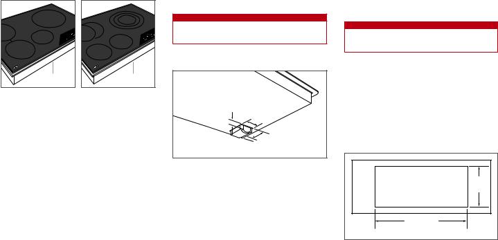
Important product information including the model and serial number are listed on the product rating plate. The rating plate is located on the bottom of the cooktop. Refer to the illustration below.
If service is necessary, contact Wolf factory certified service with the model and serial number.
RATING PLATE |
RATING PLATE |
Induction cooktop. |
Electric cooktop. |
SPECIFICATIONS
Installation Requirements
A minimum height clearance of 159 mm is required from the top of the countertop to any combustible surface directly below the cooktop.
Clearance is required for the power inlet box located at the right rear of induction and electric cooktops. Refer to the illustration below for dimensions.
Refer to the illustrations on pages 3–4 for additional minimum clearances. Installation dimensions are the same for induction and electric cooktops of the same width.
 WARNING
Failure to locate the cooktop without proper clearances will result in a fire hazard.
32 mm
56 mm
 38 mm
38 mm
84
40  mm mm
mm mm
Power inlet box clearance.
FLUSH INSTALLATION
Contemporary induction and electric cooktops can be mounted flush with the top of the countertop, or as a frameless installation sitting on top of the countertop surface. If the cooktop is to be mounted flush with the countertop, a recessed area surrounding the cooktop cut-out must be provided. Wolf downdraft systems cannot be used with contemporary induction and electric cooktops.
An installation kit and instructions required for a flush installation are provided with the contemporary cooktop.
 CAUTION
Flush installation is intended for granite, solid surface or stone countertop surfaces only.
MULTIPLE COOKTOPS
When multiple cooktops or modules are installed side by side, the countertop cut-out width is determined by adding the width of each unit, then subtracting 25 mm. Refer to the illustration below.
IMPORTANT NOTE: Contemporary induction and electric cooktops are not designed to be installed in combination with other cooktops.
64 mm |
495 mm |
CUT-OUT |
DEPTH |
64 mm |
CUT-OUT WIDTH
(COMBINED WIDTH OF COOKTOPS MINUS 25 mm)
Countertop cut-out.
2 | English
SPECIFICATIONS
Electrical
Installation must comply with all applicable electrical codes and be properly grounded (earthed).
Locate the electrical supply as shown in the illustrations on pages 3–4. A separate circuit, servicing only this appliance is required. A ground fault circuit interrupter (GFCI) is not recommended and may cause interruption of operation.
Performance may be compromised if the electrical supply is less than 220 volts.
When multiple cooktops are installed side by side, each unit must have its own separate recommended electrical circuit.
REQUIRED POWER SUPPLY
INDUCTION / ELECTRIC |
|
|
Single phase |
220-240V AC, 50/60 Hz |
|
3phase |
380-415V AC, 50 Hz |
|
MAXIMUM CONNECTED LOAD |
|
|
INDUCTION COOKTOPS |
SINGLE PHASE |
3PHASE |
381 mm |
3.7 kW |
3.7 kW |
610 mm |
6.85 kW |
3.7 kW |
762 mm |
7.4 kW |
3.7 kW |
914 mm |
11.1 kW |
3.7 kW |
ELECTRIC COOKTOPS |
SINGLE PHASE |
3PHASE |
381 mm |
2.9–3.4 kW |
2.9–3.4 kW |
762 mm |
6.2–7.5 kW |
3.3–3.9 kW |
914 mm |
8.9–10.5 kW |
3.4–4.0 kW |
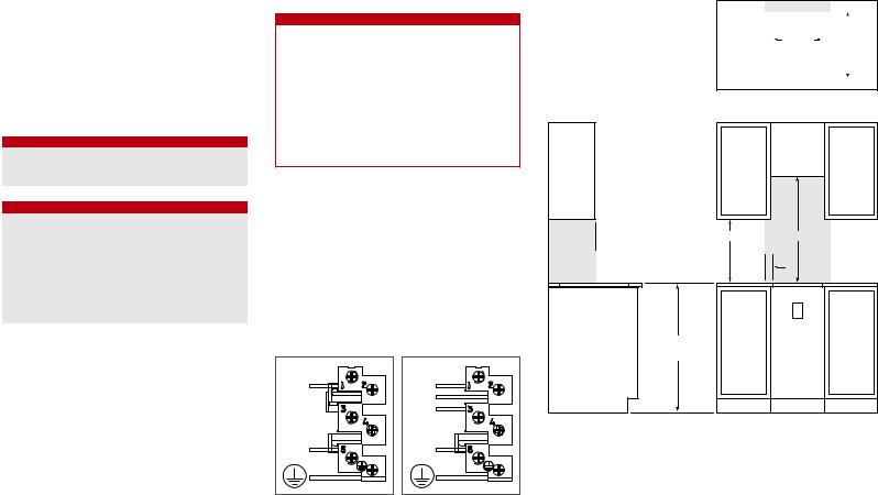
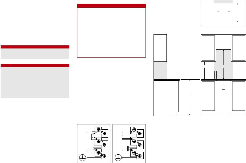
Refer to the wiring diagram showing the connections for each lead to the terminal box on the unit.
 WARNING
The complete appliance must be properly grounded at all times when electrical power is applied.
Do not ground appliance with the neutral (white) house supply wire. A separate ground wire must be utilized.
If aluminum house supply wiring is utilized, splice the appliance copper wire to the aluminum house wiring using special connectors design and agency certified for joining copper and aluminum. Follow the connector manufacturer’s recommended procedure carefully. Improper connection can result in a fire hazard.
IMPORTANT NOTE: Connection of this appliance should be through a fused connection unit or a suitable isolator, which complies with national and local safety regulations. The on/off switch should be easily accessible after the appliance has been installed. If the switch is not accessible after installation (depending on country) an additional means of disconnection must be provided for all poles of the power supply. When switched off there must be an all pole contact gap of 3 mm in the isolator switch. This 3 mm contact disconnect gap must apply to any isolator switch, fuses and/or relays according to EN60335.
˜ L1 |
N |
3N ˜ |
L1 |
L2 |
L3 |
N |
Single phase wiring diagram. |
3phase wiring diagram. |
381 mm Cooktop
STANDARD INSTALLATION
64 mm
343 mm |
|
|
|
|
|
|
|
|
495 mm |
||
|
|
|
|
|
|
|
|
64 mm
COUNTERTOP CUT-OUT
 330 mm
457 mm |
762 mm |
51  mm
mm
E
914 mm min FLOOR TO COUNTERTOP
SIDE VIEW |
FRONT VIEW |
NOTE: Shaded area above countertop indicates minimum clearance to combustible surfaces, combustible materials cannot be located within this area.
wolfappliance.com | 3

SPECIFICATIONS
610 mm, 762 mm and 914 mm Cooktops
STANDARD INSTALLATION
|
64 mm |
W |
495 mm |
WIDTH |
|
|
64 mm |
COUNTERTOP CUT-OUT |
|
 330 mm
914 mm min FLOOR TO COUNTERTOP
457 mm |
762 mm |
51  mm
mm
114 mm
89 mm |
|
E |

 254 mm
SIDE VIEW |
FRONT VIEW |
NOTE: Shaded area above countertop indicates minimum clearance to combustible surfaces, combustible materials cannot be located within this area.
Electrical supply location only applies to installations with built-in oven.
CUT-OUT WIDTH
INDUCTION / ELECTRIC COOKTOP |
W |
610 mm Induction |
562 mm |
762 mm Induction / Electric |
724 mm |
914 mm Induction / Electric |
876 mm |
610 mm, 762 mm and 914 mm Cooktops
FLUSH INSTALLATION
COUNTERTOP |
|
|
64 mm |
|
|
|
|
PROFILE |
|
|
|
22 |
537 mm |
W |
495 mm |
mm MAX |
CUT-OUT WIDTH |
||
|
RECESS |
A |
|
|
|
|
|
|
|
RECESS |
|
8 mm |
|
|
|
|
40 mm min |
|
64 mm |
|
|
COUNTERTOP CUT-OUT |
|
 330 mm
914 mm min FLOOR TO COUNTERTOP
457 mm |
762 mm |
51 mm
mm
114 mm
89 mm |
|
E |

 254 mm
SIDE VIEW |
FRONT VIEW |
NOTE: Shaded area above countertop indicates minimum clearance to combustible surfaces, combustible materials cannot be located within this area.
Electrical supply location only applies to installations with built-in oven. Outside corner radius 11 mm.
CUT-OUT WIDTH
INDUCTION / ELECTRIC COOKTOP |
W |
A |
610 mm Induction |
562 mm |
603 mm |
762 mm Induction / Electric |
724 mm |
765 mm |
914 mm Induction / Electric |
876 mm |
918 mm |
4 | English
INSTALLATION
Flush Installation
To ensure a proper installation, a template for the countertop cut-out should be created using the cooktop glass.
ROUTING OPTION
For this installation, a recessed area surrounding the countertop cut-out is required. Fabrication of the recessed area must take place before the countertop is installed.
This option is not recommended for countertops with a molded backsplash.
CLEAT OPTION
For this installation, the countertop cut-out will be the same size as the outer edge of the cooktop glass.
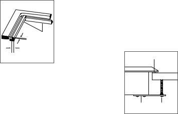
Attach L-shaped cleats to the perimeter of the countertop cut-out. The top edge of the cleat can not be wider than 22 mm and will be attached 8 mm below the surface of the countertop. Refer to the illustration below. Attach the cleats to the countertop. Consult a countertop supplier for proper methods of attachment.
8 mm |
L-SHAPED |
CLEATS |
22 mm |
Support cleats.
Cooktop Installation
Remove the cooktop and components from the shipping package and recycle packing materials.
Lower the cooktop into the countertop cut-out. Center the cooktop in the opening with the front edge aligned parallel to the front edge of the countertop. Using a pencil, outline the rear edge of the cooktop on the countertop. Remove the cooktop.
Apply the foam strip provided, to the perimeter of the countertop opening. Refer to the illustration below. Do not seal the cooktop to the countertop.
Insert the cooktop into the opening. Verify the cooktop is aligned with the front edge of the countertop.
Attach the brackets provided, to the bottom of the unit. Insert the 89 mm clamping screws into the brackets. Use a screwdriver to tighten the clamping screws against the bottom of the countertop. Do not overtighten screws. Refer to the illustration below.
FOAM STRIP |
|
|
COUNTERTOP |
BRACKET |
CLAMPING |
|
SCREW |
Cooktop installation.
Troubleshooting
IMPORTANT NOTE: If the cooktop does not operate properly, follow these troubleshooting steps:
•Verify electrical power is supplied to the cooktop.
•If the cooktop does not operate properly, contact Wolf factory certified service. Do not attempt to repair the cooktop. Wolf is not responsible for service required to correct a faulty installation.
Wolf, Wolf & Design, Wolf Gourmet, W & Design and the color red as applied to knobs are registered trademarks and service marks of Wolf Appliance, Inc. Sub-Zero, Sub-Zero & Design, Dual Refrigeration, The Living Kitchen, Great American Kitchens The Fine Art of Kitchen Design, and Ingredients are registered trademarks and service marks of Sub-Zero, Inc. (collectively, the “Company Marks.”) All other trademarks or registered trademarks are property of their respective owners in the United States and other countries.
wolfappliance.com | 5
PLACAS VITROCERÁMICAS Y DE INDUCCIÓN |
ESPECIFICACIONES |
Índice
6 Placas vitrocerámicas y de inducción
6 Especificaciones
9 Instalación
9 Localización y solución de problemas
Las características y especificaciones están sujetas a cambios sin previo aviso.
Nota importante
Para garantizar que este producto se instala y funciona de la forma más eficaz y segura posible, tenga en cuenta la información que se destaca en esta guía:
Cuando aparece NOTA IMPORTANTE, se resalta información que resulta especialmente importante.
PRECAUCIÓN indica una situación en la que se pueden sufrir heridas leves o provocar daños al producto si no se siguen las instrucciones.
AVISO indica el peligro de que se produzcan heridas graves o incluso la muerte si no se respetan las precauciones.
NOTA IMPORTANTE: conserve estas instrucciones para el inspector eléctrico local.
Información sobre el producto
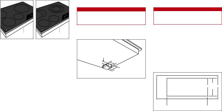
En la placa de datos del producto encontrará información importante, incluyendo el modelo y el número de serie. La placa de datos está ubicada en la parte inferior del aparato. Observe la siguiente ilustración.
Si necesita recurrir a un servicio técnico, póngase en contacto con un servicio de Wolf certificado con el modelo y el número de serie.
PLACA DE DATOS |
PLACA DE DATOS |
Placa de inducción. |
Placa vitrocerámica. |
Requisitos de instalación
Es necesario dejar un espacio mínimo de altura de 159 mm entre la parte superior de la encimera y cualquier superficie combustible que se encuentre justo debajo de la placa.
Se necesita dejar un espacio para el bloque de terminales en la parte trasera derecha de las placas vitrocerámicas y de inducción. Observe la siguiente ilustración para ver las medidas.
Consulte las ilustraciones de las páginas 3 y 4 para más información sobre las distancias mínimas. Las medidas de instalación son las mismas para las placas vitrocerámicas y de inducción del mismo ancho.
 AVISO
AVISO
Si no coloca la placa siguiendo las distancias de separación correctas, es posible que se produzca un incendio.
32 mm
56 mm
 38 mm
38 mm
84
40  mm mm
mm mm
Distancia del bloque de terminales.
INSTALACIÓN EMPOTRADA
Las placas vitrocerámicas y de inducción contemporáneas se pueden instalar empotradas con la parte superior
de la encimera o como una instalación sin marco sobre la superficie de la encimera. Si la placa se instala
empotrada en la encimera, se necesitará un área acoplada alrededor del corte de la placa. No se pueden utilizar las campanas extractoras de encimera de Wolf con las placas vitrocerámicas y de inducción contemporáneas.
La placa contemporánea incluye un kit de instalación y las instrucciones necesarias para una instalación empotrada.
 PRECAUCIÓN
La instalación empotrada está diseñada para colocarse únicamente en superficies sólidas, de granito o en encimeras de piedra.
VARIAS PLACAS
Cuando se instalen varias placas o módulos juntos, el ancho de corte de la encimera se determina sumando el ancho de cada unidad y, a continuación, restando 25 mm. Consulte la siguiente ilustración.
NOTA IMPORTANTE: las placas vitrocerámicas y de inducción contemporáneas no están diseñadas para instalarse junto con otras placas.
64 mm |
495 mm |
PROFUNDIDAD |
DEL CORTE |
64 mm |
 ANCHURA DEL CORTE
(ANCHO COMBINADO DE LAS PLACAS MENOS 25 mm)
Corte de la encimera.
6 | Español
ESPECIFICACIONES
Potencia
La instalación debe cumplir con todas las normativas eléctricas aplicables y debe estar correctamente conectada a tierra.
Localice la toma eléctrica tal como se indica en las ilustraciones en las páginas 3-4. Se necesita un circuito independiente para esta unidad. No se recomienda utilizar un interruptor de circuito de fallos de toma de tierra (GFCI), ya que puede interrumpir el funcionamiento de la unidad.
El rendimiento puede verse afectado si el suministro eléctrico es inferior a 220 voltios.
Cuando se instalen varias placas juntas, cada unidad debe tener su propio circuito eléctrico recomendado.
ALIMENTACIÓN NECESARIA
VITROCERÁMICA / DE INDUCCIÓN |
|
|
Cableado monofásico |
220-240 V CA, 50/60 Hz |
|
Trifásico |
380-415 V AC, 50 Hz |
|
CARGA MÁXIMA CONECTADA |
|
|
PLACAS DE INDUCCIÓN |
MONOFÁSICO |
TRIFÁSICO |
381 mm |
3,7 kW |
3,7 kW |
610 mm |
6,85 kW |
3,7 kW |
762 mm |
7,4 kW |
3,7 kW |
914 mm |
11,1 kW |
3,7 kW |
PLACAS VITROCERÁMICAS |
MONOFÁSICO |
TRIFÁSICO |
381 mm |
2,9–3,4 kW |
2,9–3,4 kW |
762 mm |
6,2–7,5 kW |
3,3–3,9 kW |
914 mm |
8,9–10,5 kW |
3,4–4,0 kW |
Consulte el cuadro de conexiones que muestra las conexiones de cada cable a la caja de cables en la unidad.
 AVISO
AVISO
El aparato debe estar conectado a tierra de manera correcta siempre que esté conectado a la red eléctrica.
No conecte a tierra el aparato con el cable neutro (blanco) de la instalación de la vivienda. Debe utilizar un cable de conexión a tierra independiente.
Si utiliza el cable de aluminio de la instalación de la vivienda, empalme el cable de cobre del aparato al cable de aluminio de la vivienda utilizando conectores especiales diseñados y autorizados por el organismo regulador para unir el cable y el aluminio. Realice el procedimiento recomendado por el fabricante del conector. Si la conexión no se realiza de manera correcta, existe riesgo de que se produzca un incendio.
NOTA IMPORTANTE: la conexión de este aparato debe realizarse a una unidad de conexión con fusibles o a un aislador adecuado, que cumpla con las normativas de seguridad nacionales y locales. El interruptor de encendido/ apagado debe situarse en un lugar accesible después de haber instalado el aparato. Si no es posible acceder al interruptor después de la instalación (según el país), se deberá suministrar un medio de desconexión adicional para todos los polos de la alimentación eléctrica. Al estar desconectado, deberá existir una separación de contacto entre todos los polos de 3 mm en el interruptor del aislador. Esta separación de 3 mm de desconexión de los contactos deberá aplicarse a cualquier interruptor, fusibles o relés del aislador según la norma EN60335.
Placa de 381 mm
INSTALACIÓN ESTÁNDAR
64 mm
343 mm |
|
|
|
|
|
|
|
|
495 mm |
||
|
|
|
|
|
|
|
|
64 mm
CORTE DE LA ENCIMERA
 330 mm
457 mm |
762 mm |
51  mm
mm
E
914 mm mín DEL SUELO A LA ENCIMERA
˜ L1 |
N |
Diagrama de cableado monofásico.
3N ˜ |
L1 |
L2 |
L3 |
N |
Diagrama de cableado trifásico.
VISTA LATERAL |
VISTA FRONTAL |
NOTA: el área sombreada sobre la encimera indica la distancia mínima a superficies combustibles, por lo que no puede haber materiales combustibles en esta área.
wolfappliance.com | 7
 Loading...