


OF49P32SM
SERVICE MANUAL
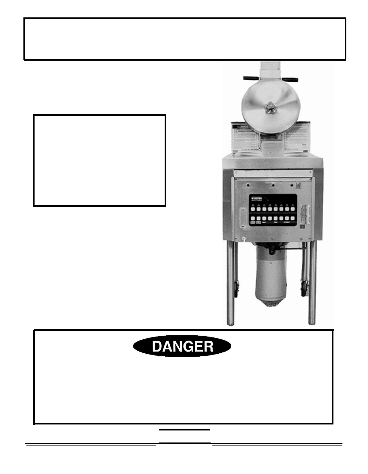
WINSTON COLLECTRAMATIC
FRYER
8 CHANNEL MODELS
4 HEAD & 6 HEAD
MANUAL REORDER: LIT.
The procedures contained in this manual involve accessing
6710/REV.0/9-91
bare
electrical terminals and
exposure to voltages capable of producing serious
diagnoisis
components
electrical service while performing the procedures listed in
and/or
must
repair involving removal of
be trained or experienced in such service procedures. Disconnect
injury
panels
WINSTON
PRODUCTS COMPANY
2345
CARTON DRIVE . LOUISVILLE, KENTUCKY . 40299 . (800)
or death. Any person attempting
and/or exposure to
this
manual.
234-5286
live
electrical
. FAX: (502)495-5458

INTRODUCTION
This Service Manual is to be used for the following WINSTON COLLECIRAMATIC FRYERS:
PRESSURE FRYERS OPEN FRYERS
MODEL NO. MODEL NO
PFWPC4201 CASJ(or M) OFWPC4201
PFWPC6201 CASJ(or M) OFWPC6201
PF46P32 SJ(or
PF56P32 SJ(or
PF46P37 SJ(or
PF56P37 SJ(or
PFWPC4201 SJ(or M) OFWPC4201 SJ(or M)
PFWPC6201 SJ(or M) OFWPC6201 SJ(or M)
PFWPC4201 NZSN OFWPC4201 NZSN
PFWPC6201 NZSN OFWPC6201
PFWPC4201 MASN OFWPC4201
PFWPC6201 MASN OFWPC6201 MASN
PF46P44 SN OF49P44 SN
PF56P44 SN OF59P44 SN
PFWPC4201
PFWPC6201
PF46P45SN OF49P45 SN
PF56P45SN OF59P45 SN
M) OF49P32SJ(or M)
M) OF59P32SJ(or M)
M) OF49P37SJ(or M)
M) OF59P37SJ(or M)
AUSN OFWPC4201 AUSN
AUSN OFWPC6201 AUSN
OFWPC4201AUSN
OFWPC6201AUSN
OF59
OF59P45SN
.
CASJ(or M)
CASJ(or M)
NZSN
MASN
NOTE: The letter 'J' on the end of the Model Number denotes 208 volts and
'M' denotes 240 volts. To determine the intended market for the above listed
model numbers, refer to wiring diagrams listed between pages 18 through 25.
Knowledge of the proper installation, operation, and maintenence procedures is an
important step to insure safe operation of any equipment. The instructions in this manual are
meant as guidelines for proper service of the WINSTON COLLECTRAMATIC FRYER.
In accordance with generally accepted products safety labeling guidelines for potential hazards,
the following two signal words are used throughout this service manual where applicable:
DANGER: Used to indicate the presence of a hazard which could cause substantial property
damage, severe personal injury or death if warning is ignored.
CAUTION: Used to indicate the presence of a hazard which could cause minor property
damage or personal injury if warning is ignored.
DANGER: THE PROCEDURES CONTAINED IN THIS MANUAL INVOLVE ACCES-
SING BARE ELECTRICAL TERMINALS AND EXPOSURE TO VOLTAGES
CAPABLE OF PRODUCING SERIOUS INJURY OR DEATH. ANY PERSONS
ATTEMPTING DIAGNOSIS AND/OR REPAIR INVOLVING REMOVAL OF
PANELS AND/OR EXPOSURE TO LIVE ELECTRICAL COMPONENTS MUST
BE TRAINED OR EXPERIENCED IN SUCH SERVICE PROCEDURES.
DISCONNECT ELECTRICAL SERVICE WHILE PERFORMING THE PROCEDURES LISTED IN THIS MANUAL.
WINSTON
1
LIT.6710/REV.0/9-91

TABLE OF CONTENTS
PAGE No.
INTRODUCTION
TABLE OF CONTENTS
PARTS IDENTIFICATION
TROUBLESHOOTING
AMPERAGE / OHM VALUE CHARTS
...................................
..............................
...........................
..............................
...................
WlRlNG DIAGRAMS
PRESSURE FRYERS
OPEN FRYERS
..........................
...............................
REPLACEMENT PROCEDURES
ELECTROMECHANICAL RELAYS
MERCURY RELAY
TRANSFORMER
FUSE HOLDER
POWER BOARD
HI LIMIT THERMOSTAT
PROBE
.....................................
ON/OFF SWlTCH
LID VALVE O-RING
LID LOCK ASSEMBLY
LID VALVE ASSEMBLY
HANDLEBAR
HEATER HOLDER
FUSE
.......................................
DANGER LABEL
WHEEL
.....................................
VENT ASSEMBLY
TEFLON SLIDE
COTTER PIN
VENT TUBE O-RING
WEIGHT LIFTER
VENT TUBE
WEIGHT
................................
...................................
HINGE BLOCK (REAR)
VENT SPRING
VENT SOLENOID
DRAIN VALVE
INDICATOR LAMP
VENT BLOCK
LATCH BLOCK (FRONT)
MAIN CIRCUIT BOARD
OBTAINING SERVICE.
...........................
.............................
...............................
..............................
.......................
.............................
...........................
........................
.......................
................................
............................
.............................
...........................
.............................
................................
..........................
.............................
........................
...............................
............................
..............................
...........................
...............................
......................
.......................
........................
...............
1
2-3
4- 13
4- 16
17
18-21
22-25
26-25
26-27
27
27-28
28-29
31-32
32-33
34
34,35
35
36
36
37
37-38
38
38
38-40
40-42
44-45
44-45
46-47
47-49
49
49-51
51-53
53-55
55-56
56
57-58
57-59
59
60
WINSTON
2
LIT.6710/REV.0/9-91

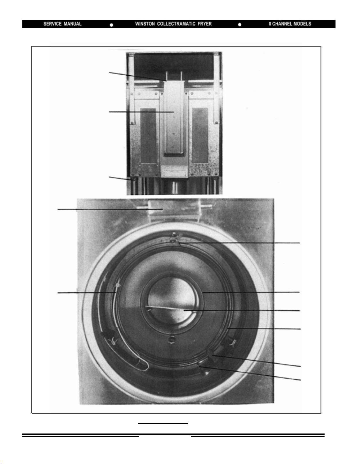
1
2
3,4,
5,6
7
8
9
10
11
12
Escutcheon
(Ref Only)
(Inside Lid Groove)
15
16
17
18
19
ID
Tag
(Ref Only)
22
23
13
14
WINSTON
4
20
21
24
25
LIT.6710/REV.0/9-91
29
26
27
28
30
High limit
Thermostat Bulb
(Refrence Only)
31
32
(under)
33
34
35
36
WINSTON
5
LIT.6710/REV.0/9-91
37
38
42
(If Applicable)
39
40
41
43
(Behind)
44
NOTE: 6-Head Model Picture
WINSTON
6
LIT.6710/REV.0/9-91
45
46
51
47
48
49
50
52
53
(Inside)
54
(Behind)
55
WINSTON
7
LIT.6710/REV.0/9-91

56
57
58
59
-
61
62
(Behind)
NOTE: 6-Head Model Pictured
60
WINSTON
8
LIT.6710/REV.0/9-91
PARTS IDENTIFICATION
Photo
Item
No.
1 Lid Lock PS1449
2 Handle Bar PS1168
3 Lid Valve Assembly PS1127
4
5
6
7
8
Lid Valve Spring PS1028/3
Lid Valve Retainer PS1057
Lid Valve O-Ring PS1010/3
Danger Panel PS1210
Latch Block (Front) PS1399
Part Description Order
Number Qty. Description
1 Lid Lock
1 Handle
1 Valve Body
1 Spring
1 Retainer
1 O-Ring
3 Spring
1 Retainer
3 O-Ring
1 Panel
1 Block
3 Washer
3 Lockwasher
3 Nut- Flex Lock
Kit Content
9
10
11 ‘Heat On’ Indicator Lamp PS1012/3
12 Membrane Panel PS1748
13 Drain Valve PS1066
14
15
16 Lid PS1046
Eyebrow PS1134
'High Limit’ Indicator Lamp PS1012/3
Collector
13”
11” PS1925
Lid Gasket PS1891/3
PS1206
3 Lamp
1 Eyebrow
3 Lamp
1 Panel
1 Valve
1 Valve Plate
2 Screw
2 Nut
1 Collector
1
Heat Plate
3 Gasket
1 Lid- Pressure Lock
WINSTON
9
LIT.6710/REV.0/9-91
PARTS IDENTIFICATION
Photo
Item
No.
17 Screw PS1118/6
18 Switch Guard PS1086
19 Power Indicator Lamp PS1012/3
20
Drain Valve Handle PS1695
21
Leg PS1142/2 2 Leg
22
Screw PS1241/6
23
Back Panel
4 - Head PS1697
6 - Head PS1698
24 Muffler PS1152
Part Description Order
Number Qty. Description
6 Screw
1 Guard
3 Lamp
2 Screw
1 Handle
2 Nut
1 Bracket
6 Screw
2 Panels
1 Muffler
Kit Content
25 Wheel Assembly PS1226/2
26 Vent Back Cap PS1729
27
Vent Back Assembly PS1156
28
Leg Clamp Assembly PS1621
29
Hinge Block (Rear) PS1400
2 Wheel - 4"
2 Bolt
2 Nut
1 Cap
1 Nut
1 Vent Back
2 Spring
2 Rod
1 Cap
1 Nut
1 Clamp
2 Screw
2 Nut
1 Hinge Block
3 Washer
3 Lockwasher
3 Nut
WINSTON
10
LIT.6710/REV.0/9-91

PARTS IDENTIFICATION
Photo
Item
No.
30
31
32
33
34
35
‘High Limit’
Heater Holder
Collector Gasket
Heat Plate
14.75”
12.75”
Heater Assembly
208 Volts
240 Volts PS1148
Probe Guard PS1744
Part Description Order
Number Qty. Description
T’Stat
Clamp
PS1312
PS1430/3
PS1892/3
PS1034
PS1918
PS1147
1 Clamp
1 Screw
3 Heater Holder
3
1 Heat Plate
1 Heater Coil
6 Ferrule
2 Nut
2 Compression Nut
2 Washer
1 Probe Guard
1 Screw
Kit Content
Gasket
36
Probe Assembly PS1747 1 Probe
1 Washer
37 Grommet PS1263/6 6 Grommet
38 Weight 1 Weight
4 - Head (14 PSI) PS1071
4 - Head(11.9PSI) PS1072
6 - Head(11.9PSI) PS1073
NOTE: For identifying correct
weight when ordering, read
PSI engraved on weight lifter.
39
Vent Block Assembly
4 - Head PS1026
-
Head PS1684
6
PS1684
1 Block
1 O-Ring
4
Screw
1 Nut Plate
1 Plug
WINSTON
11
LIT.6710/REV.0/9-91
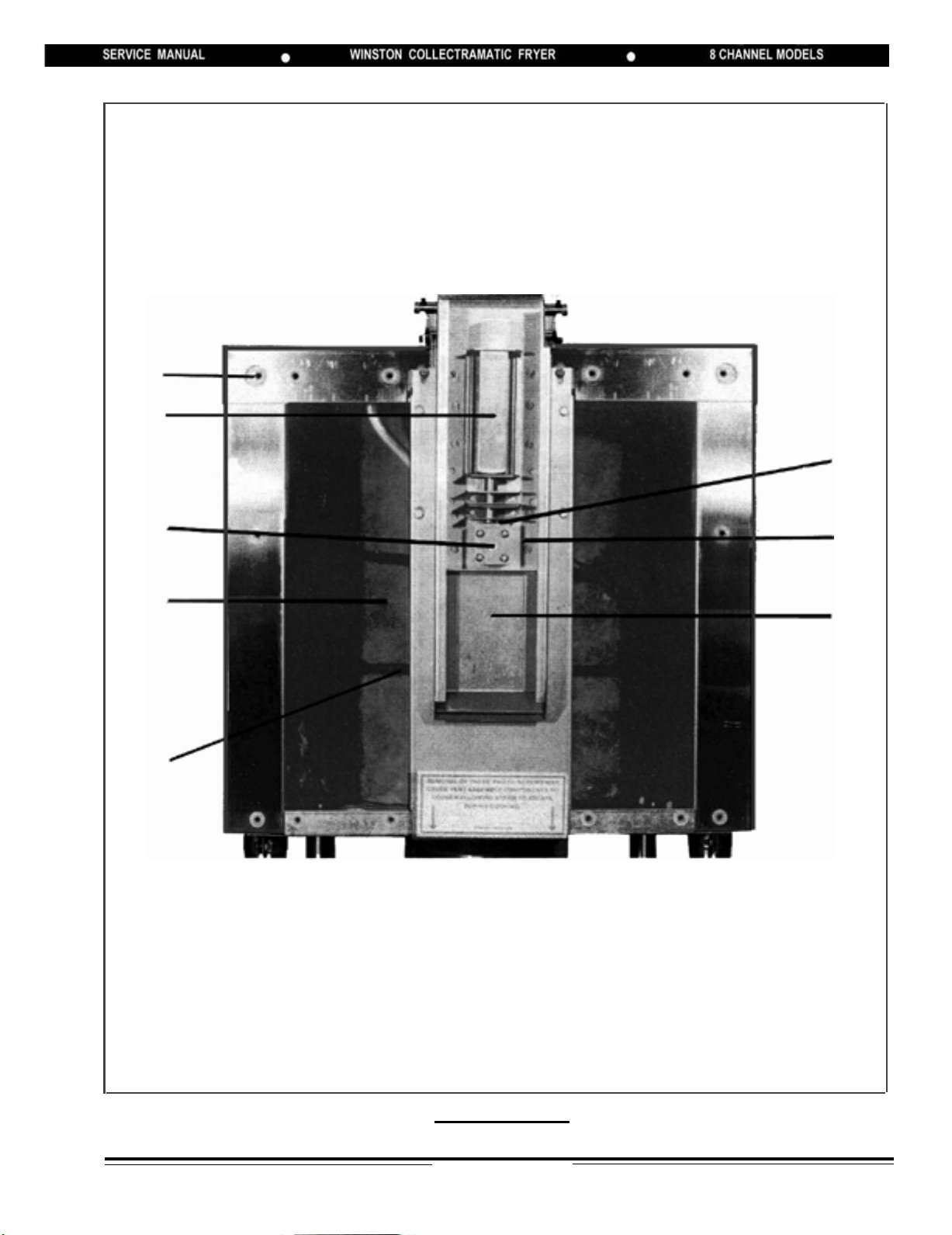
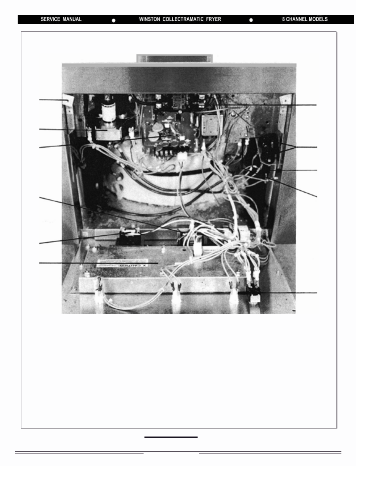
PARTS IDENTIFICATION
Photo
Item
No.
40 Insulation 1 Insulation - Front
4 - Head PS1031
6 - Head PS1792
41 Insulation Strap PS1219/2 2 Strap
42 Vent Ball 3 Vent Ball
4 - Head (If applicable) PS1003/3
6 - Head (If applicable) PS1685/3
43 Vent Tube O-Ring PS1005/3 3 O-Ring
44 Vent Assembly 1 Weight Lifter
4 - Head PS1458
6 - Head PS1686
Part Description Order
Number Qty. Description
1 Insulation - Back
2 Strap
2 Buckle
2 Buckle
1 Teflon Slide
2 Solenoid Wires
1 Vent Weld Asm
1 Solenoid
1 Spring
1 Bracket
8 Nut
8 Screw
1 Cotter Pin
Kit Content
45 Grommet PS127l/6 6 Grommet
46 Mercury Relay PS1448 1 Relay
47 Circuit Board - Power PS1800 1 Circuit Board
48 Transformer PS1687 1 Transformer
49 Buzzer PS1586 1 Buzzer
50 Computer 1 Computer
General Market PS1745
KFC (All markets excluding Canada) PS1927
KFC (Canada) PS1848
WINSTON
12
LIT.6710/REV.0/9-91

PARTS IDENTIFICATION
Photo
Item
No.
51
52
53
54
55
56
57
58
Electromechanical Relay PS1007 1 Relay
Fuse Holder PS1096/2 2 Fuse Holder
Fuse Kit PS1095/6 6 Fuse
High Limit Thermostat PS1184 1 Thermostat
" " " Canadian
On/Off
Vent Tube 1 Tube
4 - Head PS1322
6 - Head PS1678
Vent Block Nut Plate PS1704/6 6 Nut Plate
Vent Solenoid Spring PS1320/3 3 Spring
Part Description Order
Number Qty. Description
PS1731 1 Thermostat
Switch PS1529 1 Switch
Kit Content
59
60
61
62 Teflon Slide PS1075/3 3 Teflon Slide
Vent Solenoid PS1088 1 Solenoid
1 O-Ring
2 Terminal Ring
1 Cotter Pin
Vent Solenoid Cotter Pin PS1121/3 3 Cotter Pin
Weight Lifter
4 - Head
11.9 PSI PS1040
14.0 PSI PS1039
6 - Head - 11.9 PSI PS1041
PS1075/3
1 Weight Lifter
1 Teflon Slide
WINSTON
13
LIT.6710/REV.0/9-91

TROUBLESHOOTING
SYMPTOMS FAULTS
Electric shock while in contact with fryer. DANGER: Turn
OFF circuit breaker or disconnect fryer from power source
Low pressure . . . . . . . . . . . . . . . . . . . . . . . .. . . . . . . . . .15,16,17,18,22
No Pressure . . . . . . . . . . . . . . . . . . . . . . . . . . . . . . . . .19,21,20,22,23,40,4
Pressure loss excessive through Vent in rear of fryer. . . . .19,22,20,21,23
Pressure loss excessive through Lid Valve. . . . . . . . . . . . . 16,17,43
Not venting at end of cooking cycle . . . . . . . . . . . . . . . . . . . . . . . 20,25,43,44,45,23
No heat . . . . . . . . . . . . . . . . . . . . . . . . . . . . . . . . . . . . . . . . . . . 2,7,39,14,46,4,40
Heats slowly. . . . . . . . . . . . . . . . . . . . . . . . . . .. . . . . . . . . . . . 2,5,11,14,6
Heat On Lamp off when heating. . . . . . . . . . . . . . . . . . . . . . . . . . 7,9
Heat On Lamp constantly ON during cook cycle. . . . . . 3,46,4
High Limit Lamp on continuously. . . . . . . . . . . . . . . . . . . 10,46,4
Power Lamp out or dim..
Electromechanical relay buzzing loudly. . . . . . . . . . . . . 7,24,14
.................................
. . . . . . . . . . . . . . . 1
2,9
Solenoid buzzing loudly. . . . . . . . . . . . . . .. . . . . . . . . . . 47,20,24,37
Shortening leaking from front of fryer. . . . . . . . . . . . . . . . . . 27,28
Shortening leaking around Collector Gasket. . . . . . . . . . . . 26,48
Shortening smoking . . . . . . . . . . . . . . . . . . . . . . . . . . . . . .29,30
Shortening too hot. . . . . . . . . . . . . . . . . . . . . . . . . . . . .3,42,4
Shortening has burnt or bad taste. . . . . . . . . . . . . . . . . . 31,30,13,33
Shortening foaming excessively. . . . . . . . . . . . . . . . . . 30
Shortening breaking down too quickly. . . . . . . . . . . . . 36,31,12,13,8
Shortening boils over. . . . . . . . . . . . . . . . . . . . . . . . . . . . . . . . . 32,33,34,35,38
“Probe”displayed in window. . . . . . . . . . . . . . . . . . . . . . 49,42,39,4
No Display in window. . . . . . . . . . . . . . . . . . . . . . . . . . 7,41,4
Fryer stops heating between170-230 on display . . . . . . . . . . . 50,51
Display shows ‘H O ' 50,51
. . . . . . . . . . . . . . . . . . . . . . . . . . . . . . . . . . . . . . . .
2
WINSTON
14
LIT.6710/REV.0/9-91
TROUBLESHOOTING
FAULTS
1 Improper ground, wiring short DANGER: Turn OFF
circuit breaker. . . . . . . . . . . . . . . . . . . . . . . . . . . . . . . . . . . .
2. Open power line
Circuit breaker tripped. . . . . . . . . . . . . . . . . . . . . . . . . . . .
Fuse blown . . . . . . . . . . . . . . . . . . . . . . . . . . . . . . . . . . . .
Cordset not plugged in . . . . . . . . . . . . . . . . . . . . . . . . . . .
Faulty power switch. . . . . . . . . . . . . . . . . . . . . . . . . . . . . .
3. Programming error in computer. . . . . . . . . . . . . . . . . . . . . . .
4. Computer defective. . . . . . . . . . . . . . . . . . . . . . . . . . . . . . . .
5. One of three circuits open in fryer. . . . . . . . . . . . . . . . . . . . .
6. Heater wires connected wrong (3 ph. vs single ph). . . . . . . .
7. Loose wire connections. . . . . . . . . . . . . . . . . . . . . . . . . . . . .
8. 208 volt fryer installed on 240 volt supply. . . . . . . . . . . . . . .
9. Indicator Lamp burned out. . . . . . . . . . . . . . . . . . . . . . . . . . .
10. High Limit Thermostat defective. . . . . . . . . . . . . . . . . . . . . .
11. Heater(s) burned out. . . . . . . . . . . . . . . . . . . . . . . . . . . . . . .
12. Heaters misaligned. . . . . . . . . . . . . . . . . . . . . . . . . . . . . . . .
13. Heater(s) out of holders and touching. . . . . . . . . . . . . . . . . .
14. Electromechanical Relay Defective. . . . . . . . . . . . . . . . . . . .
15. Lid Gasket defective. . . . . . . . . . . . . . . . . . . . . . . . . . . . . . .
16. Lid Valve O-Ring not seating, defective. . . . . . . . . . . . . . . . .
17. Lid Valve Retainer loose. . . . . . . . . . . . . . . . . . . . . . . . . . . .
18. Weight dirty. . . . . . . . . . . . . . . . . . . . . . . . . . . . . . . . . . . . . .
19. Lost Vent Ball under weight in vent assembly
(if applicable - newer systems do not utilize ball). . . . . . . . .
20. Power Board defective. . . . . . . . . . . . . . . . . . . . . . . . . . . . . .
21. Solenoid defective. . . . . . . . . . . . . . . . . . . . . . . . . . . . . . . . .
22. Vent Tube O-Ring defective.. . . . . . . . . . . . . . . . . . . . . . . . .
23. Weight Lifter dirty or defective. . . . . . . . . . . . . . . . . . . . . . . .
24. Relay mounting is loose. . . . . . . . . . . . . . . . . . . . . . . . . . . . .
25. Vent Spring defective or missing. . . . . . . . . . . . . . . . . . . . . .
26. Collector Gasket dirty or defective. . . . . . . . . . . . . . . . . . . . .
27. Thermostat, Heater or Probe nuts on cooking vessel
wall loose. . . . . . . . . . . . . . . . . . . .. . . . . . . . . . . . . . . . . . . .
28. Thermostat, Heater or Probe ferrules damaged. . . . . . . . . . .
29. Shortening level below top heater . . . . . . . . . . . . . . . . . . . . .
30. Shortening badly broken down. . . . . . . . . . . . . . . . . . . . . . . .
31. Crackling build-up on heater coils. . . . . . . . . . . . . . . . . . . . .
32. Cracklings left in Collector from night before or overfilled. . .
33. Contents of Collector stirred after warm-up. . . . . . . . . . . . . .
34. Heat Plate left out of Collector. . . . . . . . . . . . . . . . . . . . . . . .
35. Solid shortening in Collector - improper warm-up. . . . . . . . .
36. Fryer not cleaned properly. . . . . . . . . . . . . . . . . . . . . . . . . . .
REMEDIES
CLEAN
ADJUST
REPAIR
REPLACE
WINSTON
15
LIT.6710/REV.0/9-91
TROUBLESHOOTING
FAULTS
37. Cotter pin too long or tight (must rotate freely). . . . . . . . . . .
38. Excessive moisture in shortening . . . . . . . . . . . . . . . . . . . .
39. Pin loose in molex connector on computer . . . . . . . . . . . . . .
40. Power board plug loose or off . . . . . . . . . . . . . . . . . . . . . . .
41. Transformer defective . . . . . . . . . . . . . . . . . . . . . . . . . . . . .
42. Probe defective. . . . . . . . . . . . . . . . . . . . . . . . . . . . . . . . . .
43. Shortening/crackling build up in vent tube. . . . . . . . . . . . . . .
44. Vent Ball stuck on Vent Block (if applicable). . . . . . . . . . . . .
45. Vent solenoid cotter pin missing. . . . . . . . . . . . . . . . . . . . . .
46. Mercury relay defective. . . . . . . . . . . . . .. . . . . . . . . . . . . .
47. Vent solenoid dirty. . . . . . . . . . . . . .. . . . . . . . . . . . . .. . . .
48. Collector Out of round - defective. . . . . . . . . . . . . .. . . . . . . .
49. Probe wire(s) disconnected from plug. . . . . . . . . . . . . . . . . .
50. Fryer filled with water (See Note 1). . . . . . . . . . . . . .. . . . . . .
51. Solid shortening being melted in fryer (See Note 2). . . . . . . .
REMEDIES
CLEAN
ADJUST
*
*
*
*
*
*
REPAIR
REPLACE
*
*
*
*
*
*
*
*
NOTE 1: This fryer is equiped with an AquaLert software system. Software is designed to
TM
stop the heat-up process prior to boiling point when water is detected in fryer. If
fryer is filled with water, empty, clean, dry thoroughly and fill with cooking oil.
NOTE 2: When solid shortening is being heated in fryer, the water detection software system
may respond as though water is being heated due to the slower heat curve experienced. When heating solid shortening, remove any pieces which may be lodged next
to temperature sensing probe.
WINSTON
16
LIT.6710/REV.0/9-91
AMPERAGE/OHM VALUE CHARTS
NOTE:
Resistance measurements are taken across coil of relays and terminal ends on
heaters. Wires must be removed from component prior to resistance check.
OHM CHART
DESCRIPTION OHMIC VALUE PART NO
Mercury Relay
Watlow
Duracool
Electromechanical Relay
Heater - 208V, 3500W
Heater - 240V, 3500W
690.0 OHMS +/- 10% PS1448
500.0 OHMS +/- 10% PS1448
225.0 OHMS +/- 10% PS1007
12.3 OHMS +/- 10% PS1147
16.4 OHMS +/- 10% PS1148
AMPERAGE CHART
ENGLAND/ ENGLAND/
USA & CANADA MALAYSIA/SINGAPORE MALAYSIA/SINGAPORE
PHASE VOLTAGE CURRENT CURRENT
LINE
(AMPS) (AMPS)
HEATER
208 - -
11
33
240 43.7 14.6
208 29.2 16.8
240 25.2 14.6
AUSTRALIA NEW ZEALAND SOUTH AFRICA
PHASE VOLTAGE CURRENT CURRENT
33
416 14.6 14.6
LINE
(AMPS) (AMPS) (AMPS) (AMPS)
HEATER
PHASE VOLTAGE CURRENT CURRENT
LINE
(AMPS) (AMPS)
HEATER
PHASE VOLTAGE CURRENT CURRENT
220 40.1 13.4 - - -
11
33
240 43.7 14.6
- - -
11
33
- - - 416 14.6 14.6
PHASE VOLTAGE CURRENT CURRENT
1111
33
- - -- - -
400 13.9 13.9
LINE
HEATER
PHASE VOLTAGE CURRENT CURRENT
11
33
LINE
(AMPS) (AMPS)
HEATER
- - -
380 13.4 13.4
LINE
(AMPS) (AMPS)
HEATER
- - -
380 13.4 13.4
CAUTION: 208 Volt Fryers are not to be used in single phase applications. Current produced
exceeds acceptable standards.
WINSTON
17
LIT.6710/REV.0/9-91
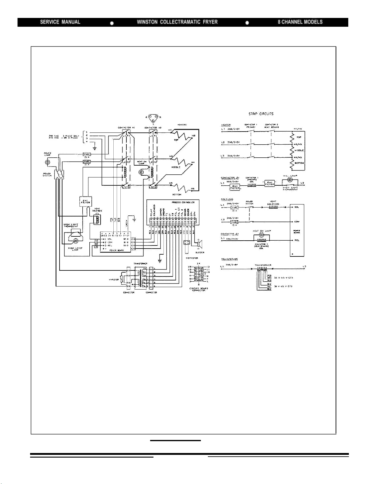
WIRING DIAGRAM
FOR MODELS NUMBERS:
PF46P32SJ (or M)
PF56P32SJ (or M)
PF46P37SJ (or M)
PF56P37SJ (or M)
Model numbers listed are as reflected on Identification Tag.
WINSTON
18
LIT.6710/REV.0/9-91
 Loading...