

Page 1
INSTALLATION INSTRUCTIONS
DSE 890 WebNet® GATEWAY
This instruction sheet is provided in assisting in the installation of the DSE890
module. For a complete DSE installation and operation manual please go to
DSE website @ www.deepseaplc.com. Document # 057-165.
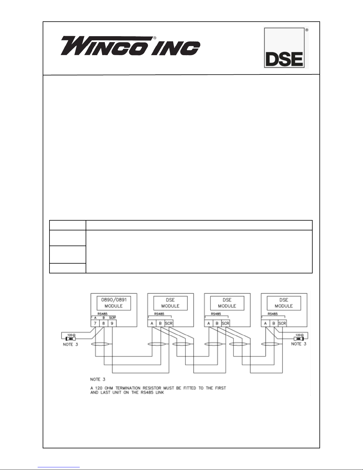
RS485 CONNECTOR
This socket provides support for connection to a maximum of 32 (thirty two) DSE
controllers in a daisy chain RS485 network.
Ensure termination resistors (120Ω) are fitted as shown to the ends of the link as per
RS485 standard.
PIN No. NOTES
A (-) Two core screened twisted pair cable.
120 Ω impedance suitable for RS485 use.
B (+)
SCR
Recommended cable type - Belden 9841
Max distance 1200m (1.2km) when using Belden 9841 or direct equiv
alent.
-
113273-00 60710-131
Page 2
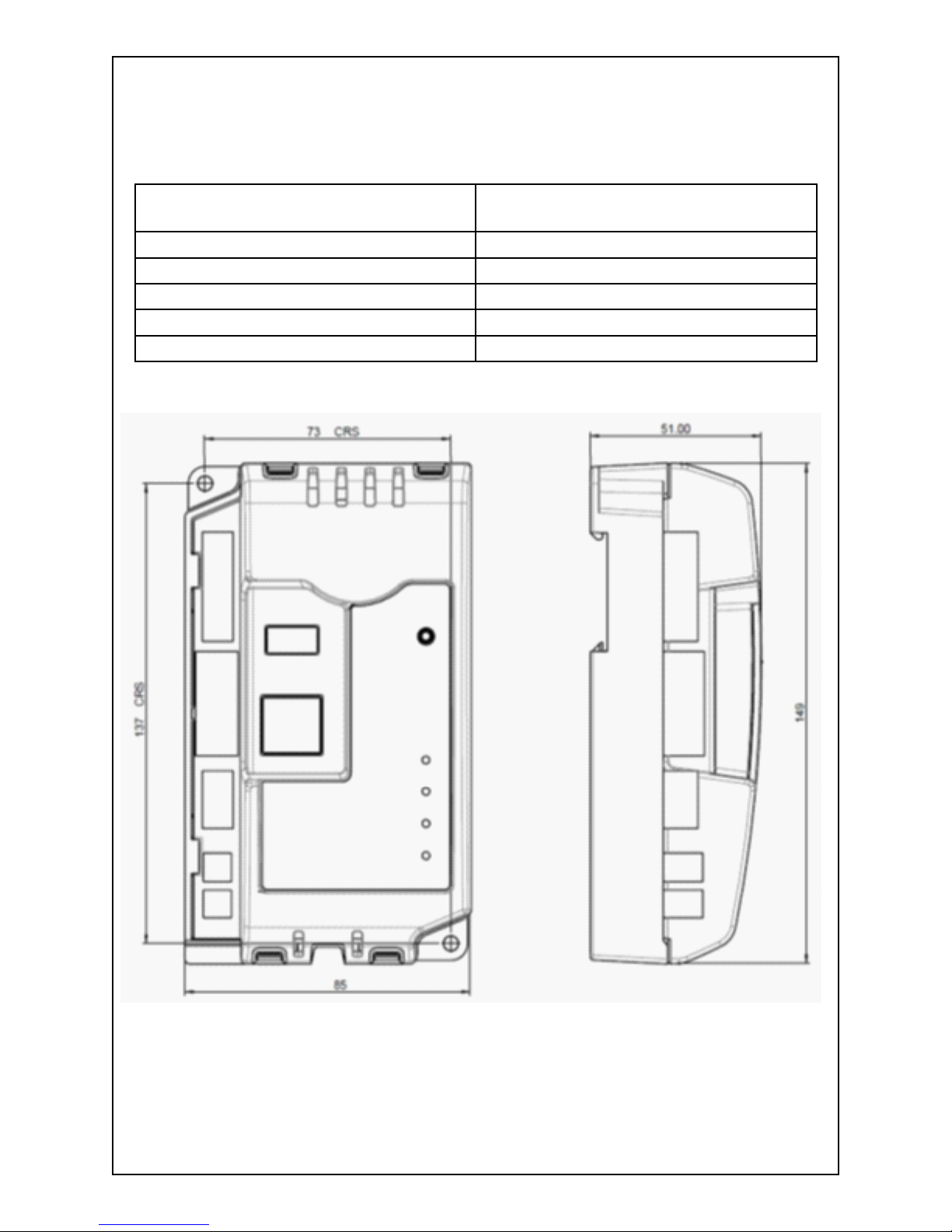
DIMENSIONS
Overall Size 85 mm x 149 mm x 51 mm
(3.35” x 5.85” x 2.01)
Weight 120g (4.23 oz)
Mounting Type DIN rail or chassis mounting
Din Rail Type EN 50022 35mm type only
Mounting Holes M4 clearance
Mounting hole centers 73 mm x 137 mm (2.89” x 5.39”)
213273-00 60710-131
Page 3

SIM CARD HOLDER (DSE 890 3G GATEWAY ONLY)
HOW TO INSERT THE 3G (OR 2G) GPRS SIM CARD
Pull back the upper
cover. It will click as it
unlocks.
Slide the SIM card, ensuring the “edge cutout”
is as shown.
Open the SIM card
holder, it hinges towards
you.
Close the cover, press
it down and slide it as
shown until it clicks into
place.
313273-00 60710-131
Page 4

TYPICAL WIRING DIAGRAM
SYSTEM OVERVIEW
DSE CONTROLLER(S)
Connection to DSE
Controller(s)
USB
•
RS232
•
RS485
•
Ethernet
•
DSE WEBNET SERVER
Connection to DSE
WebNet Server
Ethernet
•
GPRS (DSE890 only)
•
413273-00 60710-131
Page 5

CONTROLS AND INDICATIONS
RESET PUSHBUTTON
Reset Push Button Access Hole
LED1 LINK (Server) Status
LED2 USB Host Status
LED3 RS485 Status
LED4 RS232 Status
Press and hold the button to activate the reset sequence:
1. Press and HOLD the reset pushbutton.
2. All LED’s light YELLOW for a short time.
3. All LED’s extinguish for a short time.
4. LED’s illuminate one at a time - LED4, LED3, LED2, LED1.
5. All LED’s illuminate YELLOW.
6. Reset has completed and the reset push button can be released.
Once reset, the Gateway must be configured.
It’s factory set IP address is 192.168.1.100. Username:
Admin, Password:
Password1234.
LED INDICATIONS
LED FUNCTION COLOR ACTION
1 Server Status RED No Connection to host server
GREEN Connected to host server
2 USB Host Status RED Bad Data
GREEN Data Transfer OK
3 RS485 RED Bad Data
GREEN Data Transfer OK
4 RS232 RED Bad Data
GREEN Data Transfer OK
513273-00 60710-131
Page 6

ADDING THE CONTROLLER TO THE DSEGATEWAY
To ensure newly added controllers are recognised by the DSEGateway®, the
following steps must be followed. Failure to do so may result in communications
failure, indicated by a RED communications port LED.
• The DSEGateway®is factory set to accept connection via the USB port. If
this is not the port to be used, you must configure the DSEGateway®for the required port as detailed elsewhere in this document.
• Remove the DC supply from the DSEGateway®AND the connected
controller(s).
• Connect the new controller to the chosen communications port.
• Apply the DC supply to the controller being added (and any other control
-
lers in the system).
• Reapply the DSE supply to the DSEGateway®Gateway.
• For a short time (approx 10 seconds), the communication ports in use il
-
luminate RED.
• If correctly configured and connected, the ports will begin to flash GREEN
as data is received by the DSEGateway®.
• The LINK LED will illuminate GREEN when connection to the DSEWebNet
server is established.
This instruction sheet is provided in assisting in the installation of the
DSE890 module. For a complete DSE installation and operation manual
please go to DSE website @ www.deepseaplc.com. Document # 057-165.
Winco Inc.
Service Dept.
507-357-6831
613273-00 60710-131
 Loading...