


INSTRUCTION MANUAL
for
DGC-500
DIGITAL GENSET CONTROLLER
Publication: 9 3554 00 990
Revision: D |
03/04 |

INTRODUCTION
This manual provides information concerning the operation and installation of the Basler DGC-500 Digital Genset Controller. To accomplish this, the following information is provided.
•Specifications
•Functional Description
•Communication Software Description
•Installation Information
•Troubleshooting Information
WARNING!
To avoid personal injury or equipment damage, only qualified personnel should perform the procedures presented in this manual.
DGC-500 Introduction |
i |

First Printing: March 2002
Printed in USA
Copyright © 2004 Basler Electric, Highland, Illinois 62249 USA
March 2004
CONFIDENTIAL INFORMATION
Of Basler Electric. It is loaned for confidential use, subject to return on request, and with the mutual understanding that it will not be used in any manner detrimental to the interest of Basler Electric.
It is not the intention of this manual to cover all details and variations in equipment, nor does this manual provide data for every possible contingency regarding installation or operation. The availability and design of all features and options are subject to modification without notice. Should further information be required, contact Basler Electric.
BASLER ELECTRIC |
|
ROUTE 143, BOX 269 |
|
HIGHLAND, IL 62249 USA |
|
http://www.basler.com, info@basler.com |
|
PHONE 618-654-2341 |
FAX 618-654-2351 |
ii |
DGC-500 Introduction |

PRODUCT REVISION HISTORY
The following information provides a historical summary of the changes made to the embedded firmware, communication software (BESTCOMS), and hardware of this device. The corresponding revisions made to this instruction manual are also summarized. This revision history is separated into four categories: Firmware Version, BESTCOMS Version, Hardware Version, and Manual Version. All revisions are listed in reverse chronological order.
Firmware Version |
Summary |
|
|
|
|
2.04.XX - 10/03 |
C Added Engine Start/Stop Configuration setting to accommodate Volvo |
|
|
Penta EDC applications. Added CANBus Address setting and Genset kW |
|
|
Rating setting. |
|
2.03.XX - 03/03 |
C Added support for SAE J1939 interface and 400 Hz operation |
|
2.01.XX - 07/02 |
C Increased the maximum Sender Failure Alarm time delay setting from 10 |
|
|
seconds to 30 seconds. |
|
1.00.XX - 03/02 |
C Initial release |
|
|
|
BESTCOMS Version |
Summary |
|
|
|
|
1.03.XX - 10/03 |
C Added Engine Start/Stop Configuration setting to accommodate Volvo |
|
|
Penta EDC applications. Added CANBus Address setting and Genset kW |
|
|
Rating setting. |
|
1.02.XX - 03/03 |
C Added settings for support of SAE J1939 interface and 400 Hz operation. |
|
1.01.XX - 07/02 |
C Increased the maximum setting of the Global Sender Failure Alarm Time |
|
|
Delay from 10 seconds to 30 seconds. |
|
1.00.XX - 03/02 |
C Initial release |
|
|
|
Hardware Version |
|
|
|
(Standard Order P/N) |
|
Summary |
|
|
|
||
L - 10/03 |
C Implemented firmware version 2.04.XX and BESTCOMS version 1.03.XX |
||
K - 09/03 |
C Added reference to instruction manual on parts list |
||
J - 07/03 |
C Implemented firmware version 2.03.XX and BESTCOMS version 1.02.XX |
||
I |
C |
Not implemented |
|
H - 06/03 |
C Circuit board layout revised to improve manufacturing process |
||
G - 04/02 |
C |
Initial release |
|
|
|
|
|
DGC-500 Introduction |
iii |

Hardware Version |
|
|
(Special Order P/N) |
Summary |
|
|
|
|
D - 10/03 |
C Implemented firmware version 2.04.XX and BESTCOMS version 1.03.XX |
|
C - 09/03 |
C Added reference to instruction manual on parts list |
|
B - 07/03 |
C Implemented firmware version 2.03.XX and BESTCOMS version 1.02.XX |
|
A - 06/03 |
C Circuit board layout revised to improve manufacturing process |
|
|
|
Manual Version |
Summary |
|
|
|
|
D - 03/04 |
C Added suitability and warning statements concerning compliance of part |
|
|
numbers 9 3554 00 113 and 9 3554 00 114 with cURus Standard 1604. |
|
C - 09/03 |
C Added descriptions associated with new settings: CANBus Address, |
|
|
Engine Stop/Start Configuration, and Genset’s kW Rating. |
|
|
C Added information pertaining to DGC Isolator Kits. |
|
|
C Added Volvo Penta EDC application information and diagrams. |
|
|
C Updated Pre-Alarm and Alarm information in Section 3, Functional |
|
|
Description to include metric equivalents for settings. |
|
B - 03/03 |
C Revised style chart to show NFPA compliance as standard, J1939 support |
|
|
as optional. |
|
|
C Added coverage for part numbers 9 3554 00 111, 112, 113, and 114. |
|
|
C Added information about J1939 interface, ECU support, and state |
|
|
machine operation where appropriate. |
|
|
C Revised BESTCOMS section to accommodate new ECU settings. |
|
|
C Created new appendix of settings list with range for each setting. |
|
A - 07/02 |
C Added instructions to Section 3, Functional Description for viewing |
|
|
firmware version. |
|
|
C Revised the maximum setting of Sender Failure Alarm Time from 10 |
|
|
seconds to 30 seconds in Tables 3-1 and 3-2. |
|
|
C Replaced actual BESTCOMS version number in Figure 4-2 with generic |
|
|
version number. |
|
— - 02/02 |
C Initial release |
|
|
|
iv |
DGC-500 Introduction |

CONTENTS
SECTION 1 • GENERAL INFORMATION . . . . . . . . . . . . . . . . . . . . . . . . . . . . . . . . . . . . . . . . . . . . . . . . 1-1 SECTION 2 • HUMAN-MACHINE INTERFACE . . . . . . . . . . . . . . . . . . . . . . . . . . . . . . . . . . . . . . . . . . . 2-1 SECTION 3 • FUNCTIONAL DESCRIPTION . . . . . . . . . . . . . . . . . . . . . . . . . . . . . . . . . . . . . . . . . . . . . 3-1 SECTION 4 • BESTCOMS SOFTWARE . . . . . . . . . . . . . . . . . . . . . . . . . . . . . . . . . . . . . . . . . . . . . . . . . 4-1 SECTION 5 • INSTALLATION . . . . . . . . . . . . . . . . . . . . . . . . . . . . . . . . . . . . . . . . . . . . . . . . . . . . . . . . . 5-1 SECTION 6 • MAINTENANCE AND TROUBLESHOOTING . . . . . . . . . . . . . . . . . . . . . . . . . . . . . . . . . 6-1 APPENDIX A • PARAMETERS AND SETTINGS . . . . . . . . . . . . . . . . . . . . . . . . . . . . . . . . . . . . . . . . . . A-1 APPENDIX B • DGC-500 SETTINGS RECORD . . . . . . . . . . . . . . . . . . . . . . . . . . . . . . . . . . . . . . . . . . . B-1
DGC-500 Introduction |
v |

SECTION 1 • GENERAL INFORMATION
TABLE OF CONTENTS
SECTION 1 • GENERAL INFORMATION . . . . . . . . . . . . . . . . . . . . . . . . . . . . . . . . . . . . . . . . . . . . . . . . 1-1
DESCRIPTION . . . . . . . . . . . . . . . . . . . . . . . . . . . . . . . . . . . . . . . . . . . . . . . . . . . . . . . . . . . . . . . . . 1-1
FEATURES . . . . . . . . . . . . . . . . . . . . . . . . . . . . . . . . . . . . . . . . . . . . . . . . . . . . . . . . . . . . . . . . . . . . 1-1
FUNCTIONS . . . . . . . . . . . . . . . . . . . . . . . . . . . . . . . . . . . . . . . . . . . . . . . . . . . . . . . . . . . . . . . . . . . 1-1
OUTPUTS . . . . . . . . . . . . . . . . . . . . . . . . . . . . . . . . . . . . . . . . . . . . . . . . . . . . . . . . . . . . . . . . . . . . . 1-1
OPTIONAL EQUIPMENT . . . . . . . . . . . . . . . . . . . . . . . . . . . . . . . . . . . . . . . . . . . . . . . . . . . . . . . . . 1-1
STYLE AND PART NUMBERS . . . . . . . . . . . . . . . . . . . . . . . . . . . . . . . . . . . . . . . . . . . . . . . . . . . . 1-2
Style Numbers . . . . . . . . . . . . . . . . . . . . . . . . . . . . . . . . . . . . . . . . . . . . . . . . . . . . . . . . . . . . . . 1-2
Part Numbers . . . . . . . . . . . . . . . . . . . . . . . . . . . . . . . . . . . . . . . . . . . . . . . . . . . . . . . . . . . . . . . 1-2
SPECIFICATIONS . . . . . . . . . . . . . . . . . . . . . . . . . . . . . . . . . . . . . . . . . . . . . . . . . . . . . . . . . . . . . . 1-3
Current Sensing . . . . . . . . . . . . . . . . . . . . . . . . . . . . . . . . . . . . . . . . . . . . . . . . . . . . . . . . . . 1-3
Voltage Sensing . . . . . . . . . . . . . . . . . . . . . . . . . . . . . . . . . . . . . . . . . . . . . . . . . . . . . . . . . . 1-3
Frequency . . . . . . . . . . . . . . . . . . . . . . . . . . . . . . . . . . . . . . . . . . . . . . . . . . . . . . . . . . . . . . 1-3
Contact Sensing . . . . . . . . . . . . . . . . . . . . . . . . . . . . . . . . . . . . . . . . . . . . . . . . . . . . . . . . . 1-3
Engine System Inputs . . . . . . . . . . . . . . . . . . . . . . . . . . . . . . . . . . . . . . . . . . . . . . . . . . . . . 1-3
Calculated Data . . . . . . . . . . . . . . . . . . . . . . . . . . . . . . . . . . . . . . . . . . . . . . . . . . . . . . . . . . 1-3
Output Contacts . . . . . . . . . . . . . . . . . . . . . . . . . . . . . . . . . . . . . . . . . . . . . . . . . . . . . . . . . . 1-3
Horn Output . . . . . . . . . . . . . . . . . . . . . . . . . . . . . . . . . . . . . . . . . . . . . . . . . . . . . . . . . . . . . 1-4
Communication Interface . . . . . . . . . . . . . . . . . . . . . . . . . . . . . . . . . . . . . . . . . . . . . . . . . . . 1-4
Environment . . . . . . . . . . . . . . . . . . . . . . . . . . . . . . . . . . . . . . . . . . . . . . . . . . . . . . . . . . . . . 1-4
Type Tests . . . . . . . . . . . . . . . . . . . . . . . . . . . . . . . . . . . . . . . . . . . . . . . . . . . . . . . . . . . . . . 1-4
UL Recognition . . . . . . . . . . . . . . . . . . . . . . . . . . . . . . . . . . . . . . . . . . . . . . . . . . . . . . . . . . 1-4
CSA Certification . . . . . . . . . . . . . . . . . . . . . . . . . . . . . . . . . . . . . . . . . . . . . . . . . . . . . . . . . 1-4
NFPA Compliance . . . . . . . . . . . . . . . . . . . . . . . . . . . . . . . . . . . . . . . . . . . . . . . . . . . . . . . . 1-4
Physical . . . . . . . . . . . . . . . . . . . . . . . . . . . . . . . . . . . . . . . . . . . . . . . . . . . . . . . . . . . . . . . . 1-4
Figures
Figure 1-1. DGC-500 Style Number Chart . . . . . . . . . . . . . . . . . . . . . . . . . . . . . . . . . . . . . . . . . . . . . . . |
1-2 |
DGC-500 General Information |
i |

SECTION 1 • GENERAL INFORMATION
DESCRIPTION
The DGC-500 Digital Genset Controller provides integrated engine-generator set control, protection, and metering in a single package. Microprocessor based technology allows for exact measurement, setpoint adjustment, and timing functions. Front panel controls and indicators enable quick and simple DGC-500 operation. Basler Electric communication software (BESTCOMS-DGC500-32) allows units to be easily customized for each application. Because of the low sensing burden in the DGC-500, neither dedicated potential transformers (PTs) nor current transformers (CTs) are required. A wide temperature-range liquid crystal display (LCD) with backlighting allows the display to be viewed under a wide range of ambient light and temperature conditions.
An optional, SAE J1939 interface provides high-speed communication between the DGC-500 and the engine control unit (ECU) on an electronically controlled engine. This interface provides access to oil pressure, coolant temperature, and engine speed data by reading these parameters directly from the ECU. When available, engine diagnostic data can also be accessed.
FEATURES
DGC-500 Digital Genset Controllers have the following features.
CResistant to high moisture, salt fog, humidity, dust, dirt, and chemical contaminants
CResistant to the entrance of insects and rodents
CSuitable for mounting in any top mount enclosure
CSuitable for controlling isolated generating systems or paralleled generating systems
CSerial link communications and BESTCOMS software eases access to setup parameters
CCompliant with National Fire Prevention Association (NFPA) Standard 110
COptional SAE J1939 interface provides high-speed communication with the ECU on electronically controlled engines
FUNCTIONS
DGC-500 Digital Genset Controllers perform the following functions.
C |
Engine cranking control |
C |
Fuel leak detector |
C |
Generator voltage metering |
C |
Engine cool down |
C |
Generator frequency metering |
C |
VA metering |
C |
Generator current metering |
C |
Engine rpm metering |
C Engine coolant temperature metering |
C Engine run time metering |
||
C Engine coolant temperature protection |
C |
Battery voltage metering |
|
C Engine oil pressure metering |
C |
Battery condition monitoring |
|
C Engine oil pressure protection |
C |
Engine maintenance monitoring |
|
C |
Fuel level sensing |
C |
Engine diagnostic reporting |
CFuel level sender protection
OUTPUTS
Five isolated, form A output contacts are provided: Engine Crank, Fuel Solenoid, Pre-Start, and two userprogrammable outputs.
OPTIONAL EQUIPMENT
An optional Remote Annunciation Display Panel (RDP-110) is available for use with the DGC-500.
Applications that require remote annunciation can use the Remote Display Panel, RDP-110. This display panel annunciates all DGC-500 alarms, pre-alarms, and operating conditions.
DGC-500 General Information |
1-1 |

STYLE AND PART NUMBERS
Standard-order DGC-500 controllers are identified by a style number. Special-order DGC-500 controllers are specified by ten-digit part numbers
Style Numbers
The electrical characteristics and operational features of a standard-order DGC-500 are defined by a combination of letters and numbers that make up the style number. The model number, together with the style number, describe the options included in a specific device. Figure 1-1 illustrates the DGC-500 style number identification chart.
Figure 1-1. DGC-500 Style Number Chart
For example, if a DGC-500 style number is F5J, the device has the following characteristics and operating features.
F . . . . Compliance to NFPA Standard 110 5 . . . . 5 ampere current sensing inputs
J . . . . ECU communication through the SAE J1939 protocol
The DGC-500 style number is printed on a label located on the circuit board near the voltage and current input connections. Upon receipt of a unit, be sure to check the style number against the requisition and the packing list to ensure that they agree.
Part Numbers
A ten-digit part number specifies the electrical characteristics and operational features of special-order DGC-500 controllers. Table 1-1 lists the special-order DGC-500 controllers available along with descriptions of their operating features.
Table 1-1. Special-Order DGC-500 Controllers
Part Number |
Style Number |
Special Features |
|
|
|
|
|
9 3554 00 111 |
F5J |
400 Hz nominal frequency |
|
|
|
|
|
9 3554 00 112 |
F1J |
|
|
|
|
|
|
9 3554 00 113 |
F5N |
cURus recognized for use in |
|
|
|
hazardous locations |
|
9 3554 00 114 |
F1J |
||
|
1-2 |
DGC-500 General Information |

SPECIFICATIONS
Current Sensing |
|
Accuracy: |
±1% of full scale or ±2 A, |
|
whichever is greater |
Burden: |
1 VA |
Terminals: |
P10, P11 (A-phase) |
|
P12, P14 (B-phase) |
|
P15, P17 (C-phase) |
1 Ampere Inputs |
|
Continuous Rating: |
0.02 to 1.0 A |
1 Second Rating: |
2 A |
5 Ampere Inputs |
|
Continuous Rating: |
0.1 to 5.0 A |
1 Second Rating: |
10 A |
Voltage Sensing |
|
Accuracy: |
±1% of full scale or ±2 V, |
|
whichever is greater |
Burden: |
1 VA |
Range: |
12 to 576 V rms, line-to-line |
1 Second Rating: |
720 V rms |
Terminals: |
P23 (A-phase), P26 (B-phase), |
|
P29 (C-phase), P30 (Neutral) |
Frequency |
|
Accuracy: |
±0.25% of reading or ±0.2 Hz, |
|
whichever is greater |
Display Range: |
4 to 70 Hz |
|
4 to 450 Hz (P/N 9355400111, |
|
112 only) |
Contact Sensing |
|
Emergency Stop Input |
|
Type: |
Normally-closed dry contacts |
Terminals: |
P35, P39 |
Programmable Inputs (3) |
|
Type: |
Normally-open dry contacts |
Terminals: |
P2, P21 (Input 1) |
|
P3, P21 (Input 2) |
|
P4, P21 (Input 3) |
Engine System Inputs
t Stated accuracies are subject to the accuracy of the senders used.
Fuel Level Sensing |
|
Accuracy: |
±3% of indication or ±2% t |
Range: |
33 to 240 S nominal |
Terminals: |
P16, P19 (common) |
Coolant Temperature Sensing |
|
Accuracy: |
±3% of indication (37°C to |
|
115°C (99°F to 239°F)) |
|
±2°, whichever is greater at |
|
25°C (77°F) t |
Range: |
62.6 to 637.5 S nominal |
Terminals: |
P18, P19 (common) |
Oil Pressure Sensing |
|
Accuracy: |
±3% of indication (0 to 690 |
|
kPa) or ±12 kPa, whichever is |
|
greater at 25°C (77°F) |
|
±3% of indication (0 to 100 psi) |
|
or ±2 psi, whichever is greater |
Range: |
34 to 240 S nominal |
Terminals: |
P13, P19 (common) |
Battery Voltage Sensing |
|
Accuracy: |
±3% of indication or ±0.2 V, |
|
whichever is greater |
Nominal: |
12 or 24 Vdc |
Range: |
8 to 32 Vdc (battery dip ride- |
|
through to 6 Vdc for 0.75 sec) |
Burden: |
16 W maximum |
Magnetic Pickup Sensing |
|
Voltage Range: |
3 V to 35 V peak continuous |
|
into 13 kS (during cranking) |
Frequency Range: |
32 to 10,000 Hz |
Terminals: |
P39 (+), P40 (–) |
Engine RPM Sensing |
|
Accuracy: |
±0.5% of indication or ±2 rpm, |
|
whichever is greater at 25°C |
|
(77°F) |
Range: |
750 to 3,600 rpm |
Calculated Data |
|
Voltamperes |
|
Accuracy: |
±2% of indication or ±2 kVA, |
|
whichever is greater |
Range: |
0 to 9,999 kVA |
Engine Run Time |
|
Accuracy: |
±0.5% of reading or ±1 hour, |
|
whichever is greater at 25°C |
|
(77°F) |
Range: |
0 to 99,999 hours |
Maintenance Interval |
|
Accuracy: |
±0.5% of reading or ±1 hour, |
|
whichever is greater at 25°C |
|
(77°F) |
Range: |
0 to 5,000 hours |
Output Contacts
Engine Crank, Fuel Solenoid, and Pre-Start Relays
Rating: |
30 A at 28 Vdc, make, break, |
|
and carry t |
Terminals: |
K1-N.O., COM (Engine Crank) |
|
K2-N.O., COM (Fuel Solenoid) |
|
K3-N.O., COM (Pre-Start) |
t The contact rating is reduced to 3 A for part numbers 9 3554 00 113 and 9 3554 00 114 when used in a hazardous location.
DGC-500 General Information |
1-3 |
Output Contacts—continued
Programmable Relays (2)
Rating: |
2 A at 30 Vdc, make break, and |
|
carry |
Terminals: |
P33, P34 (Output 1) |
|
P36, P38 (Output 2) |
Horn Output |
|
Voltage: |
24 Vdc or battery voltage, |
|
whichever is less |
Current: |
15 mAdc maximum |
Compatible Device: |
Basler P/N 29760 |
Terminals: |
P24 (+), P25 (–) |
Communication Interface |
|
Full Duplex RS-232 |
|
Connection: |
Female DB-9 connector (J1) |
Baud: |
1200 or 2400 |
Data Bits: |
8 |
Parity: |
None, Odd, or Even |
Stop Bit: |
1 |
SAE J1939 Interface |
|
Differential |
|
Bus Voltage: |
1.5 to 3 Vdc |
Maximum Voltage: |
–32 to 32 Vdc (with respect to |
|
negative battery terminal) |
Communication Rate: 250 kb/s |
|
Environment |
|
Temperature Range |
|
Operating: |
–20°C to 60°C (–4°F – 140°F) |
Storage: |
–40°C to 85°C (–40°F – 185°F) |
Type Tests
Shock
15 G in 3 perpendicular planes
Vibration
Swept over the following ranges for 12 sweeps in each of three mutually perpendicular planes with each 15 minute sweep consisting of the following:
5 to 29 to 5 Hz: |
1.5 G peak for 5 min. |
29 to 52 to 29 Hz: |
0.036" DECS-A for 2.5 min. |
52 to 500 to 52 Hz: |
5 G peak for 7.5 min. |
Salt Fog
Tested per ASTM-117B-1989
Radio Interference
Type tested using a 5 W, hand-held transceiver operating at random frequencies centered around 144 and 440 MHz with the antenna located within 150 mm (6") of the device in both vertical and horizontal planes.
Dielectric Strength
2,352 Vac at 50/60 Hz for 1 second between voltage sensing inputs and all other circuits.
500 Vac at 50/60 Hz for 1 minute between any of the following groups.
CCurrent Sensing Inputs: 8 mA
CRS-232 Port: 6 mA
UL Recognition
All DGC-500 controllers are UL recognized per Standard 508, Standard for Industrial Control Equipment (UL File E97035).
Part Numbers 9 3554 00 113 and 9 3554 00 114 cURus recognized per Standard 1604, Electrical Equipment for Use in Class I and II, Division 2, and Class III Hazardous (Classified) Locations, Class I, Division 2, Groups A, B, C, D, Zone 2, Temperature Code T5.
This equipment is suitable for use in Class I, Division 2, Groups A, B, C, D, or nonhazardous locations only.
WARNING! – EXPLOSION HAZARD
(9 3554 00 113 and 9 3554 00 114 only)
Substitution of components may impair suitability for Class I, Division 2.
Do not disconnect equipment unless power has been switched off or the area is known to be nonhazardous.
CSA Certification
Certified per Standard CAN/CSA-C22.2,
Number 14-95, CSA File LR 23131 (excludes P/N 9 3554 00 113, 114)
NFPA Compliance
All DGC-500 controllers comply with NFPA Standard 110, Standard for Emergency and Standby Power Systems.
Physical
Weight: |
680 g (1.5 lb) |
1-4 |
DGC-500 General Information |

SECTION 2 • HUMAN-MACHINE INTERFACE
TABLE OF CONTENTS
SECTION 2 • HUMAN-MACHINE INTERFACE . . . . . . . . . . . . . . . . . . . . . . . . . . . . . . . . . . . . . . . . . . . 2-1 INTRODUCTION . . . . . . . . . . . . . . . . . . . . . . . . . . . . . . . . . . . . . . . . . . . . . . . . . . . . . . . . . . . . . . . 2-1 FRONT PANEL . . . . . . . . . . . . . . . . . . . . . . . . . . . . . . . . . . . . . . . . . . . . . . . . . . . . . . . . . . . . . . . . . 2-1 REAR PANEL . . . . . . . . . . . . . . . . . . . . . . . . . . . . . . . . . . . . . . . . . . . . . . . . . . . . . . . . . . . . . . . . . . 2-2
Figures |
|
|
Figure 2-1. DGC-500 |
Front Panel HMI . . . . . . . . . . . . . . . . . . . . . . . . . . . . . . . . . . . . . . . . . . . . . . . . . . |
2-1 |
Figure 2-2. DGC-500 |
Rear Panel HMI . . . . . . . . . . . . . . . . . . . . . . . . . . . . . . . . . . . . . . . . . . . . . . . . . . |
2-3 |
Tables
Table 2-1. DGC-500 Front Panel HMI Descriptions . . . . . . . . . . . . . . . . . . . . . . . . . . . . . . . . . . . . . . . . 2-2 Table 2-2. DGC-500 Rear Panel HMI Descriptions . . . . . . . . . . . . . . . . . . . . . . . . . . . . . . . . . . . . . . . . . 2-3
DGC-500 HMI |
i |
SECTION 2 • HUMAN-MACHINE INTERFACE
INTRODUCTION
This section describes the components of the DGC-500 human-machine interface (HMI). DGC-500 HMI components are located on the front panel (controls and indicators) and the rear panel (terminals and connectors).
FRONT PANEL
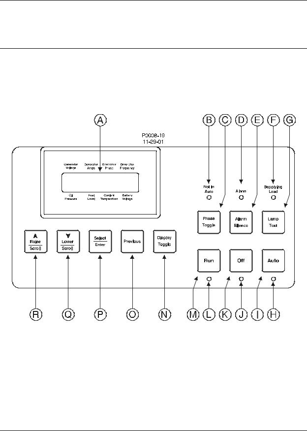
Figure 2-1 illustrates the front panel HMI of the DGC-500. Table 2-1 lists the call-outs of Figure 2-1 along with a description of each HMI component.
Figure 2-1. DGC-500 Front Panel HMI
DGC-500 HMI |
2-1 |

|
Table 2-1. DGC-500 Front Panel HMI Descriptions |
Call-Out |
Description |
|
|
A |
Liquid Crystal Display. The backlit, two line by 16 character LCD is the primary interface |
|
for metering, alarms, pre-alarms, and protective functions. The LCD has three standard |
|
display modes (Normal, Alternate, and Menu) and one optional display mode (ECU |
|
Parameters). In Normal mode, the displayed parameters correspond to one of the eight |
|
labels surrounding the LCD. In Alternate mode, the LCD displays parameters and the |
|
corresponding labels. In Menu mode, the LCD scrolls through the DGC-500 setup |
|
parameters. In the optional ECU Parameters mode, the LCD scrolls through genset |
|
parameters (metered from the ECU) and engine configuration parameters. |
|
|
B |
Not in Auto Indicator. This red LED lights when the DGC-500 is not operating in Auto |
|
mode. |
|
|
C |
Phase Toggle Pushbutton. Pressing this control scrolls through the parameters available |
|
in Normal display mode. |
|
|
D |
Alarm Indicator. This red LED lights continuously during alarm conditions and flashes |
|
during pre-alarm conditions. |
|
|
E |
Alarm Silence Pushbutton. Pressing this control resets the DGC-500 audible alarm. |
|
|
F |
Supplying Load Indicator. This green LED lights when the generator is supplying more |
|
than two percent of rated current. |
|
|
G |
Lamp Test Pushbutton. Pressing this control tests the DGC-500 indicators by exercising |
|
all LCD segments and lighting all LEDS. |
|
|
H |
Auto Mode Indicator. This green LED lights when the DGC-500 is operating in Auto mode. |
|
|
I |
Auto Pushbutton. Pressing this control places the DGC-500 in Auto mode. |
|
|
J |
Off Mode Indicator. This red LED lights when the DGC-500 is in Off mode. |
|
|
K |
Off Pushbutton. Pressing this control places the DGC-500 in Off mode. |
|
|
L |
Run Mode Indicator. This green LED lights when the DGC-500 is operating in Run mode. |
|
|
M |
Run Pushbutton. Pressing this control places the DGC-500 in Run mode. |
|
|
N |
Display Toggle Pushbutton. Pressing this control scrolls through the display modes. |
|
|
O |
Previous Pushbutton. Pressing this control scrolls through the LCD display modes. |
|
|
P |
Select/Enter Pushbutton. This control is pressed to enter menu sub-levels and select |
|
setpoints. |
|
|
Q |
Lower/Scroll Pushbutton. This control is pressed to scroll backward through menus or |
|
decrement setpoints. |
|
|
R |
Raise/Scroll Pushbutton. This control is pressed to scroll forward through menus or |
|
increment setpoints. |
REAR PANEL
All DGC-500 interface terminals are located on the rear panel. DGC-500 units have two types of terminals: quarter-inch, male, quick-connect terminals and a DB9 serial communication connector. Figure 2-2 illustrates the DGC-500 rear-panel HMI. Table 2-2 lists the call-outs of Figure 2-2 along with a description of each rearpanel HMI component.
2-2 |
DGC-500 HMI |

Figure 2-2. DGC-500 Rear Panel HMI
Table 2-2. DGC-500 Rear Panel HMI Descriptions
Call-Out |
Terminals |
Description |
|
|
|
A |
P22 |
CHASSIS GND. This terminal provides the chassis ground |
|
|
connection. The DGC-500 must be hard-wired to earth ground with |
|
|
no smaller than 12 AWG copper wire. |
|
|
|
B |
P20 (+), P21 (–) |
BATT. DGC-500 operating power is applied to these terminals. The |
|
|
DGC-500 accepts a nominal input of 12 Vdc or 24 Vdc. |
|
|
|
C |
|
Contact Sensing Terminals |
|
P35 (+), P37 (–) |
ESTOP. These terminals function as the Emergency Stop input. |
|
|
Power is removed from all DGC-500 output relays when this input is |
|
|
open. |
|
P2, P3, P4 |
PROG INPUT1, PROG INPUT2, PROG INPUT3. These three inputs |
|
|
can be independently programmed to function as an auto transfer |
|
|
switch input, single-phase override input, low coolant level input, fuel |
|
|
leak detection input, battery charger failure input, or an auxiliary |
|
|
input. The inputs accept normally-open contacts connected between |
|
|
terminals P2 (PROG INPUT1), P3 (PROG INPUT2), or P4 (PROG |
|
|
INPUT3) and terminal P21 (BATT –). |
|
|
|
DGC-500 HMI |
2-3 |

Call-Out |
Terminals |
Description |
D |
|
Transducer Terminals |
|
P39 (+), P40 (–) |
MPU. These terminals accept the output from a magnetic pickup. |
|
|
Voltage applied to this input is scaled and conditioned for use as a |
|
|
speed signal. |
|
P13 |
OIL PRESS. The output from an oil pressure transducer is applied to |
|
|
this input. A current signal lower than 5 mA can be applied between |
|
|
terminal P13 and P19 (SENDER COMM). |
|
P16 |
FUEL LEVEL. The output from a fuel level transducer is applied to |
|
|
this input. The DGC-500 supplies a transducer current signal of less |
|
|
than 30 mA to terminals P13 and P19 (SENDER COMM). |
|
P18 |
COOLANT TEMP. The output from a coolant temperature transducer |
|
|
is applied to this input. The DGC-500 supplies a transducer current |
|
|
signal of less than 5 mA to terminals P16/P18 and P19 (SENDER |
|
|
COMM). |
|
P19 |
SENDER COMM. This terminal functions as the common return line |
|
|
for all of the transducer inputs. |
E |
Voltage Sensing Terminals |
P23 |
VOLT PH A. This terminal senses the A-phase generator voltage. |
P26 |
VOLT PH B. This terminal senses the B-phase generator voltage. |
P29 |
VOLT PH C. This terminal senses the C-phase generator voltage. |
P30 |
VOLT NEUTRAL. This terminal connects to the generator Neutral in |
|
phase-to-neutral sensing applications. |
F |
|
Current Sensing Terminals |
|
P10(1/5A), P11(COM) PHASE A CT. These terminals sense the A-phase generator current. |
|
|
P12(1/5A), P14(COM) PHASE B CT. These terminals sense the B-phase generator current. |
|
|
P15(1/5A), P17(COM) PHASE C CT. These terminals sense the C-phase generator current. |
|
|
|
|
G |
P24 (+), P25(–) |
HORN. This output supplies power to an external horn. The voltage |
|
|
supplied is 24 Vdc or the battery voltage, whichever is less. A |
|
|
maximum current of 15 mAdc is available. |
|
|
|
H |
J2 |
SAE J1939 Connector. This connector is enabled on controllers with |
|
|
a style number of FXJ and provides high-speed communication |
|
|
between the DGC-500 and the ECU on an electronically controlled |
|
|
engine. |
|
|
|
I |
J1 |
RS-232 COMMUNICATION PORT. This DB9 connector uses serial |
|
|
communication to enhance DGC-500 setup. A standard serial cable |
|
|
connects the DGC-500 to a PC. |
|
|
|
J |
|
Output Contact Terminals |
|
K1-N.O., K1-COM |
CRANK. This output is closed when the DGC-500 is initiating engine |
|
|
cranking. |
|
K2-N.O., K2-COM |
FUEL. This output closes when engine cranking is initiated and |
|
|
remains closed until a stop command is received by the DGC-500. |
|
K3-N.O., K3-COM |
PRE-START. This output closes to energize the glow plugs prior to |
|
|
engine cranking. Depending on system setup, the Pre-Start output |
|
|
may open upon engine startup or stay closed during engine |
|
|
operation. |
|
P33, P34 |
PROGRAM OUTPUT1. This output closes when a user- |
|
|
programmable condition is detected by the DGC-500. |
|
P36, P38 |
PROGRAM OUTPUT2. This output closes when a user- |
|
|
programmable condition is detected by the DGC-500. |
2-4 |
DGC-500 HMI |

Call-Out |
|
Terminals |
Description |
|
|
|
|
K |
|
|
Remote Display Terminals |
|
P5 |
(+), P6 (–) |
Power. These terminals provide operating power to the optional |
|
|
|
Remote Display Panel (RDP-110). |
|
P8 |
(A), P9 (B) |
Communication. These terminals provide an RS-485 interface for |
|
|
|
communication with the optional Remote Display Panel (RDP-110). |
DGC-500 HMI |
2-5 |

SECTION 3 • FUNCTIONAL DESCRIPTION
TABLE OF CONTENTS
SECTION 3 • FUNCTIONAL DESCRIPTION . . . . . . . . . . . . . . . . . . . . . . . . . . . . . . . . . . . . . . . . . . . . . |
3-1 |
INTRODUCTION . . . . . . . . . . . . . . . . . . . . . . . . . . . . . . . . . . . . . . . . . . . . . . . . . . . . . . . . . . . . . . . |
3-1 |
DGC-500 FUNCTION BLOCKS . . . . . . . . . . . . . . . . . . . . . . . . . . . . . . . . . . . . . . . . . . . . . . . . . . . . |
3-1 |
Power Supply . . . . . . . . . . . . . . . . . . . . . . . . . . . . . . . . . . . . . . . . . . . . . . . . . . . . . . . . . . . . . . . |
3-1 |
Battery Voltage Sensing . . . . . . . . . . . . . . . . . . . . . . . . . . . . . . . . . . . . . . . . . . . . . . . . . . . . |
3-1 |
Microprocessor . . . . . . . . . . . . . . . . . . . . . . . . . . . . . . . . . . . . . . . . . . . . . . . . . . . . . . . . . . . . . . |
3-1 |
Zero Crossing Detection . . . . . . . . . . . . . . . . . . . . . . . . . . . . . . . . . . . . . . . . . . . . . . . . . . . . |
3-2 |
Analog-to-Digital Converter . . . . . . . . . . . . . . . . . . . . . . . . . . . . . . . . . . . . . . . . . . . . . . . . . . |
3-2 |
Voltage Sensing Inputs . . . . . . . . . . . . . . . . . . . . . . . . . . . . . . . . . . . . . . . . . . . . . . . . . . . . . . . |
3-2 |
Current Sensing Inputs . . . . . . . . . . . . . . . . . . . . . . . . . . . . . . . . . . . . . . . . . . . . . . . . . . . . . . . . |
3-2 |
Transducer Inputs . . . . . . . . . . . . . . . . . . . . . . . . . . . . . . . . . . . . . . . . . . . . . . . . . . . . . . . . . . . |
3-2 |
Oil Pressure . . . . . . . . . . . . . . . . . . . . . . . . . . . . . . . . . . . . . . . . . . . . . . . . . . . . . . . . . . . . . . |
3-2 |
Coolant Temperature . . . . . . . . . . . . . . . . . . . . . . . . . . . . . . . . . . . . . . . . . . . . . . . . . . . . . . . |
3-2 |
Fuel Level . . . . . . . . . . . . . . . . . . . . . . . . . . . . . . . . . . . . . . . . . . . . . . . . . . . . . . . . . . . . . . . |
3-2 |
Speed Signal Inputs . . . . . . . . . . . . . . . . . . . . . . . . . . . . . . . . . . . . . . . . . . . . . . . . . . . . . . . . . . |
3-3 |
Voltage Sensing Inputs . . . . . . . . . . . . . . . . . . . . . . . . . . . . . . . . . . . . . . . . . . . . . . . . . . . . . |
3-3 |
Magnetic Pickup Input . . . . . . . . . . . . . . . . . . . . . . . . . . . . . . . . . . . . . . . . . . . . . . . . . . . . . . |
3-3 |
Contact Input Circuitry . . . . . . . . . . . . . . . . . . . . . . . . . . . . . . . . . . . . . . . . . . . . . . . . . . . . . . . . |
3-3 |
Emergency Stop Input . . . . . . . . . . . . . . . . . . . . . . . . . . . . . . . . . . . . . . . . . . . . . . . . . . . . . . |
3-3 |
Programmable Inputs . . . . . . . . . . . . . . . . . . . . . . . . . . . . . . . . . . . . . . . . . . . . . . . . . . . . . . |
3-3 |
Front Panel HMI . . . . . . . . . . . . . . . . . . . . . . . . . . . . . . . . . . . . . . . . . . . . . . . . . . . . . . . . . . . . . |
3-3 |
LCD . . . . . . . . . . . . . . . . . . . . . . . . . . . . . . . . . . . . . . . . . . . . . . . . . . . . . . . . . . . . . . . . . . . . |
3-3 |
LEDs . . . . . . . . . . . . . . . . . . . . . . . . . . . . . . . . . . . . . . . . . . . . . . . . . . . . . . . . . . . . . . . . . . . |
3-3 |
Pushbuttons . . . . . . . . . . . . . . . . . . . . . . . . . . . . . . . . . . . . . . . . . . . . . . . . . . . . . . . . . . . . . . |
3-4 |
Remote Display Panel . . . . . . . . . . . . . . . . . . . . . . . . . . . . . . . . . . . . . . . . . . . . . . . . . . . . . . . . |
3-4 |
RS-232 Communication Port . . . . . . . . . . . . . . . . . . . . . . . . . . . . . . . . . . . . . . . . . . . . . . . . . . . |
3-4 |
SAE J1939 Interface (Optional) . . . . . . . . . . . . . . . . . . . . . . . . . . . . . . . . . . . . . . . . . . . . . . . . . |
3-4 |
Diagnostic Trouble Codes (DTCs) . . . . . . . . . . . . . . . . . . . . . . . . . . . . . . . . . . . . . . . . . . . . |
3-6 |
Horn Output . . . . . . . . . . . . . . . . . . . . . . . . . . . . . . . . . . . . . . . . . . . . . . . . . . . . . . . . . . . . . . . . |
3-7 |
Output Contacts . . . . . . . . . . . . . . . . . . . . . . . . . . . . . . . . . . . . . . . . . . . . . . . . . . . . . . . . . . . . . |
3-7 |
Pre-Start . . . . . . . . . . . . . . . . . . . . . . . . . . . . . . . . . . . . . . . . . . . . . . . . . . . . . . . . . . . . . . . . |
3-7 |
Crank . . . . . . . . . . . . . . . . . . . . . . . . . . . . . . . . . . . . . . . . . . . . . . . . . . . . . . . . . . . . . . . . . . . |
3-7 |
Fuel . . . . . . . . . . . . . . . . . . . . . . . . . . . . . . . . . . . . . . . . . . . . . . . . . . . . . . . . . . . . . . . . . . . . |
3-7 |
Programmable . . . . . . . . . . . . . . . . . . . . . . . . . . . . . . . . . . . . . . . . . . . . . . . . . . . . . . . . . . . . |
3-8 |
SOFTWARE OPERATION . . . . . . . . . . . . . . . . . . . . . . . . . . . . . . . . . . . . . . . . . . . . . . . . . . . . . . . . |
3-8 |
Power-Up Sequence . . . . . . . . . . . . . . . . . . . . . . . . . . . . . . . . . . . . . . . . . . . . . . . . . . . . . . . . . |
3-8 |
Cranking . . . . . . . . . . . . . . . . . . . . . . . . . . . . . . . . . . . . . . . . . . . . . . . . . . . . . . . . . . . . . . . . . . . |
3-8 |
Continuous Cranking . . . . . . . . . . . . . . . . . . . . . . . . . . . . . . . . . . . . . . . . . . . . . . . . . . . . . . . |
3-9 |
Cycle Cranking . . . . . . . . . . . . . . . . . . . . . . . . . . . . . . . . . . . . . . . . . . . . . . . . . . . . . . . . . . . |
3-9 |
Pre-Alarms . . . . . . . . . . . . . . . . . . . . . . . . . . . . . . . . . . . . . . . . . . . . . . . . . . . . . . . . . . . . . . . . . |
3-9 |
Low Oil Pressure . . . . . . . . . . . . . . . . . . . . . . . . . . . . . . . . . . . . . . . . . . . . . . . . . . . . . . . . . . |
3-9 |
Low Fuel . . . . . . . . . . . . . . . . . . . . . . . . . . . . . . . . . . . . . . . . . . . . . . . . . . . . . . . . . . . . . . . . |
3-9 |
High Coolant Temperature . . . . . . . . . . . . . . . . . . . . . . . . . . . . . . . . . . . . . . . . . . . . . . . . . . |
3-9 |
Low Coolant Temperature . . . . . . . . . . . . . . . . . . . . . . . . . . . . . . . . . . . . . . . . . . . . . . . . . . . |
3-9 |
Battery Overvoltage . . . . . . . . . . . . . . . . . . . . . . . . . . . . . . . . . . . . . . . . . . . . . . . . . . . . . . . . |
3-9 |
Low Battery Voltage . . . . . . . . . . . . . . . . . . . . . . . . . . . . . . . . . . . . . . . . . . . . . . . . . . . . . . . |
3-9 |
Weak Battery Voltage . . . . . . . . . . . . . . . . . . . . . . . . . . . . . . . . . . . . . . . . . . . . . . . . . . . . . |
3-10 |
Maintenance Interval . . . . . . . . . . . . . . . . . . . . . . . . . . . . . . . . . . . . . . . . . . . . . . . . . . . . . . |
3-10 |
Battery Charger Failure . . . . . . . . . . . . . . . . . . . . . . . . . . . . . . . . . . . . . . . . . . . . . . . . . . . . |
3-10 |
Fuel Level Sender Failure . . . . . . . . . . . . . . . . . . . . . . . . . . . . . . . . . . . . . . . . . . . . . . . . . . |
3-10 |
MPU Failure . . . . . . . . . . . . . . . . . . . . . . . . . . . . . . . . . . . . . . . . . . . . . . . . . . . . . . . . . . . . . |
3-10 |
DGC-500 Functional Description |
i |

Active DTC . . . . . . . . . . . . . . . . . . . . . . . . . . . . . . . . . . . . . . . . . . . . . . . . . . . . . . . . . . . . . . |
3-10 |
CAN Failure . . . . . . . . . . . . . . . . . . . . . . . . . . . . . . . . . . . . . . . . . . . . . . . . . . . . . . . . . . . . . |
3-10 |
Audible Alarm . . . . . . . . . . . . . . . . . . . . . . . . . . . . . . . . . . . . . . . . . . . . . . . . . . . . . . . . . . . . |
3-10 |
Alarms . . . . . . . . . . . . . . . . . . . . . . . . . . . . . . . . . . . . . . . . . . . . . . . . . . . . . . . . . . . . . . . . . . . . |
3-10 |
Low Oil Pressure . . . . . . . . . . . . . . . . . . . . . . . . . . . . . . . . . . . . . . . . . . . . . . . . . . . . . . . . . |
3-11 |
Low Fuel Level . . . . . . . . . . . . . . . . . . . . . . . . . . . . . . . . . . . . . . . . . . . . . . . . . . . . . . . . . . . |
3-11 |
High Coolant Temperature . . . . . . . . . . . . . . . . . . . . . . . . . . . . . . . . . . . . . . . . . . . . . . . . . . |
3-11 |
Overspeed . . . . . . . . . . . . . . . . . . . . . . . . . . . . . . . . . . . . . . . . . . . . . . . . . . . . . . . . . . . . . . |
3-11 |
Loss of Generator Voltage . . . . . . . . . . . . . . . . . . . . . . . . . . . . . . . . . . . . . . . . . . . . . . . . . . |
3-11 |
Oil Pressure Sender Failure . . . . . . . . . . . . . . . . . . . . . . . . . . . . . . . . . . . . . . . . . . . . . . . . . |
3-11 |
Coolant Temperature Sender Failure . . . . . . . . . . . . . . . . . . . . . . . . . . . . . . . . . . . . . . . . . . |
3-11 |
Speed Source Failure . . . . . . . . . . . . . . . . . . . . . . . . . . . . . . . . . . . . . . . . . . . . . . . . . . . . . . |
3-11 |
CAN Failure . . . . . . . . . . . . . . . . . . . . . . . . . . . . . . . . . . . . . . . . . . . . . . . . . . . . . . . . . . . . . |
3-12 |
DISPLAY OPERATION . . . . . . . . . . . . . . . . . . . . . . . . . . . . . . . . . . . . . . . . . . . . . . . . . . . . . . . . . . |
3-12 |
Normal Mode . . . . . . . . . . . . . . . . . . . . . . . . . . . . . . . . . . . . . . . . . . . . . . . . . . . . . . . . . . . . . . . |
3-12 |
Firmware Version . . . . . . . . . . . . . . . . . . . . . . . . . . . . . . . . . . . . . . . . . . . . . . . . . . . . . . . . . |
3-12 |
Alternate Mode . . . . . . . . . . . . . . . . . . . . . . . . . . . . . . . . . . . . . . . . . . . . . . . . . . . . . . . . . . . . . |
3-12 |
Diagnostic Trouble Codes (DTCs) . . . . . . . . . . . . . . . . . . . . . . . . . . . . . . . . . . . . . . . . . . . . |
3-12 |
ECU Parameters Mode . . . . . . . . . . . . . . . . . . . . . . . . . . . . . . . . . . . . . . . . . . . . . . . . . . . . . . . |
3-14 |
Engine Configuration Parameters . . . . . . . . . . . . . . . . . . . . . . . . . . . . . . . . . . . . . . . . . . . . |
3-16 |
Menu Mode . . . . . . . . . . . . . . . . . . . . . . . . . . . . . . . . . . . . . . . . . . . . . . . . . . . . . . . . . . . . . . . . |
3-17 |
Menu 1 . . . . . . . . . . . . . . . . . . . . . . . . . . . . . . . . . . . . . . . . . . . . . . . . . . . . . . . . . . . . . . . . . |
3-17 |
Menu 2 . . . . . . . . . . . . . . . . . . . . . . . . . . . . . . . . . . . . . . . . . . . . . . . . . . . . . . . . . . . . . . . . . |
3-17 |
Menu 3 . . . . . . . . . . . . . . . . . . . . . . . . . . . . . . . . . . . . . . . . . . . . . . . . . . . . . . . . . . . . . . . . . |
3-17 |
Menu 4 . . . . . . . . . . . . . . . . . . . . . . . . . . . . . . . . . . . . . . . . . . . . . . . . . . . . . . . . . . . . . . . . . |
3-17 |
Exiting Menu Mode . . . . . . . . . . . . . . . . . . . . . . . . . . . . . . . . . . . . . . . . . . . . . . . . . . . . . . . . |
3-17 |
Changing Settings . . . . . . . . . . . . . . . . . . . . . . . . . . . . . . . . . . . . . . . . . . . . . . . . . . . . . . . . . . . |
3-22 |
Key Code . . . . . . . . . . . . . . . . . . . . . . . . . . . . . . . . . . . . . . . . . . . . . . . . . . . . . . . . . . . . . . . . . . |
3-22 |
ENGINE CONTROL UNIT (ECU) SUPPORT . . . . . . . . . . . . . . . . . . . . . . . . . . . . . . . . . . . . . . . . . |
3-22 |
Enabling ECU Support . . . . . . . . . . . . . . . . . . . . . . . . . . . . . . . . . . . . . . . . . . . . . . . . . . . . . . . |
3-22 |
ECU Constraints . . . . . . . . . . . . . . . . . . . . . . . . . . . . . . . . . . . . . . . . . . . . . . . . . . . . . . . . . . . . |
3-23 |
The DGC-500 Solution . . . . . . . . . . . . . . . . . . . . . . . . . . . . . . . . . . . . . . . . . . . . . . . . . . . . . |
3-23 |
Alarms and Pre-Alarms . . . . . . . . . . . . . . . . . . . . . . . . . . . . . . . . . . . . . . . . . . . . . . . . . . . . . . . |
3-23 |
Fuel Solenoid Relay . . . . . . . . . . . . . . . . . . . . . . . . . . . . . . . . . . . . . . . . . . . . . . . . . . . . . . . . . |
3-23 |
Display Values (ECU Support Enabled) . . . . . . . . . . . . . . . . . . . . . . . . . . . . . . . . . . . . . . . . . . |
3-24 |
ECUs with an External Fuel Solenoid . . . . . . . . . . . . . . . . . . . . . . . . . . . . . . . . . . . . . . . . . . . . |
3-24 |
STATE MACHINES . . . . . . . . . . . . . . . . . . . . . . . . . . . . . . . . . . . . . . . . . . . . . . . . . . . . . . . . . . . . . |
3-24 |
System Configuration . . . . . . . . . . . . . . . . . . . . . . . . . . . . . . . . . . . . . . . . . . . . . . . . . . . . . . . . |
3-25 |
Operating States . . . . . . . . . . . . . . . . . . . . . . . . . . . . . . . . . . . . . . . . . . . . . . . . . . . . . . . . . . . . |
3-25 |
State Transitions . . . . . . . . . . . . . . . . . . . . . . . . . . . . . . . . . . . . . . . . . . . . . . . . . . . . . . . . . . . . |
3-25 |
Normal Program Control . . . . . . . . . . . . . . . . . . . . . . . . . . . . . . . . . . . . . . . . . . . . . . . . . . . . . . |
3-25 |
ECU Power Support Program Control . . . . . . . . . . . . . . . . . . . . . . . . . . . . . . . . . . . . . . . . . . . . |
3-26 |
Initial State - Power Up/Reset . . . . . . . . . . . . . . . . . . . . . . . . . . . . . . . . . . . . . . . . . . . . . . . . . . |
3-26 |
Ready State . . . . . . . . . . . . . . . . . . . . . . . . . . . . . . . . . . . . . . . . . . . . . . . . . . . . . . . . . . . . . . . . |
3-27 |
Going to Off or Auto-Off . . . . . . . . . . . . . . . . . . . . . . . . . . . . . . . . . . . . . . . . . . . . . . . . . . . . |
3-27 |
Pulsing State . . . . . . . . . . . . . . . . . . . . . . . . . . . . . . . . . . . . . . . . . . . . . . . . . . . . . . . . . . . . . . . |
3-28 |
Connecting State . . . . . . . . . . . . . . . . . . . . . . . . . . . . . . . . . . . . . . . . . . . . . . . . . . . . . . . . . . . . |
3-28 |
Pre-Start State . . . . . . . . . . . . . . . . . . . . . . . . . . . . . . . . . . . . . . . . . . . . . . . . . . . . . . . . . . . . . . |
3-29 |
Cranking State . . . . . . . . . . . . . . . . . . . . . . . . . . . . . . . . . . . . . . . . . . . . . . . . . . . . . . . . . . . . . . |
3-29 |
Resting State . . . . . . . . . . . . . . . . . . . . . . . . . . . . . . . . . . . . . . . . . . . . . . . . . . . . . . . . . . . . . . . |
3-30 |
Running State . . . . . . . . . . . . . . . . . . . . . . . . . . . . . . . . . . . . . . . . . . . . . . . . . . . . . . . . . . . . . . |
3-30 |
Cooling State . . . . . . . . . . . . . . . . . . . . . . . . . . . . . . . . . . . . . . . . . . . . . . . . . . . . . . . . . . . . . . . |
3-31 |
Shutting Down State . . . . . . . . . . . . . . . . . . . . . . . . . . . . . . . . . . . . . . . . . . . . . . . . . . . . . . . . . |
3-31 |
Alarm State . . . . . . . . . . . . . . . . . . . . . . . . . . . . . . . . . . . . . . . . . . . . . . . . . . . . . . . . . . . . . . . . |
3-32 |
ii |
DGC-500 Functional Description |

Figures |
|
Figure 3-1. DGC-500 Function Block Diagram . . . . . . . . . . . . . . . . . . . . . . . . . . . . . . . . . . . . . . . . . . . . |
3-1 |
Figure 3-2. Display Mode Navigation . . . . . . . . . . . . . . . . . . . . . . . . . . . . . . . . . . . . . . . . . . . . . . . . . . |
3-12 |
Figure 3-3. Alternate Mode Navigation . . . . . . . . . . . . . . . . . . . . . . . . . . . . . . . . . . . . . . . . . . . . . . . . . |
3-13 |
Figure 3-4. Lamp Status Screen . . . . . . . . . . . . . . . . . . . . . . . . . . . . . . . . . . . . . . . . . . . . . . . . . . . . . . |
3-13 |
Figure 3-5. DTC Screen Example . . . . . . . . . . . . . . . . . . . . . . . . . . . . . . . . . . . . . . . . . . . . . . . . . . . . . |
3-14 |
Figure 3-6. ECU Parameters Navigation . . . . . . . . . . . . . . . . . . . . . . . . . . . . . . . . . . . . . . . . . . . . . . . . |
3-15 |
Figure 3-7. Engine Configuration Menu Navigation . . . . . . . . . . . . . . . . . . . . . . . . . . . . . . . . . . . . . . . |
3-16 |
Figure 3-8. Menu Mode Navigation . . . . . . . . . . . . . . . . . . . . . . . . . . . . . . . . . . . . . . . . . . . . . . . . . . . . |
3-17 |
Figure 3-9. Menu 1 Navigation . . . . . . . . . . . . . . . . . . . . . . . . . . . . . . . . . . . . . . . . . . . . . . . . . . . . . . . |
3-18 |
Figure 3-10. Menu 2 Navigation . . . . . . . . . . . . . . . . . . . . . . . . . . . . . . . . . . . . . . . . . . . . . . . . . . . . . . |
3-19 |
Figure 3-11. Menu 3 Navigation . . . . . . . . . . . . . . . . . . . . . . . . . . . . . . . . . . . . . . . . . . . . . . . . . . . . . . |
3-20 |
Figure 3-12. Menu 4 Navigation . . . . . . . . . . . . . . . . . . . . . . . . . . . . . . . . . . . . . . . . . . . . . . . . . . . . . . |
3-21 |
Figure 3-13. Setting Change Example . . . . . . . . . . . . . . . . . . . . . . . . . . . . . . . . . . . . . . . . . . . . . . . . . |
3-22 |
Figure 3-14. Screens Shown Following Unsuccessful Information Update from ECU . . . . . . . . . . . . . |
3-24 |
Figure 3-15. Normal Program Control Diagram . . . . . . . . . . . . . . . . . . . . . . . . . . . . . . . . . . . . . . . . . . |
3-26 |
Figure 3-16. ECU Power Support Program Control Diagram . . . . . . . . . . . . . . . . . . . . . . . . . . . . . . . . |
3-26 |
Figure 3-17. Power Up/Reset State Diagram . . . . . . . . . . . . . . . . . . . . . . . . . . . . . . . . . . . . . . . . . . . . |
3-27 |
Figure 3-18. Ready State Diagram . . . . . . . . . . . . . . . . . . . . . . . . . . . . . . . . . . . . . . . . . . . . . . . . . . . . |
3-28 |
Figure 3-19. Pulsing State Diagram . . . . . . . . . . . . . . . . . . . . . . . . . . . . . . . . . . . . . . . . . . . . . . . . . . . |
3-28 |
Figure 3-20. Connecting State Diagram . . . . . . . . . . . . . . . . . . . . . . . . . . . . . . . . . . . . . . . . . . . . . . . . |
3-29 |
Figure 3-21. Pre-Start State Diagram . . . . . . . . . . . . . . . . . . . . . . . . . . . . . . . . . . . . . . . . . . . . . . . . . . |
3-29 |
Figure 3-22. Cranking State Diagram . . . . . . . . . . . . . . . . . . . . . . . . . . . . . . . . . . . . . . . . . . . . . . . . . . |
3-30 |
Figure 3-23. Resting State Diagram . . . . . . . . . . . . . . . . . . . . . . . . . . . . . . . . . . . . . . . . . . . . . . . . . . . |
3-30 |
Figure 3-24. Running State Diagram . . . . . . . . . . . . . . . . . . . . . . . . . . . . . . . . . . . . . . . . . . . . . . . . . . . |
3-31 |
Figure 3-25. Cooling State Diagram . . . . . . . . . . . . . . . . . . . . . . . . . . . . . . . . . . . . . . . . . . . . . . . . . . . |
3-31 |
Figure 3-26. Shutting down State Diagram . . . . . . . . . . . . . . . . . . . . . . . . . . . . . . . . . . . . . . . . . . . . . . |
3-32 |
Figure 3-27. Alarm State Diagram . . . . . . . . . . . . . . . . . . . . . . . . . . . . . . . . . . . . . . . . . . . . . . . . . . . . . |
3-32 |
Tables |
|
Table 3-1. ECU Parameters Obtained from CAN Interface . . . . . . . . . . . . . . . . . . . . . . . . . . . . . . . . . . . |
3-5 |
Table 3-2. Engine Configuration Parameters Obtained from CAN Interface . . . . . . . . . . . . . . . . . . . . . . |
3-6 |
Table 3-3. Diagnostic Information Obtained Over the CAN Interface . . . . . . . . . . . . . . . . . . . . . . . . . . . |
3-7 |
DGC-500 Functional Description |
iii |
SECTION 3 • FUNCTIONAL DESCRIPTION
INTRODUCTION
This section describes how the DGC-500 functions and explains its operating features. A detailed description of each function block is provided in the paragraphs under the heading of DGC-500 Function Blocks.
DGC-500 operating features are described under the heading of Software Operation.
DGC-500 FUNCTION BLOCKS
To ease understanding, DGC-500 functions are illustrated in the block diagram of Figure 3-1. The following paragraphs describe each function in detail.
Figure 3-1. DGC-500 Function Block Diagram
Power Supply
The internal, switch-mode power supply uses the applied battery voltage to generate operating power for the internal circuitry of the DGC-500. The power supply accepts a nominal battery voltage of 12 or 24 Vdc and has an operating range of 8 to 32 Vdc. Battery voltage is applied to terminals P20 (+) and P21 (–).
Battery Voltage Sensing
Voltage applied to the power supply is filtered and reduced to a suitable level for sensing by the microprocessor.
Microprocessor
The microprocessor controls the overall functionality of the DGC-500 and makes decisions based on programming and system inputs.
DGC-500 Functional Description |
3-1 |

Circuits relating to the microprocessor inputs are described in the following paragraphs.
Zero Crossing Detection
The zero crossing of A-phase to B-phase line voltage is detected and used to calculate the generator frequency.
Analog-to-Digital Converter
Scaled and conditioned signals representing the sensing voltage, sensing current, coolant temperature, fuel level, oil pressure, and battery voltage are digitized by the microprocessor’s 10-bit analog-to-digital converter. The digitized information is stored in random access memory (RAM) and used by the microprocessor for all metering and protection functions.
Voltage Sensing Inputs
Generator voltages applied to the voltage sensing inputs are scaled to levels suitable for use by the internal circuitry. Voltage sensing configuration is menu-selectable.
The voltage sensing inputs accept a maximum voltage of 576 Vrms, line-to-line. Sensing voltage is applied to terminals P23 (A-phase), P26 (B-phase), P29 (C-phase), and P30 (Neutral).
Current Sensing Inputs
Generator currents are sensed and scaled to values suitable for use by the internal circuitry. Isolation is provided by internal current transformers (CTs).
DGC-500–X1 units accept a maximum current value of 1 Aac. DGC-500–X5 units accept a maximum current value of 5 Aac. Sensing current is applied to terminals P10 and P11 (A-phase), P12 and P14 (B-phase), and P15 and P17 (C-phase).
Transducer Inputs
Programmable transducer inputs of the give the DGC-500 user the flexibility to select the transducer to be used in an application. Information about programming the transducer inputs is provided in Section 6,
BESTCOMS Software.
Oil Pressure
A current of less than 30 milliamperes is provided to the oil pressure transducer. The developed voltage is measured and scaled for use by the internal circuitry. Oil pressure transducers that are compatible with the DGC-500 include Isspro model R8919, Stewart-Warner models 279BF, 279C, 411K, and 411M, and VDO models 360025 and 360811. Other senders may be used. BESTCOMS software allows for the programming of sender characteristics. See Section 4, BESTCOMS Software for more information.
Oil pressure transducer connections are provided at terminals P13 and P19 (sender common).
Coolant Temperature
A current of less than 1.2 milliamperes is provided to the coolant temperature transducer. The developed voltage is measured and scaled for use by the internal circuitry. Coolant temperature transducers that are compatible with the DGC-500 include Isspro model R8959 and Stewart-Warner 334-P. Other senders may be used. BESTCOMS software allows for the programming of sender characteristics. See Section 4, BESTCOMS Software for more information.
Coolant temperature transducer connections are provided at terminals P18 and P19 (sender common).
Fuel Level
A current of less than 5 milliamperes is provided to the fuel level transducer. The developed voltage is measured and scaled for use by the internal circuitry. An open circuit or short circuit across the fuel level transducer terminals will cause the DGC-500 to indicate a failed fuel level transducer. Fuel level transducers that are compatible with the DGC-500 include Isspro model R8925. Other senders may be used. BESTCOMS
3-2 |
DGC-500 Functional Description |

software allows for the programming of sender characteristics. See Section 4, BESTCOMS Software for more information.
Fuel level transducer connections are provided at terminals P16 and P19 (sender common).
Speed Signal Inputs
The DGC-500 uses signals from the voltage sensing inputs and magnetic pickup input to detect machine speed.
Voltage Sensing Inputs
Generator voltage applied to the DGC-500 voltage sensing inputs is used to measure frequency and can be used to measure machine speed.
Sensing voltage is applied to terminals P23 (A-phase), P26 (B-phase), P29 (C-phase), and P30 (Neutral).
Magnetic Pickup Input
The voltage received from the magnetic pickup is scaled and conditioned for use by the internal circuitry as a speed signal source.
Magnetic pickup connections are provided at terminals P39 (+) and P40 (–).
Contact Input Circuitry
The DGC-500 has four contact sensing inputs: Emergency Stop and three programmable inputs.
Emergency Stop Input
This input accepts Form A, dry contacts. An open circuit at this continuously monitored input initiates an emergency stop. An emergency stop removes operating power from all DGC-500 output relays.
Emergency stop contact connections are provided at terminals P35 and P37.
Programmable Inputs
Each programmable input (PROG INPUT1, PROG INPUT2, and PROG INPUT3) can be independently configured as an auto transfer switch input, single-phase override input, low coolant level input, fuel leak detection input, battery charger failure input, or an auxiliary input. By default, each programmable input is disabled.
The programmable inputs accept normally open, Form A contacts. A contact is connected between a programmable input and the negative side of the battery voltage. Through BESTCOMS software, each programmable contact input can be assigned a name (eight characters, maximum) and configured as an alarm input, a pre-alarm input, or neither. The default names for the inputs are AUX IN 1, AUX IN 2, and AUX IN 3. When a programmable contact input is closed, the front panel display shows the name of the closed input if it was programmed as an alarm or pre-alarm input. Alarm inputs are annunciated through the Normal display mode screens of the front panel. Pre-alarm inputs are annunciated through the Alternate display mode screens of the front panel. If neither is programmed, no indication is given. Programming an input as neither is useful when a programmable input is used to close one of the DGC-500's programmable outputs.
Connections for the programmable inputs are provided at terminals P2 (PROG INPUT1), P3 (PROG INPUT2), and P4 (PROG INPUT3). The negative side of the battery voltage (terminal P21) serves as the return connection for the programmable inputs.
Front Panel HMI
The front panel HMI provides a convenient interface for viewing system parameters and for controlling the DGC-500 and generator operation. Front panel HMI components include an LCD (liquid crystal display), LEDS (light emitting diodes), and pushbuttons.
LCD
The backlit LCD provides metering, pre-alarm, and alarm information. Detailed information about the LCD is provided in the Software Operation sub-section.
DGC-500 Functional Description |
3-3 |

LEDs
The LEDs indicate pre-alarm and alarm conditions along with DGC-500 status and generator status.
Pushbuttons
The pushbuttons are used to scroll through and select parameters displayed on the LCD, change setpoints, start and stop the generator, and reset alarms.
Remote Display Panel
Applications that require remote annunciation can use Basler Electric’s Remote Display Panel, RDP-110. Using the RDP-110 with the DGC-500 meets the requirements of NFPA Standard 110. The RDP-110 uses a standard, two-terminal RS-485 interface to communicate with the DGC-500 and receives operating power from the DGC-500. Remote indication of many pre-alarm and alarm conditions is provided by the RDP-110.
The following pre-alarm conditions are indicated by LEDs on the RDP-110 front panel.
C |
Low coolant temperature |
C |
Weak battery |
C |
High coolant temperature |
C |
Battery overvoltage |
C |
Low oil pressure |
C |
Battery charger failure |
CLow fuel level
The following alarm conditions are indicated by LEDs and an audible alarm on the RDP-110 front panel.
C |
Low coolant level |
C |
Overspeed |
C |
High coolant temperature |
C |
Emergency stop |
C |
Low oil pressure |
C Fuel leak/fuel level sender failure |
|
C |
Overcrank |
C Engine sender unit failure |
|
Additionally, the RDP-110 indicates when the DGC-500 is not operating in Auto mode and when the generator is supplying load.
For more information about the RDP-110, request Basler Product Bulletin SNE-2.
RS-232 Communication Port
The communication port, located on the rear panel, consists of an optically isolated female DB-9 connector. The RS-232 connector serves as a communication interface for enhances DGC-500 setup. Communication requires a standard 9-pin serial communication cable connected between the RS-232 communication port and a PC operating with BESTCOMS-DGC500-32. BESTCOMS is a Windows® based communication software package that is supplied with the DGC-500. A detailed description of BESTCOMS is provided in Section 4,
BESTCOMS Software for Windows® .
SAE J1939 Interface (Optional)
A Controller Area Network (CAN) is a standard interface that allows communication between multiple controllers on a common network using a standard message protocol. DGC-500 controllers with a style number of FXJ have a CAN interface that supports the SAE J1939 message protocol.
Applications using an engine-driven generator set controlled by a DGC-500 may also have an Engine Control Unit (ECU). The CAN interface allows the ECU and DGC-500 to communicate. The ECU reports operating information to the DGC-500 through the CAN interface. Operating parameters and diagnostic information, if supported by the ECU, are decoded and displayed for monitoring.
The primary use of the CAN interface is to obtain engine operating parameters for monitoring speed, coolant temperature, oil pressure, coolant level, and engine hours without the need for direct connection to individual senders. Table 3-1 lists the ECU parameters and Table 3-2 lists the engine configuration parameters supported by the DGC-500 CAN interface. These parameters are transmitted via the CAN interface at preset intervals. The columns labeled Update Rate show the parameter transmission rates. This information can also be transmitted upon user request.
3-4 |
DGC-500 Functional Description |

Table 3-1. ECU Parameters Obtained from CAN Interface
|
Metric |
English |
Update |
Decimal |
t |
ECU Parameter |
Units |
Units |
Rate |
Place |
SPN |
|
|
|
|
|
|
Throttle (accelerator pedal) position |
% |
% |
50 ms |
10th |
91 |
|
|
|
|
|
|
Percent load at current rpm |
% |
% |
50 ms |
none |
92 |
|
|
|
|
|
|
Actual engine percent torque |
% |
% |
engine |
none |
513 |
|
|
|
speed |
|
|
|
|
|
dependent |
|
|
|
|
|
|
|
|
Engine speed |
rpm |
rpm |
engine |
none |
190 |
|
|
|
speed |
|
|
|
|
|
dependent |
|
|
|
|
|
|
|
|
Injection control pressure |
MPa |
psi |
500 ms |
none |
164 |
|
|
|
|
|
|
Injector Metering Rail Pressure |
Mpa |
psi |
500 ms |
none |
157 |
|
|
|
|
|
|
Total engine hours |
hours |
hours |
requested |
100th |
247 |
|
|
|
1.5 s |
|
|
|
|
|
|
|
|
Trip fuel |
liters |
gallons |
requested |
none |
182 |
|
|
|
1.5 s |
|
|
|
|
|
|
|
|
Total fuel used |
liters |
gallons |
requested |
none |
250 |
|
|
|
1.5 s |
|
|
|
|
|
|
|
|
Engine coolant temperature |
°C |
°F |
1 s |
none |
110 |
|
|
|
|
|
|
Fuel temperature |
°C |
°F |
1 s |
none |
174 |
|
|
|
|
|
|
Engine oil temperature |
°C |
°F |
1 s |
10th |
175 |
|
|
|
|
|
|
Engine intercooler temperature |
°C |
°F |
1 s |
none |
52 |
|
|
|
|
|
|
Fuel delivery pressure |
kPa |
psi |
500 ms |
10th |
94 |
|
|
|
|
|
|
Engine oil level |
% |
% |
500 ms |
10th |
98 |
|
|
|
|
|
|
Engine oil pressure |
kPa |
psi |
500 ms |
10th |
100 |
|
|
|
|
|
|
Coolant pressure |
kPa |
psi |
500 ms |
10th |
109 |
|
|
|
|
|
|
Coolant level |
% |
% |
500 ms |
10th |
111 |
Fuel rate |
liter/hr |
gal/hr |
100 ms |
100th |
183 |
|
|
|
|
|
|
Barometric pressure |
kPa |
psi |
1 s |
10th |
108 |
|
|
|
|
|
|
Ambient air temperature |
°C |
°F |
1 s |
10th |
171 |
|
|
|
|
|
|
Air inlet temperature |
°C |
°F |
1 s |
none |
172 |
|
|
|
|
|
|
Boost pressure |
kPa |
psi |
500 ms |
none |
102 |
|
|
|
|
|
|
Intake manifold temperature |
°C |
°F |
500 ms |
none |
105 |
|
|
|
|
|
|
Air filter differential pressure |
kPa |
psi |
500 ms |
100th |
107 |
|
|
|
|
|
|
Exhaust gas temperature |
°C |
°F |
500 ms |
10th |
173 |
|
|
|
|
|
|
Battery voltage |
Vdc |
Vdc |
1 s |
10th |
168 |
|
|
|
|
|
|
Switched battery voltage (at ECU) |
Vdc |
Vdc |
1 s |
10th |
158 |
tSPN is Suspect Parameter Number
DGC-500 Functional Description |
3-5 |

Table 3-2. Engine Configuration Parameters Obtained from CAN Interface
t |
Metric |
English |
Update |
Decimal |
|
Engine Configuration Parameter |
Units |
Units |
Rate |
Place |
SPN |
|
|
|
|
|
|
Engine speed at idle point 1 |
rpm |
rpm |
5 s |
none |
188 |
|
|
|
|
|
|
Percent torque at idle point 1 |
% |
% |
5 s |
none |
539 |
|
|
|
|
|
|
Engine speed at point 2 |
rpm |
rpm |
5 s |
none |
528 |
|
|
|
|
|
|
Percent torque at point 2 |
% |
% |
5 s |
none |
540 |
|
|
|
|
|
|
Engine speed at point 3 |
rpm |
rpm |
5 s |
none |
529 |
|
|
|
|
|
|
Percent torque at point 3 |
% |
% |
5 s |
none |
541 |
|
|
|
|
|
|
Engine speed at point 4 |
rpm |
rpm |
5 s |
none |
530 |
|
|
|
|
|
|
Percent torque at point 4 |
% |
% |
5 s |
none |
542 |
|
|
|
|
|
|
Engine speed at point 5 |
rpm |
rpm |
5 s |
none |
531 |
|
|
|
|
|
|
Percent torque at point 5 |
% |
% |
5 s |
none |
543 |
|
|
|
|
|
|
Engine speed at high idle point 6 |
rpm |
rpm |
5 s |
none |
532 |
|
|
|
|
|
|
Gain (KP) of endspeed governor |
%/rpm |
%/rpm |
5 s |
100th |
545 |
|
|
|
|
|
|
Reference engine torque |
Nm |
ft-lb |
5 s |
none |
544 |
|
|
|
|
|
|
Maximum momentary engine |
rpm |
rpm |
5 s |
none |
533 |
override speed point 7 |
|
|
|
|
|
|
|
|
|
|
|
Maximum momentary engine |
seconds |
seconds |
5 s |
10th |
534 |
override time limit |
|
|
|
|
|
|
|
|
|
|
|
Requested speed control range |
rpm |
rpm |
5 s |
none |
535 |
lower limit |
|
|
|
|
|
|
|
|
|
|
|
Requested speed control range |
rpm |
rpm |
5 s |
none |
536 |
upper limit |
|
|
|
|
|
|
|
|
|
|
|
Requested torque control range |
% |
% |
5 s |
none |
537 |
lower limit |
|
|
|
|
|
|
|
|
|
|
|
Requested torque control range |
% |
% |
5 s |
none |
538 |
upper limit |
|
|
|
|
|
tPress the Select pushbutton to enter the Engine Configuration submenu. Press the Previous pushbutton to exit the submenu.
CAUTION
When the CAN interface is enabled, the DGC-500 will ignore the following sender inputs: oil pressure, coolant temperature, and magnetic pickup.
Diagnostic Trouble Codes (DTCs)
The DGC-500 obtains the diagnostic condition of the transmitting electronic components. The DGC-500 will receive an unsolicited message of a currently active diagnostic trouble code (DTC). Previously active DTCs are available upon request. Active and previously active DTCs can be cleared on request. Table 3-3 lists the diagnostic information that the DGC-500 obtains over the CAN interface.
3-6 |
DGC-500 Functional Description |

Table 3-3. Diagnostic Information Obtained Over the CAN Interface
|
Transmission |
Parameter |
Repetition Rate |
|
|
Active diagnostic trouble code |
1 s |
|
|
Lamp status |
1 s |
|
|
Previously active diagnostic trouble code |
on request |
|
|
Request to clear previously active DTCs |
on request |
|
|
Request to clear active DTCs |
on request |
|
|
DTCs are reported in coded diagnostic information that includes the Suspect Parameter Number (SPN), Failure Mode Identifier (FMI), and Occurrence Count (OC). All parameters have an SPN and are used to display or identify the items for which diagnostics are being reported. The FMI defines the type of failure detected in the subsystem identified by an SPN. The reported problem may not be an electrical failure but a subsystem condition needing to be reported to an operator or technician. The OC contains the number of times that a fault has gone from active to previously active.
Horn Output
This output connects to a user-supplied audible signal device. A change in operating status or an alarm condition energizes the horn output continuously and a pre-alarm condition pulses the horn output on and off. The annunciation continues until the condition subsides or until the front-panel Alarm Silence pushbutton is pressed.
The horn output supplies 15 mAdc maximum at the lesser of 24 Vdc or the battery voltage level. A horn compatible with the DGC-500 is available from Basler Electric as part number 29760. Horn output connections are located at terminals P24 (+) and P25 (–).
Output Contacts
All output contacts are electrically isolated from each other and from the DGC-500 internal circuitry. Output contact operation is controlled by the operating mode of the DGC-500 and the system. The output contacts are also affected by the status of the Emergency Stop contact input. When the Emergency Stop contact input is open (emergency stop condition), all output contacts open. When the Emergency Stop contact input is closed, all output contacts operate normally.
Five output contacts are available: Pre-Start, Engine Crank, Fuel Solenoid, and two Programmable output contacts.
Pre-Start
This output closes to energize the engine glow plugs. The Pre-Start output can be programmed to close up to 30 seconds prior to engine cranking. The Pre-Start output can also be programmed to open upon engine startup or remain closed as long as the engine is operating.
Crank
This output closes when engine cranking is initiated by the DGC-500. The length of time that the contacts remain closed is determined by the cranking style selected (either continuous or cycle). Cranking continues until the magnetic pickup or generator frequency indicates that the engine has started.
Fuel
This output closes when engine cranking is initiated by the DGC-500. The Fuel output remains closed until an off command is issued and the engine stops.
DGC-500 Functional Description |
3-7 |

Programmable
Two programmable outputs (PROGRAM OUTPUT1, 2) can be user-configured to close for a variety of conditions.
Either programmable output can be programmed to close during any of the following operating conditions.
CCooldown timer active
CEPS supplying load
CPre-start condition in effect
CSwitch not in Auto
CProgrammable Input 1 closed
CProgrammable Input 2 closed
CProgrammable Input 3 closed
Either of the programmable outputs can be configured to give a pre-alarm indication by closing during any of the following pre-alarm conditions.
C |
Battery charger failure |
C |
Low coolant level |
C |
Battery overvoltage |
C |
Low coolant temperature |
C |
Fuel leak |
C |
Low fuel |
C |
Fuel leak/sender failure |
C |
Low oil pressure |
C |
High coolant temperature |
C |
Scheduled maintenance due |
C |
Low battery voltage |
C |
Weak battery voltage |
Either of the programmable outputs can be configured to give an alarm indication by closing during any of the following alarm conditions.
C |
Battery charger |
C |
Low fuel |
C Coolant temperature sender failure |
C |
Low oil pressure |
|
C |
Emergency stop |
C MPU speed sender failure |
|
C |
Fuel leak |
C Oil pressure sender failure |
|
C |
High coolant temperature |
C |
Overcrank |
C Loss of voltage sender failure |
C |
Overspeed |
|
CLow coolant level
SOFTWARE OPERATION
Embedded software controls all aspects of DGC-500 operation. DGC-500 software controls power-up initiation, HMI configuration, engine cranking, contact input monitoring, fault detection and annunciation, system parameter monitoring, output contact control, and communication.
Power-Up Sequence
When battery power is applied, the DGC-500 initiates a power-up sequence. During power-up, DGC-500 memory is checked and the LCD displays the embedded software version. Then, all configuration data stored in nonvolatile EEPROM (electronically erasable programmable read-only memory) is brought into main memory and the DGC-500 begins operating in Normal mode. When operating in Normal mode, all enabled functions are active and all inputs are monitored.
NOTE
The run-time counter and maintenance timer values are updated in volatile memory once per minute. Updated values are saved to nonvolatile memory when the Auto/Off/Run mode of operation is changed. Additionally, while the engine is running, the run-time counter value is saved to nonvolatile memory every 15 minutes. If the battery power source fails during DGC500 operation, these values are not updated and the changes made after the last save operation to nonvolatile memory are irretrievably lost.
Cranking
The DGC-500 can be programmed for either continuous engine cranking or cycle engine cranking.
3-8 |
DGC-500 Functional Description |

Continuous Cranking
If desired, engine cranking can be delayed from zero to 30 seconds after initiating engine startup. When continuous engine cranking is initiated, cranking is sustained for a user-adjustable period of one to 60 seconds. A crank disconnect limit setting (10 to 100% of nominal engine speed) selects the desired engine speed above which cranking is terminated.
Cycle Cranking
If desired, engine cranking can be delayed from zero to 30 seconds after initiating engine startup. When cycle engine cranking is initiated, five to 15 seconds of cranking is followed by an equal number of seconds of rest. A maximum of seven cranking cycles (five cycles for NFPA compliant units) are allowed by the DGC-500. A crank disconnect limit setting (10 to 100% of nominal engine speed) selects the desired engine speed above which cranking is terminated.
Pre-Alarms
A pre-alarm is annunciated when a condition programmed to trigger a pre-alarm is met. When a pre-alarm condition exists, the front panel Alarm indicator flashes on and off and the Horn output (if enabled through BESTCOMS) alternates between an energized and de-energized state. The audible alarm is reset by pressing the front panel Alarm Silence pushbutton.
Active pre-alarms for oil pressure, fuel level, coolant temperature, and battery voltage are displayed on the main display of the LCD. The LCD annunciates an active pre-alarm by alternating between the current parameter value and a blacked-out field for that value. All other pre-alarms are displayed in sequence through the alternate mode display.
Each DGC-500 pre-alarm is described in the following paragraphs.
Low Oil Pressure
A low oil pressure pre-alarm occurs when the engine oil pressure decreases below the setpoint programmed in BESTCOMS. The low oil pressure pre-alarm has a setting range of 3 to 150 psi or 20 to 1,035 kPa. A 10 second activation time delay prevents low oil pressure annunciation during engine startup.
Low Fuel
A low fuel pre-alarm occurs when the fuel level decreases below the setpoint programmed in BESTCOMS. The low fuel pre-alarm has a setting range of 10 to 100 percent.
High Coolant Temperature
A high coolant temperature pre-alarm occurs when the engine coolant temperature exceeds the setpoint programmed in BESTCOMS. The high coolant temperature pre-alarm has a setting range of 100 to 280°F or 38 to 138°C. A 60 second activation time delay prevents high coolant temperature annunciation during system startup.
Low Coolant Temperature
A low coolant temperature pre-alarm occurs when the engine coolant temperature decreases below the setpoint programmed in BESTCOMS. The low coolant temperature pre-alarm has a setting range of 50 to 100°F or 10 to 38°C.
Battery Overvoltage
A battery overvoltage pre-alarm occurs when the battery overvoltage pre-alarm function is enabled in BESTCOMS and the battery voltage level exceeds 30 Vdc for 24 Vdc system or 15 Vdc for 12 Vdc systems.
Low Battery Voltage
A low battery voltage pre-alarm occurs when the battery voltage decreases below the low battery voltage setpoint for the duration of the low battery voltage time delay setting. Both settings are made in BESTCOMS. The low battery voltage setpoint has a setting range of 12 to 24 Vdc for 24 Vdc systems and 6 to 12 Vdc for 12 Vdc systems. The low battery voltage time delay has a setting range of 1 to 10 seconds.
DGC-500 Functional Description |
3-9 |

Weak Battery Voltage
A weak battery voltage pre-alarm occurs when the battery voltage decreases below the weak battery voltage setpoint for the duration of the weak battery voltage time delay setting. Both settings are made in BESTCOMS. The weak battery voltage setpoint has a setting range of 8 to 16 Vdc for 24 Vdc systems and 4 to 8 Vdc for 12 Vdc systems. The weak battery voltage time delay has a setting range of 1 to 10 seconds.
Maintenance Interval
A maintenance interval pre-alarm occurs when the DGC-500 maintenance timer counts down to zero from the maintenance interval setting programmed in BESTCOMS. The maintenance interval duration has a setting range of zero to 5,000 hours.
Battery Charger Failure
A battery charger failure pre-alarm occurs when one of the three DGC-500 programmable contact inputs detects a contact closure due to a battery charger failure. In order for a battery charger failure pre-alarm to occur, the battery charger failure pre-alarm function must be enabled in BESTCOMS and one of the three programmable inputs must be programmed as a battery charger failure pre-alarm input. Refer to Section 4, BESTCOMS Software for information about configuring the programmable contact inputs.
Fuel Level Sender Failure
A fuel level sender failure pre-alarm occurs when an open circuit or short circuit is detected across the DGC500 fuel level transducer terminals and a fuel level sender failure is programmed in BESTCOMS to cause a pre-alarm.
MPU Failure
An MPU (magnetic pickup) failure pre-alarm occurs when MPU-GEN is selected as the generator speed signal source, the MPU signal is lost, and the Global Sender Failure Alarm time delay expires.
Active DTC
When CAN and DTC support are both enabled, an “active DTC” pre-alarm may be enabled (through BESTCOMS) to announce the presence of an condition that is causing a DTC to be sent from the ECU to the DGC-500.
CAN Failure
A CAN failure annunciation may be enabled only when the CAN interface is enabled. The CAN interface is enabled through BESTCOMS. When configured to alarm, annunciation occurs when CAN communication stops due to a lost connection between the DGC-500 and ECU, or an ECU malfunction. If CAN communication is lost and the annunciation is a pre-alarm, a screen stating the pre-alarm will appear in the Alternate Display menu. This screen will be viewable only when the pre-alarm is active.
Audible Alarm
A pre-alarm is annunciated through the DGC-500 Horn output when the audible alarm feature is enabled in BESTCOMS. When the audible alarm is enabled, a pre-alarm condition causes the horn output to alternate between an energized and de-energized state.
Alarms
An alarm is annunciated when a condition programmed to trigger an alarm is detected. When an alarm condition exists, the front panel Alarm indicator lights, the Horn output energizes, and the cause of the alarm is displayed on the LCD.
An alarm condition stops the engine by opening the Fuel output contact.
Each DGC-500 alarm is described in the following paragraphs.
3-10 |
DGC-500 Functional Description |
 Loading...