

Page 1

DSECONTROL®
DSE7000 Quick Start Guide
057-101
Author : John Ruddock
Page 2
DSE Model 7000 Series Quick Start Guide
Deep Sea Electronics Plc
Highfield House
Hunmanby
North Yorkshire
YO14 0PH
ENGLAND
Sales Tel: +44 (0) 1723 890099
Sales Fax: +44 (0) 1723 893303
E-mail: sales@deepseaplc.com
Website:
DSE Model 7000 series Control and Instrumentation System Operators Manual
© Deep Sea Electronics Plc
All rights reserved. No part of this publication may be reproduced in any material form (including photocopying or storing in any
medium by electronic means or other) without the written permission of the copyright holder except in accordance with the
provisions of the Copyright, Designs and Patents Act 1988.
Applications for the copyright holder’s written permission to reproduce any part of this publication should be addressed to Deep
Sea Electronics Plc at the address above.
The DSE logo and the names DSEUltra, DSEControl, DSEPower, DSEExtra, DSEMarine and DSENet are UK registered
trademarks of Deep Sea Electronics PLC.
Any reference to trademarked product names used within this publication is owned by their respective companies.
Deep Sea Electronics Plc reserves the right to change the contents of this document without prior notice.
Amendments since last publication
Amd. No. Comments
www.deepseaplc.com
Clarification of notation used within this publication.
Highlights an essential element of a procedure to ensure correctness.
NOTE:
Indicates a procedure or practice, which, if not strictly observed, could result in damage or
CAUTION!
destruction of equipment.
Indicates a procedure or practice, which could result in injury to personnel or loss of life if not
WARNING!
followed correctly.
2
Part No. 057-101 7000 Series Quick Start Guide ISSUE 1 14/04/2009 JR
Page 3

DSE Model 7000 Series Quick Start Guide
TABLE OF CONTENTS
Section Page
1 BIBLIOGRAPHY ........................................................................................... 4
2 INTRODUCTION ........................................................................................... 4
3 DESCRIPTION OF CONTROLS .................................................................... 5
3.1 DSE7210 / DSE7310 AUTOSTART CONTROL MODULE ............................................. 5
3.2 DSE7220 / DSE7320 AMF CONTROL MODULE........................................................... 7
3.3 QUICKSTART GUIDE.................................................................................................. 9
3.3.1 STARTING THE ENGINE....................................................................................... 9
3.3.2 STOPPING THE ENGINE ...................................................................................... 9
3.4 VIEWING THE INSTRUMENTS .................................................................................. 10
3.4.1 INSTRUMENT PAGE CONTENT .......................................................................... 11
3.4.2 CAN ERROR MESSAGES ................................................................................... 12
3.5 VIEWING THE EVENT LOG ...................................................................................... 13
3.6 USER CONFIGURABLE INDICATORS ....................................................................... 13
4 OPERATION............................................................................................... 14
4.1 ECU OVERRIDE........................................................................................................ 14
4.2 AUTOMATIC MODE OF OPERATION........................................................................ 15
4.2.1 WAITING IN AUTO MODE .................................................................................. 15
4.2.2 STARTING SEQUENCE ...................................................................................... 15
4.2.3 ENGINE RUNNING .............................................................................................. 16
4.2.4 STOPPING SEQUENCE ...................................................................................... 16
4.3 MANUAL OPERATION .............................................................................................. 17
4.3.1 WAITING IN MANUAL MODE .............................................................................. 17
4.3.2 STARTING SEQUENCE ...................................................................................... 17
4.3.3 ENGINE RUNNING .............................................................................................. 18
4.3.4 STOPPING SEQUENCE ...................................................................................... 18
4.4 TEST MODE OF OPERATION................................................................................... 19
4.4.1 WAITING IN TEST MODE ................................................................................... 19
4.4.2 STARTING SEQUENCE ...................................................................................... 19
4.4.3 ENGINE RUNNING .............................................................................................. 20
Part No. 057-101 7000 Series Quick Start Guide ISSUE 1 14/04/2009 JR 3
Page 4

DSE Model 7000 Series Quick Start Guide
1 BIBLIOGRAPHY
This document refers to and is referred to by the following DSE publications which can be obtained from the DSE
website www.deepseaplc.com
DSE PART DESCRIPTION
053-026 7210 installation instructions
053-027 7220 installation instructions
053-028 7310 installation instructions
053-029 7320 installation instructions
057-004 Electronic Engines and DSE wiring manual
057-077 DSE7000 Series configuration software manual
057-082 DSE2130 input expansion manual
057-083 DSE2157 output expansion manual
057-084 DSE2548 annunciator expansion manual
2 INTRODUCTION
This document details the installation and operation requirements of the DSE7000 Series modules, part of the
DSEControl® range of products.
The manual forms part of the product and should be kept for the entire life of the product. If the product is passed or
supplied to another party, ensure that this document is passed to them for reference purposes.
This is not a controlled document. You will not be automatically informed of updates. Any future updates of this
document will be included on the DSE website at www.deepseaplc.com
The DSE 7000 series is designed to provide differing levels of functionality across a common platform. This allows
the generator OEM greater flexibility in the choice of controller to use for a specific application.
The DSE 7000 series module has been designed to allow the operator to start and stop the generator, and if
required, transfer the load to the generator either manually (via fascia mounted push-buttons) or automatically.
Additionally, the DSE7320 automatically starts and stops the generator set depending upon the status of the mains
(utility) supply.
The user also has the facility to view the system operating parameters via the LCD display.
The DSE 7000 module monitors the engine, indicating the operational status and fault conditions, automatically
shutting down the engine and giving a true first up fault condition of an engine failure by a COMMON AUDIBLE
ALARM. The LCD display indicates the fault.
The powerful ARM microprocessor contained within the module allows for incorporation of a range of complex
features:
• Text based LCD display (supporting multiple languages).
• True RMS Voltage, Current and Power monitoring.
• Engine parameter monitoring.
• Fully configurable inputs for use as alarms or a range of different functions.
• Engine ECU interface to electronic engines.
Using a PC and the 7000 series configuration software allows alteration of selected operational sequences, timers
and alarm trips.
Additionally, the module’s integral fascia configuration editor allows adjustment of a subset of this information.
A robust plastic case designed for front panel mounting houses the module. Connections are via locking plug and
sockets.
4
Part No. 057-101 7000 Series Quick Start Guide ISSUE 1 14/04/2009 JR
Page 5
DSE Model 7000 Series Quick Start Guide
buttons
LEDs
mode
mode
mode
Lamp test
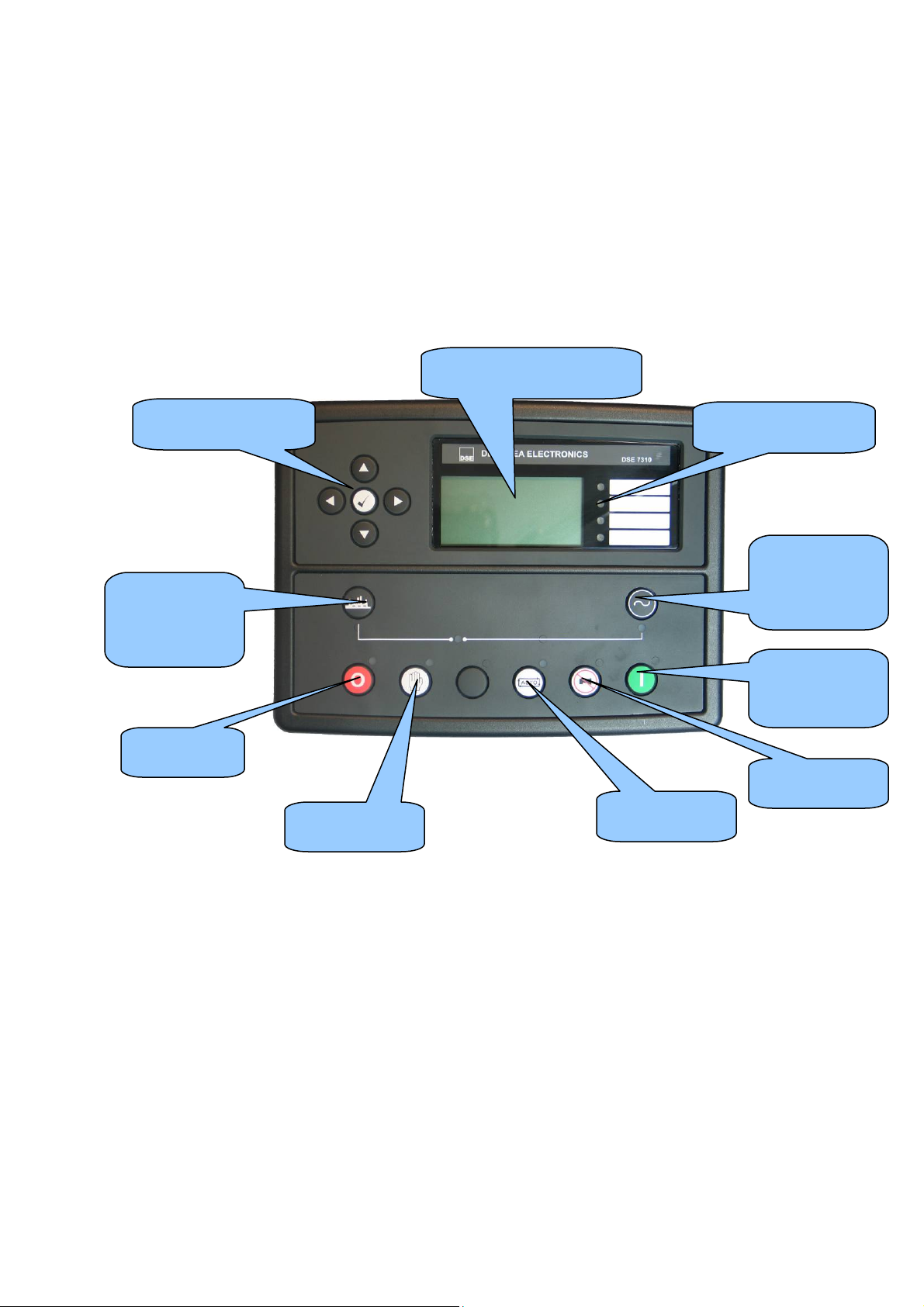
instrumentation display
3 DESCRIPTION OF CONTROLS
The following section details the function and meaning of the various controls on the module.
3.1 DSE7210 / DSE7310 AUTOSTART CONTROL MODULE
Main status and
Menu navigation
Open generator
(manual mode
only)
Select Stop
Select Manual
Four configurable
Close
generator
(manual mode
only)
Start engine
(when in
manual mode)
Mute alarm /
Select Auto
Part No. 057-101 7000 Series Quick Start Guide ISSUE 1 14/04/2009 JR 5
Page 6
DSE Model 7000 Series Quick Start Guide
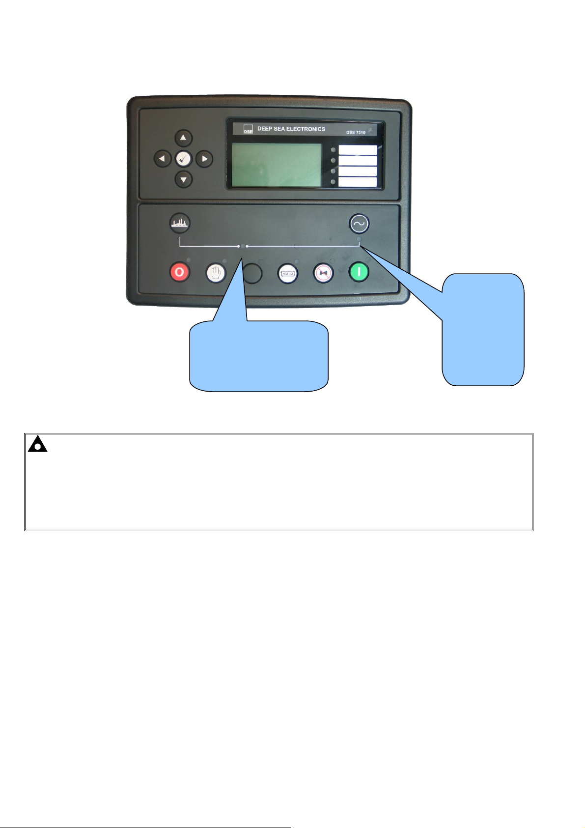
Close Generator LED.
On When The Generator
Is Required To Be On
Load.
Generator
Available
LED.
On when the
generator is
within limits
and able to
take load.
NOTE:- “Generator on load” LED has two modes of operation depending upon the configuration of the
controllers digital inputs.
1) Digital input configured for “Generator closed auxiliary” – The LED illuminates when the generator
closed auxiliary input is active – The LED shows the state of the auxiliary contact.
2) There is NO input configured for “Generator closed auxiliary” (factory default setting) – The LED
illuminates when the 7x20 gives the loading signal to the generator – The LED shows the state of the
7x20’s loading request.
6
Part No. 057-101 7000 Series Quick Start Guide ISSUE 1 14/04/2009 JR
Page 7
DSE Model 7000 Series Quick Start Guide
buttons
mode
mode
mode
Lamp test
instrumentation display
load mode
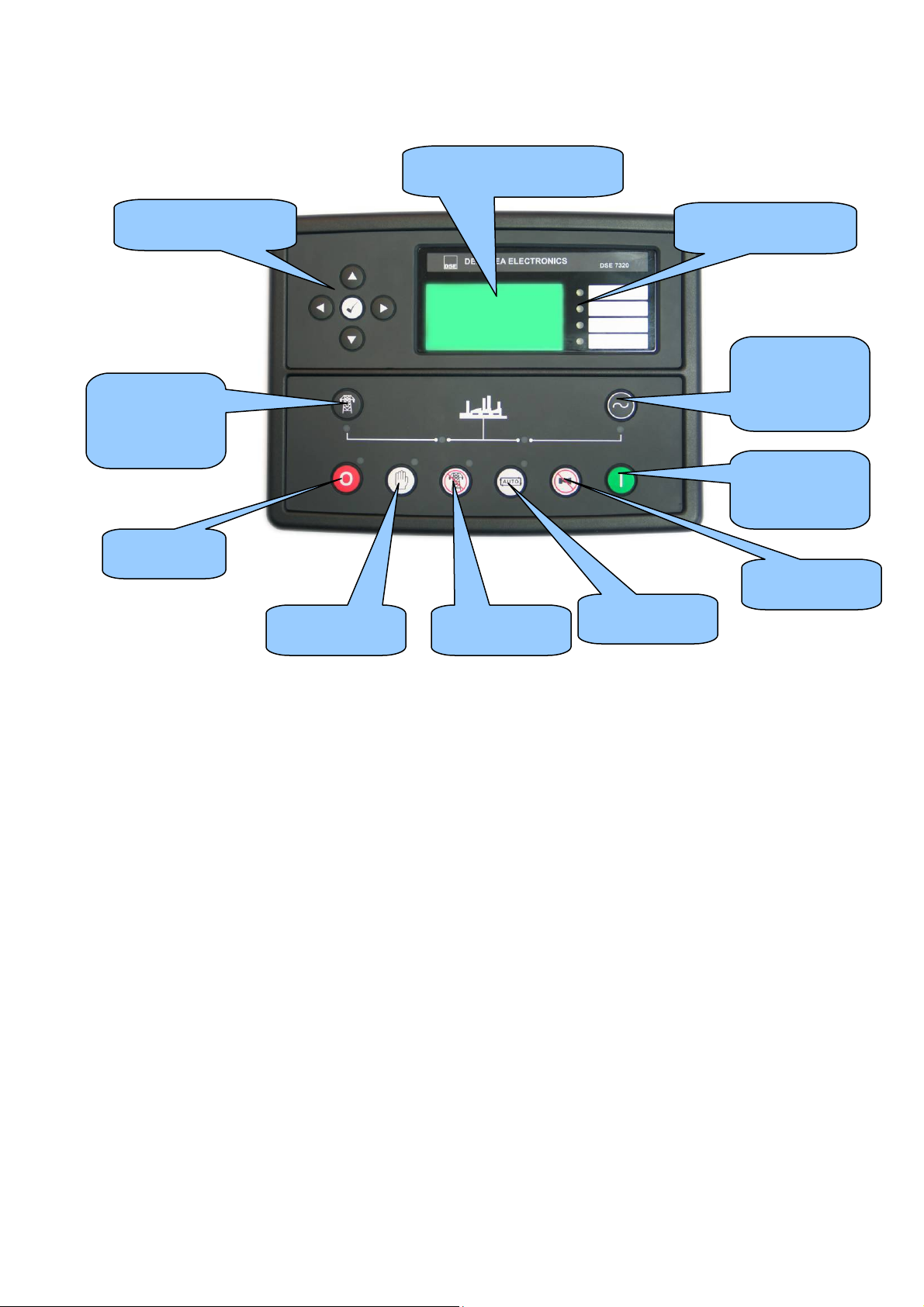
3.2 DSE7220 / DSE7320 AMF CONTROL MODULE
Menu navigation
Transfer to
mains (manual
mode only)
Main status and
Four configurable
LEDs
Transfer to
generator
(manual mode
only)
Start engine
(when in
manual mode)
Select Stop
Continued overleaf….
Select Manual
Select Test on
Mute alarm /
Select Auto
Part No. 057-101 7000 Series Quick Start Guide ISSUE 1 14/04/2009 JR 7
Page 8

Mains Available
LED.
On when the
mains is within
limits and able to
take load.
Close Mains LED.
On When The Generator
Is Required To Be On
Load.
DSE Model 7000 Series Quick Start Guide
Close Generator LED.
On When The Generator
Is Required To Be On
Load.
Generator
Available
LED.
On when the
generator is
within limits
and able to
take load.
NOTE:- “Generator on load” LED has two modes of operation depending upon the configuration of the
controllers digital inputs.
3) Digital input configured for “Generator closed auxiliary” – The LED illuminates when the generator
closed auxiliary input is active – The LED shows the state of the auxiliary contact.
4) There is NO input configured for “Generator closed auxiliary” (factory default setting) – The LED
illuminates when the 7x20 gives the loading signal to the generator – The LED shows the state of the
7x20’s loading request.
NOTE:- “Mains on load” LED has two modes of operation depending upon the configuration of the
controllers digital inputs.
5) Digital input configured for “Mains closed auxiliary” – The LED illuminates when the mains closed
auxiliary input is active – The LED shows the state of the auxiliary contact.
6) There is NO input configured for “Mains closed auxiliary” (factory default setting) – The LED illuminates
when the 7x20 gives the loading signal to the mains – The LED shows the state of the 7x20’s loading
request.
8
Part No. 057-101 7000 Series Quick Start Guide ISSUE 1 14/04/2009 JR
Page 9

DSE Model 7000 Series Quick Start Guide
3.3 QUICKSTART GUIDE
This section provides a quick start guide to the module’s operation.
3.3.1 STARTING THE ENGINE
First, select manual
mode…
…then press the
Start button to crank
the engine.
NOTE:- For further details, see the section entitled ‘OPERATION’ elsewhere in this manual.
3.3.2 STOPPING THE ENGINE
Select Stop/Reset
mode. The generator
is stopped.
NOTE:- For further details, see the section entitled ‘OPERATION’ elsewhere in this manual.
Part No. 057-101 7000 Series Quick Start Guide ISSUE 1 14/04/2009 JR 9
Page 10

DSE Model 7000 Series Quick Start Guide
3.4 VIEWING THE INSTRUMENTS
It is possible to scroll to display the different pages of information by repeatedly operating the next page
button.
Once selected the page will remain on the LCD display until the user selects a different page or after an extended
period of inactivity, the module will revert to the status display.
If no buttons are pressed upon entering an instrumentation page, the instruments will be displayed automatically
subject to the setting of the Scroll Delay.
Alternatively, to scroll manually through all instruments on the currently selected page, press the scroll or
buttons. The ‘autoscroll’ is disabled.
To re-enable ‘autoscroll’ press the or buttons to scroll to the ‘title’ of the instrumentation page (ie
Engine).
When scrolling manually, the display will automatically return to the Status page if no buttons are pressed for the
duration of the configurable LCD Page Timer.
If an alarm becomes active while viewing the status page, the display shows the Alarms page to draw the operator’s
attention to the alarm condition.
Page order:-
Status, Engine, Generator, Mains, Alarms, ECU DTCs (electronic engines only), Event log, Scheduler (if enabled),
About.
First page -
Press to change to the next page -
Status
Engine
If you want to view one of the
instruments towards the end
of the list, it may be quicker to
scroll up through the
Press to change to the next page -
Generator
10
Part No. 057-101 7000 Series Quick Start Guide ISSUE 1 14/04/2009 JR
Page 11

DSE Model 7000 Series Quick Start Guide
3.4.1 INSTRUMENT PAGE CONTENT
Engine
• Engine Speed
• Oil Pressure
• Coolant Temperature
• Engine Battery Volts
• Run Time
• Oil Temperature*
• Coolant Pressure*
• Inlet Temperature*
• Exhaust Temperature*
• Fuel Temperature*
• Turbo Pressure
• Fuel Pressure*
• Fuel Consumption*
• Fuel Used*
• Fuel Level*
• Auxiliary Sensors (If fitted and configured)
• Engine Maintenance Due (If configured)
• Engine ECU Link*
*When connected to suitably configured and compatible engine ECU. For details of supported engines see
‘Electronic Engines and DSE wiring’ (DSE Part number 057-004)
Generator
• Generator Voltage (ph-N)
• Generator Voltage (ph-ph)
• Generator Frequency
• Generator Current
• Generator Earth Current
• Generator Load (kW)
• Generator Load (kVA)
• Generator Power Factor
• Generator Load (kVAr)
• Generator Load (kWh, kVAh, kVArh)
• Generator Phase Sequence
Mains (DSE7220/DSE7320 only)
• Mains Voltage (ph-N)
• Mains Voltage (ph-ph)
• Mains Frequency
About
• Module Type
• Application Version
• USB ID – unique identifier for PC USB connection
• Analogue Measurements Version
• Firmware Update Bootloader Version
Part No. 057-101 7000 Series Quick Start Guide ISSUE 1 14/04/2009 JR 11
Page 12

DSE Model 7000 Series Quick Start Guide
3.4.2 CAN ERROR MESSAGES
When connected to a suitable CAN engine the 7000 series controller displays alarm status messages from the ECU.
Alarm
ECU Warning
Warning
Press to access the list of current active Engine DTCs (Diagnostic Trouble Codes).
Engine DTCs
Water Level
Low
Xxx,xxx,xxx
NOTE:- For details on these code meanings, refer to the ECU instructions provided by the engine
manufacturer, or contact the engine manufacturer for further assistance.
Type of alarm as reported by the ECU
Type of alarm that is triggered in the
DSE module (ie Warning or Shutdown)
The code interpreted by the module shows on the display as a text message.
Additionally, the manufactures code is shown.
NOTE:- For further details on connection to electronic engines please refer to Electronic engines and
DSE wiring. Part No. 057-004
12
Part No. 057-101 7000 Series Quick Start Guide ISSUE 1 14/04/2009 JR
Page 13

DSE Model 7000 Series Quick Start Guide
total of 50 logged events.
3.5 VIEWING THE EVENT LOG
Event log 1/50
Oil Pressure Low
Shutdown
12 Sep 2007, 08:25:46
The 7000 series modules maintains a log of the last 50 shutdown alarms (7200 series
logs 30 shutdown alarms) to enable the operator or engineer to view the past alarms
history.
The event log only includes shutdown and electrical trip alarms logged;
The event log does not contain Warning alarms.
Once the log is full, any subsequent shutdown alarms will overwrite the oldest entry in the log.
Hence, the log will always contain the most recent shutdown alarms.
The module logs the alarm, along with the date and time of the event in the format shown in this example.
Number of present alarms. This is event 1 of a
If All warnings are latched
is configured, the event
log will capture warning
alarms. For more details
consult the 7xxx series
configuration software
To view the event log, repeatedly press the next page button until the LCD screen displays the Event log.
Press down
to view the next most recent shutdown alarm:
Continuing to press down
cycles through the past alarms after which the display shows the most recent
alarm and the cycle begins again.
To exit the event log and return to viewing the instruments, press the next page button.
3.6 USER CONFIGURABLE INDICATORS
These LEDs can be configured by the user to indicate any one of 100+
different functions based around the following:-
• Indications - Monitoring of a digital input and indicating associated
functioning user’s equipment - Such as Battery Charger On or Louver’s
Open, etc.
• WARNINGS and SHUTDOWNS - Specific indication of a particular
warning or shutdown condition, backed up by LCD indication - Such as
Low Oil Pressure Shutdown, Low Coolant level, etc.
• Status Indications - Indication of specific functions or sequences
derived from the modules operating state - Such as Safety On, Pre-
heating, Panel Locked, Generator Available, etc.
User configurable LEDs
Part No. 057-101 7000 Series Quick Start Guide ISSUE 1 14/04/2009 JR 13
Page 14

DSE Model 7000 Series Quick Start Guide
4 OPERATION
The following description details the sequences followed by a module containing the standard ‘factory configuration’.
Remember that if you have purchased a completed generator set or control panel from your supplier, the module’s
configuration will probably have been changed by them to suit their particular requirements.
Always refer to your configuration source for the exact sequences and timers observed by any particular module in
the field.
4.1 ECU OVERRIDE
NOTE:- ECU Override function is only applicable to the CAN variant of the 6100 series controller.
NOTE:- Depending upon system design, the ECU may be powered or unpowered when the module is in
STOP mode. ECU override is only applicable if the ECU is unpowered when in STOP mode.
When the ECU powered down (as is normal when in STOP mode), it is not possible to read the diagnostic trouble
codes or instrumentation. Additionally, it is not possible to use the engine manufacturers’ configuration tools.
As the ECU is usually unpowered when the engine is not running, it must be turned on manually as follows :
• Select STOP mode on the DSE controller.
• Press and hold the START button to power the ECU. As the controller is in STOP mode, the engine will
not be started.
• Continue to hold the start button for as long as you need the ECU to be powered.
• The ECU will remain powered until a few seconds after the START button is released.
This is also useful if the engine manufacturer’s tools need to be connected to the engine, for instance to configure the
engine as the ECU needs to be powered up to perform this operation.
14
Part No. 057-101 7000 Series Quick Start Guide ISSUE 1 14/04/2009 JR
Page 15

DSE Model 7000 Series Quick Start Guide
4.2 AUTOMATIC MODE OF OPERATION
NOTE:- If a digital input configured to panel lock is active, changing module modes will not be
possible. Viewing the instruments and event logs is NOT affected by panel lock.
Activate auto mode be pressing the pushbutton. An LED indicator beside the button confirms this action.
Auto mode will allow the generator to operate fully automatically, starting and stopping as required with no user
intervention.
4.2.1 WAITING IN AUTO MODE
If a starting request is made, the starting sequence will begin.
Starting requests can be from the following sources :
• Mains supply out of limits (DSE7220/7320 only)
• Activation of an auxiliary input that has been configured to remote start
• Activation of the inbuilt exercise scheduler.
4.2.2 STARTING SEQUENCE
To allow for ‘false’ start requests such as mains brownouts, the start delay timer begins.
Should all start requests be removed during the start delay timer, the unit will return to a stand-by state.
If a start request is still present at the end of the start delay timer, the fuel relay is energised and the engine will be
cranked.
NOTE:- If the unit has been configured for CAN, compatible ECU’s will receive the start command via
CAN.
If the engine fails to fire during this cranking attempt then the starter motor is disengaged for the crank rest duration
after which the next start attempt is made. Should this sequence continue beyond the set number of attempts, the
start sequence will be terminated and the display shows Fail to Start.
When the engine fires, the starter motor is disengaged. Speed detection is factory configured to be derived from the
main alternator output frequency but can additionally be measured from a Magnetic Pickup mounted on the flywheel
(Selected by PC using the 7000 series configuration software).
Additionally, rising oil pressure can be used to disconnect the starter motor (but cannot detect underspeed or
overspeed).
NOTE:- If the unit has been configured for CAN, speed sensing is via CAN.
After the starter motor has disengaged, the Safety On timer activates, allowing Oil Pressure, High Engine
Temperature, Under-speed, Charge Fail and any delayed Auxiliary fault inputs to stabilise without triggering the fault.
Part No. 057-101 7000 Series Quick Start Guide ISSUE 1 14/04/2009 JR 15
Page 16

DSE Model 7000 Series Quick Start Guide
4.2.3 ENGINE RUNNING
Once the engine is running, the Warm Up timer, if selected, begins, allowing the engine to stabilise before accepting
the load.
DSE7210/DSE7310 - The generator will be placed on load.
DSE7220/DSE7320 - Load will be transferred from the mains supply to the generator
NOTE:-The load transfer signal remains inactive until the Oil Pressure has risen. This prevents
excessive wear on the engine.
If all start requests are removed, the stopping sequence will begin.
4.2.4 STOPPING SEQUENCE
The return delay timer operates to ensure that the starting request has been permanently removed and isn’t just a
short term removal. Should another start request be made during the cooling down period, the set will return on load.
If there are no starting requests at the end of the return delay timer, the load is transferred back from the generator
to the mains supply and the cooling timer is initiated.
The cooling timer allows the set to run off load and cool sufficiently before being stopped. This is particularly
important where turbo chargers are fitted to the engine.
After the cooling timer has expired, the set is stopped.
16
Part No. 057-101 7000 Series Quick Start Guide ISSUE 1 14/04/2009 JR
Page 17

DSE Model 7000 Series Quick Start Guide
4.3 MANUAL OPERATION
NOTE:- If a digital input configured to panel lock is active, changing module modes will not be
possible. Viewing the instruments and event logs is NOT affected by panel lock.
Activate Manual mode be pressing the pushbutton. An LED indicator beside the button confirms this action.
Manual mode allows the operator to start and stop the set manually, and if required change the state of the load
switching devices.
4.3.1 WAITING IN MANUAL MODE
When in manual mode, the set will not start automatically.
To begin the starting sequence, press the
button.
4.3.2 STARTING SEQUENCE
NOTE:- There is no start delay in this mode of operation.
The fuel relay is energised and the engine is cranked.
NOTE:- If the unit has been configured for CAN, compatible ECU’s will receive the start command via
CAN.
If the engine fails to fire during this cranking attempt then the starter motor is disengaged for the crank rest duration
after which the next start attempt is made. Should this sequence continue beyond the set number of attempts, the
start sequence will be terminated and the display shows Fail to Start.
When the engine fires, the starter motor is disengaged. Speed detection is factory configured to be derived from the
main alternator output frequency but can additionally be measured from a Magnetic Pickup mounted on the flywheel
(Selected by PC using the 7000 series configuration software).
Additionally, rising oil pressure can be used disconnect the starter motor (but cannot detect underspeed or
overspeed).
NOTE:- If the unit has been configured for CAN, speed sensing is via CAN.
After the starter motor has disengaged, the Safety On timer activates, allowing Oil Pressure, High Engine
Temperature, Under-speed, Charge Fail and any delayed Auxiliary fault inputs to stabilise without triggering the fault.
Part No. 057-101 7000 Series Quick Start Guide ISSUE 1 14/04/2009 JR 17
Page 18

DSE Model 7000 Series Quick Start Guide
4.3.3 ENGINE RUNNING
In manual mode, the load is not transferred to the generator unless a ‘loading request’ is made.
A loading request can come from a number of sources.
• Pressing the transfer to generator button
• Mains supply out of limits (DSE7220/DSE7320 only)
• Activation of an auxiliary input that has been configured to remote start on load
• Activation of the inbuilt exercise scheduler if configured for ‘on load’ runs.
NOTE:-The load transfer signal remains inactive until the Oil Pressure has risen. This prevents
excessive wear on the engine.
Once the load has been transferred to the generator, it will not be automatically transferred back to the mains
supply. To manually transfer the load back to the mains either:
• Press the transfer to mains button (DSE7220/DSE7320 only)
• Press the Open Generator button (DSE7210/DSE7310 only)
• Press the auto mode button to return to automatic mode.
4.3.4 STOPPING SEQUENCE
In manual mode the set will continue to run until either :
• The stop button
• The auto button is pressed. The set will observe all auto mode start requests and stopping timers
before beginning the Auto mode stopping sequence.
is pressed – The set will immediately stop
18
Part No. 057-101 7000 Series Quick Start Guide ISSUE 1 14/04/2009 JR
Page 19

DSE Model 7000 Series Quick Start Guide
4.4 TEST MODE OF OPERATION
NOTE:- Test Mode is only applicable to DSE7220/DSE7320 controllers.
NOTE:- If a digital input configured to panel lock is active, changing module modes will not be
possible. Viewing the instruments and event logs is NOT affected by panel lock.
Activate test mode be pressing the pushbutton. An LED indicator beside the button confirms this action.
Test mode will start the set and transfer the load to the generator to provide a Test on load function.
4.4.1 WAITING IN TEST MODE
When in test mode, the set will not start automatically.
To begin the starting sequence, press the
button.
4.4.2 STARTING SEQUENCE
The set begins to crank.
NOTE:- If the unit has been configured for CAN, compatible ECU’s will receive the start command via
CAN.
If the engine fails to fire during this cranking attempt then the starter motor is disengaged for the crank rest duration
after which the next start attempt is made. Should this sequence continue beyond the set number of attempts, the
start sequence will be terminated and the display shows Fail to Start.
When the engine fires, the starter motor is disengaged. Speed detection is factory configured to be derived from the
main alternator output frequency but can additionally be measured from a Magnetic Pickup mounted on the flywheel
(Selected by PC using the 7000 series configuration software).
Additionally, rising oil pressure can be used disconnect the starter motor (but cannot detect underspeed or
overspeed).
NOTE:- If the unit has been configured for CAN, speed sensing is via CAN.
After the starter motor has disengaged, the Safety On timer activates, allowing Oil Pressure, High Engine
Temperature, Under-speed, Charge Fail and any delayed Auxiliary fault inputs to stabilise without triggering the fault.
Part No. 057-101 7000 Series Quick Start Guide ISSUE 1 14/04/2009 JR 19
Page 20

DSE Model 7000 Series Quick Start Guide
4.4.3 ENGINE RUNNING
Once the engine is running, the Warm Up timer, if selected, begins, allowing the engine to stabilise before accepting
the load.
Load will be automatically transferred from the mains supply to the generator.
NOTE:-The load transfer signal remains inactive until the Oil Pressure has risen. This prevents
excessive wear on the engine.
In test mode, the set will continue to run on load until either:
• The stop button is pressed – The set will immediately stop
• The auto button is pressed. The set will observe all auto mode start requests and stopping timers
before beginning the Auto mode stopping sequence.
20
Part No. 057-101 7000 Series Quick Start Guide ISSUE 1 14/04/2009 JR
Page 21

DSE Model 7000 Series Quick Start Guide
Part No. 057-101 7000 Series Quick Start Guide ISSUE 1 14/04/2009 JR 21
 Loading...