

Page 1

1
Deep Sea Electronics Plc
P130 input expansion module /
549 remote annunciator
Operators manual
Author – Tony Manton
Deep Sea Electronics Plc
Highfield House
Hunmanby Industrial Estate
North Yorkshire
YO14 0PH
ENGLAND
Tel +44 (0) 1723 890099
Fax +44 (0) 1723 893303
Email : sales@deepseaplc.com
P130 operators manual ISSUE 2 14/6/04 AM
Page 2

<<< THIS PAGE INTENTIONALLY BLANK >>>
P130 operators manual ISSUE 2 14/6/04 AM
2
Page 3

3
TABLE OF CONTENTS
Section Page
1 INTRODUCTION .............................................................................................. 4
2 CLARIFICATION OF NOTATION USED WITHIN THIS PUBLICATION. ........4
3 P130 INPUT EXPANSION MODULE ............................................................... 5
3.1 DESCRIPTION OF OPERATION.....................................................................................5
3.1.1 TYPICAL CONNECTION SCHEMATIC :...................................................................5
3.2 INPUT CONFIGURATION ...............................................................................................6
3.3 PANEL LAYOUT .............................................................................................................6
3.4 TERMINAL DESCRIPTION .............................................................................................7
3.4.1 CONNECTOR 1........................................................................................................7
3.4.2 CONNECTOR 2........................................................................................................7
3.5 130 INPUT EXPANSION SPECIFICATION .....................................................................8
3.6 TYPICAL WIRING DIAGRAM..........................................................................................8
4 549 REMOTE ANNUNCIATOR ........................................................................9
4.1 DESCRIPTION OF OPERATION.....................................................................................9
4.1.1 FRONT PANEL LAYOUT..........................................................................................9
4.1.2 REAR PANEL LAYOUT..........................................................................................10
4.2 TERMINAL DESCRIPTION ........................................................................................... 10
4.2.1 CONNECTOR 1......................................................................................................10
4.2.2 TYPICAL CONNECTION SCHEMATICS : ..............................................................11
4.3 549 REMOTE ANNUNCIATOR SPECIFICATION..........................................................11
4.4 TYPICAL WIRING DIAGRAM........................................................................................ 11
5 TYPICAL WIRING DIAGRAM OF P130 WITH P549 ..................................... 12
P130 operators manual ISSUE 2 14/6/04 AM
Page 4
1 INTRODUCTION
The P130 is used to expand the input capability of the 53xx series of DSE controllers. It provides
the controllers with 8 additional digital inputs and 2 additional analogue inputs.
Also provided is support for the DSE Model 549 remote annunciator, used to help system
manufacturers meet the requirements of the NFPA110 level 1 specifications (USA).
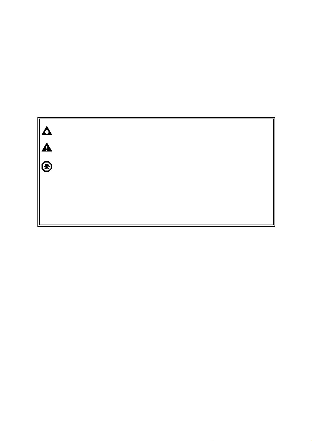
2 CLARIFICATION OF NOTATION USED WITHIN THIS
PUBLICATION.
NOTE:
CAUTION!:
WARNING!:
NFPA110 National Fire Protection Authority (USA). NFPA110 covers emegency power
Highlights an essential element of a procedure to ensure correctness.
Indicates a procedure or practice which, if not strictly observed, could
result in damage or destruction of equipment.
Indicates a procedure or practice which could result in injury to personnel
or loss of life if not followed correctly.
Deep Sea Electronics Plc owns the copyright to this manual, which cannot
be copied, reproduced or disclosed to a third party without prior written
permission.
systems (EPS) including generating systems. NFPA110 Level 2 is met by
most DSE controllers. NFPA Level 1 requires additional remote indication of
some control and alarm conditions.
P130 operators manual ISSUE 2 14/6/04 AM
4
Page 5

5
3 P130 INPUT EXPANSION MODULE
Configuration / monitoring PC
548
annunciator
3.1 DESCRIPTION OF OPERATION
The P130 connects to the expansion port of the 53xx series controllers. This port is also used for
157 relay expansion and 545/548 LED expansion.
Each DSE 53xx series controller can support one P130 input expansion and up to two output
expansions.
Where both input and output expansions are used with the same 53xx controller, the modules are
connected in ‘daisy chain’ fashion. It does not matter which expansion is ‘first’ in the chain.
Additionally, the P130 has support for the DSE 549 Remote Annunciator. For details on this, refer
to the section headed 549 Remote Annunciator elsewhere in this manual.
When DC power is applied to the P130, the ‘power on’ LED will illuminate.
The 130 sends data containing the states of the analogue and digital inputs to the host controller.
The host controller then decides what action (if any) is to be taken, depending upon the module’s
configuration and the states of the expansion inputs.
3.1.1 TYPICAL CONNECTION SCHEMATIC :
549 Remote Annunciator
P810 interface
and cable
Expansion
cable
OR
Expansion cable
5300 series
Expansion cable
130 Input Expansion
NOTE:- Previously, the 53xx expansion port was used solely for output expansion.
For this reason, modules manufactured prior to the release of the P130 input
expansion module may be marked as : 157/548
These ‘early’ modules are NOT compatible with the P130 input expansion module.
NOTE:-When using 549 annunciator, 157 relay boards or 548 annunciators may
still be connected to give voltsfree (dry) contacts or secondary indication of the items
annunciated by the 549. Ie Only 16 unique expansion outputs/Leds can be configured.
To further
expansion
(157/548)
P130 operators manual ISSUE 2 14/6/04 AM
Page 6

3.2 INPUT CONFIGURATION
controller
expansion
Power on LED
Cable fault LED
Configuration of the expansion inputs is performed by configuring the master controller module.
This instructs the controller how to interface with the expansion modules. The input expansion
module is not directly configurable.
For further details on module configuration, you are referred to the relevant configuration software
manual.
3.3 PANEL LAYOUT
Connector 1
Connector 2
To ‘host’
Further
P130 operators manual ISSUE 2 14/6/04 AM
6
Page 7

7
3.4 TERMINAL DESCRIPTION
3.4.1 CONNECTOR 1
PIN No DESCRIPTION CABLE SIZE NOTES
1 Plant supply negative 1.0mm
2 Plant supply positive 1.0mm
3 Digital input expansion 1 0.5mm
4 Digital input expansion 2 0.5mm
5 Digital input expansion 3 0.5mm
6 Digital input expansion 4 0.5mm
7 Digital input expansion 5 0.5mm
8 Digital input expansion 6 0.5mm
9 Digital input expansion 7 0.5mm
10 Digital input expansion 8 0.5mm
11 Analogue input expansion 1 0.5mm
12
Analogue input expansion 1
return
0.5mm
13 Analogue input expansion 2 0.5mm
14
Analogue input expansion 2
return
0.5mm
2
2
2
Recommended fuse 2A anti-surge
Requires a contact to plant supply
negative.
2
Requires a contact to plant supply
negative.
2
Requires a contact to plant supply
negative.
2
Requires a contact to plant supply
negative.
2
Requires a contact to plant supply
negative.
2
Requires a contact to plant supply
negative.
2
Requires a contact to plant supply
negative.
2
Requires a contact to plant supply
negative.
2
Connect to plant supply negative if
unused
2
Connect to plant supply negative if
unused
2
Connect to plant supply negative if
unused
2
Connect to plant supply negative if
unused
3.4.2 CONNECTOR 2
PIN No DESCRIPTION CABLE SIZE NOTES
A 0V 0.5mm
B A 0.5mm
C B 0.5mm
D +12V 0.5mm
CAUTION!: Connector 2 is only intended for connection to the DSE 549 annunciator.
Connection to any other device may cause damage and will invalidate the warranty.
2
2
2
2
Thinner cable will reduce the maximum
allowable cable length
P130 operators manual ISSUE 2 14/6/04 AM
Page 8

3.5 130 INPUT EXPANSION SPECIFICATION
DC Supply
Cranking Dropouts
Max. Operating Current
Dimensions
Operating Temperature Range
IP Rating of P130
Connector 2 max cable length to
549 remote annunciator
8.0 to 35 V Continuous.
Able to survive 0 V for 50 mS, providing supply was at least
10 V before dropout and supply recovers to 5V
150mA at 12V. 81mA at 24V. This maximum current
includes connection of the P549 remote annunciator, which
is powered by the P130.
171mm x 115mm x 49mm ( 6¾” x 4½” x 2” )
-30°C to +70°C
IP20
1000m with cable of 0.5mm2cross section
500m with cable of 0.2mm2cross section (typical 4 core
3.6 TYPICAL WIRING DIAGRAM
burglar alarm/telephone wire)
P130 operators manual ISSUE 2 14/6/04 AM
8
Page 9

9
4 549 REMOTE ANNUNCIATOR
4.1 DESCRIPTION OF OPERATION
The model 549 remote annunciator is intended to help system manufacturers meet the
requirements of the NFPA110 level 1 specification by providing indication of the required
control/alarm status. A ‘spare’ channel is provided that be configured to one of a number of choices
to help the system manufacturer meet more complex specifications.
The 549 is connected via a 4 core cable to the connector 2 socket of the DSE P130 input
expansion module.
For connection details, see the sections headed Terminal Description and Typical Wiring Diagram
elsewhere in this manual.
Correct connection of the 4 core cable to a correctly connected and operating P130 input
expansion module will illuminate the Power LED.
If the P130 input expansion module does not have DC power connected to it, or the 4 core cable is
not correctly terminated, the 549’s Power LED will remain extinguished.
Failure of the data signal to the 549 from the P130 (terminals B & C) will cause the Link Lost LED
to flash.
The 549 features an internal sounder that is activated upon detection of any of the channels (with
the exception of ‘EPS supplying load’).
The sounder can be muted by pressing the integral alarm mute button. Once muted, any
subsequent alarm condition will retrigger the sounder.
Pressing the lamp test button will illuminate all LEDs to prove their operational state.
4.1.1 FRONT PANEL LAYOUT
Panel cutout : 154mm x 98mm ( 6.1” x 3.9” )
P130 operators manual ISSUE 2 14/6/04 AM
Page 10

4.1.2 REAR PANEL LAYOUT
Connector 1
4.2 TERMINAL DESCRIPTION
4.2.1 CONNECTOR 1
PIN No DESCRIPTION CABLE SIZE NOTES
A 0V 0.5mm
B A 0.5mm
C B 0.5mm
D +12V 0.5mm
2
2
2
2
Thinner cable will reduce the maximum
allowable cable length
CAUTION!: Connector 1 is only intended for connection to the DSE 549 annunciator.
Connection to any other device may cause damage and will invalidate the warranty.
P130 operators manual ISSUE 2 14/6/04 AM
10
Page 11

11
4.2.2 TYPICAL CONNECTION SCHEMATICS :
Configuration / monitoring PC
P810 interface
and cable
549 Remote Annunciator
548 annunciator
Expansion
cable
OR
Expansion cable
5300 series
Expansion cable
130 Input Expansion
NOTE:- Previously, the 53xx expansion port was used solely for output expansion.
For this reason, modules manufactured prior to the release of the P130 input
expansion module may be marked as : 157/548
These ‘early’ modules are not compatible with the P130 input expansion module.
4.3 549 REMOTE ANNUNCIATOR SPECIFICATION
To further
expansion
(157/548)
DC Supply
Cranking Dropouts
8.0 to 35 V Continuous.
Able to survive 0 V for 50 mS, providing supply was at least
10 V before dropout and supply recovers to 5V
Max. Operating Current
Dimensions
Operating Temperature Range
IP Rating of P549 fascia
Connector 1 max cable length to
P130 input expansion module
150mA at 12V. 81mA at 24V. This maximum current includes the
P130, which provides power to the P549.
171mm x 115mm x 49mm ( 6¾” x 4½” x 2” )
-30°C to +70°C
IP55 when fitted into control panel with supplied gasket
1000m with cable of 0.5mm2cross section
500m with cable of 0.2mm2cross section (typical 4 core
4.4 TYPICAL WIRING DIAGRAM
burglar alarm/telephone wire)
P130 operators manual ISSUE 2 14/6/04 AM
Page 12

5 TYPICAL WIRING DIAGRAM OF P130 WITH P549
P130 operators manual ISSUE 2 14/6/04 AM
12
 Loading...