

Page 1
INSTALLATION INSTRUCTIONS
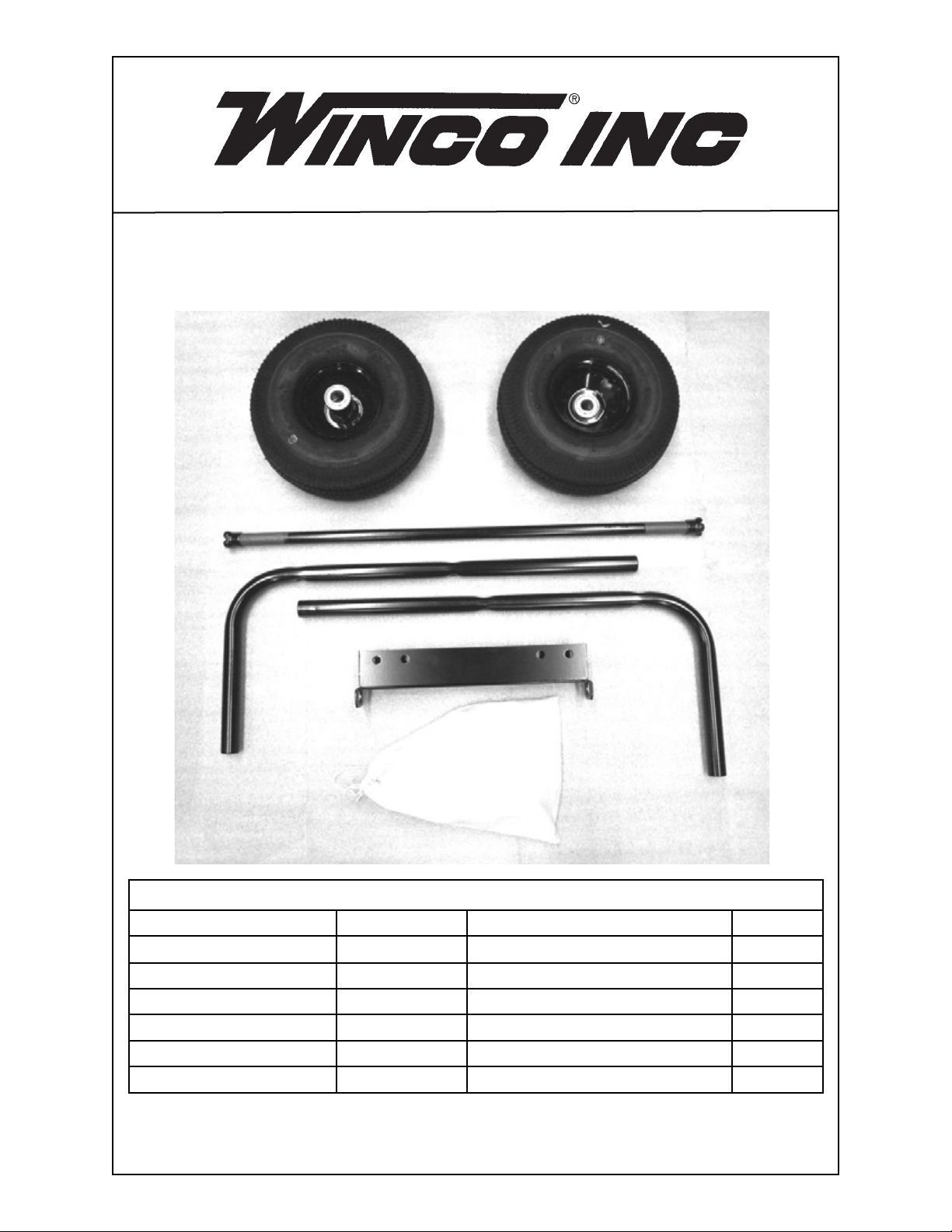
2 WHEEL DOLLY KIT
1
2
3
4
6
5
COMPONENT LIST
REF. # PART # DESCRIPTION QTY.
1 SEE NOTE BELOW
2 64326-019 Axle 1
3 16205-007 Leg Support & Handle 2
4 15775-002 Axle Bracket 1
5 16204-101 Bag of Parts 1
6 16343-000 Axle Shaft Protector 2
NOTE: Pneumatic Wheel & Tire shown.
Pneumatic Wheel & Tire is part # 43657-003 (optional replacement)
43657-008 Hard Rubber Wheel & Tire 2
113038-02 16204-007I
Page 2
STEP 1
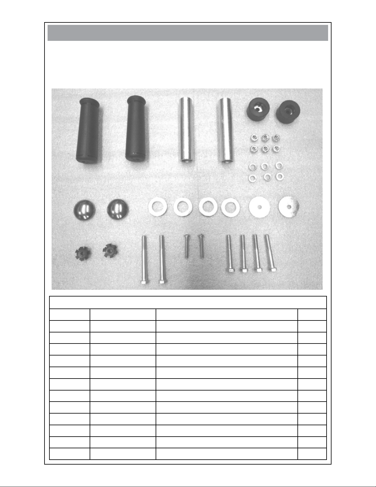
Open hardware bag and account for all hardware and fasteners.
•
FASTENERS & MISC. COMPONENTS
(not shown in actual size)
9
7
13
12
16
15
HARDWARE & FASTENER LIST
8
10
11
14
18
17
REF. # PART # DESCRIPTION QTY.
7 64325-001 Rubber Grip 2
8 64688-005 Axle Stub 2
9 20191-000 Bumper 2
10
11 480-000 5/16” Lock Washer 6
12
13 1178-000 1 3/8” Flat Washer
14
15 15967-000
16 91107-000 5/16”-18 X 3 1/2” Bolt
17
18 471-000 5/16” X 2 1/4” Bolt
458-000 5/16” - 18 Hex Nut 6
64327-000 Hub Cap 2
4
2586-002 1 1/2” Flat Washer 2
Tube Clamp 2
2
639-000 1/4” - 20 X 1 1/2” Bolt 2
4
213038-02 16204-007I
Page 3

STEP 2
Remove the generator from the pallet and block generator up 8 to 10 inches to
•
gain access to the bottom of the cradle assembly. A lifting jack or hoist may also
be used if available.
STEP 3
Thread bolt (ref. 17) onto tube clamp (ref. 15) convex side up as shown.
•
•
With a hammer gently tap tube clamp (ref. 15) into leg support and handle (ref. 3)
approximately 1/2 inch. Remove bolt (ref. 17).
•
Assembly bolt (ref. 17), bumper (ref. 9) and washer (ref. 14) according to the pic
ture below. Tighten assembly onto leg support and handle (ref. 3).
Soak rubber grip (ref. 7) in soapy water prior to installation. Place rubber grip on
•
leg support and handle using a twisting motion.
Repeat for other leg support and handle assembly.
•
-
313038-02 16204-007I
Page 4

STEP 4
Attach leg support and handle assembly to the cradle using bolts (ref. 18), lock
•
washers (ref. 11) and nuts (ref. 10). Repeat for other leg support and handle as
sembly.
Engine End
-
STEP 5
Place axle bracket (ref. 4) under the cradle (engine end) and attach using bolts
•
(ref. 16), nuts (ref. 10) and lock washers (ref. 11). It is centered on the cradle.
Remove and discard axle protectors (ref. 6). Place spacer (ref. 8), washer (ref.
•
13), wheel (ref. 1), washer (ref. 13) on the axle. Then tab the hubcap (ref. 12) on
the axle. Then slide assembly through axle bracket. (ref. 4) Place other spacer,
washer, wheel, washer and hubcap on axle.
•
Remove the blocks under the gen-set. Tap the other hubcap (ref. 12) onto the
axle. NOTE: Do not tap too hard as you may dent the hubcaps.
Winco Inc.
Service Dept.
507-357-6831
413038-02 16204-007I
 Loading...