

Page 1
INSTRUCTION MANUAL
FOR
DIGITAL GENSET CONTROLLER
DGC-2020
****
Publication: 9400200990
Revision: B 11/06
Page 2

Page 3

INTRODUCTION
This instruction manual provides information about the operation and installation of the DGC-2020 Digital
Genset Controller. To accomplish this, the following information is provided:
• General Information and Specifications
• Controls and Indicators
• Functional Description
• Graphical User Interface Operation
• Installation
• Maintenance and Troubleshooting
• Appendices containing Time Overcurrent Characteristic Curves and Modbu s™ Communication
WARNING!
To avoid personal injury or equipment damage, only qualified personnel should
perform the procedures in this manual.
NOTE
Be sure that the controller is hard-wired to earth ground with no smaller than 12
AWG copper wire attached to the chassis ground terminal on the rear of the unit.
When the controller is configured in a system with other devices, it is
recommended to use a separate lead to the ground bus from each unit.
9400200990 Rev B DGC-2020 Introduction i
Page 4

First Printing: September 2006
Printed in USA
© 2006 Basler Electric, Highland Illinois 62249 USA
All Rights Reserved
November 2006
CONFIDENTIAL INFORMATION
of Basler Electric, Highland Illinois, USA. It is loaned for confidential use, subject
to return on request, and with the mutual understanding that it will not be used in
any manner detrimental to the interest of Basler Electric.
It is not the intention of this manual to cover all details and variations in equipment, nor does this manual
provide data for every possible contingency regarding installation or operation. The availability and design
of all features and options are subject to modification without notice. Should further information be
required, contact Basler Electric.
BASLER ELECTRIC
ROUTE 143, BOX 269
HIGHLAND IL 62249 USA
http://www.basler.com, info@basler.com
PHONE +1 618.654.2341 FAX +1 618.654.2351
ii DGC-2020 Introduction 9400200990 Rev B
Page 5

PRODUCT REVISION HISTORY
The following information provides a historical summary of the changes made to the embedded software
(firmware), PC software (BESTCOMSPlus), and hardware of the DGC-2020. The corresponding revisions
made to this instruction manual (9400200990) are also summarized. Revisions are listed in chronological
order.
Firmware Version Change
1.00.04, 11/06
BESTCOMSPlus Version Change
1.00.07, 11/06
Hardware Version Change
—, 10/06
Manual Revision Change
B, 11/06
• Initial release
• Initial release
• Initial release
• Initial release
9400200990 Rev B DGC-2020 Introduction iii
Page 6

This page intentionally left blank.
iv DGC-2020 Introduction 9400200990 Rev B
Page 7

CONTENTS
SECTION 1 • GENERAL INFORMATION ................................................................................................ 1-1
SECTION 2 • HUMAN-MACHINE INTERFACE....................................................................................... 2-1
SECTION 3 • FUNCTIONAL DESCRIPTION...........................................................................................3-1
SECTION 4 • BESTCOMSPlus SOFTWARE...........................................................................................4-1
SECTION 5 • BESTlogic+ PROGRAMMABLE LOGIC............................................................................. 5-1
SECTION 6 • INSTALLATION .................................................................................................................. 6-1
SECTION 7 • MAINTENANCE AND TROUBLESHOOTING.................................................................... 7-1
APPENDIX A • TIME OVERCURRENT CHARACTERISTIC CURVES...................................................A-1
APPENDIX B • MODBUS™ COMMUNICATION......................................................................................B-1
9400200990 Rev B DGC-2020 Introduction v
Page 8

This page intentionally left blank.
vi DGC-2020 Introduction 9400200990 Rev B
Page 9

SECTION 1 • GENERAL INFORMATION
TABLE OF CONTENTS
SECTION 1 • GENERAL INFORMATION ................................................................................................ 1-1
DESCRIPTION....................................................................................................................................... 1-1
FEATURES............................................................................................................................................ 1-1
FUNCTIONS .......................................................................................................................................... 1-1
Generator Protection and Metering.................................................................................................... 1-1
Engine Protection and Metering......................................................................................................... 1-1
Event Recording................................................................................................................................. 1-1
Auto-Synchronizer.............................................................................................................................. 1-1
Contact Inputs and Output Contacts .................................................................................................. 1-1
Automatic Transfer Switch Control (Mains Failure)............................................................................ 1-2
Communication................................................................................................................................... 1-2
STYLE NUMBER ................................................................................................................................... 1-2
SPECIFICATIONS ................................................................................................................................. 1-3
Operating Power ................................................................................................................................ 1-3
Power Consumption ........................................................................................................................... 1-3
Battery Ride Through ......................................................................................................................... 1-3
Current Sensing ................................................................................................................................. 1-3
Voltage Sensing ................................................................................................................................. 1-4
Contact Sensing ................................................................................................................................. 1-4
Engine System Inputs ........................................................................................................................ 1-4
Output Contacts ................................................................................................................................. 1-5
Metering.............................................................................................................................................. 1-5
Generator Protection Functions ......................................................................................................... 1-7
Logic Timers....................................................................................................................................... 1-7
Communication Interface ................................................................................................................... 1-8
Real-Time Clock................................................................................................................................. 1-8
Type Tests.......................................................................................................................................... 1-9
Environment ....................................................................................................................................... 1-9
Agency Approvals .............................................................................................................................. 1-9
CE Compliance ................................................................................................................................ 1-10
Physical ............................................................................................................................................ 1-10
Figures
Figure 1-1. DGC-2020 Style Chart ............................................................................................................ 1-3
9400200990 Rev B DGC-2020 General Information i
Page 10

This page intentionally left blank.
ii DGC-2020 General Information 9400200990 Rev B
Page 11

SECTION 1 • GENERAL INFORMATION
DESCRIPTION
The DGC-2020 Digital Genset Controller provides integrated engine-genset control, protection, and
metering in a single package. Microprocessor based technology allows for exact measurement, setpoint
adjustment, and timing functions. Front panel controls and indicators enable quick and simple DGC-2020
operation. Basler Electric communication software (BESTCOMSPlus) allows units to be easily customized
for each application. Because of the low sensing burden in the DGC-2020, dedicated potential
transformers (PTs) are not required. A wide temperature-range liquid crystal display (LCD) with
backlighting can be viewed under a wide range of ambient light and temperature conditions.
FEATURES
DGC-2020 Digital Genset Controllers have the following features:
• Local and Remote Generator Control
• Engine and Generator Protection
• Programmable Analog Engine Senders
• ECU Communications via SAE J1939
• 16 Programmable Contact Inputs
• Programmable Logic
• Automatic Transfer Switch Control (Mains Failure)
• Integrated RS485
• Auto Synchronizing
FUNCTIONS
DGC-2020 Digital Genset Controllers perform the following functions:
Generator Protection and Metering
Multifunction generator protection guards against generator overvoltage, undervoltage, underfrequency,
and overfrequency. Overcurrent and phase imbalance protection is available as an option. Each
generator protection function has an adjustable pickup and time delay setting. Sixteen inverse time
curves enable the DGC-2020 to offer overcurrent protection in a variety of applications.
Metered generator parameters include voltage, current, real power (watts), apparent power (VA), and
power factor (PF).
Engine Protection and Metering
Engine protection features include oil pressure and coolant temperature monitoring, overcrank protection,
ECU specific protection elements, and diagnostic reporting.
Metered engine parameters include, oil pressure, coolant temperature, battery voltage, speed, fuel level,
engine load, coolant level (from ECU), ECU specific parameters, and run-time statistics.
Event Recording
An event log retains a history of system events in nonvolatile memory. Up to 30 event types are retained
and each record contains a time stamp of the first and last occurrence, and the number of occurrences for
each event.
Auto-Synchronizer
An optional automatic synchronizer monitors the bus and generator voltages and supplies discrete
raise/lower correction signals to synchronize the generator voltage, frequency, and slip angle with that of
the bus.
Contact Inputs and Output Contacts
DGC-2020 controllers have one, dedicated emergency stop contact input and 16 programmable contact
inputs. All contact inputs recognize dry contacts. The programmable inputs can be configured to initiate a
9400200990 Rev B DGC-2020 General Information 1-1
Page 12

pre-alarm or alarm. A programmable input can be programmed to receive an input from an automatic
transfer switch or override DGC-2020 alarms and protection functions. Each programmable input can be
assigned a user-defined name for easy identification at the front panel display and in fault records.
Output contacts include three dedicated relays for energizing an engine’s glow plugs, fuel solenoid, and
starter solenoid. An additional four user-programmable output contacts are provided if the style number is
xxAxxxxxx. If the style number is xxBxxxxxx, an additional twelve output contacts are provided.
Additional contact inputs and output contacts can be accommodated with separate I/O modules. Contact
Basler Electric for availability and ordering information.
Automatic Transfer Switch Control (Mains Failure)
The DGC-2020 has the ability to detect a mains failure via a single-phase Bus input. A mains failure is
established when any one of the following conditions are met:
• Bus voltage falls below dead bus threshold
• Bus voltage unstable due to overvoltage or undervoltage
• Bus voltage unstable due to overfrequency or underfrequency
At this time, the DGC-2020 will start the genset and when ready, apply power to the load via the genset.
When the mains returns and is considered stable, the DGC-2020 will transfer the load back to the mains.
Communication
Standard DGC-2020 communication features include a standard USB port and SAE J1939 interface.
Optional communication features include a dial-out modem and RS-485 communication port.
USB Port
A USB communication port can be used with BESTCOMSPlus software to quickly configure a DGC-2020
with the desired settings or retrieve metering values and event log records.
CANBus Interface
A CANBus interface provides high-speed communication between the DGC-2020 and the engine control
unit (ECU) on an electronically controlled engine. This interface provides access to oil pressure, coolant
temperature, and engine speed data by reading these parameters directly from the ECU. When available,
engine diagnostic data can also be accessed. The CANBus interface supports the following protocols:
• SAE J1939 Protocol - Oil pressure, coolant temperature, and engine speed data are received from
the ECU. In addition, DTCs (Diagnostic Trouble Codes) help diagnose any engine or related failures.
The engine DTCs are displayed on the front panel of the DGC-2020 and may be obtained using
BESTCOMSPlus software.
MTU/MDEC Protocol - A DGC-2020 connected to a genset equipped with an MTU MDEC receives
•
Oil pressure, coolant temperature, and engine speed data from the engine controller, along with
various alarms and pre-alarms that are MDEC specific. In addition, the DGC-2020 tracks and displays
the active fault codes issued by the MDEC ECU.
Dial-Out Modem
One of two optional, dial-out modems (a US version or international version) enables remote control,
monitoring, and setting of the DGC-2020. When an alarm or pre-alarm condition occurs, the DGC-2020
can dial up to four telephone numbers, in sequence, until an answer is received and the condition is
annunciated.
RS-485 Port
An optional RS-485 communication port uses the Modbus communication protocol and enables remote
control and monitoring of the DGC-2020 over a polled network.
STYLE NUMBER
Standard-order DGC-2020 controllers are identified by a style number which consists of a combination of
letters and numbers that define the controller’s electrical characteristics and operational features. The
model number, together with the style number, describe the options included in a specific controller.
Figure 1-1 illustrates the DGC-2020 style number identification chart.
1-2 DGC-2020 General Information 9400200990 Rev B
Page 13
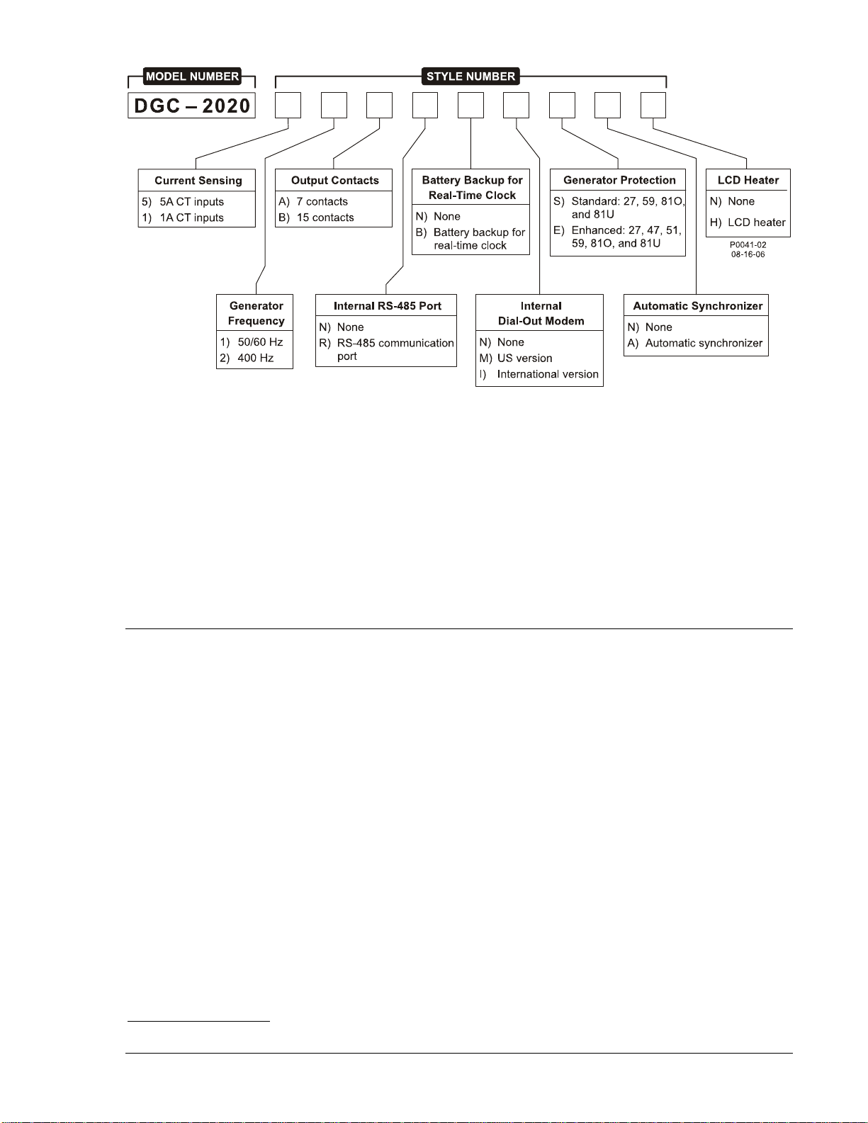
Figure 1-1. DGC-2020 Style Chart
For example, if a DGC-2020 style number is 51BNBMEAH, the controller would have the following
characteristics and operating features.
5 5 Aac current sensing inputs
1 50/60 hertz nominal generator frequency
B 3 fixed-function output contacts and 12 programmable output contacts
N No RS-485 communication port
B Battery backup for real-time clock during losses of control power
M Internal dial-out modem—US version
E Enhanced generator protection (undervoltage, phase imbalance, overcurrent, overvoltage,
overfrequency, and underfrequency)
A Auto-synchronizer
H LCD heater
SPECIFICATIONS
Operating Power
Nominal: 12 or 24 Vdc
Range: 6 to 32 Vdc (Withstands cranking ride-through down to 6 Vdc
for 500 ms.)
Terminals: 3 (+), 2 (–), 1 (chassis ground)
Power Consumption
Sleep Mode: 5W with all relays non-energized
Normal Operational Mode: 7.9W - Run mode, LCD heater off, 3 relays energized
Maximum Operational Mode: 14.2W - Run mode, LCD heater on, 6 relays energized
Battery Ride Through
Withstands cranking ride-through down to 0 V for 50 ms.
Current Sensing
Burden: 1 VA
Terminals: 68, 69 (A-phase)
71, 72 (B-phase)
74, 75 (C-phase)
1 Aac Current Sensing
Continuous Rating: 0.02 to 1.0 Aac
9400200990 Rev B DGC-2020 General Information 1-3
Page 14

1 Second Rating: 2 Aac
5 Aac Current Sensing
Continuous Rating: 0.1 to 5.0 Aac
1 Second Rating: 10 Aac
Voltage Sensing
Configuration: Line-to-line or line-to-neutral
Range: 12 to 576 V rms, line-to-line
Frequency: Style selectable, 50/60 Hz or 400 Hz
Frequency Range: 10 to 72 Hz for 50/60 style and 10 to 480 Hz for 400 Hz style
Burden: 1 VA
1 Second Rating: 720 V rms
Generator Sensing Terminals: 41 (A-phase)
39 (B-phase)
37 (C-phase)
35 (Neutral)
Bus Sensing Terminals: 45 (A-phase)
43 (B-phase)
Contact Sensing
Contact sensing inputs include 1 emergency stop input and 16 programmable inputs. The emergency
stop input accepts normally closed, dry contacts. All programmable inputs accept normally open, dry
contacts.
Terminals
Emergency Stop: 46, 47
Programmable
Input 1: 30, 2
Input 2: 29, 2
Input 3: 28, 2
Input 4: 27, 2
Input 5: 26, 2
Input 6: 25, 2
Input 7: 24, 2
Input 8: 23, 2
Input 9: 22, 2
Input 10: 21, 2
Input 11: 20, 2
Input 12: 19, 2
Input 13: 18, 2
Input 14: 17, 2
Input 15: 16, 2
Input 16: 15, 2
Engine System Inputs
∗ Stated accuracies are subject to the accuracy of the senders used.
Fuel Level Sensing
Resistance Range: 33 to 240 Ω nominal
Terminals: 9, 11 (sender common)
Coolant Temperature Sensing
Resistance Range: 62.6 to 637.5 Ω nominal
Terminals: 10, 11 (sender common)
Oil Pressure Sensing
Resistance Range: 34 to 240 Ω nominal
Terminals: 8, 11 (sender common)
1-4 DGC-2020 General Information 9400200990 Rev B
Page 15

Engine Speed Sensing
Magnetic Pickup
Voltage Range: 3 to 35 V peak (6 to 70 V peak-peak)
Frequency Range: 32 to 10,000 Hz
Terminals: 31 (+), 32 (–)
Generator Voltage
Range: 12 to 576 V rms
Terminals: 41 (A-phase)
39 (B-phase)
37 (C-phase)
Output Contacts
Fuel Solenoid, Engine Crank, and Pre-Start Relays
Rating: 30 Adc at 28 Vdc—make, break, and carry ∗
Terminals
Fuel Solenoid: RUN – NO, COM
Pre-Start: PRE – NO, COM
Crank: START – NO, COM
Programmable Relays (12)
Rating: 2 Adc at 30 Vdc—make, break, and carry
Terminals†
Output 1: 52, 51 (common)
Output 2: 53, 51 (common)
Output 3: 54, 51 (common)
Output 4: 56, 55 (common)
Output 5: 57, 55 (common)
Output 6: 58, 55 (common)
Output 7: 60, 59 (common)
Output 8: 61, 59 (common)
Output 9: 62, 59 (common)
Output 10: 64, 63 (common)
Output 11: 65, 63 (common)
Output 12: 66, 63 (common)
∗ Contact rating is reduced for units used in hazardous locations.
† The number of programmable output contacts provided is determined by the output contacts
character of the DGC-2020 style number. Controllers with output contacts option A have 4 program-
mable outputs (Outputs 1, 2, 3, and 4). Controllers with output contacts option B have 12
programmable outputs.
The programmable relays share common terminals: terminal 51 is used for outputs 1, 2, and 3,
terminal 55 is used for outputs 4, 5, and 6, terminal 59 is used for outputs 7, 8, and 9, 63 is used for
outputs 10, 11, and 12.
Metering
Generator Voltage (rms)
Metering Range: 0 to 576 Vac (direct measurement)
577 to 9,999 Vac (through VT using VT ratio setting)
VT Ratio Range: 1:1 to 125:1 in primary increments of 1
Accuracy: ∗ ±1.0% of programmed rated voltage or ±2 Vac
Display Resolution: 1 Vac
∗ Voltage metering indicates 0 V when generator voltage is below 2% of the full-scale rating.
Generator Current (rms)
Generator current is measured at the secondary windings of user-supplied 1 A or 5 A CTs.
Metering Range: 0 to 5,000 Aac
9400200990 Rev B DGC-2020 General Information 1-5
Page 16

CT Primary Range: 1 to 5,000 Aac in primary increments of 1 Aac
Accuracy: ∗ ±1.0% of programmed rated current or ±2 Aac
Display Resolution: 1 Aac
∗ Current metering indicates 0 A when generator current is below 2% of the full-scale rating.
Generator Frequency
Generator frequency is sensed through the generator voltage input.
Metering Range: 10 to 72 Hz (50/60 Hz)
10 to 480 (400 Hz)
Accuracy: ±0.25% or 0.05 Hz
Display Resolution: 0.1 Hz
Apparent Power
Indicates total kVA and individual line kVA (4-wire, line-to-neutral or 3-wire, line-to-line).
Measurement/Calculation Methods
Total: kVA = (V
× IL ×√3) ÷ 1000
L-L
4-Wire, Line-to-Neutral: kVA calculated with respect to neutral
3-Wire, Line-to-Line: A-phase kVA = V
B-phase kVA = V
C-phase kVA = V
× IA ÷ 1000 ÷ √3
AB
× IB ÷ 1000 ÷ √3
BC
× IC ÷ 1000 ÷ √3
CA
Accuracy: ±3% or the full-scale indication or ±2 kVA ∗†
∗ kVA metering indicates 0 kVA when the generator kVA is below 2% of the full-scale rating.
† Applies when temperature is between -40°C to +70°C.
Power Factor
Metering Range: 0.2 leading to 0.2 lagging
Calculation Method: PF = P (3-phase average) ÷ S (3-phase average)
Accuracy: ±0.02 ∗
∗ Applies when temperature is between -40°C to +70°C.
Real Power
Indicates total kW and individual line kW (4-wire, line-to-neutral or 3-wire line-to-line)
Measurement/Calculation Methods
Total: PF × Total kVA
4-Wire, Line-to-Neutral: kW calculated with respect to neutral
3-Wire, Line-to-Line: A-phase kW = V
B-phase kVA = V
C-phase kVA = V
× IA × PF ÷ 1000 ÷ √3
AB
× IB × PF ÷ 1000 ÷ √3
BC
× IC × PF ÷ 1000 ÷ √3
CA
Accuracy: ±3% of the full-scale indication or ±2 kW ∗†
∗ kW metering indicates 0 kW when the generator kW is below 2% of the full-scale rating.
† Applies when temperature is between -40°C to +70°C.
Oil Pressure
Metering Range: 0 to 145 psi or 0 to 1,000 kPa
Accuracy: ±3% of actual indication or ±2 psi or ±12 kPa (subject to accuracy of
sender)
Display Resolution: 1 psi or 1 kPa
Coolant Temperature
Metering Range: –40 to 410°F or –40 to 210°C
Accuracy: ±3% or actual indication or ±2° (subject to accuracy of sender)
Battery Voltage
Metering Range: 6 to 32 Vdc
Accuracy: ±3% of actual indication or ±0.2 Vdc
Display Resolution: 0.1 Vdc
1-6 DGC-2020 General Information 9400200990 Rev B
Page 17

Engine RPM
Metering Range: 0 to 4,500 rpm
Accuracy: ∗ ±2% of actual indication or ±2 rpm
Display Resolution: 2 rpm
∗ When engine speed is below 2% of full-scale, reported rpm is 0.
Engine Run Time
Engine run time is retained in nonvolatile memory.
Metering Range: 0 to 99,999 h
Update Interval: 6 min
Accuracy: ±1% of actual indication or ±12 min
Display Resolution: 1/10 hour
Maintenance Timer
Maintenance timer indicates the time remaining until genset service is due. Value is retained in
nonvolatile memory.
Metering Range: 0 to 5,000 h
Update Interval: 6 min
Accuracy: ±1% or actual indication or ±12 min
Display Resolution: 1/10 hour
Fuel Level
Metering Range: 0 to 100%
Accuracy: ±2% (subject to accuracy of sender)
Display Resolution: 1.0%
Generator Protection Functions
Overvoltage (59) and Undervoltage (27)
Pickup Range: 70 to 576 Vac
Pickup Increment: 1 Vac
Inhibit Frequency Range: 20 to 400 Hz (27 function only)
Activation Delay Range: 0 to 30 s
Activation Delay Increment: 0.1 s
Underfrequency (81U) and Overfrequency (81O)
Pickup Range: 45 to 66 Hz (50/60 Hz nominal)
360 to 440 Hz (400 Hz nominal)
Pickup Increment: 0.1 Hz (50/60 Hz nominal)
0.1 Hz (400 Hz nominal)
Activation Delay Range: 0 to 30 s
Activation Delay Increment: 0.1 s
Inhibit Voltage Range: 70 to 576 Vac (81U function only)
Overcurrent (51) (Optional)
Pickup Range: 0.18 to 1.18 Aac (1 A current sensing)
0.9 to 7.75 Aac (5 A current sensing)
Time Dial Range: 0 to 30 s (fixed time curve)
0 to 9.9 (inverse curve time multiplier)
Time Dial Increment: 0.1
Inverse Time Curves: See Appendix A, Time Overcurrent Characteristic Curves
Phase Imbalance (47) (Optional)
Pickup Range: 5 to 100 Vac
Pickup Increment: 1 Vac
Activation Delay Range: 0 to 30 s
Activation Delay Increment: 0.1 s
Logic Timers
Range: 0 to 10 s
9400200990 Rev B DGC-2020 General Information 1-7
Page 18

Increment: 0.1 s
Accuracy: ±15 ms
Communication Interface
USB
Specification Compatibility: USB 2.0
Data Transfer Speed: 9600 baud
Connector Type: Mini-B jack
RS-485 (Optional)
Baud: 9600
Data Bits: 8
Parity: None
Stop Bits: 1
Terminals: 14 (A), 13 (B), and 12 (shield)
CANBus
Differential Bus Voltage: 1.5 to 3 Vdc
Maximum Voltage: –32 to +32 Vdc with respect to negative battery terminal
Communication Rate: 250 kb/s
Terminals: 48 (low), 49 (high), and 50 (shield)
Modem (Optional)
Connector Type: RJ-11 jack
Real-Time Clock
Clock has leap year and selectable daylight saving time correction. Backup capacitor and optional backup
battery sustain timekeeping during losses of DGC-2020 operating power.
Resolution: 1 s
Accuracy: ±1.73 s/d at 25°C
Clock Holdup
Battery Holdup Time (Optional): Approximately 10 yrs
Battery Type: Rayovac BR2032, lithium, coin-type, 3 Vdc, 190 mAh
Basler Electric P/N 38526
CAUTION
Replacement of the backup battery for the real-time clock should be performed
only by qualified personnel.
CAUTION
It is recommended that the battery be removed if the DGC-2020 is to be operated
in a salt-fog environment. Salt-fog is known to be conductive and may short-
circuit the battery.
NOTE
Do not short-circuit the battery, reverse battery polarity, or attempt to recharge
the battery. Observe polarity markings on the battery socket while inserting a
new battery. The battery polarity must be correct in order to provide backup for
the real-time clock.
1-8 DGC-2020 General Information 9400200990 Rev B
Page 19

Type Tests
Shock and Vibration: EN60068-2-6
Dielectric Strength: IEC 255-5
Impulse: EN60664-1
Transients: EN61000-4-4
Static Discharge: EN61000-4-2
Shock
15 G in 3 perpendicular planes
Vibration
Swept over the following ranges for 12 sweeps in each of three mutually perpendicular planes with each
15-minute sweep consisting of the following:
5 to 29 to 5 Hz: 1.5 G peak for 5 min.
29 to 52 to 29 Hz: 0.036” DECS-A for 2.5 min.
52 to 500 to 52 Hz: 5 G peak for 7.5 min.
Radio Interference
Type tested using a 5 W, hand-held transceiver operating at random frequencies centered around 144
and 440 MHz with the antenna located within 150 mm (6”) of the device in both vertical and horizontal
planes.
HALT (Highly Accelerated Life Testing)
Halt Testing is a method used by many high quality manufacturers to prove that their products will provide
the user with many years of reliable service. Halt testing is a method to subject the device to extremes in
temperature, shock, and vibration to simulate years of operation, but in a much shorter period span. Halt
testing allows Basler to evaluate all possible design elements that will add to the increase in the life of this
device. As an example of some of the extreme testing conditions, the DGC-2020 was subjected
to Temperature Tests (Tested over a temperature range of -100°C to +115°C),
Vibration Tests (Swept
over a frequency of 5 to 50 G at +20°C), and Temperature/Vibration Tests (Tested at 40 G over a
temperature range of -80°C to +90°C). Combined temperature and vibration testing at these extremes
proves that the DGC-2020 design is the most rugged device of its type. Please note that the vibration and
temperature extremes noted in this paragraph are specific to HALT testing and do not reflect
recommended operation level. These operational ratings are included in Section 1 of this manual.
Ignition System
Tested in closed proximity to an unshielded, unsuppressed Altronic DISN 800 Ignition System.
Environment
Temperature
Operating: –40 to 70°C (–40 to 158°F)∗
Storage: –40 to 85°C (–40 to 185°F)
Humidity: IEC 68-2-38
Salt Fog: ASTM B 17-73, IEC 68-2-11
Ingress Protection: IEC IP54 for front panel
∗ Display operation is maintained at -40°C when used with an optional LCD heater. Refer to Figure 1-1,
DGC-2020 Style Chart for ordering information. Display operation is maintained at -20°C when the
optional LCD heater is not used.
Agency Approvals
UL/CSA Approvals
“cURus” approved to UL 508 R and CSA C22.2 No.14
CAUTION
To follow UL/CSA guidelines, replacement of the backup battery for the real-time
clock should be performed only by qualified personnel.
9400200990 Rev B DGC-2020 General Information 1-9
Page 20

NFPA Compliance Complies with NFPA Standard 110, Standard for Emergency and Standby Power.
CE Compliance
This product complies with the requirements of the following EC Directives:
• Low Voltage Directive (LVD) - 73/23/EEC as amended by 93/68/EEC
• Electromagnetic Compatibility (EMC) - 89/336/EEC as amended by 92/31/EEC and 93/68/EEC
This product conforms to the following Harmonized Standards:
• EN 50178:1997 - Electronic Equipment for use in Power Installations
• EN 61000-6-4:2001 - Electromagnetic Compatibility (EMC), Generic Standards, Emission Standard
for Industrial Environments
• EN 61000-6-2:2001 - Electromagnetic Compatibility (EMC), Generic Standards, Immunity for
Industrial Environments
Physical
Weight: 2 kg (4.4 lb)
Dimensions: See Section 6, Installation.
1-10 DGC-2020 General Information 9400200990 Rev B
Page 21

SECTION 2 • HUMAN-MACHINE INTERFACE
TABLE OF CONTENTS
SECTION 2 • HUMAN-MACHINE INTERFACE.......................................................................................2-1
INTRODUCTION....................................................................................................................................2-1
FRONT PANEL......................................................................................................................................2-1
DISPLAY OPERATION.......................................................................................................................... 2-2
Login and Permissions....................................................................................................................... 2-2
Summary Screen and Configurable Metering....................................................................................2-3
Sleep Mode ........................................................................................................................................ 2-4
Changing a Setting.............................................................................................................................2-4
Front Panel Display Structure ............................................................................................................ 2-4
REAR PANEL ...................................................................................................................................... 2-11
Figures
Figure 2-1. Front Panel HMI......................................................................................................................2-1
Figure 2-2. Metering Screen Branches ..................................................................................................... 2-5
Figure 2-3. Settings Screen Branches ...................................................................................................... 2-6
Figure 2-4. General Settings Screen Branches......................................................................................... 2-6
Figure 2-5. Communications Screen Branches......................................................................................... 2-7
Figure 2-6. System Params Screen Branches.......................................................................................... 2-7
Figure 2-7. Alarm Configuration Screen Branches....................................................................................2-8
Figure 2-8. Generator Protection Screen Branches..................................................................................2-9
Figure 2-9. Breaker Management Screen Branches............................................................................... 2-10
Figure 2-10. DGC-2020 Rear Panel HMI................................................................................................ 2-11
Tables
Table 2-1. Front Panel HMI Descriptions.................................................................................................. 2-2
Table 2-2. Rear Panel HMI Descriptions.................................................................................................2-11
9400200990 Rev B DGC-2020 Human-Machi ne Inter face i
Page 22

This page intentionally left blank.
ii DGC-2020 Human-Machine Interface 9400200990 Rev B
Page 23
SECTION 2 • HUMAN-MACHINE INTERFACE
INTRODUCTION
This section describes the components of the DGC-2020 human-machine interface (HMI). DGC-2020
HMI components are located on the front panel (controls and indicators) and the rear panel (terminals
and connectors).
FRONT PANEL
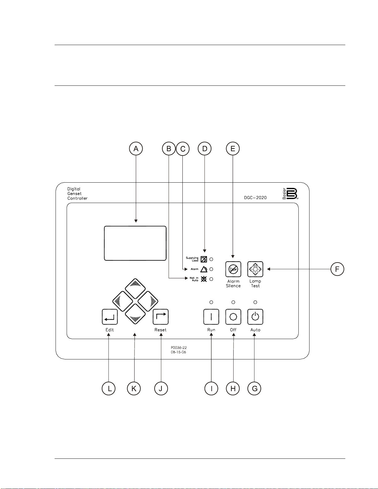
Figure 2-1 illustrates the front panel HMI of the DGC-2020. Table 2-1 lists the call-outs of Figure 2-1
along with a description of each HMI component.
Figure 2-1. Front Panel HMI
9400200990 Rev B DGC-2020 Human-Machi n e Interface 2-1
Page 24

Table 2-1. Front Panel HMI Descriptions
Locator Description
A Liquid Crystal Display. The backlit, 64 by 128 pixel LCD serves as the local information
source for metering, alarms, pre-alarms, and protective functions. Display operation is
maintained at -20°C. An optional LCD heater maintains display operation at -40°C.
B Not in Auto Indicator. This red LED lights when the DGC-2020 is not operating in Auto
mode.
C Alarm Indicator. This red LED lights continuously during alarm conditions and flashes
during pre-alarm conditions.
D Supplying Load Indicator. This green LE D lights when the generator current is greater
than EPS threshold current.
E Alarm Silence Pushbutton. Pressing this button opens the relay output programmed as
the horn output.
F Lamp Test Pushbutton. Pressing this button tests the DGC-2020 indicators by exercising
all LCD pixels and lighting all LEDs.
G Auto Pushb utton and Mode Indicator. Pressing the Auto button places the DGC-2020 in
Auto mode. The green Auto mode LED lights when Auto mode is active.
H Off Pushbutton and Mode Indicator. Pressing this button places the DGC-2020 in Off
mode. The red Off mode LED lights when the DGC-2020 is in Off mode.
I Run Pushbutton and Mode Indicator. Pressing this button places the DGC-2020 in Run
mode. The green Run mode LED lights when Run mode is active.
J Reset Pushbutton. This button is pressed to cancel a settings editing session and discard
any settings changes. When pressed, this button also resets the Breaker Management
Pre-Alarms.
K Arrow Pushbuttons. These four buttons are used to navigate through the front panel
display menus and modify settings.
The left- and right-arrow buttons are used to navigate through the menu levels. The right-
arrow button is pressed to move downward through the menu levels and the left-arrow
button is pressed to move upward.
Within a level, the up-arrow and down-arrow buttons are used to move among items
within the menu level. Pressing the down-arrow button moves to items lower in the list.
Pressing the up-arrow button moves to items higher in the list.
During a settings editing session, the up- and down-arrow buttons are used to raise and
lower the value of the selected setting.
L Edit Pushbutton. Pressing this button starts an editing session and enables changes to
DGC-2020 settings. At the conclusion of an editing session, the Edit pushbutton is
pressed again to save the setting changes.
DISPLAY OPERATION
The front panel display is used to make settings changes and display metering values. Refer to call-outs
J, K, and L in Table 2-1 for information on changing settings through the front panel and navigating
through the Metering screens.
Login and Permissions
Login To login, navigate to the SETTINGS, ENTER PASSWORD screen and press the Edit key. Use the
Up/Down arrow keys to scroll through the characters. Use the Left/Right arrow keys to enter more
characters. Once the password has been entered, press the Edit key to login. A LOGOUT selection now
appears in the list of SETTINGS. To logout, navigate to SETTINGS, LOGOUT and press the Edit key.
The LOGOUT selection is removed from the SETTINGS list.
2-2 DGC-2020 Human-Machine Interface 9400200990 Rev B
Page 25

Permissions
Communications access through the front panel will not be granted if communications access is active
through the modem or USB. In this case, the front panel will alternately display REMOTE COMMS,
FRONT PANEL IS READ ONLY and the summary screen. Remote access must be ended before gaining
access through the front panel.
Summary Screen and Configurable Metering
The summary screen can be set to standard or scrolling. When set to standard, only the following are
displayed:
• VOLT
• AMP
• PH
• Hz
• OIL
• FUEL
• TEMP
• BATT
When the summary screen is set to scrolling, you can select/configure the metering values that are
displayed. Up to 20 values can be displayed and these values will scroll at a delay time specified by the
user. To select a standard or scrolling summary, navigate to the SETTINGS, GENERAL SETTINGS,
FRONT PANEL HMI screen and edit the SUMMARY VIEW. The SCROLL DELAY setting is also found on
this screen.
To select the scrolling values, navigate to the SETTINGS, GENERAL SETTINGS, FRONT PANEL HMI
screen and edit the CONFIGURABLE METERING. The following values may be selected by the user to
be placed in the scrolling summary:
• NONE (Removes a line from the scrolling list)
• BLANK (Shows nothing on this line)
• OIL P
• TEMP
• BATT V
• RPM
• RPM SRC
• FUEL
• RUN HRS
• GEN VAB
• GEN VBC
• GEN VCA
• GEN VAN
• GEN VBN
• GEN VCN
• BUS Hz
• BUS V
• GEN Hz
• GEN PF
• GEN KWH
• GEN IA
• GEN IB
• GEN IC
• KW A
• KW B
• KW C
• KW TOT
• KVA A
• KVA B
• KVA C
9400200990 Rev B DGC-2020 Human-Machi n e Interface 2-3
Page 26

Sleep Mode
Sleep mode serves as a power saving feature. If the DGC-2020 is in Off mode or Auto mode not running
and a key is not pressed for more than 15 minutes, the front panel LCD backlight and LCD heater
(optional) are turned off. The DGC-2020 resumes normal display operation when any front panel button is
pressed or the genset is started remotely via the ATS input. If needed, Sleep mode can be permanently
disabled via BESTCOMSPlus or the front panel.
Changing a Setting
To change a setting, navigate to the setting you want to change and press the Edit key. If you are not
already logged in, you will be asked to enter your password at this time. Use the Up/Down arrows to raise
or lower the value. Press the Edit key again when finished.
Front Panel Display Structure
The front panel display begins with the SUMMARY SCREEN. Pressing the Right arrow key will open the
MAIN MENU screen. The MAIN MENU screen consists of METERING and SETTINGS. The METERING
screen branches are shown in Figure 2-2. The SETTINGS screen branches are shown in Figures 2-3
through 2-9.
2-4 DGC-2020 Human-Machine Interface 9400200990 Rev B
Page 27
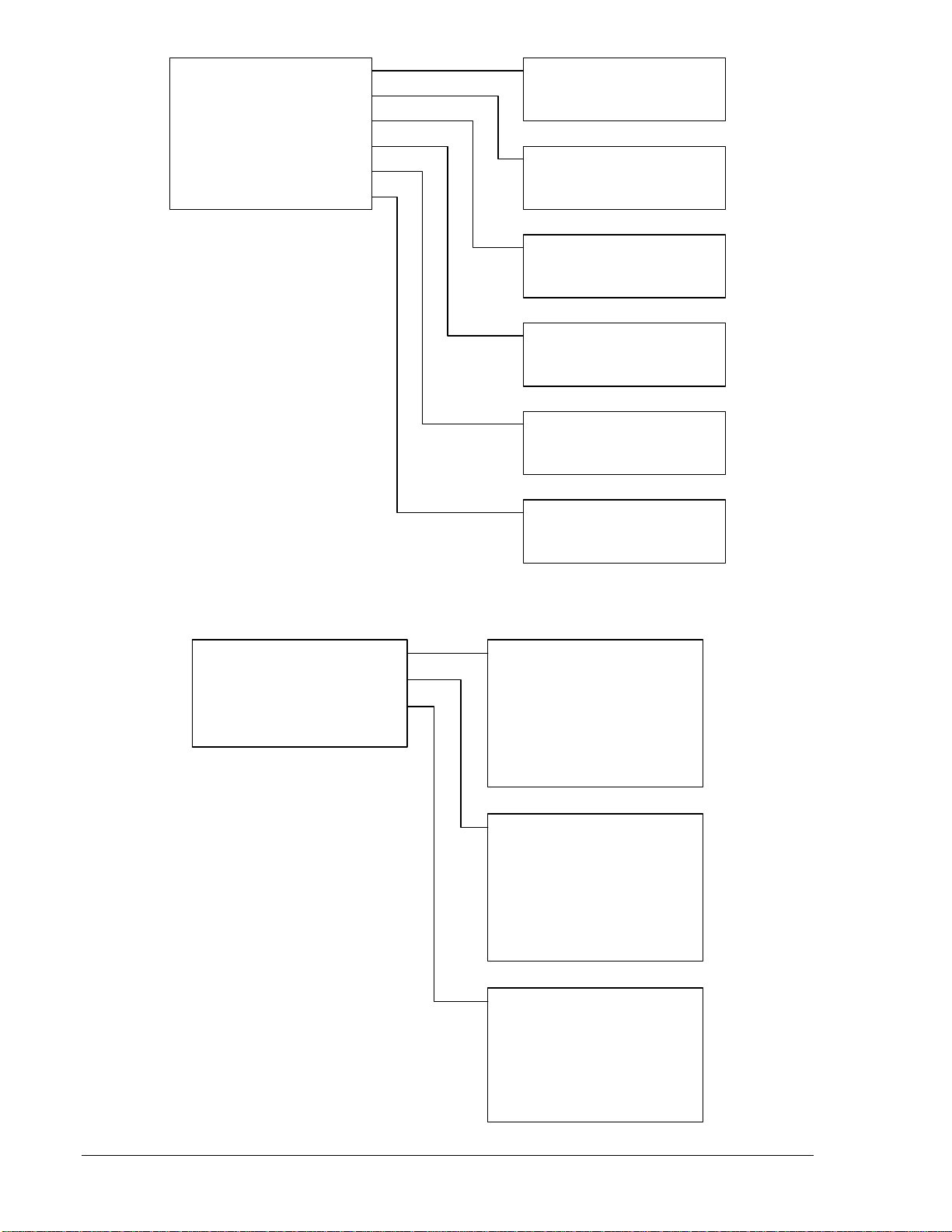
METERING
ENGINE
GENERATOR
POWER
RUN STATISTICS
ALARMS-STATUS
P0042-23
10-02-06
ENGINE
OIL PRESSURE
COOLANT TEMP
BATTERY VOLT
RPM
SPEED SRC
FUEL LEVEL
ENGINE LOAD
TOTAL RUN TM
HRS TO MAINT
GENERATOR
GEN VAB
GEN VBC
GEN VCA
GEN VAN
GEN VBN
GEN VCN
GEN FREQ
GEN AMPS A
GEN AMPS B
GEN AMPS C
BUS V
BUS FREQ
POWER
kW A
kW B
kW C
kW TOTAL
kVA A
kVA B
kVA C
kVA TOTAL
PF
CUMULATIVE
CUMULATIVE
TOTAL RUN TIME
LOADED RUN TIME
UNLOADED RUN TIME
SESSION
SESSION
TOTAL RUN TIME
LOADED RUN TIME
UNLOADED RUN TIME
STATUS
EPS SUPP. LOAD
GEN BREAKER
MAINS BREAKER
INPUTS
INPUT 1
INPUT 2
INPUT 3
INPUT 4
INPUT 5
INPUT 6
INPUT 7
INPUT 8
INPUT 9
INPUT 10
INPUT 11
INPUT 12
INPUT 13
INPUT 14
INPUT 15
INPUT 16
RUN STATISTICS
CUMULATIVE
SESSION
ALARMS-STATUS
ALARMS
PRE-ALARMS
STATUS
INPUTS
OUTPUTS
EVENT LOG
J1939 DATA
J1939 ENGINE CONFIG
J1939 ACTIVE DTC
J1939 PREV DTC
MDEC FAULT CODES
Figure 2-2. Metering Screen Branches
OUTPUTS
OUTPUT 1
OUTPUT 2
OUTPUT 3
OUTPUT 4
OUTPUT 5 (Optional)
OUTPUT 6 (Optional)
OUTPUT 7 (Optional)
OUTPUT 8 (Optional)
OUTPUT 9 (Optional)
OUTPUT 10 (Optional)
OUTPUT 11 (Optional)
OUTPUT 12 (Optional)
EVENT LOG
EVENT
EVENT
ACTIVE
OCCURRENCE COUNT
FIRST DATE
FIRST TIME
LAST DATE
LAST TIME
9400200990 Rev B DGC-2020 Human-Machi n e Interface 2-5
Page 28
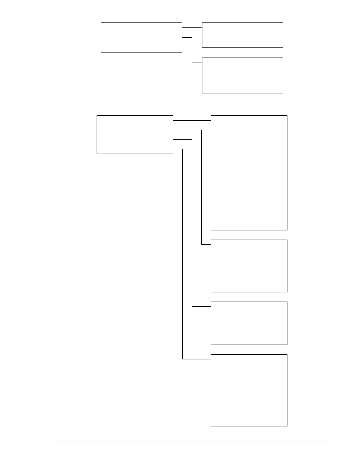
SETTINGS
GENERAL SETTINGS
GENERAL SETTINGS
COMMUNICATIONS
SYSTEM PARAMS
ALARM CONFIGURATION
GENERATOR PROTECTION
BREAKER MANAGEMENT
ENTER PASSWORD
P0042-24
09-27-06
Refer to Figure 2-4
COMMUNICATIONS
Refer to Figure 2-5
SYSTEM PARAMS
Refer to Figure 2-6
ALARM CONFIGURATION
Refer to Figure 2-7
GENERATOR PROTECTION
Refer to Figure 2-8
BREAKER MANAGEMENT
Refer to Figure 2-9
Figure 2-3. Settings Screen Branches
GENERAL SETTINGS
FRONT PANEL HMI
FRONT PANEL HMI
CONFIGURE DATE/TIME
VIEW DATE/TIME
VERSION INFO
P0042-25
09-27-06
Figure 2-4. General Settings Screen Branches
SUMMARY VIEW
SCROLL DELAY
LCD CONTRAST
SLEEP MODE
LANGUAGE
CONFIGURABLE METERING
CONFIGURE DATE/TIME
HOURS
MINUTES
SECONDS
MONTH
DAY
YEAR
VERSION INFO
FIRMWARE VERSION
BOOT CODE
SERIAL NUMBER
PART NUMBER
MODEL NUMBER
2-6 DGC-2020 Human-Machine Interface 9400200990 Rev B
Page 29
COMMUNICATIONS
CANBUS SETUP
CANBUS SETUP
CANBUS ENABLE
RS485 SETUP
P0042-26
09-27-06
RS485 SETUP
COMM BAUD
COMM PARITY
MODBUS ADDR
Figure 2-5. Communications Screen Branches
SYSTEM PARAMS
SYSTEM SETTINGS
CRANK SETTINGS
SENSING TRANS
ENGINE STATISTICS
P0042-27
09-27-06
SYSTEM SETTINGS
GEN CONNECT
RATED kW
RATED VOLTS
RATED FREQ
RATED RPM
COOLDWN TIME
EPS THRESHLD
FUEL LVL TYP
SYSTEM UNITS
BATTERY VOLT
FLYWHL TEETH
SPEED SOURCE
MAINT RESET
NFPA LEVEL
HORN
1 PHASE O-RIDE
CRANK SETTINGS
DISCNCT LMIT
PRECRNK DELY
PRESTRT CNTCT
STYLE
# CYCLES
CYCLE TIME
SENSING TRANS
GEN PT PRI V
GEN PT SEC V
GEN CT PRI A
BUS PT PRI V
BUS PT SEC V
ENGINE STATISTICS
START MONTH
START DAY
START YEAR
# STARTS
HRS TO MAINT
kW-Hrs
TOTAL HRS
LOADED HRS
UNLOADED HRS
Figure 2-6. System Params Screen Branches
9400200990 Rev B DGC-2020 Human-Machi n e Interface 2-7
Page 30
ALARM CONFIGURATION
PRE-ALARMS
ALARMS
SENDER FAIL
P0042-27
09-27-06
PRE-ALARMS
HIGH COOLANT TEMP
LOW COOLANT TEMP
LOW OIL PRESSURE
LOW FUEL LEVEL
ENGINE OVERLOAD
MAINTENANCE INTERVAL
BATTERY OVERVOLTAGE
LOW BATTERY VOLTAGE
WEAK BATTERY VOLTAGE
HIGH FUEL LEVEL
ENABLE and THRESHOLD settings
for High Coolant Temp, Low Coolant
Temp, Low Oil Pressure, Low Fuel
Level, Engine Overload, Maintenance
Interval, and Battery Overvoltage.
ENABLE, THRESHOLD, and
ACTIVTN DLY settings for Low
Battery Voltage, Weak Battery
Voltage, and High Fuel Level.
ALARMS
HIGH COOLANT TEMP
ENABLE, THRESHOLD, and
ARMING DELAY settings for High
Coolant Temp and Low Oil Pressure.
LOW OIL PRESSURE
LOW FUEL LEVEL
OVERSPEED
SENDER FAIL
COOL TEMP SENDR FAIL
OIL PRESS SENDR FAIL
ENABLE, THRESHOLD, and
ACTIVATN DELAY settings for Low
Fuel Level and Overspeed.
CONFIG TYPE and ACTIVATN DLY
settings for Cool Temp Sendr Fail, Oil
Press Sendr Fail, Fuel Levl Sendr
Fail, and Voltage Sense Fail.
FUEL LEVL SENDR FAIL
VOLTAGE SENSE FAIL
SPEED SENDR FAIL
TIME DELAY setting for Speed Sendr
Fail.
Figure 2-7. Alarm Configuration Screen Branches
2-8 DGC-2020 Human-Machine Interface 9400200990 Rev B
Page 31

GENERATOR PROTECTION
51 OVERCURRENT (Option)
27 UNDERVOLTAGE
59 OVERVOLTAGE
47 PHASE IMBALANCE (Option)
81 O/U FREQUENCY
P0042-29
09-27-06
51 OVERCURRENT
LOW LINE OVERRIDE
3 PHASE SETTINGS
1 PHASE SETTINGS
LOW LINE OVERRIDE
SCALE FACTOR
3 PHASE SETTINGS
PICKUP
TIME DIAL
CURVE
ALARM CONFIG
1 PHASE SETTINGS
PICKUP
TIME DIAL
CURVE
ALARM CONFIG
27 UNDERVOLTAGE
LOW LINE OVERRIDE
3 PHASE SETTINGS
1 PHASE SETTINGS
59 OVERVOLTAGE
LOW LINE OVERRIDE
3 PHASE SETTINGS
1 PHASE SETTINGS
47 PHASE IMBALANCE
PICKUP
TIME DELAY
ALARM CONFIG
LOW LINE OVERRIDE
SCALE FACTOR
3 PHASE SETTINGS
PICKUP
TIME DELAY
FREQ INHIBIT
ALARM CONFIG
1 PHASE SETTINGS
PICKUP
TIME DELAY
FREQ INHIBIT
ALARM CONFIG
LOW LINE OVERRIDE
SCALE FACTOR
3 PHASE SETTINGS
PICKUP
TIME DELAY
ALARM CONFIG
1 PHASE SETTINGS
PICKUP
TIME DELAY
ALARM CONFIG
81 O/U FREQUENCY
UNDERFREQUENCY
OVERFREQUENCY
UNDERFREQUENCY
INHIBIT VOLTS
PICKUP
TIME DELAY
ALARM CONFIG
OVERFREQUENCY
PICKUP
TIME DELAY
ALARM CONFIG
Figure 2-8. Generator Protection Screen Branches
9400200990 Rev B DGC-2020 Human-Machi n e Interface 2-9
Page 32

BREAKER MANAGEMENT
MAINS FAIL TRANSFER
BREAKER HARDWARE
BUS CONDITION DETECT
SYNCHRONIZER
AVR BIAS CONTROL
GOV BIAS CONTROL
P0042-30
09-29-06
MAINS FAIL TRANSFER
ENABLE
BREAKER HARDWARE
CLOSE WAIT TIME
GEN BREAKER
MAINS BREAKER
CLOSE WAIT TIME
TIME
GEN BREAKER
CONTINUOUS
OPEN PULSE
CLOSE PULSE
CLOSING TIME
MAINS BREAKER
CONFIGURED
BUS CONDITION DETECT
GEN DEAD
GEN STABLE
GEN FAILED
BUS DEAD
BUS STABLE
BUS FAILED
SYNCHRONIZER
TYPE
SLIP FREQ
REGUL OFFSET
CLOSNG ANGLE
VS>VD
TIME DELAY
FAIL DELAY
GEN DEAD
THRESHOLD
TIME DELAY
GEN STABLE
OV PICKUP
OV DROPOUT
UV PICKUP
UV DROPOUT
OF PICKUP
OF DROPOUT
UF PICKUP
UF DROPOUT
TIME DELAY
GEN FAILED
TIME DELAY
BUS DEAD
THRESHOLD
TIME DELAY
BUS STABLE
OV PICKUP
OV DROPOUT
UV PICKUP
UV DROPOUT
OF PICKUP
OF DROPOUT
UF PICKUP
UF DROPOUT
TIME DELAY
BUS FAILED
TIME DELAY
AVR BIAS CONTROL
CONTACT
GOV BIAS CONTROL
CONTACT
CONTACT
TYPE
CONTACT
TYPE
Figure 2-9. Breaker Management Screen Branches
2-10 DG C-2020 Human-M achi n e Interface 9400200990 Rev B
Page 33

REAR PANEL
All DGC-2020 terminals and connectors are located on the rear panel. Rear panel terminals and
connectors are illustrated in Figure 2-10. (To show the terminals and connectors, Figure 2-10 shows the
DGC-2020 with the rear cover removed.) Table 2-2 lists the call-outs of Figure 2-10 along with a
description of each connector type.
Figure 2-10. DGC-2020 Rear Panel HMI
Table 2-2. Rear Panel HMI Descriptions
Locator Description
A, D The majority of external, DGC-2020 wiring is terminated at 15-position connectors with
compression terminals. These connectors plug into headers on the DGC-2020. The
connectors and headers have a dovetailed edge that ensures proper connector
orientation. Each connector and header is uniquely keyed to ensure that a connector
mates only with the correct header. Connector screw terminals accept a maximum wire
size of 12 AWG.
B The mini-B USB socket mates with a standard USB cable and is used with a PC running
BESTCOMSPlus software for local communication with the DGC-2020.
C DGC-2020 controllers with an option al, internal, dial-out modem connect to a telephone
line through a USOC RJ-11 jack.
E Connections to the DGC-2020 Start (starter), Run (fuel solenoid), and Pre (glow plug)
output contacts are made directly to each relay through quarter-inch, male, quick-connect
terminals.
F An optional battery backup for the real-time clock is available when ordering.
9400200990 Rev B DGC-2020 Human-Machi n e Interface 2-11
Page 34

This page intentionally left blank.
2-12 DG C-2020 Human-M achi n e Interface 9400200990 Rev B
Page 35

SECTION 3 • FUNCTIONAL DESCRIPTION
TABLE OF CONTENTS
SECTION 3 • FUNCTIONAL DESCRIPTION...........................................................................................3-1
INTRODUCTION....................................................................................................................................3-1
DGC-2020 FUNCTION BLOCKS...........................................................................................................3-1
Power Supply ..................................................................................................................................... 3-1
Microprocessor...................................................................................................................................3-1
Generator Voltage Sensing Inputs..................................................................................................... 3-2
Bus Voltage Sensing Inputs...............................................................................................................3-2
Current Sensing Inputs.......................................................................................................................3-2
Analog Engine Sender Inputs.............................................................................................................3-2
Speed Signal Inputs...........................................................................................................................3-3
Contact Inputs .................................................................................................................................... 3-3
Front Panel HMI................................................................................................................................. 3-4
Remote Display Panel (Optional).......................................................................................................3-4
Communication Ports......................................................................................................................... 3-4
Output Contacts ................................................................................................................................. 3-8
BREAKER MANAGEMENT................................................................................................................... 3-8
Introduction......................................................................................................................................... 3-8
Determining Breaker Status...............................................................................................................3-9
Processing Breaker Requests............................................................................................................3-9
Breaker Operation.............................................................................................................................. 3-9
Figures
Figure 3-1. Function Block Diagram..........................................................................................................3-1
Tables
Table 3-1. ECU Parameters Obtained from CAN Interface ...................................................................... 3-5
Table 3-2. Engine Configuration Parameters Obtained from CAN Interface............................................ 3-6
Table 3-3. Diagnostic Information Obtained Over the CAN Interface....................................................... 3-7
9400200990 Rev B DGC-2020 Functional Description i
Page 36

This page intentionally left blank.
ii DGC-2020 Functional Description 9400200990 Rev B
Page 37

SECTION 3 • FUNCTIONAL DESCRIPTION
INTRODUCTION
This section describes how the DGC-2020 functions. A detailed description of each function block is
provided in the paragraphs under the heading of DGC-2020 Function Blocks.
DGC-2020 operating and metering features are described in Section 4, BESTCOMSPlus Software.
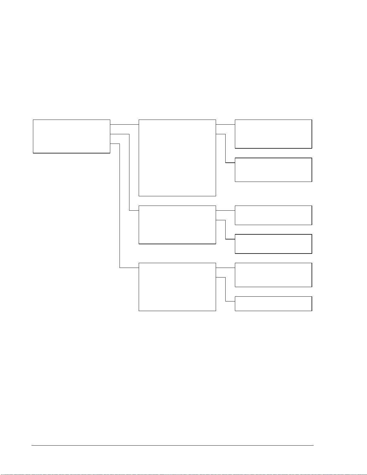
DGC-2020 FUNCTION BLOCKS
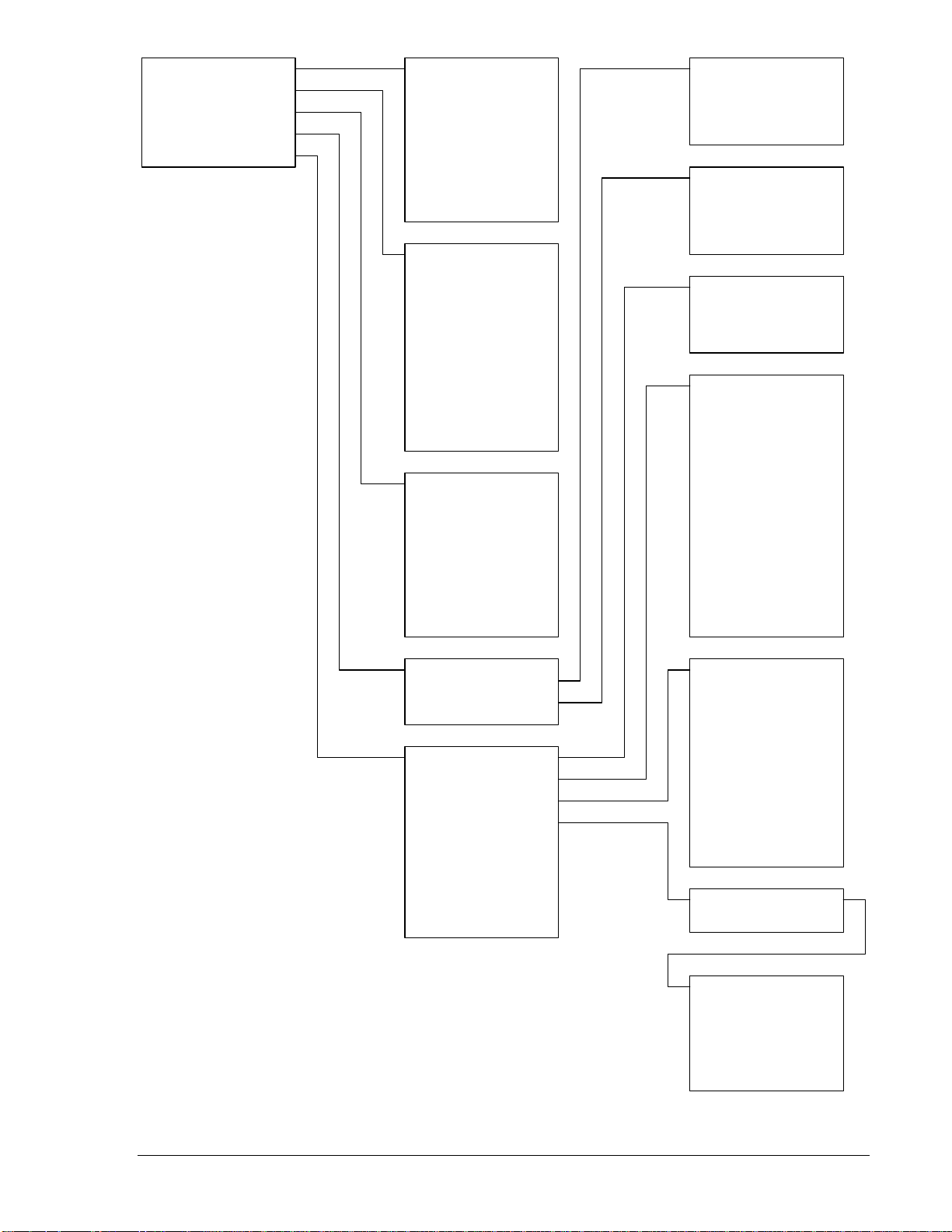
To ease understanding, DGC-2020 functions are illustrated in the block diagram of Figure 3-1. The
following paragraphs describe each function in detail.
Power Supply
(To Internal Circuitry)
Sensing
Battery Voltage Sensing
Sender Input Sensing
Generator Current Sensing
Bus Voltage Sensing
Front Panel HMI
and LCD
Remote Display
Panel Driver
(RDP-110)
HMI
Com Ports
Sensing
Generator Voltage Sensing
MPU Speed Sensing
Programmable Dry Contact Inputs (16)
USB Com Port
J1939 CAN Com Port
RS-485 Com Port (Optional)
Modem Com Port (Optional)
Emergency Stop Contact Input
Microprocessor
P0040-04
06-20-06
Programmable
Output Contacts
(4 or 12)
Fuel Solenoid
Output Contacts
Engine Crank
Output Contacts
Pre-start Output
Contacts
Output
Contacts
Figure 3-1. Function Block Diagram
Power Supply
The internal, switch-mode power supply uses the applied battery voltage to generate operating power for
the internal circuitry of the DGC-2020. The power supply accepts a nominal battery voltage of 12 or 24
Vdc and has an operating range of 6 to 32 Vdc. Battery voltage is applied to terminals 2 (–) and 3 (+).
Operating power must be of the correct polarity. Although reverse polarity will not cause damage, the
DGC-2020 will not operate.
Battery Voltage Sensing
Voltage applied to the power supply is filtered and reduced to a suitable level for sensing by the
microprocessor.
Microprocessor
The microprocessor controls the overall functionality of the DGC-2020 and makes decisions based on
programming and system inputs.
Circuits relating to the microprocessor inputs are described in the following paragraphs.
9400200990 Rev B DGC-2020 Functional Description 3-1
Page 38

Zero Crossing Detection
The zero crossing of A-phase to B-phase or A-phase to C-phase (user-selectable) line voltage is detected
and used to calculate the generator frequency. The zero crossing of A-phase to B-phase bus voltage is
used to calculate the bus frequency.
Analog-to-Digital Converter
Scaled and conditioned signals representing the sensing voltage, sensing current, coolant temperature,
fuel level, oil pressure, and battery voltage are digitized by the microprocessor’s analog-to-digital
converter. The digitized information is stored in random access memory (RAM) and used by the
microprocessor for all metering and protection functions.
Generator Voltage Sensing Inputs
Voltages applied to the generator voltage sensing inputs are scaled to levels suitable for use by the
internal circuitry. Generator voltage sensing configuration is menu-selectable.
The generator voltage sensing inputs accept a maximum voltage of 576 Vrms, line-to-line. Sensing
voltage is applied to terminals 41 (A-phase), 39 (B-phase), 37 (C-phase), and 35 (neutral).
Bus Voltage Sensing Inputs
Voltage applied to the bus voltage sensing input is scaled to a level suitable for use by the internal
circuitry.
The bus voltage sensing input accepts a maximum voltage of 576 Vrms. Sensing voltage is applied to
terminals 45 (A-phase) and 43 (B-phase).
Current Sensing Inputs
Generator currents are sensed and scaled to values suitable for use by the inte rnal circuitry.
DGC-2020 controllers with 1 ampere current sensing (style number 1xxxxxxxx) accept a maximum
current value of 1 Aac. DGC-2020 controllers with 5 ampere current sensing (style number 5xxxx xxxx)
accept a maximum current value of 5 Aac. Sensing current is applied to terminals 68 (IA–) and 69 (IA+),
71 (IB–) and 72 (IB+), and 74 (IC–) and 75 (IC+).
Analog Engine Sender Inputs
Programmable analog engine sender inputs give the DGC-2020 user the flexibility to select the engine
sender to be used in an application. Information about programming the sender inputs is provided in
Section 4, BESTCOMSPlus Software.
Oil Pressure
A current is provided to the oil pressure sender. The developed voltage is measured and scaled for use
by the internal circuitry. An open circuit or short circuit across the oil pressure sender terminals will cause
the DGC-2020 to indicate a failed sender. Oil pressure senders that are compatible with the DGC-2020
include Datcon model 02505-00, Isspro model R8919, and Stewart-Warner models 411K and 411M.
Other senders may also be used. BESTCOMSPlus software allows for the programming of sender
characteristics. See Section 4, BESTCOMSPlus Software, for more information.
Oil pressure sender connections are made at terminals 8 and 11 (sender co mmon).
Coolant Temperature
A current is provided to the coolant temperature sender. The developed voltage is measured and scaled
for use by the internal circuitry. An open circuit or short circuit across the coolant temperature sender
terminals will cause the DGC-2020 to indicate a failed sender. Coolant temperature senders that are
compatible with the DGC-2020 include Datcon model 02019-00, Faria model TS4042, Isspro model
R8959, and Stewart-Warner model 334P. Other senders may be used. BESTCOMSPlus software allows
for the programming of sender characteristics. See Section 4, BESTCOMSPlus Software, for more
information.
Coolant temperature sender connections are made at terminals 10 and 11 (sender common).
Fuel Level
A current is provided to the fuel level sender. The developed voltage is measured and scaled for use by
the internal circuitry. An open circuit or short circuit across the fuel level sender terminals will cause the
DGC-2020 to indicate a failed sender. Fuel level senders that are compatible with the DGC-2020 include
3-2 DGC-2020 Functional Description 9400200990 Rev B
Page 39

Isspro model R8925. Other senders may be used. BESTCOMSPlus software allows for the programming
of sender characteristics. See Section 4, BESTCOMSPlus Software, for more information.
Fuel level sender connections are made at terminals 9 and 11 (sender common).
Speed Signal Inputs
The DGC-2020 uses signals from the generator voltage sensing inputs and magnetic pickup input to
detect machine speed.
Generator Voltage Sensing Input
The generator voltage sensed by the DGC-2020 is used to measure frequency and can be used to
measure machine speed.
Sensing voltage is applied to terminals 41 (A-phase), 39 (B-phase), 37 (C-phase), and 35 (Neutral).
Magnetic Pickup Input (MPU)
Voltage supplied by a magnetic pickup is scaled and conditioned for use by the internal circuitry as a
speed signal source. The MPU input accepts a signal over the range of 3 to 35 volts peak and 32 to
10,000 hertz.
Magnetic pickup connections are provided at terminals 31 (+) and 32 (–).
Contact Inputs
The DGC-2020 has seventeen contact sensing inputs: an emergency stop input and 16 programmable
inputs. Additional contact inputs can be accommodated with separate I/O modules. Contact Basler
Electric for availability and ordering information.
Emergency Stop Input
This input accepts Form B, dry contacts. An open circuit at this continuously monitored input initiates an
emergency stop. An emergency stop removes operating power from the DGC-2020 Pre-Start, Run, and
Fuel output relays.
Emergency stop contact connections are made at terminals 46 and 47.
Programmable Inputs
Each programmable input (Input 1 through Input 16) can be independently configured to perform the
following functions. By default, each programmable input is disabled.
• Automatic Transfer Switch
• Battery Charger Fail
• Battle Override
• Fuel Leak Detection
• Grounded Delta Override
• Low Coolant Level
• Low-Line Override
• Single-Phase A-C Override
• Single-Phase Override
The programmable inputs accept normally open, Form A contacts. A contact is connected between a
programmable input and the negative side of the battery. Through BESTCOMSPlus, each programmable
contact input can be assigned a name (16 alphanumeric characters, maximum) and configured as an
alarm input, a pre-alarm input, or neither. The default names for the inputs are INPUT_x (where x = 1 to
16). When a programmable contact input is closed, the front panel display shows the name of the closed
input if it was programmed as an alarm or pre-alarm input. Alarm inputs are annunciated through the
Normal display mode screens of the front panel. Pre-alarm inputs are annunciated through the pre-alarm
metering screen of the front panel. If neither is programmed, no indication is given. Programming an input
as neither is useful when a programmable input is used as an input to programmable logic.
Connections for the programmable inputs are provided at terminals 15 (Input 16) through 30 (Input 1).
The negative side of the battery voltage (terminal 2) serves as the return connection for the
programmable inputs.
9400200990 Rev B DGC-2020 Functional Description 3-3
Page 40

Front Panel HMI
The front panel HMI provides a convenient interface for viewing system parameters and for controlling the
DGC-2020/generator set. Front panel HMI components include an LCD (liquid crystal display), LED (light
emitting diodes) indicators, and pushbuttons.
LCD
The backlit LCD provides metering, pre-alarm, and alarm information. Detailed information about the LCD
is provided in the Software Operation sub-section.
LED Indicators
The LEDs indicate pre-alarm and alarm conditions along with DGC-2020 status and generator status.
Pushbuttons
The pushbuttons are used to scroll through and select parameters displayed on the LCD, change
setpoints, start and stop the generator, and reset alarms.
Remote Display Panel (Optional)
Applications that require remote annunciation can use Basler Electric’s Remote Display Panel, RDP-110.
Using the RDP-110 with the DGC-2020 meets the requirements of NFPA Standard 110. The RDP-110
uses a dedicated, four-terminal interface with the DGC-2020. The RDP-110 communicates with the DGC2020 via terminals 6 (RDP TXD–) and 7 (RDP TXD+) and receives power from terminals 4 (RDP BATT+)
and 5 (RDP BATT-). Remote indication of many pre-alarm and alarm conditions is provided by the RDP-
110.
The following pre-alarm conditions are indicated by LEDs on the RDP-110 front panel:
• Battery charger failure ∗
• Battery overvoltage
• High coolant temperature
• Low coolant temperature
• Low fuel level
• Low oil pressure
• Weak battery
The following alarm conditions are indicated by LEDs and an audible alarm on the RDP-110 front panel:
• Low coolant level ∗
• High coolant temperature
• Low oil pressure
• Overcrank
• Overspeed
• Emergency stop
• Fuel leak/fuel sender failure ∗
• Engine sender unit failure
∗ Can be configured in the DGC-2020 as None, Alarm, or Pre-Alarm. See Section 4, BESTCOMSPlus,
Programmable Inputs, Programmable Functions, for more information. The light on the RDP-110 will turn
on when the input that is assigned to the programmable function is closed, whether the function is
configured as None, Alarm, or Pre-Alarm.
Additionally, the RDP-110 indicates when the DGC-2020 is not operating in Auto mode and when the
generator is supplying load. For more information about the RDP-110, request product bulletin SNE.
RDP-110 communication connections are made at DGC-2020 terminals 6 (RDP TXD–) and 7
(RDP TXD+). RDP-110 operating power is supplied at DGC-2020 terminals 4 (RDP BATT+) and 5 (RDP
BATT–).
Communication Ports
DGC-2020 communication ports include a USB jack, CAN terminals, optional RS-485 terminals, and an
optional modem jack.
USB
The rear-panel, mini-B USB socket enables local communication with a PC running BESTCOMSPlus
software. The DGC-2020 is connected to a PC using a standard USB cable. BESTCOMSPlus is a
3-4 DGC-2020 Functional Description 9400200990 Rev B
Page 41

Windows® based communication software package that is supplied with the DGC-2020. A detailed
description of BESTCOMSPlus is provided in Section 4, BESTCOMSPlus Software.
CANBus
A Control Area Network (CAN) is a standard interface that enables communication between multiple
controllers on a common network using a standard message protocol. DGC-2020 controllers have a CAN
interface that supports the SAE J1939 protocol and the MTU/MDEC protocol.
Applications using an engine-driven generator set controlled by a DGC-2020 may also have an Engine
Control Unit (ECU). The CAN interface allows the ECU and DGC-2020 to communicate. The ECU reports
operating information to the DGC-2020 through the CAN interface. Operating parameters and diagnostic
information, if supported by the ECU, are decoded and displayed for monitoring.
The primary use of the CAN interface is to obtain engine operating parameters for monitoring speed,
coolant temperature, oil pressure, coolant level, and engine hours without the need for direct connection
to individual senders. Table 3-1 lists the ECU parameters and Table 3-2 lists the engine configuration
parameters supported by the DGC-2020 CAN interface. These parameters are transmitted via the CAN
interface at preset intervals. See the column labeled Update Rate in Table 3-1 for transmission rates. This
information can also be transmitted upon user request.
CAN interface connections are made at 48 (CAN L), 49 (CAN H), and 50 (SHIELD).
Table 3-1. ECU Parameters Obtained from CAN Interface
ECU Parameter
Actual engine percent torque % % engine speed
Air filter differential pressure kPa psi 500 ms 100th 107
Air inlet temperature kPa
Ambient air temperature
Barometric pressure kPa psi 1 s 10th 108
Battery voltage Vdc Vdc 1 s 10th 168
Boost pressure kPa psi 500 ms none 102
Coolant level % % 500 ms 10th 111
Coolant pressure kPa psi 500 ms 10th 109
Engine coolant temperature
Engine intercooler temperature
Engine oil level % % 500 ms 10th 98
Engine oil pressure kPa psi 500 ms 10th 100
Engine oil temperature
Engine speed rpm rpm engine speed
Exhaust gas temperature
Fuel delivery pressure kPa psi 500 ms 10th 94
Fuel rate liter/hr gal/hr 100 ms 100th 183
Fuel temperature
Injection control pressure MPa psi 500 ms none 164
Injector metering rail pressure MPa psi 500 ms none 157
Intake manifold temperature
Percent load at current rpm % % 50 ms none 92
Switched battery voltage (at
ECU)
Throttle (accelerator pedal)
position
Total engine hours hours hours requested 1.5 s 100th 247
Total fuel used liters gallons requested 1.5 s none 250
Trip fuel liters gallons requested 1.5 s none 182
Metric
Units
°C °F
°C °F
°C °F
°C °F
°C °F
°C °F
°C °F
Vdc Vdc 1 s 10th 158
% % 50 ms 10th 91
English
Units
°F
Update Rate
dependent
1 s none 172
1 s 10th 171
1 s none 110
1 s none 52
1 s 10th 175
dependent
500 ms 10th 173
1 s none 174
500 ms none 105
Decimal
Place
none 513
none 190
∗
SPN
∗ SPN is suspect parameter number.
9400200990 Rev B DGC-2020 Functional Description 3-5
Page 42

Table 3-2. Engine Configuration Parameters Obtained from CAN Interface
ECU Parameter
Engine speed at high idle point 6 rpm rpm 5 s none 532
Engine speed at idle point 1 rpm rpm 5 s none 188
Engine speed at point 2 rpm rpm 5 s none 528
Engine speed at point 3 rpm rpm 5 s none 529
Engine speed at point 4 rpm rpm 5 s none 530
Engine speed at point 5 rpm rpm 5 s none 531
Gain (Kp) of endspeed governor %/rpm %/rpm 5 s 100th 545
Maximum momentary engine override
speed point 7
Maximum momentary engine override time
limit
Percent torque at idle point 1 % % 5 s none 539
Percent torque at point 2 % % 5 s none 540
Percent torque at point 3 % % 5 s none 541
Percent torque at point 4 % % 5 s none 542
Percent torque at point 5 % % 5 s none 543
Reference engine torque
Requested speed control range lower limit rpm rpm 5 s none 535
Requested speed control range upper limit rpm rpm 5 s none 536
Requested torque control range lower limit % % 5 s none 537
Requested torque control range upper limit % % 5 s none 538
Metric
Units
rpm rpm 5 s none 533
seconds seconds 5 s 10th 534
N•m
English
Units
ft-lb 5 s none 544
Update
Rate
Decimal
Place
∗
SPN
∗ SPN is suspect parameter number.
CAUTION
When the CAN interface is enabled, the DGC-2020 will ignore the following
sender inputs: oil pressure, coolant temperature, and magnetic pickup.
Diagnostic Trouble Codes (DTCs)
The DGC-2020 obtains diagnostic engine information from a compatible engine control unit (ECU). The
DGC-2020 will receive an unsolicited message of a currently active diagnostic trouble code (DTC).
Previously active DTCs are available upon request. Active and previously active DTCs can be cleared on
request. Table 3-3 lists the diagnostic information that the DGC-2020 obtains over the CAN interface.
DTCs are reported in coded diagnostic information that includes the Suspect Parameter Number (SPN),
Failure Mode Identifier (FMI), and Occurrence Count (OC). All parameters have an SPN and are used to
display or identify the items for which diagnostics are being reported. The FMI defines the type of failure
detected in the subsystem identified by an SPN. The reported problem may not be an electrical failure but
a subsystem condition needing to be reported to an operator or technician. The OC contains the number
of times that a fault has gone from active to previously active.
3-6 DGC-2020 Functional Description 9400200990 Rev B
Page 43

Table 3-3. Diagnostic Information Obtained Over the CAN Interface
Transmission
Parameter
Repetition Rate
Active diagnostic trouble code 1 s
Lamp status 1 s
Previously active diagnostic trouble code On request
Request to clear active DTCs On request
Request to clear previously active DTCs On request
MTU MDEC ECU Fault Codes
A DGC-2020 connected to a genset equipped with an MTU MDEC engine controller tracks and displays
the active fault codes issued by the MDEC ECU. Active MDEC ECU fault codes can be viewed through
BESTCOMSPlus by using the Metering Explorer to expand the MTU MDEC tree or through the front
panel display by navigating to METERING, ALARMS-STATUS, MDEC FAULT CODES.
Each fault code is displayed with a fault description and the fault number. If the DGC-2020 does not have
descriptive information about a fault number that was received, the fault description will display as “NO
TEXT AVAILABLE”. For more detailed information, refer to your MDEC ECU documentation.
3, L1 T-FUEL
5, L1 T-CHRG AIR
9, L1 T-INTERCOOLER
15, L1 P-LUBE OIL
16, L2 P-LUBE OIL
19, L1 T-EXHAUST A
21, L1 T-EXHAUST B
23, L1 COOLANT LEVEL
24, L2 COOLANT LEVEL
30, ENGINE OVERSPEED
31, CHRGR1 OVERSPD 1
32, CHRGR1 OVERSPD 2
33, L1 P-FUELFLT DIF
44, L1 LEVEL INTRCLR
45, L2 LEVEL INTRCLR
51, L1 T-LUBE OIL
57, L1 P-COOLANT
58, L2 P-COOLANT
63, L1 P-CRANKCASE
65, L1 P-FUEL
67, L1 T-COOLANT
68, L2 T-COOLANT
69, L1 T-EXTERN 1
70, L2 T-EXTERN 1
71, L1 T-EXTERN 2
72, L2 T-EXTERN 2
73, L1 P-EXTERN 1
74, L2 P-EXTERN 1
75, L1 P-EXTERN 2
76, L2 P-EXTERN 2
77, LIN EXT CLNT LEV
78, LIN INTERCLR LEV
79, L BIN-EXTERN 3
80, L BIN-EXTERN 4
90, IDLE SPEED LOW
91, RUNUP SPEED LOW
92, START SPEED LOW
93, PREHT TMP. LIM 2
94, PREHT TMP. LIM 1
100, EDM NOT VALID
101, IDM NOT VALID
102, INVLD FUEL CNS 1
103, INVLD FUEL CNS 2
104, OP HRS1 INVALID
105, OP HRS2 INVALID
106, ERR REC1 INVALID
107, ERR REC2 INVALID
118, L1 SPPLY VOLT LO
119, L2 SPPLY VOLT LO
120, L1 SPPLY VOLT HI
121, L2 SPPLY VOLT HI
122, L1 T-ELECTRONIC
134, 15V POSECU DEFCT
136, 15V NEGECU DEFCT
137, L1 5V BUFFR TEST
138, SENSOR PWR DEFCT
139, L1 TE BUFFR TEST
140, TE BUF ECU DEFCT
142, BANK1ECU DEFECT
144, BANK2ECU DEFECT
145, 15V GOODECU DFCT
147, AD-TST1ECU DEFCT
149, AD-TST2ECU DEFCT
151, AD-TST3ECU DEFCT
170, MI MODULE FAIL
171, MI NOT ACTIVE
172, TBO EXPIRED
173, MODL WRITE LIMIT
180, CAN1 NODE LOST
181, CAN2 NODE LOST
183, CAN NO PU-DATA
184, CAN PUDATA EE-FL
185, CAN LESS MAILBXS
186, CAN1 BUS OFF
187, CAN1 ERROR PASSV
188, CAN2 BUS OFF
189, CAN2 ERROR PASSV
201, SD T-COOLANT
202, SD T-FUEL
203, SD T-CHARGE AIR
205, SD T-CLNT INTERC
208, SD P-CHARGE AIR
211, SD P-LUBE OIL
214, SD P-CRANKCASE
215, SD P-RAIL FUEL
216, SD T-LUBE OIL
220, SD COOLANT LEVEL
222, SD LVL LKG FUEL
223, SD LVL INTERCLR
230, SD CRANKSHFT SPD
231, SD CAMSHAFT SPD
245, SD POWER SUPPLY
246, SD T-ELECTRONIC
249, SD CAN STOP
250, SD CAN SPD DEMND
251, SD CAN UP/DOWN
252, SD CAN NOTCH POS
253, SD CAN OVERRIDE
254, SD CAN TST OVRSP
260, SD 15V POS SPPLY
261, SD 15V NEG SPPLY
262, SD 5V BUFFR TEST
263, SD TE BUFFR TEST
264, SD BANK 1 TEST
265, SD BANK 2 TEST
266, SD SPD DEMAND AN
267, SD SPDMTEST BNCH
269, SD LOAD PLS ANLG
271, SD T-EXTERN 1
272, SD T-EXTERN 2
273, SD P-EXTERN 1
274, SD P-EXTERN 2
275, MD EXT.CLNT LVL
276, MD INTERCLER LVL
277, MISDATA BIN-EXT3
278, MISDATA BIN-EXT4
279, SD CANRES TRIPFL
280, SD CAN ALRM RST
281, SD ADTEST1 SPPLY
282, SD ADTEST2 SPPLY
283, SD ADTEST3 SPPLY
284, SD CAN LAMP TEST
9400200990 Rev B DGC-2020 Functional Description 3-7
Page 44

RS-485 (Optional)
DGC-2020 controllers with the optional RS-485 communication port (style number xxxRxxxxx) can be
monitored and controlled via a polled network using the Modbus
®
protocol. The RS-485 port supports a
user-selectable baud rate of 1200, 2400, 4800, or 9600. Odd, even, or no parity is supported. Fixed
communication settings include the number of data bits (8) and stop bits (1). Modbus register values for
the DGC-2020 are listed and defined in Appendix B, Modbus Communication. RS-485 port connections
are made at DGC-2020 terminals 14 (485A), 13 (485B), and 12 (485 SHIELD).
Modem (Optional)
When equipped with the optional, internal, dial-out modem (style number xxxxxMxxx for US version or
xxxxxIxxx for international version), the DGC-2020 can be connected to a standard telephone line through
its RJ-11 jack. The modem enables the DGC-2020 to dial up to four pager telephone numbers and
annunciate conditions selected by the user. These conditions include any DGC-2020 alarm or pre-alarm,
closure of any programmable contact input, and an active cooldown timer. The modem accommodates
pagers that use seven data bits with even parity or modems using eight data bits with no parity.
Output Contacts
Output contact operation is controlled by the operating mode of the DGC-2020. The state of the
Emergency Stop contact input also affects output contact operation. When the Emergency Stop contact
input is open (emergency stop condition), the Pre-Start, Crank, and Fuel outputs open. When the
Emergency Stop input is closed, all output contacts operate normally.
DGC-2020 output contacts include Pre-Start, Crank, Fuel, and up to 12 programmable outputs. Additional
output contacts can be accommodated with separate I/O modules. Contact Basler Electric for availability
and ordering information.
Pre-Start
This output closes to energize the engine glow plugs. The Pre-Start output can be programmed to close
up to 30 seconds prior to engine cranking. The Pre-Start output can also be programmed to open upon
engine startup or remain closed as long as the engine is operating.
Pre-Start output connections are made through terminals located on the Pre-Start relay.
Crank
This output closes when engine cranking is initiated by the DGC-2020 and opens when the magnetic
pickup (MPU) or generator frequency indicates that the engine has started. Prior to engine starting, the
duration of cranking is determined by the cranking style (cycle or continuous) selected. Cycle cranking
permits up to 7 crank cycles with crank cycle duration of 5 to 15 seconds. The continuous crank time is
adjustable from 1 to 60 seconds.
Crank output connections are made through terminals located on the Crank rela y.
Fuel
This output closes when engine cranking is initiated by the DGC-2020. The Fuel output remains closed
until an off command or emergency stop command is received.
Fuel output connections are made through terminals located on the Fuel relay.
Programmable
DGC-2020 controllers with a style number of xxAxxxxxx have four programmable output contacts (OUT 1
through 4). Twelve programmable outputs (OUT 1 through 12) are provided on controllers with a style
number of xxBxxxxxx.
BREAKER MANAGEMENT
Introduction
The DGC-2020 is capable of controlling the generator breaker and the mains breaker. Once it is
determined that a valid breaker request is available, the DGC-2020 will attempt to operate the breaker if
possible. The user can choose to control only the generator breaker, the generator and mains breakers,
or none. BESTCOMSPlus is used to configure breaker management. Refer to Section 4,
BESTCOMSPlus Software, Breaker Management, for setting information.
3-8 DGC-2020 Functional Description 9400200990 Rev B
Page 45

Determining Breaker Status
The status of the breakers is determined by using BESTlogic+ Programmable Logic to setup the
GENBRK and MAINSBRK logic blocks. These logic blocks have outputs that can be configured to
energize an output contact and control a breaker as well as inputs for breaker control and status.
Processing Breaker Requests
Types of breaker operate requests include:
• Local Request - generated by internal functions and based on operating modes.
• Com Request - generated through a communication port using BESTCOMSPlus or the front panel
HMI.
• Logic Request - generated from the PLC (programmable logic controller).
The type of response given for a local request depends on the operating mode of the DGC-2020. When in
RUN mode, the generator and mains breakers can be closed manually. If operating in the OFF mode, the
generator breaker cannot be closed because the generator will not be stable. The generator and mains
breakers cannot be controlled manually when operating in AUTO mode. When in AUTO mode, the mains
fail feature will automatically control the breakers or the external ATS (automatic transfer switch) will start
the generator and control the breakers itself.
If the DGC-2020 is operating in Auto-Run mode, only local requests are considered.
Breaker Operation
The DGC-2020 will attempt to close a breaker only after verifying that it can be closed. If the breaker
cannot be closed, the close request will be ignored. Only one breaker can be closed at a time.
Synchronization is required before closing the breaker to a live bus. Closure to a dead bus can be
performed after meeting dead bus threshold and timing requirements set by the user.
Determining if it is Acceptable to Close a Breaker
Before the generator breaker can be closed, it must be configured in BESTCOMSPlus. If only the
generator breaker is configured (mains breaker not configured) the DGC-2020 looks at user settings to
determine if the generator side of the breaker is stable and the bus side is stable or dead. If both the
generator and the mains breakers are configured and open, the DGC-2020 will close the generator
breaker if the generator side of the breaker is stable. If both breakers are configured and the mains
breaker is closed, the DGC-2020 will close the generator breaker after verifying that both sides of the
generator breaker are stable and the DGC-2020 is synchronizing.
Before the mains breaker can be closed, is must be configured in BESTCOMSPlus. If both the mains and
the generator breakers are configured and open, the DGC-2020 will close the mains breaker if the mains
side of the breaker is stable. If both breakers are configured and the generator breaker is closed, the
DGC-2020 will close the mains breaker after verifying that both sides of the mains breaker are stable.
Changing the Breaker State
Synchronization is required when closing a breaker to a live bus. Bus conditions act as a supervisory
control over the synchronizing function. If synchronization is in process and either bus goes unstable,
synchronization is suspended. To close the breaker on a dead bus, the DGC-2020 generates a breaker
close request. The closing function is then run without synchroniza tion.
The GENBRK and MAINSBRK logic blocks contain both Open and Close logic outputs that can be
configured to energize an output contact, which would in turn operate the breaker. The Synchronizer
screen in BESTCOMSPlus is used to set the output contact type to pulses or continuous.
9400200990 Rev B DGC-2020 Functional Description 3-9
Page 46

This page intentionally left blank.
3-10 DGC-2020 Functional Description 9400200990 Rev B
Page 47

SECTION 4 • BESTCOMSPlus SOFTWARE
TABLE OF CONTENTS
SECTION 4 • BESTCOMSPlus SOFTWARE...........................................................................................4-1
INTRODUCTION....................................................................................................................................4-1
INSTALLATION......................................................................................................................................4-1
Installing BESTCOMSPlus................................................................................................................. 4-2
STARTUP AND ACTIVATION...............................................................................................................4-2
Starting BESTCOMSPlus...................................................................................................................4-2
Activating the DGC-2020 Plug-In....................................................................................................... 4-3
COMMUNICATION................................................................................................................................4-4
Connecting the DGC-2020 and PC....................................................................................................4-4
Configuring Communication............................................................................................................... 4-4
Installing the USB Driver if Automatic Installation Fails ..................................................................... 4-5
Establishing Communication.............................................................................................................. 4-5
MENU BARS.......................................................................................................................................... 4-5
Upper Menu Bar (BESTCOMSPlus Shell).........................................................................................4-5
Lower Menu Bar (DGC-2020 Plug-In)................................................................................................4-6
SETTINGS EXPLORER ........................................................................................................................4-7
DGC-2020 AND SYSTEM PARAMETERS ...........................................................................................4-7
GENERAL SETTINGS...........................................................................................................................4-7
Front Panel HMI................................................................................................................................. 4-7
Style Number...................................................................................................................................... 4-8
Device Information .............................................................................................................................4-8
Device Security Setup........................................................................................................................ 4-9
COMMUNICATIONS ...........................................................................................................................4-10
CANBus............................................................................................................................................4-10
Modem Setup (Optional)..................................................................................................................4-12
RS-485 (Optional) ............................................................................................................................4-13
SYSTEM PARAMETERS ....................................................................................................................4-14
System Settings ............................................................................................................................... 4-14
Crank Settings..................................................................................................................................4-15
Sensing Transformers...................................................................................................................... 4-16
PROGRAMMABLE INPUTS................................................................................................................ 4-17
Configurable Inputs.......................................................................................................................... 4-17
Programmable Functions.................................................................................................................4-18
PROGRAMMABLE OUTPUTS............................................................................................................4-19
Configurable Outputs .......................................................................................................................4-19
ALARM CONFIGURATION .................................................................................................................4-20
Pre-Alarms........................................................................................................................................4-20
Alarms ..............................................................................................................................................4-22
Sender Fail.......................................................................................................................................4-23
GENERATOR PROTECTION..............................................................................................................4-24
Voltage Protection............................................................................................................................ 4-24
Frequency Protection.......................................................................................................................4-26
Overcurrent Protection.....................................................................................................................4-27
BREAKER MANAGEMENT................................................................................................................. 4-28
Breaker Hardware............................................................................................................................4-28
Bus Condition Detection...................................................................................................................4-29
Automatic Synchronizer (Optional) ..................................................................................................4-30
PROGRAMMABLE SENDERS............................................................................................................ 4-32
BESTlogic+ PROGRAMMABLE LOGIC .......................................................................................... 4-32
Logic Timers.....................................................................................................................................4-33
FILE MANAGEMENT...........................................................................................................................4-33
Settings Files....................................................................................................................................4-33
Uploading Firmware Files.................................................................................................................4-34
Uploading Language Modules..........................................................................................................4-35
METERING EXPLORER .....................................................................................................................4-36
9400200990 Rev B DGC-2020 BESTCOMSPlus Software i
Page 48

Engine ..............................................................................................................................................4-38
Generator .........................................................................................................................................4-38
Power ...............................................................................................................................................4-38
Run Statistics....................................................................................................................................4-39
Status ...............................................................................................................................................4-39
Inputs................................................................................................................................................4-40
Outputs.............................................................................................................................................4-40
Alarms ..............................................................................................................................................4-41
Event Log .........................................................................................................................................4-41
J1939 ECU.......................................................................................................................................4-42
MTU MDEC......................................................................................................................................4-43
Summary..........................................................................................................................................4-44
Control..............................................................................................................................................4-45
Real Time Clock...............................................................................................................................4-45
UPDATING BESTCOMSPlus SOFTWARE.........................................................................................4-46
Figures
Figure 4-1. Typical User Interface Components........................................................................................4-1
Figure 4-2. BESTCOMSPlus Select Language Screen ............................................................................ 4-2
Figure 4-3. BESTCOMSPlus Splash Screen ............................................................................................4-3
Figure 4-4. BESTCOMSPlus Select New Device Screen.........................................................................4-3
Figure 4-5. Device Needs Activated Screen ............................................................................................. 4-4
Figure 4-6. DGC-2020 Connection Screen ............................................................................................... 4-4
Figure 4-7. Processing, Please Wait… Screen.........................................................................................4-5
Figure 4-8. BESTCOMSPlus Front Panel HMI Settings............................................................................4-8
Figure 4-9. BESTCOMSPlus DGC-2020 Style Chart Selections and Definitions.....................................4-8
Figure 4-10. BESTCOMSPlus Device Information Values and Settings...................................................4-9
Figure 4-11. BESTCOMSPlus Device Security Setup ............................................................................4-10
Figure 4-12. BESTCOMSPlus CANBus Setup........................................................................................4-11
Figure 4-13. BESTCOMSPlus Modem Setup .........................................................................................4-13
Figure 4-14. BESTCOMSPlus RS-485 Port Settings..............................................................................4-13
Figure 4-15. BESTCOMSPlus System Settings......................................................................................4-15
Figure 4-16. BESTCOMSPlus Engine Cranking Settings.......................................................................4-16
Figure 4-17. BESTCOMSPlus Sensing Transformers Parameters......................................................... 4-17
Figure 4-18. BESTCOMSPlus Configurable Inputs Settings...................................................................4-18
Figure 4-19. BESTCOMSPlus Settings for Programmable Functions.................................................... 4-19
Figure 4-20. BESTCOMSPlus Configurable Outputs Settings................................................................ 4-20
Figure 4-21. BESTCOMSPlus Pre-Alarms Settings................................................................................4-22
Figure 4-22. BESTCOMSPlus Alarms Settings.......................................................................................4-23
Figure 4-23. BESTCOMSPlus Sender Fail Settings ...............................................................................4-24
Figure 4-24. BESTCOMSPlus Voltage Protection Settings .................................................................... 4-26
Figure 4-25. BESTCOMSPlus Frequency Protection Settings ...............................................................4-27
Figure 4-26. BESTCOMSPlus Overcurrent Protection Settings .............................................................4-28
Figure 4-27. BESTCOMSPlus Breaker Hardware Settings.....................................................................4-29
Figure 4-28. BESTCOMSPlus Bus Condition Detection Settings........................................................... 4-30
Figure 4-29. BESTCOMSPlus Synchronizer Settings.............................................................................4-31
Figure 4-30. BESTCOMSPlus Programmable Senders Settings............................................................ 4-32
Figure 4-31. Settings Compare Setup.....................................................................................................4-34
Figure 4-32. Settings Compare View.......................................................................................................4-34
Figure 4-33. DGC-2020 Selection Screen............................................................................................... 4-35
Figure 4-34. Upload Firmware Screen .................................................................................................... 4-35
Figure 4-35. Language Module Upload Manager Screen....................................................................... 4-36
Figure 4-36. Docking Options..................................................................................................................4-37
Figure 4-37. Metering, Engine.................................................................................................................4-38
Figure 4-38. Metering, Generator............................................................................................................ 4-38
Figure 4-39. Metering, Power..................................................................................................................4-38
Figure 4-40. Metering, Run Statistics......................................................................................................4-39
Figure 4-41. Metering, Status.................................................................................................................. 4-39
Figure 4-42. Metering, Inputs ..................................................................................................................4-40
Figure 4-43. Metering, Outputs................................................................................................................4-40
Figure 4-44. Metering, Alarms................................................................................................................. 4-41
ii DGC-2020 BESTCOMSPlus Software 9400200990 Rev B
Page 49

Figure 4-45. Metering, Event Log............................................................................................................4-41
Figure 4-46. Metering, ECU Data............................................................................................................4-42
Figure 4-47. Metering, Engine Configuration ..........................................................................................4-42
Figure 4-48. Metering, Download DTC.................................................................................................... 4-43
Figure 4-49. Metering, MDEC Alarms ..................................................................................................... 4-43
Figure 4-50. Metering, MDEC Fault Codes............................................................................................. 4-43
Figure 4-51. Metering, Summary............................................................................................................. 4-44
Figure 4-52. Metering, Control.................................................................................................................4-45
Figure 4-53. Metering, Real Time Clock.................................................................................................. 4-45
Tables
Table 4-1. System Requirements for BESTCOMSPlus and the .NET Framework...................................4-2
Table 4-2. Explanation of Call-Outs on Figure 4-36................................................................................ 4-37
9400200990 Rev B DGC-2020 BESTCOMSPlus Software iii
Page 50

This page intentionally left blank.
iv DGC-2020 BESTCOMSPlus Software 9400200990 Rev B
Page 51

SECTION 4 • BESTCOMSPlus SOFTWARE
INTRODUCTION
BESTCOMSPlus is a Windows®-based, PC application that provides a user-friendly, graphical user
interface (GUI) for use with Basler Electric communicating products. The name BESTCOMSPlus is an
acronym that stands for B
ettings.
S
BESTCOMSPlus provides the user with a point-and-click means to set and monitor the DGC-2020. The
capabilities of BESTCOMSPlus make the configuration of one or several DGC-2020 controllers fast and
efficient. A primary advantage of BESTCOMSPlus is that a settings scheme can be created, saved as a
file, and then uploaded to the DGC-2020 at the user’s convenience.
BESTCOMSPlus uses plug-ins allowing the user to manage several different Basler Electric products.
The DGC-2020 is a plug-in for BESTCOMSPlus and must be activated before use.
The DGC-2020 plug-in opens inside the BESTCOMSPlus main shell with the same default logic scheme
that is shipped with the DGC-2020. This gives the user the option of developing a custom setting file by
modifying the default logic scheme or by building a unique scheme from scratch.
BESTlogic+ Programmable Logic is used to program DGC-2020 inputs and outputs, alarms, and
generator protection functions. This is accomplished by the drag-and-drop method. The user can drag
elements, components, inputs, and outputs onto the program grid and make connections between them
to create the desired logic scheme.
Figure 4-1 illustrates the typical user interface components of the DGC-2020 plug-in with
BESTCOMSPlus.
asler Electric Software Tool for Communications, Operations, Maintenance, and
Upper Menu Bar
Lower Menu Bar
Metering Explorer
Settings Explorer
Setting Information
Status Bar
Figure 4-1. Typical User Interface Components
10-11-06
P0038-25
INSTALLATION
BESTCOMSPlus software is built on the Microsoft® .NET Framework. The setup utility that installs
BESTCOMSPlus on your PC also installs the DGC-2020 plug-in and the .NET Framework.
BESTCOMSPlus operates with IBM-compatible personal computers (PCs) using Windows
Professional with SP4, Windows
XP Home with SP2, Windows
®
2000 Server with SP4, Windows® XP Professional with SP2, Windows®
®
XP Media Center with SP2, and Windows™ Server 2003. Microsoft®
9400200990 Rev B DGC-2020 BESTCOMSPlus Software 4-1
®
2000
Page 52

Internet Explorer 5.01 or later must be installed on your PC before installing BESTCOMSPlus. System
requirements for the .NET Framework and BESTCOMSPlus are listed in
Table 4-1. System Requirements for BESTCOMSPlus and the .NET Framework
Component Required Recommended
Processor 400 MHz 800 MHz or higher
RAM 96 MB 256 MB or above
Hard Drive
In order to install and run BESTCOMSPlus, a Windows user must have administrator rights. A Windows
user with limited rights may not be permitted to save files in certain folders.
Installing BESTCOMSPlus
1. Insert the BESTCOMSPlus CD-ROM into the PC CD-ROM drive.
2. When the BESTCOMSPlus Setup and Documentation CD menu appears, click the Install button for
the BESTCOMSPlus application. The setup utility automatically installs BESTCOMSPlus, the .NET
Framework, and the DGC-2020 plug-in for BESTCOMSPlus on your PC. If the .NET Framework is
already installed on your PC, the setup utility will not overwrite it. However, you should verify that you
have the latest version of the .NET Framework at
When BESTCOMSPlus installation is complete, a Basler Electric folder is added to the Windows
programs menu. This folder is accessed by clicking the Windows Start button and then accessing the
Basler Electric folder in the Programs menu. The Basler Electric folder contains an icon that, when
clicked, starts BESTCOMSPlus.
25 MB free (if .NET Framework is already installed on PC.) 50 MB or more
250 MB free (if .NET Framework is not already installed on PC.) 300 MB or more
www.microsoft.com.
Table 4-1.
STARTUP AND ACTIVATION
Starting BESTCOMSPlus
To start BESTCOMSPlus, click the Start button, Programs, Basler Electric, and then the BESTCOMSPlus
icon. During initial startup, the BESTCOMSPlus Select Language screen is displayed (
can select to have this screen displayed each time BESTCOMSPlus is started, or you can select a
preferred language and this screen will be bypassed in the future. Click OK to continue. This screen can
also be accessed by selecting T
The BESTCOMSPlus splash screen is shown for a brief time. See
ools and Select Language from the menu bar.
Figure 4-2. BESTCOMSPlus Select Language Screen
Figure 4-3.
Figure 4-2). You
4-2 DGC-2020 BESTCOMSPlus Software 9400200990 Rev B
Page 53

Figure 4-3. BESTCOMSPlus Splash Screen
The BESTCOMSPlus platform window opens. If a DGC-2020 is connected, select N
ommunication pull-down menu and select DGC-2020. See Figure 4-4. The DGC-2020 plug-in is
the C
ew Connection from
automatically activated after connecting to a DGC-2020.
Figure 4-4. BESTCOMSPlus Select New Device Screen
If a DGC-2020 is not connected, select N
ew from the File pull-down and select DGC-2020.
Activating the DGC-2020 Plug-In
The DGC-2020 plug-in must be activated before it can be used to set up a DGC-2020 product. If the
DGC-2020 plug-in has already been activated, skip to Communication.
Requesting an Activation Key
When initially running the DGC-2020 plug-in, the Activate Device pop-up will appear. You must contact
Basler Electric for an activation key before you can activate the DGC-2020 plug-in. You may request an
activation key through email or the Basler Electric website. Click on either the Website or Email button.
Click on the Activate button when you are ready to enter the activation key you received from Basler
Electric. The Device Needs Activated pop-up will appear. Refer to
Figure 4-5.
9400200990 Rev B DGC-2020 BESTCOMSPlus Software 4-3
Page 54

Entering an Activation Key
Select the device from the Device pull-down menu. Enter your Email Address and Activation Key
provided by Basler Electric. If you received an email containing the Activation Key, you can select all of
the text in the email and copy it to the Windows® clipboard using normal Windows® techniques. The Get
Data button will extract the Device, Email Address, and Activation Key from the Windows® clipboard and
paste it into the appropriate fields. Click on the Activate button to continue. The Device Needs Activated
screen is also found by selecting Activate Device from the T
main shell.
Figure 4-5. Device Needs Activated Screen
ools pull-down menu of the BESTCOMSPlus
COMMUNICATION
Remember, you do not have to have a unit connected to the PC to operate BESTCOMSPlus and
program settings. If you have an actual unit, you may connect a communication cable between the unit
and the appropriate communication port on the PC. If communication is already configured, skip to
Establishing Communication.
Connecting the DGC-2020 and PC
Connect a communication cable between the USB or Modem connector of the DGC-2020 and the
appropriate port of the PC. Refer to Section 6, Installation, for the required connections between the
DGC-2020 and PC.
Configuring Communication
Before communication between BESTCOMSPlus and the DGC-2020 is established, the PC
communication port connected to the DGC-2020 must be configured and selected in BESTCOMSPlus.
To configure the port, use the Settings Explorer to open the Communications tree branch. Open the tree
branch of the communication protocol you wish to configure. Make the appropriate settings. For more
information on the Communications tree branch, refer to Section 3, Functional Description,
Communication.
To select the communication port, click C
and DGC-2020. Select the method of communicating with the DGC-2020. See
ommunication on the menu bar, followed by New Connection
Figure 4-6.
Figure 4-6. DGC-2020 Connection Screen
4-4 DGC-2020 BESTCOMSPlus Software 9400200990 Rev B
Page 55

The USB drivers are installed automatically during the BESTCOMSPlus installation process. To select the
correct COM Port, open Windows
®
Device Manager and expand the Ports (COM & LPT) tree. Locate the
device named CP2101 USB to UART Bridge Controller (COMx). The COM Port number will be displayed
in parenthesis (COMx). Be sure operating power is applied to the DGC-2020 and the USB cable is
connected before opening the Device Manager.
Installing the USB Driver if Automatic Installation Fails
To install the USB driver for the DGC-2020:
1. Apply operating power to the DGC-2020 and wait for the boot sequence to complete.
2. Plug the proper end of the USB cable into the PC and the other end into the DGC-2020.
3. The Found New Hardware Wizard dialog box pops up.
4. Select “No, not this time” and select Next to continue.
5. Choose to “Install from a list or specific location (Advanced)” and select Next to continue.
6. Insert the CD-ROM labeled BESTCOMSPlus into the PC CD-ROM drive.
7. Browse to the \driver folder on the CD-ROM and select Next to continue.
When installation of the driver is complete, you may be asked to restart your computer.
Establishing Communication
Communication between BESTCOMSPlus and the DGC-2020 is established by clicking on the Connect
button on the Connection screen (see
bar of the main BESTCOMSPlus screen (
Figure 4-6) or by clicking on the Connect button on the lower menu
Figure 4-1). If you receive an “Unable to Connect to Device”
error message, verify that communications are configured properly. If communication is established,
BESTCOMSPlus will automatically read all settings and logic from the DGC-2020 and load them into
BESTCOMSPlus memory. See
Figure 4-7.
Figure 4-7. Processing, Please Wait… Screen
MENU BARS
The menu bars are located near the top of the BESTCOMSPlus screen (see Figure 4-1). The upper menu
bar has five pull down menus. With the upper menu bar, it is possible to manage settings files, setup
communications, upload and download settings/security files, and compare settings files. The lower menu
bar consists of clickable icons. The lower menu bar is used to change BESTCOMSPlus views, open a
settings file, connect/disconnect, preview metering printout, switch to live mode, and send a settings file
to the DGC-2020.
Upper Menu Bar (BESTCOMSPlus Shell)
File
• New............................................................... Create a new settings file
• Open.............................................................. Open an existing settings file
• Open File As Text ......................................... Generic file viewer for ∗.csv, ∗.txt, etc. files
• Close............................................................. Close settings file
• Save.............................................................. Save settings file
• Save As......................................................... Save settings file with a different name
• Print Preview................................................. Preview a settings file printout
• Print To File................................................... Save as rich text file type (∗.rtf)
9400200990 Rev B DGC-2020 BESTCOMSPlus Software 4-5
Page 56

• Print............................................................... Print a settings file
• Properties...................................................... View properties of a settings file
• History........................................................... View history of a settings file
• Recent Files .................................................. Open a previously opened file
• Exit ................................................................Close BESTCOMSPlus program
Communication
• New Connection............................................Choose new device or DGC-2020
• Close Connection..........................................Close communication connection
• Download Settings and Logic........................ Download operational and logic settings from the device
• Upload Settings............................................. Upload operational settings to the device
• Upload Logic................................................. Upload logic settings to the device
• Download Security........................................ Download security settings from the device
• Upload Security............................................. Upload security settings to the device
• Upload Firmware To Device.......................... Upload a firmware file to the device
• Upload Language Module To Device............ Upload a language module to the device
Tools
• Check For Updates....................................... Check for BESTCOMSPlus updates via the internet
• Select Language........................................... Select BESTCOMSPlus language
• Activate Device ............................................. Activate the product instance (DGC-2020 plug-in)
• Set File Password......................................... Password protect a settings file
• Compare Settings Files.................................Compare settings files
• View Event Log............................................. View the BESTCOMSPlus event log
• Clear Event Log ............................................ Clear the BESTCOMSPlus event log
• Set New File Name....................................... Set a new file name for event log
Window
• Cascade All................................................... Cascade all windows
• Tile ................................................................ Tile horizontally or vertically
• Maximize All.................................................. Maximize all windows
Help
• About............................................................. View general, detailed build, and system information
Lower Menu Bar (DGC-2020 Plug-In)
View
This clickable icon allows you to view the Metering Panel, Settings Panel, or Show Settings Information.
Open File
This clickable icon is used to open a saved settings file.
Connect/Disconnect
Opens the DGC-2020 Connection screen allowing the user to connect via USB or a modem. Also used to
disconnect from the device.
Preview Metering
Clicking on this icon will bring up the Print Preview screen where a preview of the Metering printout is
shown. Click on the printer icon to send to a printer.
Options
When clicked, a drop-down list appears. Live Mode Settings puts BESTCOMSPlus in Live mode where
settings are automatically sent to the device in real time as they are changed.
Send Settings
This button is used when BESTCOMSPlus is not operating in Live Mode. Click on this button after making
a setting change to send the modified setting to the DGC-2020.
4-6 DGC-2020 BESTCOMSPlus Software 9400200990 Rev B
Page 57

SETTINGS EXPLORER
The Settings Explorer is a convenient tool within BESTCOMSPlus used to navigate through the various
settings screens of the DGC-2020 plug-in as listed in the following paragraphs.
Logic setup will be necessary after making certain setting changes. For more information, refer to Section
5, BESTlogic+ Programmable Logic.
DGC-2020 AND SYSTEM PARAMETERS
Prior to use, the DGC-2020 must be configured for operation in the intended application. The description
of these configuration settings is organized as follows:
• General Settings
• Communications
• System Parameters
• Programmable Inputs
• Alarm Configuration
• Generator Protection
• Breaker Management
• Programmable Senders
• BESTlogic+ Programmable Logic
NOTE
In the following descriptions, superscript letters (e.g., settingX) mark words and
phrases relating to DGC-2020 settings. Each letter references settings illustrated
in BESTCOMSPlus. Lettered notes at the end of each group of descriptions
provide the range and increment for each setting.
GENERAL SETTINGS
General DGC-2020 settings consist of settings controlling the HMI display and indicators. Additional
general settings include style number configuration, DGC-2020 identification, DGC-2020 version
information, and device security setup.
Front Panel HMI
A
The contrast
or compensate for environmental conditions.
A power saving feature, referred to as Sleep mode
heater (if equipped) when the DGC-2020 is in Off mode or Auto mode not running and a key is not
pressed for more than 15 minutes . Normal display operation is resumed when any front panel button is
pressed or the genset is started remotely via the ATS. Sleep mode is enabled and disabled in
BESTCOMSPlus.
Specific language modules can be uploaded into the DGC-2020. When the language module upload is
complete, use the Language
BESTCOMSPlus front panel HMI settings are illustrated in
of the front panel LCD (liquid crystal display) can be adjusted to suit the viewing angle used
B
, will turn off the front panel LCD backlight and LCD
C
selector to select the correct language.
Figure 4-8.
9400200990 Rev B DGC-2020 BESTCOMSPlus Software 4-7
Page 58

Figure 4-8. BESTCOMSPlus Front Panel HMI Settings
A
LCD Contrast Value: Adjustable from 0 to 100 (maximum contrast) in increments of 1.
B
Front Panel Sleep Mode: Enable or Disable.
C
Language: Default or Alternate.
Style Number
When a PC operating BESTCOMSPlus is communicating with a DGC-2020, the style number of the
DGC-2020 is automatically displayed on the BESTCOMSPlus Style Number tab.
When configuring DGC-2020 settings off-line, the style number for the unit to be configured can be
entered into BESTCOMSPlus to enable configuration of the required settings.
BESTCOMSPlus style number selections and definitions are illustrated in
Figure 4-9.
Figure 4-9. BESTCOMSPlus DGC-2020 Style Chart Selections and Definitions
Device Information
Information about a DGC-2020 communicating with BESTCOMSPlus can be obtained on the Device Info
tab of BESTCOMSPlus.
Read-only information includes application version
number
Site-specific information for the DGC-2020 can be assigned by the user. This label includes a device
name
D
, application part numberE, and model numberF.
G
.
BESTCOMSPlus device information values and settings are illustrated in
A
, boot code versionB, application buildC, serial
Figure 4-10.
4-8 DGC-2020 BESTCOMSPlus Software 9400200990 Rev B
Page 59

Figure 4-10. BESTCOMSPlus Device Information Values and Settings
A
Application Version: Read-only value obtained when BESTCOMSPlus is communicating with the DGC-
2020.
B
Boot Code Version: Read-only value obtained when BESTCOMSPlus is communicating with the DGC-
2020.
C
Application Build: Read-only value obtained when BESTCOMSPlus is communicating with the DGC-
2020.
D
Serial Number: Read-only value obtained when BESTCOMSPlus is communicating with the DGC-
2020.
E
Application Part Number: Read-only value obtained when BESTCOMSPlus is communicating with the
DGC-2020.
F
Model Number: Read-only value obtained when BESTCOMSPlus is communicating with the DGC-
2020.
G
Device ID: Accepts an alphanumeric character string of up to 16 characters.
Device Security Setup
Password protection guards against unauthorized changing of DGC-2020 settings. DGC-2020 passwords
are case sensitive. Three levels of password protection are available. Each level is described in the
following paragraphs.
• OEM Access. This password level allows access to all settings. The default, OEM-access password
is OEM.
• Settings Access. This password level allows all except uploading of firmware and clearing of device
event log. The default, settings-access password is SET.
• Operator Access. The default, operator-access password is OP. This password level allows all
settings to be read and allows changes to be made to the following:
o LCD Contrast
o Sleep Mode
o Date/Time
o All Sender Fail Time Delays
o Metric Conversion
o Low Fuel Pre-Alarm Level
o Low Fuel Alarm Level
o Pre-Start Contact after Cranking
o Cooldown Time
o Pre-Crank Time Delay
o Reset of Maintenance Interval
o All controls on the Control screen available via the Metering Explorer in BESTCOMSPlus
Changing Passwords
Passwords can be changed only after communication between the PC and DGC-2020 is established.
Changes to passwords are made through the Device Security Setup screen. Use the Settings Explorer in
BESTCOMSPlus to open the General Settings, Device Security Setup screen.
The content of the Device Security Setup screen depends on the password level used when accessing
the screen. For example, someone logged in with a settings-access password will be able to change only
9400200990 Rev B DGC-2020 BESTCOMSPlus Software 4-9
Page 60

the settings-access and operator-access passwords - not the OEM-access password. Figure 4-11
illustrates Device Security Setup screen with all three of the access levels shown.
A
A password is changed by clicking on the access level
on the Save Password button
C
.
, entering the new passwordB, and then clicking
Figure 4-11. BESTCOMSPlus Device Security Setup
A
Access Level/Password: Read-only value obtained when BESTCOMSPlus is communicating with the
DGC-2020.
B
Password: Accepts an alphanumeric character string of up to 16 characters.
C
Save Password: Clicking this button will save the password changes in BESTCOMSPlus memory.
COMMUNICATIONS
DGC-2020 communication settings include setup parameters for CANBus, modem, and RS-485
communication.
CANBus
The DGC-2020 CANBus interface provides high-speed communication between the DGC-2020 and the
engine control unit (ECU) on an electronically controlled engine. When ECU support is enabled
DGC-2020 will ignore the analog coolant temperature, oil pressure, and engine speed inputs and rely
upon the ECU for these parameters. The DGC-2020 will also stop calculating engine run time and begin
using the run time recorded by the ECU.
B
When enabled
, the DGC-2020 will receive and retain unsolicited diagnostic trouble codes (DTCs) from
an ECU with DTC capabilities.
C
A DGC-2020 operating on a CAN network is identified by a unique address number
The DGC-2020 can be configured for Standard, Volvo Penta∗, or MTU MDEC
2020 for Volvo Penta necessitates the configuration of two additional settings: Speed Select and
Accelerator Position. The Speed Select setting
E
configures the Volvo Penta ECU to operate the engine at
.
D
. Configuring the DGC-
the primary or secondary base speed. If the engine is configured by Volvo for 60 Hz applications, the
primary base speed is 1,800 rpm and the secondary base speed is 1,500 rpm. If the engine is configured
by Volvo for 50 Hz applications, the primary base speed is 1,500 rpm and the secondary base speed is
1,800 rpm. The Accelerator Position setting
F
is expressed as a percentage and tells the Volvo Penta ECU
where to set the engine speed (trim) relative to the base speed. The range of the setting is the base
speed ±120 rpm. A setting of 0% will cause the engine to run at 120 rpm below the base speed, a setting
of 50% will cause the engine to run at the base speed, and a setting of 100% will cause the engine to run
at 120 rpm above the base speed. The Accelerator Position setting is linear with a gain of 2.4
rpm/percentage. This setting is not saved in nonvolatile memory and defaults back to 50% after DGC2020 operating power is cycled. If the engine is configured by MTU MDEC necessitates the configuration
of three additional settings: Select MDEC module type, MDEC speed demand switch, and MDEC engine
RPM request. The Select MDEC module type setting
Module 302, Module 303, or Module 304. The MDEC speed demand switch setting
G
selects one of four MDEC ECU types: Module 201,
H
selects one of six
speed demand sources for the MDEC ECU: Analog Can, Up Down ECU, Up Down Can, Analog ECU,
A
, the
4-10 DGC-2020 BESTCOMSPlus Software 9400200990 Rev B
Page 61

Frequency, or No CAN Demand. The MDEC engine RPM request settingI defines the rated rpm for the
engine.
In applications where the ECU is not continuously powered, the DGC-2020 has provisions for applying
power to the ECU and pulsing the ECU to update its engine monitoring data. Either the DGC-2020 Fuel
Solenoid or Pre-Start relay output can be used to apply power to the ECU
J
. If the Pre-Start contact is
selected, the Fuel Solenoid output will still close during cranking and genset operation to provide a
separate indication that the genset is running. For applications where pulsing of the ECU is not desired,
this pulsing feature
K
may be disabled.
∗The Volvo Penta ECU configuration is applicable only to the EDC3 and EMS2 models of Volvo Penta
engine controllers.
ECU Limitations
For some ECUs, an external source cannot stop the engine without removing power from the ECU.
Turning off power to the ECU is the only way to remove fuel from the engine and shut it down. Different
ECU manufacturers have their own rpm setpoints for reapplying fuel to an engine. If the ECU is powered
up and the engine is still spinning above 60 rpm, then the ECU will automatically turn the fuel on. Detroit
Diesel J1939 ECUs, for example, have a setpoint of 60 rpm.
Not being able to stop the engine without removing ECU power causes two problems. The first problem is
that the only way to stop the engine is to turn the ECU off and wait for the engine speed to decrease
below 60 rpm before powering the ECU back on. Otherwise, the engine will take off running. The second
problem is that while the ECU is off, you can no longer meter and update coolant level, coolant
temperature alarm/pre-alarm, and crank control.
The DGC-2020 Solution
The DGC-2020 resolves ECU limitations by using four timers:
L
• Engine Shutdown.
The time in seconds to stay disconnected from the ECU when going from running
to shutdown before starting the first pulse. This timer should allow enough time for the engine to slow
down so that when the DGC-2020 pulses, the ECU will not start the engine.
• Pulse Cycle Time.
• Settling Time.
M
The time in minutes the controller waits before pulsing.
N
The time in tenths of seconds to gather data after connecting to the ECU during the
pulsing state. This allows all the metered values to be sent and ramp as designated by the J1939
protocol. ECU values initially sent are low and the ECU takes time to average out its own data values.
• Response Timeout.
O
The time in seconds to attempt communication with the ECU when the DGC-
2020 is in the pulsing state or connecting state.
Figure 4-12. BESTCOMSPlus CANBus Setup
9400200990 Rev B DGC-2020 BESTCOMSPlus Software 4-11
Page 62

A
Enable ECU Support: Check box to enable ECU support.
B
Enable DTC Support: Check box to enable DTC support.
C
CANBus Address: Accepts an address number from 0 to 253 in increments of 1.
D
ECU Config: Standard, Volvo Penta, or MTU MDEC.
E
Speed Select: Primary or Secondary.
F
Accelerator Position: Adjustable from 0 to 100% in 1% increments.
G
Select MDEC module type: Can Module 201, 302, 303, or 304.
H
MDEC speed demand switch: Analog CAN, Analog ECU, Up Down ECU, Up Down Can, Frequency, or
No CAN Demand.
I
MDEC engine RPM request: Adjustable from 1,400 to 2,000 in increments of 1.
J
Output Select: Fuel Contact or Pre-start Contact.
K
Pulsing: Enable or Disable.
L
Engine Shutdown: Adjustable from 1 to 60 s in 1 s increments.
M
Pulse Cycle Time: Adjustable from 1 to 60 s in 1 s increments.
N
Settling Time: Adjustable from 5,500 to 30,000 ms in 1 ms increments.
O
Response Timeout: Adjustable from 1 to 60 s in 1 s increments.
Modem Setup (Optional)
DGC-2020 controllers with style number xxxxxMxxx are equipped with an internal telephone modem that
has dial-in and dial-out capability. The modem gives the DGC-2020 the ability to dial up to four telephone
numbers
include
A
and annunciate user-selected conditions to specified pagersB. These user-selected conditio ns
C
:
• Auxiliary Input 1 Closed • ECU Low Coolant Level Alarm
• Auxiliary Input 2 Closed • Emergency Stop Alarm
• Auxiliary Input 3 Closed • High Coolant Temp Pre-Alarm
• Auxiliary Input 4 Closed • kW Overload Pre-Alarm
• Auxiliary Input 5 Closed • Loss of ECU Coms Alarm
• Auxiliary Input 6 Closed • Loss of Generator Voltage Sensing Alarm
• Auxiliary Input 7 Closed • Low Battery Voltage Pre-Alarm
• Auxiliary Input 8 Closed • Low Coolant Temp Pre-Alarm
• Auxiliary Input 9 Closed • Low Fuel Alarm
• Auxiliary Input 10 Closed • Low Fuel Pre-Alarm
• Auxiliary Input 11 Closed • Low Oil Pressure Alarm
• Auxiliary Input 12 Closed • Low Oil Pressure Pre-Alarm
• Auxiliary Input 13 Closed • MPU Speed Sender Fail Alarm
• Auxiliary Input 14 Closed • Oil Pressure Sender Fail Alarm
• Auxiliary Input 15 Closed • Overcrank Alarm
• Auxiliary Input 16 Closed • Overspeed Alarm
• Battery Overvoltage Pre-Alarm • Scheduled Maintenance Pre-Alarm
• Coolant Temp Sender Fail Alarm • Switch Not in Auto
• Cooldown Timer Active • Weak Battery Voltage Pre-Alarm
Dial-Out
The DGC-2020 uses telelocator alphanumeric protocol (TAP) version 1.7 when communicating with
paging companies. This data format
D
specifies seven data bits with even parity. If required, eight data bits
with no parity may be specified.
The message string sent by the DGC-2020 can be limited to a length supported by the receiving pagers
E
If a message to be transmitted by the DGC-2020 exceeds the pager message limit, the DGC-2020 will
make multiple calls to transmit the complete message.
F
Dial-out messages are sent by the DGC-2020 at a user-defined interval
the opportunity to dial into the DGC-2020. A second user-defined interval
. This interval gives an operator
G
determines how frequently
dial-out attempts are made following a dial-out failure.
Dial-In
H
When the DGC-2020 modem shares a line used for voice communication, the number of rings
required
for the modem to answer can be increased to allow time for an operator to answer an incoming telephone
call.
4-12 DGC-2020 BESTCOMSPlus Software 9400200990 Rev B
.
Page 63

Figure 4-13. BESTCOMSPlus Modem Setup
A
Dial Out Number: Accepts a telephone number of up to 16 characters.
B
Pager ID: Accepts a pager identification number of up to 16 characters.
C
Modem Dialout Conditions: Check boxes to select conditions that will initiate a dial-out message.
D
Pager Coms Data Format: 7 bit – Even Parity or 8 bit – No Parity.
E
Pager Buffer Limit: Adjustable from 80 to 200 characters in increments of 40.
F
Modem Offline Delay: Adjustable from 1 to 240 min in 1 min increments.
G
Inter Dialout Activation Delay: A delay of 15, 30, 60, or 120 s may be selected.
H
Rings for Modem Answer: Adjustable from 1 to 9 in increments of 1.
RS-485 (Optional)
DGC-2020 controllers with the optional RS-485 communication port (style number xxxRxxxxx) can be
monitored and controlled via a polled network using the Modbus protocol. Adjustable RS-485 port settings
include the baud rate
A
, parityB, and port addressC. Fixed RS-485 port settings include the number of data
bits (8) and stop bits (1).
Modbus register values for the DGC-2020 are listed and defined in Appendix B, Modbus Communication.
BESTCOMSPlus RS-485 port settings are illustrated in
Figure 4-14.
Figure 4-14. BESTCOMSPlus RS-485 Port Settings
A
Baud Rate: A value of 1200, 2400, 4800, or 9600 may be selected.
B
Parity: No Parity, Odd Parity, or Even Parity.
C
Modbus Address: A value of 1 to 247 may be entered in increments of 1.
9400200990 Rev B DGC-2020 BESTCOMSPlus Software 4-13
Page 64

SYSTEM PARAMETERS
System parameters configure the DGC-2020 for operation with a specific application and are divided into
three categories: system, engine cranking, and sensing transformers.
System Settings
The following settings are used to configure the DGC-2020 for operation with a specific genset
application.
Genset Electrical Parameters
Genset electrical parameters used by the DGC-2020 include the genset connection type, power rating,
and voltage rating.
A
Genset connection types
accommodated by the DGC-2020 include three, three-phase configurations
(delta, wye, and four-wire delta) and two single-phase configurations (sensing across phases A and B or
A and C).
B
The DGC-2020 is compatible with gensets having power ratings
up to 9,999 kW and voltage ratingsC up
to 999 Vac.
Engine Speed Measurement
The DGC-2020 can be configured to detect engine speed
D
from a magnetic pickup (MPU), the genset
frequency, or both the MPU and genset frequency.
When engine speed is obtained from the genset frequency, the DGC-2020 uses the rated (nominal)
genset frequency
When engine speed is obtained from an MPU, the DGC-2020 uses the nominal rpm rating
number of flywheel teeth
E
and nominal rpm ratingF when calculating engine rpm.
G
when calculating engine rpm.
F
and the
The speed signal from the MPU takes priority when both the genset frequency and MPU are selected as
the engine speed source. If both MPU and genset frequency are selected and the MPU fails, the DGC2020 will automatically switch to the genset frequency as the engine speed source.
When the CAN interface is used, the speed signal source settings must be set at MPU or MPU_Gen. This
allows the DGC-2020 to receive the engine speed data sent by the ECU via the SAE J1939 protocol.
Engine Cooldown
After a genset’s load is removed, the DGC-2020 can ensure proper engine and turbocharger cooldown by
maintaining engine operation for a user-specified duration. The cooldown time delay
H
is initiated for any
one of the following conditions:
• Genset load is removed and engine shutdown is permitted
• Auto transfer switch (ATS) opens while operating in Auto mode
• Remote shutdown is initiated
EPS Threshold
Indication that the emergency power system is supplying load is determined by a user-adjustable
threshold setting
Measurement/Metering Units
The user can configure the DGC-2020 to display and report engine oil pressure and coolant temperature
in English or metric units of measure
Battery Voltage
The nominal voltage
I
expressed as a percentage of the genset CT (nominal) primary rating.
J
.
K
of the starter battery is used by the DGC-2020 to detect and annunciate battery
overvoltage and low or weak battery voltage.
NFPA Compliance Level
The DGC-2020 can be used in an application requiring compliance with NFPA Standard 110. Levels 1
and 2 of Standard 110 are supported
L
. Selecting level 1 or 2 affects DGC-2020 operation in the following
ways:
• The number of crank cycles is fixed at 3
• Crank cycle time is fixed at 15 seconds
• Continuous crank time is fixed at 45 seconds
• The low coolant temperature pre-alarm setting is fixed at 70°F
4-14 DGC-2020 BESTCOMSPlus Software 9400200990 Rev B
Page 65

Horn
An output contact configured (through programmable logic) to energize a horn
disabled through BESTCOMSPlus or at the DGC-2020 front panel.
M
can be enabled and
Single-Phase Override
The DGC-2020 will switch to single-phase voltage sensing
N
when a contact input (programmed as a
single-phase override input) is received. Either A-to-B or A-to-C sensing can be selected.
Fuel Level Function
O
This setting
allows the selection of four fuel types: Fuel Lvl, Natural Gas, Liquid Propane, or Disabled.
Selecting a fuel type other than Fuel Lvl will disable any fuel level indication, alarm, and pre-alarm and
disable the Fuel Level value on the Engine screen of the Metering Explorer in BESTCOMSPlus.
BESTCOMSPlus system settings (DGC-2020, System Parameters, System Settings) are illustrated in
Figure 4-15.
Figure 4-15. BESTCOMSPlus System Settings
A
Generator Connection: Delta, Wye, 1-Phase A-B, 1-Phase A-C, or 4-Wire Delta.
B
Genset kW Rating: Adjustable from 5 to 9,999 kW in 1 kW increments.
C
Rated Volts: Adjustable from 1 to 999 Vac in 1 Vac increments.
D
Speed Signal Source: MPU, Gen Freq, or MPU_Gen Freq.
E
Rated Frequency: 50/60 or 400 Hz.
F
Rated Engine RPM: Adjustable from 750 to 3,600 rpm in 1 rpm increments.
G
Number Fly Wheel Teeth: Adjustable from 50 to 500 in increments of 1.
H
No Load Cool Down Time: Adjustable from 0 to 60 minutes in 1 minute increments.
I
EPS Current Threshold: Adjustable from 3 to 10% of the CT primary rating in 1% increments.
J
System Units: Either English or Metric.
K
Battery Volts: Either 12 or 24 Vdc.
L
NFPA Level: 0 disables NFPA compliance, 1 enables Level 1 NFPA compliance, 2 enables Level 2.
M
Horn: either Enable or Disable.
N
1 Phase Override Sensing: Either phases A-B or phases A-C.
O
Fuel Level Function: Disable, Fuel Lvl, Natural Gas, or Liquid Propane.
Crank Settings
The DGC-2020 can be programmed for either cycle or continuous engine cranking
provides multiple engine starting attempts
cranking
C
followed by a rest interval of the same duration. Continuous crankingD provides a single,
B
. Each starting attempt consists of a fixed interval of engine
A
. Cycle cranking
extended engine-starting attempt.
The DGC-2020 uses the engine speed signal (supplied by a magnetic pickup (MPU) or the generator
frequency) and the Crank Disconnect Limit setting
E
to detect engine startup (and determine when engine
cranking can be stopped). The Crank Disconnect Limit setting is expressed as a percentage of the
nominal engine speed.
9400200990 Rev B DGC-2020 BESTCOMSPlus Software 4-15
Page 66

If desired, cycle or continuous cranking can be delayed after initiating engine startup. During this delayF,
the Pre-Start output closes to energize the engine glow plugs or pre-start lubrication pump. The Pre-Start
output can be configured to open upon the conclusion of engine cranking or remain closed as long as the
engine is running
G
.
BESTCOMSPlus engine cranking settings (DGC-2020, System Parameters, Crank Settings) are
illustrated in
Figure 4-16.
Figure 4-16. BESTCOMSPlus Engine Cranking Settings
A
Cranking Style: Cycle or Continuous.
B
Number of Crank Cycles: Adjustable from 1 to 7 cycles in 1 cycle increments. Controlle rs configured for
NFPA compliance have a 1 to 3-cycle range.
C
Cycle Crank Time: Adjustable over the range of 5 to 15 seconds in 1 second increments.
D
Continuous Crank Time: Adjustable from 5 to 60 seconds in 1 second increments. Controllers
configured for NFPA compliance have a 1 to 45 second range.
E
Crank Disconnect Limit: Adjustable from 10 to 100% of nominal engine speed.
F
Pre-Crank Delay: Adjustable from 0 to 30 seconds in 1 second incre ments.
G
Pre-Start Contact Configuration: “Closed While Running” or “Open After Disconnect”.
Sensing Transformers
Three sets of transformer settings configure the DGC-2020 for operation with a specific system. These
settings, along with the generator voltage, generator current, and bus voltage detected by the DGC-2020,
enable the DGC-2020 to accurately meter system values, offer generator protection, and synchronize the
generator with the bus (style number xxxxxxxAx only).
Generator PT Settings
The generator PT settings establish the nominal primary
A
(generator side) and secondaryB (DGC-2020
side) voltage levels at the generator voltage-sensing transformer.
Generator CT Setting
The generator CT setting
C
establishes the nominal, primary (generator side) current level at the generator
current sensing transformer. The secondary value of the generator CT is dictated by the style number of
the controller. A DGC-2020 with a style number of 1xxxxxxxx uses a nominal CT secondary rating of 1
Aac. A DGC-2020 with a style number of 5xxxxxxxx uses a nominal CT secondary rating of 5 Aac.
Bus Transformer Settings
Primary and secondary bus transformer ratings are used by the automatic transfer switch function, which
monitors a single-phase bus input to detect mains failure. Controllers equipped with an automatic
synchronizer (style number xxxxxxxAx) also use the primary and secondary bus transformer ratings. The
primary setting
setting
E
establishes the nominal voltage seen at the bus voltage input of the DGC-2020.
D
establishes the nominal voltage present at phases A and C of the bus. The secondary
BESTCOMSPlus sensing transformer settings (DGC-2020, System Parameters, Sensing Transformers)
are illustrated in
Figure 4-17.
4-16 DGC-2020 BESTCOMSPlus Software 9400200990 Rev B
Page 67

Figure 4-17. BESTCOMSPlus Sensing Transformers Parameters
A
Gen PT Primary Volts: Adjustable from 1 to 9999 Vac in 1 Vac increments.
B
Gen PT Secondary Volts: Adjustable from 1 to 480 Vac in 1 Vac increments.
C
Gen CT Primary Amps: Adjustable from 1 to 5,000 Aac in 1 Aac increments.
D
Bus PT Primary Volts: Adjustable from 1 to 9999 Vac in 1 Vac increments.
E
Bus PT Secondary Volts: Adjustable from 1 to 480 Vac in 1 Vac increments.
PROGRAMMABLE INPUTS
DGC-2020 contact inputs can be assigned to trigger various functions and, when triggered, annunciate an
alarm or pre-alarm. A user-assigned label can be assigned to each input to make identification easier.
The description of these settings is organized as follows:
• Configurable inputs
• Programmable Functions
Configurable Inputs
Each of the 16 contact inputs can be independently configured to annunciate an alarm or pre-alarm
when the input senses a contact closure. A user-adjustable time delay
B
can be set to delay recognition of
a contact input. By default, all inputs are configured so that they do not trigger an alarm or pre-alarm.
C
To make identifying the contact inputs easier, a user-assigned name
can be given to each input.
BESTCOMSPlus settings for the configurable contact inputs (DGC-2020, Programmable Inputs,
Configurable Inputs) are illustrated in
Figure 4-18.
A
9400200990 Rev B DGC-2020 BESTCOMSPlus Software 4-17
Page 68

Figure 4-18. BESTCOMSPlus Configurable Inputs Settings
A
Alarm Configuration: None, Prealarm, or Alarm.
B
Activation Delay: Adjustable from 0 to 300 s in 1 s increments.
C
Label Text: An alphanumeric character string with a maximum of 16 characters.
Programmable Functions
Any of the 16 contact inputs can be programmed to recognize any one of nine function types:
• Automatic Transfer Switch (ATS)
• Battle Override
• Low-Line Override
• Grounded Delta Override
• Single-Phase Override
B
- The alarms programmed to shut down the unit will be overridden and ignored.
C
- The 51, 27, and 59 settings are scaled by the low-line scale factor setting.
D
E
- The unit switches to single phase sensing configuration and uses the
A
- Disconnect from the mains and start the generator.
- Uses Grounded Delta sensing if the generator connection is set for Delta.
1 Phase Override Sensing setting (A-B or A-C). (Note: Applies only when the Single-Phase
Override (A-C) input is not
• Single-Phase Override (A-C)
invoked.)
F
- The unit switches to single phase A-C sensing configuration
even if the 1 Phase Override Sensing setting is set for A-B. (Note: Applies only when the
Single-Phase Override input is invoked.)
•
Battery Charger FailG - When the selected input is invoked, a user selectable pre-alarm or
alarm is annunciated after the activation delay.
•
Low Coolant LevelH - When the selected input is invoked, a user selectable pre-alarm or
alarm is annunciated after the activation delay.
•
Fuel Leak DetectI - When the selected input is invoked, a user selectable pre-alarm or alarm
is annunciated after the activation delay.
A setting of “None” prevents a function from being triggered by a contact input.
BESTCOMSPlus settings for programmable functions (DGC-2020, Programmable Inputs, Programmable
Functions) are illustrated in
Figure 4-19.
4-18 DGC-2020 BESTCOMSPlus Software 9400200990 Rev B
Page 69

Figure 4-19. BESTCOMSPlus Settings for Programmable Functions
A
Auto Transfer Switch Input: None, Input 1, 2, 3, 4, 5, 6, 7, 8, 9, 10, 11, 12, 13, 14, 15, or 16.
B
Battle Override: None, Input 1, 2, 3, 4, 5, 6, 7, 8, 9, 10, 11, 12, 13, 14, 15, or 16.
C
Low Line Override: None, Input 1, 2, 3, 4, 5, 6, 7, 8, 9, 10, 11, 12, 13, 14, 15, or 16.
D
Grounded Delta Override: None, Input 1, 2, 3, 4, 5, 6, 7, 8, 9, 10, 11, 12, 13, 14, 15, or 16.
E
Single Phase Override: None, Input 1, 2, 3, 4, 5, 6, 7, 8, 9, 10, 11, 12, 13, 14, 15, or 16.
F
Single Phase AC Override: None, Input 1, 2, 3, 4, 5, 6, 7, 8, 9, 10, 11, 12, 13, 14, 15, or 16.
G
Battery Charger Fail: Select Input (None, 1-16), Alarm Configuration (None, Alarm, Prealarm), and
Activation Delay (s) (0 to 300 in increments of 1).
H
Low Coolant Level: Select Input (None, 1-16), Alarm Configuration (None, Alarm, Prealarm), and
Activation Delay (s) (0 to 300 in increments of 1).
I
Fuel Leak Detect: Select Input (None, 1-16), Alarm Configuration (None, Alarm, Prealarm), and
Activation Delay (s) (0 to 300 in increments of 1).
PROGRAMMABLE OUTPUTS
DGC-2020 output contacts include four user-programmable output contacts if the style number is
xxAxxxxxx. If the style number is xxBxxxxxx, twelve output contacts are provided.
Configurable Outputs
To make identifying the output contacts easier, each of the output contacts can be given a user-assigned
A
.
name
BESTCOMSPlus settings for the configurable output contacts (DGC-2020, Programmable Outputs,
Configurable Outputs) are illustrated in
Figure 4-20.
9400200990 Rev B DGC-2020 BESTCOMSPlus Software 4-19
Page 70

Figure 4-20. BESTCOMSPlus Configurable Outputs Settings
A
Label Text: An alphanumeric character string with a maximum of 16 characters.
ALARM CONFIGURATION
DGC-2020 alarms and pre-alarms can be used to annunciate system, genset, and engine sender
conditions. The description of the alarm configuration settings is organized as follows:
• Pre-Alarms
• Alarms
• Sender Failure
Pre-Alarms
A pre-alarm is annunciated when a condition programmed to trigger a pre-alarm is met. When a pre-alarm
condition exists, it is annunciated (flashed) on the LCD, the front panel Alarm indicator flashes on and off
and the Horn output (if programmed and enabled) alternates between an energized and de-energized
state. The audible alarm is reset by pressing the front panel Alarm Silence pushbutton. When a pre-alarm
condition ceases to exist for pre-alarms other than weak battery, all displayed annunciations are reset
automatically. A weak battery pre-alarm condition is reset through the front panel by navigating to the
Alarms-Status, Pre-Alarms screen, scrolling through the list of pre-alarms until “Weak Battery” is
displayed, and pressing the Reset key.
Active pre-alarms for oil pressure, fuel level, coolant temperature, and battery voltage are displayed on
the main display of the LCD. The LCD annunciates an active pre-alarm by alternating the pre-alarm
message with the normally displayed data. All other pre-alarms are individually displayed, in sequence,
by scrolling through the LCD pre-alarms list.
Each DGC-2020 pre-alarm is described in the following paragraphs. Pre-alarms may be enabled and
adjusted in BESTCOMSPlus or through the front panel HMI.
BESTCOMSPlus pre-alarm settings (DGC-2020, Alarm Configuration, Pre-Alarms) are illustrated in
Figure 4-21.
High Fuel Level
High fuel level pre-alarm settings
A
consist of an enable/disable setting and a threshold setting. If enabled,
a high fuel level pre-alarm occurs when the metered fuel level increases above the threshold setting.
Low Battery Voltage
Low battery voltage pre-alarm settings
B
consist of an enable/disable setting, a threshold setting, and an
activation time delay. If enabled, a low battery voltage pre-alarm occurs when the battery voltage
decreases below the threshold setting for the duration of the activation time delay. The threshold setting
range is based on the nominal battery voltage setting on the BESTCOMSPlus System Settings tab (DGC2020, System Parameters, System Settings).
Weak Battery Voltage
Weak battery voltage pre-alarm settings
C
consist of an enable/disable setting, a threshold setting, and an
activation time delay. If enabled, a weak battery voltage pre-alarm latches during engine cranking when
the battery voltage decreases below the threshold setting for the duration of the activation time delay. The
threshold setting range is based on the nominal battery voltage setting on the BESTCOMSPlus System
Settings tab (DGC-2020, System Parameters, System Settings).
4-20 DGC-2020 BESTCOMSPlus Software 9400200990 Rev B
Page 71

A weak battery pre-alarm condition is reset through the front panel by navigating to the Alarms-Status,
Pre-Alarms screen, scrolling through the list of pre-alarms until “Weak Battery” is displayed, and pressing
the Reset key.
Battery Overvoltage
Battery overvoltage pre-alarm settings
D
consist of an enable/disable setting and a fixed threshold setting.
If enabled, a battery overvoltage pre-alarm occurs when the battery voltage increases above the
threshold setting.
Maintenance Interval
Maintenance interval pre-alarm settings
E
consist of an enable/disable setting and a threshold setting. If
enabled, a maintenance interval pre-alarm is annunciated when the DGC-2020 maintenance timer counts
down to zero from the threshold time setting.
Engine KW Overload
By comparing the genset power output with the rated genset output, the level of engine loading can be
determined. Engine overload pre-alarm settings
F
consist of an enable/disable setting and a threshold
setting. If enabled, an engine overload pre-alarm occurs when the metered power level exceeds the
threshold setting. The threshold setting is expressed as a percentage of the genset kW rating on the
BESTCOMSPlus System Settings tab (DGC-2020, System Parameters, System Settings).
Low Fuel Level
Low fuel level pre-alarm settings
G
consist of an enable/disable setting and a threshold setting. If enabled,
a low fuel level pre-alarm occurs when the metered fuel level decreases below the threshold setting.
High Coolant Temp
High coolant temperature pre-alarm settings
H
consist of an enable/disable setting and a threshold setting.
If enabled, a high coolant temperature pre-alarm is annunciated when the engine coolant temperature
exceeds the threshold setting for a fixed duration of 60 seconds.
Low Coolant Temp
Low coolant temperature pre-alarm settings
I
consist of an enable/disable setting and a threshold setting.
If enabled, a low coolant temperature pre-alarm occurs when the engine coolant temperature decreases
below the threshold setting.
Low Coolant Level
Low coolant level pre-alarm settings
J
consist of an enable/disable setting and a threshold setting. If
enabled, a low coolant level pre-alarm occurs when the metered coolant level decreases below the
threshold setting.
Low Oil Pressure
Low oil pressure pre-alarm settings
K
consist of an enable/disable setting and a threshold setting. If
enabled, a low oil pressure pre-alarm is annunciated when the engine oil pressure decreases below the
threshold setting for a fixed duration of 10 seconds.
ECU Com’s Fail
ECU communication failure pre-alarm settings
L
consist of a single enable/disable setting. If enabled, an
ECU communication failure pre-alarm is annunciated when the DGC-2020 detects a communication
problem in the J1939 interface linking the DGC-2020 with the ECU (engine control unit).
Active DTC
Active DTC (diagnostic trouble code) pre-alarm settings
M
consist of a single enable/disable setting. If
CAN and DTC support are both enabled, an “active DTC” pre-alarm may be enabled to announce the
presence of a condition that is causing a DTC to be sent from the ECU to the DGC-2020.
9400200990 Rev B DGC-2020 BESTCOMSPlus Software 4-21
Page 72

Figure 4-21. BESTCOMSPlus Pre-Alarms Settings
A
High Fuel Level: Enable or Disable, threshold is adjustable from 0 to 100% in 1 % increments.
B
Low Battery Voltage: Enable or Disable, threshold is adjustable from 6 to 12 Vdc (12 Vdc battery) or 12
to 24 Vdc (24 Vdc battery) in 1 Vdc increments. Activation delay is adjustable from 1 to 10 s in 1 s
increments.
C
Weak Battery Voltage: Enable or Disable, threshold is adjustable from 4 to 8 Vdc (12 Vdc battery) or 8
to 16 Vdc (24 Vdc battery). Activation time delay is adjustable from 1 to 10 s in 1 s increments.
D
Battery Overvoltage: Enable or Disable, threshold is adjustable from 12 to 32 Vdc in 0.1 increments.
E
Maintenance Interval: Enable or Disable, threshold is adjustable from 0 to 5,000 h in 1 h increments.
F
Engine kW Overload: Enable or Disable, threshold is adjustable from 95 to 140% of Genset kW Rating
in 1% increments.
G
Low Fuel Level: Enable or Disable, threshold is adjustable from 10 to 100% in 1 % increments.
H
High Coolant Temp: Enable or Disable, threshold is adjustable from 100 to 280°F or 38 to 138°C in 1°
increments. Activation time delay is fixed at 60 s.
I
Low Coolant Temp: Enable or Disable, threshold is adjustable from 50 to 100°F or 10 to 38°C in 1°
increments.
J
Low Coolant Level: Enable or Disable, threshold is adjustable from 1 to 99% in 1 % increments.
K
Low Oil Pressure: Enable or Disable, threshold is adjustable from 3 to 150 psi or 21 to 1,034 kPa in 7
psi or kPa increments. Activation time delay is fixed at 10 s.
L
ECU Comm’s Fail: Enable or Disable.
M
Active DTC: Enable or Disable.
Alarms
An alarm is annunciated when a condition programmed to trigger an alarm is detected. When an alarm
condition exists, the front panel Alarm indicator lights, the Horn output (if programmed and enabled)
energizes, and the cause of the alarm is displayed on the front panel LCD. An alarm condition stops the
engine by opening the Fuel output contact. Alarms are reset when the DGC-2020 is set to Off mode.
Each DGC-2020 alarm is described in the following paragraphs. Alarms may be enabled and adjusted in
BESTCOMSPlus or through the front panel HMI.
BESTCOMSPlus alarm settings (DGC-2020, Alarm Configuration, Alarms) are illustrated in
Figure 4-22.
High Coolant Temperature
High coolant temperature alarm settings
A
consist of an enable/disable setting and a threshold setting. If
enabled, a high coolant temperature alarm is triggered instantaneously when the engine coolant
4-22 DGC-2020 BESTCOMSPlus Software 9400200990 Rev B
Page 73

temperature exceeds the threshold setting. The high coolant temperature alarm has an arming delay that
disables the alarm for 60 seconds after engine startup.
Low Oil Pressure
Low oil pressure alarm settings
B
include an enable/disable setting, an arming time delay, and a threshold
setting. If enabled, a low oil pressure alarm is triggered instantaneously when the engine oil pressure
decreases below the threshold setting. The arming time delay disables the low oil pressure alarm function
for a user-adjustable time during engine startup.
Overspeed
Overspeed alarm settings
C
include an enable/disable setting, an activation delay, and a threshold setting.
If enabled, an overspeed alarm occurs when the engine speed (in rpm) exceeds the threshold setting for
the duration of the activation time delay.
Low Fuel Level
Low fuel level alarm settings
D
consist of an enable/disable setting, an activation delay setting, and a
threshold setting. If enabled, a low fuel level alarm is triggered when the metered fuel level drops below
the threshold setting for the duration of the activation time delay.
Low Coolant Level
Low coolant level alarm settings
E
consist of an enable/disable setting and a threshold setting. If enabled,
a low coolant level alarm is triggered when the metered coolant drops below the threshold setting.
Figure 4-22. BESTCOMSPlus Alarms Settings
A
High Coolant Temp: Enable or Disable, threshold is adjustable from 100 to 280°F or 38 to 138°C in 1°
increments. Arming time delay is fixed at 60 s.
B
Low Oil Pressure: Enable or Disable, threshold is adjustable from 3 to 150 psi or 21 to 1,034 kPa in 7
psi or 1 kPa increments. Arming time delay is adjustable from 5 to 15 s in 1 s increments.
C
Overspeed: Enable or Disable, threshold is adjustable from 105 to 140% of the rated engine rpm.
Activation time delay is adjustable from 0 to 500 s in 1 s increments.
D
Low Fuel Level: Enable or Disable, threshold is adjustable from 0 to 100% in 1% increments. Activation
time delay is adjustable from 0 to 30 in 1 s increments.
E
Low Coolant Level: Enable or Disable, threshold is adjustable from 1 to 99% in 1% increments.
Sender Fail
The DGC-2020 can be configured to annunciate a pre-alarm or alarm when a loss of signal is detected at
the coolant temperature
(when the DGC-2020 is operating in Run or Auto mode with the ATS closed) can also be configured to
trigger a pre-alarm or alarm. The speed sender fail
A
, oil pressureB, or fuel level senderC input. A loss of generator sensing voltageD
E
alarm is always enabled. A user-adjustable time
delay is provided for each sender/sensing alarm/pre-alarm.
9400200990 Rev B DGC-2020 BESTCOMSPlus Software 4-23
Page 74

Alarm and pre-alarm annunciations for loss of engine speed signals is not user-programmable and
operates as follows. If the MPU (magnetic pickup) or generator frequency is programmed as the sole
engine speed source and that signal source fails, an alarm (and shutdown) is triggered. If the engine
speed source is configured as MPU and
generator frequency and a loss of one of the signal sources
occurs, a pre-alarm is annunciated. An alarm (and shutdown) is triggered if both speed signals are lost.
BESTCOMSPlus settings for the sender fail functions (DGC-2020, Alarm Configuration, Sender Fail) are
illustrated in
Figure 4-23.
Figure 4-23. BESTCOMSPlus Sender Fail Setting
A
Coolant Temp Sender Fail: None, Alarm, or Prealarm, time delay adjustable from 5 to 30 min in 1 min
increments.
B
Oil Pressure Sender Fail: None, Alarm or Prealarm, time delay adjustable from 0 to 300 s in 1 s
increments.
C
Fuel Level Sender Fail: None, Alarm, or Prealarm, time delay adjustable from 0 to 300 s in 1 s
increments.
D
Voltage Sensing Fail: None, Alarm, or Prealarm, time delay adjustable from 0 to 300 s in 1 s
increments.
E
Speed Sender Fail: Time delay adjustable from 0 to 300 s in 1 s increments.
GENERATOR PROTECTION
Two tiers of generator protection are offered. DGC-2020 controllers with style number xxxxxxSxx offer
standard protection consisting of undervoltage (27), overvoltage (59), overfrequency (81O), and
underfrequency (81U) elements. Controllers with style number xxxxxxExx offer enhanced protection,
which consists of the standard protection elements plus phase-sequence voltage (47) and time
overcurrent (51) elements.
The description of generator protection is organized as follows:
• Voltage (27, 59, 47)
• Frequency (81)
• Overcurrent (51)
Voltage Protection
Voltage protection elements consist of undervoltage, overvoltage, and phase-sequence voltage (style
number xxxxxxExx only). BESTCOMSPlus voltage protection settings (DGC-2020, Generator Protection,
Voltage) are illustrated in
Undervoltage (27)
Figure 4-24.
Two sets of undervoltage settings are provided: one for three-phase generator connections and one for
single-phase generator connections. The pickup setting entered is based on the VT secondary side
4-24 DGC-2020 BESTCOMSPlus Software 9400200990 Rev B
Page 75

(DGC-2020). When a single-phase override contact input is received, the DGC-2020 automatically
switches from the three-phase undervoltage settings to the single-phase undervoltage settings.
An undervoltage condition is annunciated when the average of the three-phase (three-phase mode) or
the line-to-line voltage (single-phase mode) decreases below the corresponding 27 pickup setting
duration of the corresponding 27 activation delay
trigger a pre-alarm
C
(warning) or alarmC (shutdown). An undervoltage annunciation can also be user-
B
. An undervoltage annunciation can be user-selected to
A
for the
configured to close a programmable output.
D
A frequency-based inhibit setting
prevents a 27 trip from occurring during an undervoltage condition
associated with system startup.
E
A low-line scale factor setting
is used to automatically adjust the undervoltage pickup settings in
applications that may utilize more than one type of genset connections. The scale factor setting is
implemented when the DGC-2020 senses a contact closure at a contact input programmed to activate
scaling of the protection settings. The value of the scale factor setting serves as a multiplier for the pickup
settings. For example, if a scale factor contact input is received by the DGC-2020 and the scale factor
setting is 2.000, the pickup setting will be doubled (2.000 × PU).
Overvoltage (59)
Two sets of overvoltage settings are provided: one for three-phase generator connections and one for
single-phase generator connections. The pickup setting entered is based on the VT secondary side
(DGC-2020). When a single-phase override contact input is received, the DGC-2020 automatically
switches from the three-phase overvoltage settings to the single-phase overvoltage settings.
An overvoltage condition is annunciated when the average of the three-phase (three-phase mode) or the
line-to-line voltage (single-phase mode) increases above the corresponding 59 pickup setting
duration of the corresponding 59 activation delay
trigger a pre-alarm
H
(warning) or alarmH (shutdown). An overvoltage annunciation can also be user-
G
. An overvoltage annunciation can be user-selected to
F
for the
configured to close a programmable output.
I
A low-line scale factor setting
is used to automatically adjust the overvoltage pickup settings in
applications that may utilize more than one type of genset connections. The scale factor setting is
implemented when the DGC-2020 senses a contact closure at a contact input programmed to activate
scaling of the protection settings. The value of the scale factor setting serves as a multiplier for the pickup
settings. For example, if a scale factor contact input is received by the DGC-2020 and the scale factor
setting is 2.000, the pickup setting will be doubled (2.000 × PU).
Phase Imbalance (47)
DGC-2020 controllers with enhanced generator protection (style number xxxxxxExx) are capable of
protecting against voltage imbalances between any of the three phases. The pickup setting entered is
based on the VT secondary side (DGC-2020). A phase imbalance condition is annunciated when the
difference between any of the three phases of generator voltage increases above the 47 pickup setting
for the duration of the 47 activation delay setting
to trigger a pre-alarm
L
(warning) or alarmL (shutdown). A phase imbalance annunciation can also be user-
K
. A phase imbalance annunciation can be user-selected
J
configured to close a programmable output.
9400200990 Rev B DGC-2020 BESTCOMSPlus Software 4-25
Page 76

Figure 4-24. BESTCOMSPlus Voltage Protection Settings
A
Undervoltage Pickup: Adjustable from 70 to 576 Vac in 1 Vac increments.
B
Undervoltage Activation Delay: Adjustable from 0 to 30 s in 0.1 s increments.
C
Undervoltage Alarm Configuration: None, Alarm, or Prealarm.
D
Undervoltage Inhibit Frequency: Adjustable from 20 to 400 Hz in 1 Hz increments.
E
Undervoltage Low Line Scale Factor: Adjustable from 0 to 3.000 in increments of 0.001.
F
Overvoltage Pickup: Adjustable from 70 to 576 Vac in 1 Vac increments.
G
Overvoltage Activation Delay: Adjustable from 0 to 30 s in 0.1 s increments.
H
Overvoltage Alarm Configuration: None, Alarm, or Prealarm.
I
Overvoltage Low Line Scale Factor: Adjustable from 0 to 3.000 in increments of 0.001.
J
Phase Imbalance Pickup: Adjustable from 5 to 100 Vac in 1 Vac increments.
K
Phase Imbalance Activation Delay: Adjustable from 0 to 30 s in 0.1 s increments.
L
Phase Imbalance Alarm Configuration: None, Alarm, or Prealarm.
Frequency Protection
Two sets of frequency protection settings are provided: one for underfrequency (81U) and one for
overfrequency (81O).
Underfrequency
An underfrequency condition is annunciated when the generator frequency decreases below the 81U
pickup setting
be user-selected to trigger a pre-alarm
A
for the duration of the 81U activation delay settingB. An underfrequency annunciation can
C
(warning) or alarmC (shutdown). An underfrequency annunciation
can also be user-configured to close a programmable output.
D
A voltage-based inhibit setting
prevents an 81U trip from occurring during an underfrequency condition
associated with system startup.
Overfrequency
When the generator frequency increases above the 81O pickup setting
activation delay setting
be user-selected to trigger a pre-alarm
E
F
, an overfrequency condition is annunciated. An overfrequency annunciation can
G
(warning) or alarm (shutdown). An overfrequency condition can
for the duration of the 81O
also be user configured to close a programmable output.
4-26 DGC-2020 BESTCOMSPlus Software 9400200990 Rev B
Page 77

Figure 4-25. BESTCOMSPlus Frequency Protection Settings
A
Underfrequency Pickup: Adjustable from 45 to 66 Hz in 0.1 Hz increments for 50/60 Hz controllers
(style number x1xxxxxxxx). Adjustable from 360 to 440 Hz in 0.1 Hz increments for 400 Hz controllers
(style number x2xxxxxxxx).
B
Underfrequency Activation Delay: Adjustable from 0 to 30 s in 0.1 s increments.
C
Underfrequency Alarm Configuration: None, Alarm, or Prealarm.
D
Underfrequency Inhibit Volts: Adjustable from 70 to 576 Vac in 1 Vac increments.
E
Overfrequency Pickup: Adjustable from 45 to 65 Hz in 0.1 Hz increments for 50/60 Hz controllers (style
number x1xxxxxxxx). Adjustable from 360 to 440 Hz in 0.1 Hz increments for 400 Hz controllers (style
number x2xxxxxxxx).
F
Overfrequency Activation Delay: Adjustable from 0 to 30 s in 0.1 s increments.
G
Overfrequency Alarm Configuration: None, Alarm, or Prealarm.
Overcurrent Protection
Two sets of overcurrent settings are provided: one for three-phase generator connections and one for
single-phase generator connections. The pickup setting entered is based on the CT secondary side
(DGC-2020). When a single-phase override contact input is received by the DGC-2020, the overcurrent
protection settings automatically switch from the three-phase settings to the single-phase overcurrent
protection settings.
A
When any of the phase currents increase above the pickup setting
time delay, an overcurrent condition is annunciated. An overcurrent annunciation can be user-selected to
trigger a pre-alarm
B
(warning) or alarmB (shutdown). An overcurrent annunciation can also be user-
for the duration of the overcurrent
configured to close a programmable output.
C
The overcurrent time delay is controlled by a time dial setting
and a curve settingD. The curve setting can
be set at F (fixed) or one of 16 inverse time characteristic curves can be selected. When the fixed curve
setting is selected, the time dial setting determines the overcurrent time delay with no regard to the
generator current level. When one of the inverse time characteristic curves is selected, the time dial
setting, along with the level of measured generator current, determines the overcurrent time delay. As
overcurrent protection settings are entered in BESTCOMSPlus, a plot
E
of the settings is automatically
created to illustrate the overcurrent pickup curve. The available time characteristic curves are listed below
and illustrated in Appendix A, Time Overcurrent Characteristic Curves.
• A, standard inverse • I2, inverse
• A, standard inverse • I2, inverse
• B, very inverse • L1, long inverse
• C, extremely inverse • L2, long inverse
• D, definite • M, moderately inverse
• E1, extremely inverse • S1, short inverse
• E2, extremely inverse • S2, short inverse
• G, long inverse • V1, very inverse
• I1, inverse • V2, very inverse
F
A low-line scale factor setting
is used to automatically adjust the overcurrent pickup settings in
applications that may utilize more than one type of genset connections. The scale factor setting is
implemented when the DGC-2020 senses a contact closure at a contact input programmed to activate
scaling of the protection settings. The value of the scale factor setting serves as a multiplier for the pickup
9400200990 Rev B DGC-2020 BESTCOMSPlus Software 4-27
Page 78

settings. For example, if a scale factor contact input is received by the DGC-2020 and the scale factor
setting is 2.000, the pickup setting will be doubled (2.000 × PU).
The graph can be set
G
to display the 1 Phase or 3 Phase curve as determined by the settings on the left
side of the chart.
BESTCOMSPlus overcurrent protection settings (DGC-2020, Generator Protection, Overcurrent) are
illustrated in
Figure 4-26.
Figure 4-26. BESTCOMSPlus Overcurrent Protection Settings
A
Pickup: Adjustable from 0.9 to 7.75 Aac for 5 Aac current sensing (style number 5xxxxxxxx) or 0.18 to
1.18 Aac for 1 Aac current sensing (style number 1xxxxxxxx).
B
Alarm Configuration: None, Alarm, or Prealarm
C
Time Dial: Adjustable from 0 to 30 s for F (fixed) curve, 0 to 9.9 for all other curve selections.
D
Curve: A, B, C, D, E1, E2, F, G, I1, I2, L1, L2, M, S1, S2, V1, or V2.
E
Overcurrent Pickup Curve.
F
Low Line Scale Factor: Adjustable from 0 to 3.000 in 0.001 increments.
G
Display: 1 Phase or 3 Phase.
BREAKER MANAGEMENT
DGC-2020 breaker management features include the control of two, continuous- or pulse-controlled
breakers, load transfer upon detection of a mains failure, two modes of automatic genset synchronization,
and settings for stable or dead bus detection.
The description of breaker management is organized as follows:
• Breaker Hardware
• Bus Condition Detection
• Synchronizer
Breaker Hardware
A
By default, one (generator) breaker is enabled
applications requiring control of a generator breaker and mains breaker, a second (mains) breaker can be
enabled
B
and configured.
When two breakers are configured (enabled), the DGC-2020 can be enabled to automatically transfer
load power from the mains to the genset during a mains failure
4-28 DGC-2020 BESTCOMSPlus Software 9400200990 Rev B
for control and monitoring by the DGC-2020. In
C
. This feature also enables the DGC-2020
Page 79

to transfer the load back to the mains once mains power is restored. Settings include a transfer delayD,
return delay
Breakers controlled by pulse or continuous inputs are supported
H
open
During synchronization of the generator with the bus (Anticipatory mode only), the DGC-2020 uses the
breaker closing time
When a close command is issued, the DGC-2020 monitors the breaker status and annunciates a breaker
failure if the breaker does not close within the time defined by the breaker-close wait-time delay
E
, and max transfer timeF.
and closeI pulse widths are provided.
J
to calculate the optimum time to close the breaker.
G
. Separate settings for each breaker’s
K
Typically, this parameter is set to be longer than twice the breaker closing time.
.
Figure 4-27. BESTCOMSPlus Breaker Hardware Settings
A
Generator Breaker: Always configured, not user-adjustable.
B
Mains Breaker: Configured or NOT Configured.
C
Mains Fail Transfer: Enable or Disable. This setting does not apply when generator frequency is
400Hz.
D
Mains Fail Transfer Delay: Adjustable from 1 to 300 s in 1 s increments.
E
Mains Fail Return Delay: Adjustable from 0 to 1,800 s in 1 s increments.
F
Mains Fail Max Transfer Time: Adjustable from 10 to 120 s in 1 s increments.
G
Contact Type: Continuous or Pulse.
H
Open Pulse Time: Adjustable from 0.01 to 0.80 s in 0.01 s increments.
I
Close Pulse Time: Adjustable from 0.01 to 0.80 s in 0.01 s increments.
J
Breaker Closing Time: Adjustable from 0 to 800 ms in 5 ms increments.
K
Breaker Close Wait Time: Adjustable from 0.1 to 600 s in 0.1 s increments.
Bus Condition Detection
DGC-2020 detection of dead bus voltages (for dead bus breaker closure) is controlled by a Dead Bus
Threshold setting
A
and a Dead Bus Time Delay settingB. A dead bus is recognized when the voltage
decreases below the threshold setting for the duration of the time delay setting.
Before the DGC-2020 initiates a breaker closure, the generator and mains voltages must be stable. The
DGC-2020 uses several settings to determine voltage stability. These settings include pickup and dropout
levels for overvoltage
C
, undervoltageD, overfrequencyE, and underfrequencyF. Recognition of bus stability
is further controlled by two timers. Voltage conditions must meet the stability pickup and dropout settings
for the duration of the Bus Stable Time Delay. Breaker closure is not considered if the voltage conditions
do not meet the stability pickup and dropout settings for the duration of the Bus Failed Time Delay setting.
NOTE
Voltage threshold and pickup settings on the Bus Condition Detection screen are
entered in primary values (generator side of VT).
9400200990 Rev B DGC-2020 BESTCOMSPlus Software 4-29
Page 80

NOTE
If the generator frequency is 400 Hz, the settings on the Bus Condition Detection
screen do NOT apply. In this case, BESTCOMSPlus will not allow these settings
to be changed.
Figure 4-28. BESTCOMSPlus Bus Condition Detection Settings
A
Dead Bus Threshold: Adjustable from 0 to 4,800 Vac in 1 Vac increments.
B
Dead Bus Time Delay: Adjustable from 0.1 to 600 s in 0.1 s increments.
C
Gen and Bus Stable Overvoltage Pickup and Dropout: Adjustable from 10 to 1,200 Vac in 1 Vac
increments.
D
Gen and Bus Stable Undervoltage Pickup and Dropout: Adjustable from 10 to 12,000 Vac in 1 Vac
increments.
E
Gen and Bus Stable Overfrequency Pickup and Dropout: Adjustable from 46 to 64 Hz in 0.05 Hz
increments for 50/60 Hz generator frequency (style number x1xxxxxxx).
F
Gen and Bus Stable Underfrequency Pickup and Dropout: Adjustable from 46 to 64 Hz in 0.05 Hz
increments for 50/60 Hz generator frequency (style number x1xxxxxxx).
Automatic Synchronizer (Optional)
A
Two methods of generator synchronization are offered: phase lock loop and anticipatory
. In both
methods, the DGC-2020 adjusts the frequency and voltage of the generator to match that of the bus
(mains) and then connects the generator to the bus by closing the breaker. Anticipatory mode has the
added capability of compensating for the breaker closing time (the delay between when a breaker close
command is issued and the breaker blades close). The DGC-2020 calculates the advance phase angle
that is required to compensate for the breaker closure time by monitoring the frequency difference
between the generator and the bus.
Correction Signals
The DGC-2020 adjusts the generator voltage and frequency by issuing voltage correction signals to the
generator AVR (automatic voltage regulator) and speed correction signals to the generator governor.
Correction signals are issued in the form of DGC-2020 output contact closures. These correction signals
can be either continuous or proportional
and intervals
D
. Initially, long pulses are issued when the voltage and frequency differences are large. As
B
. Proportional correction uses control pulses of varying widthsC
the correction pulses take effect and the voltage and frequency differences become smaller, the
correction pulse widths are proportionally decreased. Proportional correction pulses are beneficial in
applications where fixed correction pulses can result in overshooting the slip frequency and regulation
offset targets.
4-30 DGC-2020 BESTCOMSPlus Software 9400200990 Rev B
Page 81

Frequency Correction
Generator frequency correction is defined by the slip frequency setting and further refined by the breaker
closing angle setting. The slip frequency setting
generator speed (frequency) from the bus frequency. To minimize the impact on the bus during
synchronization, the Fgen>Fbus setting
F
can be enabled to force the generator frequency to exceed the
bus frequency at the moment of breaker closure. If this is the case, the DGC-2020 will drive the generator
frequency higher than the bus frequency before closing the breaker. The breaker closing angle setting
E
establishes the maximum allowable deviation of the
G
defines the maximum allowable phase angle difference between the generator and the bus. For breaker
closure to be considered, the slip angle must remain below this setting for the duration of the sync
activation delay setting
H
.
Voltage Correction
Generator voltage correction is defined by the regulation offset setting
percentage of the bus voltage, determines the band of generator voltage surrounding the bus voltage
when breaker closure will be considered. If the Vgen>Vbus setting
I
. This setting, expressed as a
J
is enabled, the DGC-2020 will drive
the generator voltage to be greater than the bus voltage by an amount equal to the regulation offset
setting divided by two.
Synchronization Failure
The maximum desired duration for synchronizing to take place is established by the sync fail activation
delay setting
K
. If synchronization (breaker closure) fails to occur within this time setting, generator
synchronization will be aborted and a failure will be annunciated. Note that if either bus goes unstable, the
synchronizer timers are reset.
NOTE
If the generator frequency is 400 Hz, the settings on the Synchronizer screen do
NOT apply. In this case, BESTCOMSPlus will not allow these settings to be
changed.
Figure 4-29. BESTCOMSPlus Synchronizer Settings
A
Sync Type: Phase Lock Loop or Anticipatory.
B
Contact Type: Continuous or Proportional.
C
Correction Pulse Width: Adjustable from 0 to 99.9 s in 0.1 s increments.
D
Correction Pulse Interval: Adjustable from 0 to 99.9 s in 0.1 s increments.
E
Slip Frequency: Adjustable from 0.05 to 0.5 Hz in 0.05 Hz increments.
F
Fgen>Fbus: Enable or Disable.
G
Breaker Closing Angle: Adjustable from 3 to 20° in 1 ° increments.
H
Sync Activation Delay: Adjustable from 0.1 to 0.8 seconds in 0.1s increments.
I
Regulation Offset: Adjustable from 2 to 15% of nominal generator voltage in 0.5% increments.
J
Vgen>Vbus: Enable or Disable.
K
Sync Fail Activation Delay: Adjustable from 0.1 to 600 in 0.1 s increments.
9400200990 Rev B DGC-2020 BESTCOMSPlus Software 4-31
Page 82

PROGRAMMABLE SENDERS
The sender inputs of the DGC-2020 can be customized to obtain maximum accuracy from the coolant
temperature, oil pressure, and fuel level senders.
A
The characteristic curve of each sender input can be configured with up to 11 points
assigned a resistance input value and a corresponding temperature (coolant temperature sender),
pressure (oil pressure sender), or percentage (fuel level sender) value. A sender slope setting
automatically orders the values in the resistance column according to whether the sender requires a
negative or positive slope. Sender curve points are automatically plotted on a curve
which can be printed
D
.
Sender curve points configured in BESTCOMSPlus can be saved in the configuration file
all three senders is automatically saved with the DGC-2020 configuration file.
Any changes made in BESTCOMSPlus to the sender points, can be reverted to the factory-default
F
values
. A new settings file can also be createdG.
BESTCOMSPlus programmable sender settings (DGC-2020, Programmable Senders, Coolant
Temperature, Oil Pressure, or Percent Fuel Level) are illustrated in
Figure 4-30. (The contents and layout
of each BESTCOMSPlus programmable sender screen is identical; only the coolant temperature sender
screen is illustrated here.)
. Each point can be
C
in BESTCOMSPlus,
E
. The data for
B
Figure 4-30. BESTCOMSPlus Programmable Senders Settings
A
Sender Points: Accepts up to 11 user-defined sender resistance points.
B
Sender Slope: Positive or Negative causes sender points to be sorted and displayed accordingly.
C
Sender Point Curve: Automatic plot of sender points data.
D
Print This Graph: Click to print sender point curve.
E
Save Cool. Data File: Click to save file containing sender point data.
F
Load Cool. Settings File: Click to clear all user-defined sender data and revert to the factory-default
values.
G
Create Cool. Settings File: Click to create a new settings file by entering sender point data.
BESTlogic+ PROGRAMMABLE LOGIC
BESTlogic+ Programmable Logic is used to set all logic functions in the DGC-2020. For detailed
information on using BESTlogic+, refer to Section 5, BESTlogic+ Programmable Logic.
4-32 DGC-2020 BESTCOMSPlus Software 9400200990 Rev B
Page 83

Logic Timers
Refer to Section 5, BESTlogic+ Programmable Logic, for information on using logic timers.
FILE MANAGEMENT
These paragraphs describe file management of settings files, firmware files, and language module files.
Settings Files
These paragraphs describe the tasks of opening, uploading, downloading, saving, printing, and
comparing of settings files. When opening, uploading, downloading, or saving a settings file, operational
settings, as well as BESTlogic+ settings are combined together as a whole. When printing a settings file,
only the operational settings are shown. There is a separate print option available on the BESTlogic+
Programmable Logic screen for printing BESTlogic+ settings. For information on solely uploading or
downloading BESTlogic+ settings, refer to Section 5, BESTlogic+ Programmable Logic.
Opening a Settings File To open a new instance of a settings file into BESTCOMSPlus, pull down the F
Open. The Open dialog box appears. This dialog box allows you to use normal Windows
ile menu and choose
®
techniques to
select the file that you want to open. Select the file and open it and the file settings have been brought
into a new instance in BESTCOMSPlus. You may also open a file, by clicking on the Open File icon on
the lower menu bar. When done in this manner, you will be asked to upload the settings and logic from
the file to the current device. You may choose Yes or No. The settings in the current instance will be
overwritten.
Uploading a Settings File
To upload a settings file to the DGC-2020, you must first open the file through BESTCOMSPlus or create
the file using BESTCOMSPlus. Then pull down the C
ommunication menu and select Upload Settings.
You are prompted to enter the password. If the password is correct, the upload begins and the progress
bar is shown.
Downloading a Settings File To download a settings file from the DGC-2020, you must pull down the C
ommunication menu and select
Download Settings. If the settings in your BESTCOMSPlus have changed, a dialog box will open asking
you if want to save the current settings changes. You may choose Yes or No. After you have taken the
required action to save or not save the current settings, the downloading is executed.
Saving a Settings File
Select Save or Save As from the File pull-down menu. A dialog box pops up allowing you to enter a
filename and location to save. Select the Save button to complete the save.
Printing a Settings File To view a preview of the printout, select Print Preview from the F
ile pull-down menu. If you wish to print to
a printer, select the printer icon in the upper left corner of the Print Preview screen.
You may skip the print preview and go directly to print by pulling down the F
A dialog box, Print opens with the typical Windows
®
choice to setup the properties of printer. Execute this
ile menu and selecting Print.
command, as necessary, and then select Print.
Comparing Settings Files
BESTCOMSPlus has the ability to compare two different settings files. To use this feature, pull down the
ools menu and select Compare Settings Files. The BESTCOMSPlus Settings Compare Setup dialog
T
box appears (
Figure 4-31). Select the location of the first file to compare under Left Settings Source and
select the location of the second file to compare under Right Settings Source. If you are comparing a
settings file located on your PC hard drive or portable media, click the folder button and navigate to the
file. If you want to compare settings downloaded from a unit, click the Select Unit button to set up the
communication port. Click the Compare button to compare the selected settings files.
9400200990 Rev B DGC-2020 BESTCOMSPlus Software 4-33
Page 84

Figure 4-31. Settings Compare Setup
A dialog box will appear and notify you if any differences were found. The BESTCOMSPlus Settings
Compare dialog box (
Figure 4-32) is displayed where you can view all settings (Show All Settings), view
only the differences (Show Settings Differences), view all logic (Show All Logic Paths), or view only logic
differences (Show Logic Path Differences). Select Close when finished.
Figure 4-32. Settings Compare View
Uploading Firmware Files
Embedded firmware is the operating program that controls the actions of the DGC-2020. The DGC-2020
stores firmware in nonvolatile flash memory that can be reprogrammed through the communication ports.
It is not necessary to replace EPROM chips when updating the firmware with a newer version.
Future enhancements to the DGC-2020 functionality may make a firmware update desirable. Because
default settings are loaded when DGC-2020 firmware is updated, your settings should be saved in a file
prior to upgrading firmware.
4-34 DGC-2020 BESTCOMSPlus Software 9400200990 Rev B
Page 85

Uploading a Firmware File to Device
If you have obtained an updated firmware file for your device, you may upload it by performing the
following steps:
1. Place the DGC-2020 in Off mode. This can be accomplished by clicking the Off button on the
Control screen inside the Metering Explorer or by pressing the Off button on the DGC-2020 front
panel.
2. Select Upload Firmware to Device from the C
ommunication pull-down menu.
3. You will be asked to save the current settings file. Select Yes or No.
4. Select the communication port. Firmware updating is only possible locally through the USB port.
Refer to
Figure 4-33.
Figure 4-33. DGC-2020 Selection Screen
CAUTION
If power is lost or communication is interrupted during file transfer, the DGC-2020
will cease operating and will not recover.
®
5. Use normal Windows
Basler Electric and click on the Send File button. Refer to
techniques to browse for the updated firmware file that was obtained from
Figure 4-34.
Figure 4-34. Upload Firmware Screen
Uploading Language Modules
The language of the front panel LCD can be changed by uploading a different language module into the
DGC-2020. The DGC-2020 is capable of storing two language modules in nonvolatile flash memory that
can be reprogrammed through the communication ports. The active language module being used for the
front panel LCD is selected on the Front Panel HMI setting screen. To access this screen, use the
Settings Explorer within BESTCOMSPlus to open the General Settings branch and select the Front Panel
HMI screen.
9400200990 Rev B DGC-2020 BESTCOMSPlus Software 4-35
Page 86

Uploading a Language Module to Device
If you have obtained a language module file for your device, you may upload it by performing the
following steps:
1. Select Upload Language Module to Device from the C
ommunication pull-down menu.
2. When the Language Module Upload Manager screen appears, use normal Windows
to browse for the language module file that was obtained from Basler Electric.
3. Select the language to upload. (This will overwrite the language module selected.)
4. Click on the Send Language Module button. Refer to
Figure 4-35.
Figure 4-35. Language Module Upload Manager Screen
®
techniques
METERING EXPLORER
The Metering Explorer is a convenient tool within BESTCOMSPlus used to navigate through the following
metering screens of the DGC-2020 plug-in.
• Engine
• Generator
• Power
• Run Statistics
• Status
• Inputs
• Outputs
• Alarms
• Event Log
• J1939 ECU
o ECU Data
o Engine Configuration
o Active DTC
o Previously Active DTC
• MTU MDEC
o MDEC Alarms
o MDEC Fault Codes
• Summary
• Control
• Real Time Clock
The Metering Explorer has a “Docking” feature allowing the user to arrange and dock metering screens. A
blue transparent square representing the screen being moved, seven arrow buttons, and a tabs button
appear when holding down the left mouse button on a metering tab and dragging it out. See
Table 4-2 explains the call-outs on
Figure 4-36.
Figure 4-36.
4-36 DGC-2020 BESTCOMSPlus Software 9400200990 Rev B
Page 87

B
A
C
E
D
09-20-06
P0042-15
Figure 4-36. Docking Options
Table 4-2. Explanation of Call-Outs on
Figure 4-36
Call-
Out
A
B
C
D
E
Symbol Explanation
Holding the left mouse button down on a metering tab and dragging it to one of
the four arrow boxes will place it inside the selected window on the location
selected. To place the metering tab as a tab inside the selected window, drop it
on the tabs button in the center of the arrow buttons.
Holding the left mouse button down on a metering tab and dragging it to this
arrow box will place it across the top of the screen. Click on the
to dock it on the top bar. To display a screen that is docked, simply use the
(thumbtack)
mouse to hover the pointer over the tab on the top bar.
Holding the left mouse button down on a metering tab and dragging it to this
arrow box will place it across the side of the screen. Click on the
to dock it on the side bar. To display a screen that is docked, simply use the
(thumbtack)
mouse to hover the pointer over the tab on the side bar.
Holding the left mouse button down on a metering tab and dragging it to this
arrow box will place it across the bottom of the screen. Click on the
(thumbtack) to dock it on the bottom bar. To display a screen that is docked,
simply use the mouse to hover the pointer over the tab on the bottom bar.
Holding the left mouse button down on a metering tab and dragging it to
anywhere other than an arrow box will place it as a floating metering screen.
This floating screen can later be closed by clicking on the
corner. It may also be dragged to one of the arrow boxes used for docking.
in the upper right
9400200990 Rev B DGC-2020 BESTCOMSPlus Software 4-37
Page 88

Engine
This screen provides information and metering of engine components. Refer to
Figure 4-37. Metering, Engine
Generator
This screen provides metering of generator voltages and currents. Refer to
Figure 4-38.
Figure 4-37.
Figure 4-38. Metering, Generator
Power
This screen provides metering of generator power and power factor. Refer to
Figure 4-39.
Figure 4-39. Metering, Power
4-38 DGC-2020 BESTCOMSPlus Software 9400200990 Rev B
Page 89

Run Statistics
This screen provides Cumulative Run Statistics, Session Run Statistics, and Commission Date. Refer to
Figure 4-40. The maintenance interval can be reset through this screen.
Figure 4-40. Metering, Run Statistics
Status
This screen indicates status of breakers, modes, and switches. A green LED indicates that the status is
TRUE. Refer to
Figure 4-41.
Figure 4-41. Metering, Status
9400200990 Rev B DGC-2020 BESTCOMSPlus Software 4-39
Page 90

Inputs
This screen indicates the status of local inputs. A red LED indicates that the status is TRUE. Refer to
Figure 4-42.
Figure 4-42. Metering, Inputs
Outputs
This screen indicates the status of local outputs. A red LED indicates that the status is TRUE. Refer to
Figure 4-43.
Figure 4-43. Metering, Outputs
4-40 DGC-2020 BESTCOMSPlus Software 9400200990 Rev B
Page 91

Alarms
This screen indicates the status of Alarms, Pre-Alarms, Sender Fail, and Generator Protection. A green
LED indicates that the status is TRUE. Alarms and pre-alarms are reset when the DGC-2020 is set to the
Off mode. The Sync Fail at Gen Breaker, Gen Breaker Fail to Open, Gen Breaker Fail to Close, Sync Fail
at Mains Breaker, Mains Breaker Fail to Open, and Mains Breaker Fail to Close pre-alarms can be reset
by pressing the Reset key on the front panel HMI. Refer to
Figure 4-44.
Figure 4-44. Metering, Alarms
Event Log
The event log provides a historical record of events detected by the DGC-2020. The user can download
data into BESTCOMSPlus and then save event logs as files. The Clear button gives the user the option of
clearing select or all event logs. Refer to
Figure 4-45.
Figure 4-45. Metering, Event Log
9400200990 Rev B DGC-2020 BESTCOMSPlus Software 4-41
Page 92

J1939 ECU
The ECU reports operating information to the DGC-2020 through the CAN interface when the ECU is
configured for Volvo Penta. Operating parameters and diagnostic information, if supported by the ECU,
are decoded and displayed on these screens.
ECU Data
This screen displays ECU Lamp Status and ECU Data. Refer to
Figure 4-46. Metering, ECU Data
Figure 4-46
Engine Configuration
This screen displays Engine Configuration. Refer to
Figure 4-47.
Figure 4-47. Metering, Engine Configuration
4-42 DGC-2020 BESTCOMSPlus Software 9400200990 Rev B
Page 93

Active DTC and Previously Active DTC
This screen is used for viewing, downloading, and clearing DTC (Diagnostic Trouble Codes). Refer to
Figure 4-48.
Figure 4-48. Metering, Download DTC
MTU MDEC
The MTU MDEC reports operating information to the DGC-2020 through the CAN interface when the
ECU is configured for MTU MDEC. Operating parameters and diagnostic information, if supported by the
MTU MDEC, are decoded and displayed on these screens.
MDEC Alarms
MDEC Pre-Alarms and MDEC Alarms are reported on this screen. Refer to
Figure 4-49. Metering, MDEC Alarms
Figure 4-49.
MDEC Fault Codes
MDEC Fault Codes can be viewed and downloaded on this screen. Refer to
Figure 4-50.
Figure 4-50. Metering, MDEC Fault Codes
9400200990 Rev B DGC-2020 BESTCOMSPlus Software 4-43
Page 94

Summary
This screen displays a metering summary. Refer to
Figure 4-51. Metering, Summary
Figure 4-51.
4-44 DGC-2020 BESTCOMSPlus Software 9400200990 Rev B
Page 95

Control
Controls for stopping/starting the engine, controls for opening/closing breakers, and controls for
opening/closing switches are accessed through the Control branch.
The following controls are available by using the
Metering Explorer in BESTCOMSPlus to open the
Control branch. Refer to
Figure 4-52.
1. The user has control to stop the generator in
case of emergency by clicking on the
Emergency Stop button.
2. The engine can be started and stopped by
clicking on the Start and Stop buttons.
3. The engine can be set to Run, Auto, or Off.
4. There are controls for opening and closing the
generator breaker and mains breaker. A green
LED indicates that the breaker is open. A red
LED indicates that the breaker is closed
5. Switches 1 through 4 can be opened or closed
by clicking on the Open or Close buttons. A red
LED indicates that a switch is closed.
When running BESTCOMSPlus in Live mode, these
buttons will interact with the DGC-2020 in real time.
Figure 4-52. Metering, Control
Real Time Clock
Settings for Date, Time, and Daylight Savings Time are made here. Refer to
Figure 4-53.
Figure 4-53. Metering, Real Time Clock
9400200990 Rev B DGC-2020 BESTCOMSPlus Software 4-45
Page 96

UPDATING BESTCOMSPlus SOFTWARE
Future enhancements to DGC-2020 functionality may make firmware updates desirable. Enhancements
to DGC-2020 firmware typically coincide with enhancements to the DGC-2020 plug-in for
BESTCOMSPlus. When a DGC-2020 is updated with the latest version of firmware, the latest version of
the DGC-2020 plug-in for BESTCOMSPlus should also be obtained.
If you obtained a CD-ROM containing firmware from Basler Electric, then that CD-ROM will also contain
the corresponding version of the DGC-2020 plug-in with BESTCOMSPlus software. The DGC-2020 plugin with BESTCOMSPlus can also be downloaded from the Basler Electric web site
http://www.basler.com). An outline form can be completed to obtain a password for downloading the
(
software from the Basler Electric web site. BESTCOMSPlus also has a built in tool that will check for
program updates if you are connected to the World Wide Web. The Check for Updates tool is located in
ools drop-down menu.
the T
4-46 DGC-2020 BESTCOMSPlus Software 9400200990 Rev B
Page 97

SECTION 5 • BESTlogic+ PROGRAMMABLE
LOGIC
TABLE OF CONTENTS
SECTION 5 • BESTlogic+ PROGRAMMABLE LOGIC............................................................................. 5-1
INTRODUCTION....................................................................................................................................5-1
OVERVIEW OF BESTlogic+.................................................................................................................. 5-1
BESTlogic+ Composition ................................................................................................................... 5-2
I/O...................................................................................................................................................5-2
Components ................................................................................................................................... 5-4
Elements.........................................................................................................................................5-5
LOGIC SCHEMES................................................................................................................................. 5-7
The Active Logic Scheme...................................................................................................................5-7
Copying and Renaming Preprogrammed Logic Schemes.................................................................5-7
Sending and Retrieving Logic Schemes............................................................................................5-8
Retrieving a Logic Scheme from the DGC-2020............................................................................ 5-8
Sending a Logic Scheme to the DGC-2020 ................................................................................... 5-8
PROGRAMMING BESTlogic+............................................................................................................... 5-8
I/O.......................................................................................................................................................5-8
Input Objects................................................................................................................................... 5-8
Output Objects................................................................................................................................5-9
Alarms............................................................................................................................................. 5-9
Pre-Alarms......................................................................................................................................5-9
Senders...........................................................................................................................................5-9
Components.......................................................................................................................................5-9
Logic Gates..................................................................................................................................... 5-9
Latches ........................................................................................................................................... 5-9
Pickup and Dropout Timers............................................................................................................ 5-9
Logic Comment Block..................................................................................................................... 5-9
Elements...........................................................................................................................................5-10
Protective Elements......................................................................................................................5-10
Control Elements.......................................................................................................................... 5-10
Other.............................................................................................................................................5-10
BESTlogic+ FILE MANAGEMENT.......................................................................................................5-10
Saving a BESTlogic+ Programmable Logic File........................................................................... 5-10
Opening a BESTlogic+ File ..........................................................................................................5-10
Uploading a BESTlogic+ File........................................................................................................5-10
Downloading a BESTlogic+ File................................................................................................... 5-10
Printing a BESTlogic+ File............................................................................................................5-10
Clearing the On-Screen Logic Diagram........................................................................................5-11
BESTlogic+ EXAMPLES...................................................................................................................... 5-11
Example 1 - AVR Logic Block Connections.....................................................................................5-11
Example 2 - AND Gate Connections................................................................................................ 5-11
Example 3 - Multiple Logic Connections.......................................................................................... 5-11
Figures
Figure 5-1. BESTlogic+ Programmable Logic Tree Branch......................................................................5-1
Figure 5-2. Example of Logic Timers.........................................................................................................5-9
Figure 5-3. Logic Comment Block...........................................................................................................5-10
Figure 5-4. BESTlogic+ Programmable Logic Toolbar............................................................................5-10
Figure 5-5. Example 1 - AVR Logic Block Connections..........................................................................5-11
Figure 5-6. Example 2 - AND Gate Connections .................................................................................... 5-11
Figure 5-7. Example 3 - Multiple Logic Connections............................................................................... 5-12
9400200990 Rev B DGC-2020 BESTlogic+ Programmable Logic i
Page 98

Tables
Table 5-1. I/O Group, Names and Descriptions........................................................................................5-2
Table 5-2. Components Group, Names and Descriptions.........................................................................5-4
Table 5-3. Elements Group, Names and Descriptions.............................................................................. 5-5
Table 5-4. Status LEDs .............................................................................................................................5-8
ii DGC-2020 BESTlogic+ Programmable Logic 9400200990 Rev B
Page 99

SECTION 5 • BESTlogic+ PROGRAMMABLE
LOGIC
INTRODUCTION
BESTlogic+ Programmable Logic is a programming method used for managing the input, output,
protection, control, monitoring, and reporting capabilities of Basler Electric's DGC-2020 Digital Genset
Controller. Each DGC-2020 has multiple, self-contained logic blocks that have all of the inputs and
outputs of its discrete component counterpart. Each independent logic block interacts with control inputs
and hardware outputs based on logic variables defined in equation form with BESTlogic+. BESTlogic+
equations entered and saved in the DGC-2020 system's nonvolatile memory integrate (electronically wire)
the selected or enabled protection and control blocks with control inputs and hardware outputs. A group
of logic equations defining the logic of the DGC-2020 is called a logic scheme.
One default active logic scheme is pre-loaded into the DGC-2020. This scheme is configured for a typical
protection and control application and virtually eliminates the need for "start-from-scratch" programming.
BESTCOMSPlus can be used to open a logic scheme that was previously saved as a file and upload it to
the DGC-2020. The default logic scheme can also be customized to suit your application. Detailed
information about logic schemes is provided later in this section.
BESTlogic+ is not used to define the operating settings (modes, pickup thresholds, and time delays) of
the individual protection and control functions. Operating settings and logic settings are interdependent
but separately programmed functions. Changing logic settings is similar to rewiring a panel and is
separate and distinct from making the operating settings that control the pickup thresholds and time
delays of a DGC-2020. Detailed information about operating settings is provided in Section 3, Functional
Description.
OVERVIEW OF BESTlogic+
BESTlogic+ settings are made through BESTCOMSPlus. Use the Settings Explorer to open the
BESTlogic+ Programmable Logic tree branch as shown in Figure 5-1.
The BESTlogic+ Programmable Logic screen contains a Logic Library for opening and saving logic
scheme files, tools for printing and editing, and three groups of objects used for program m ing.
Figure 5-1. BESTlogic+ Programmable Logic Tree Branch
9400200990 Rev B DGC-2020 BESTlogic+ Programmable Logic 5-1
Page 100

BESTlogic+ Composition
There are three main groups of objects used for programming BESTlogic+. These groups are I/O,
Components, and Elements. For details on how these objects are used to program BESTlogic+, see the
paragraphs on Programming BESTlogic+.
I/O
This group contains Input Objects, Output Objects, Alarms, Pre-Alarms, and Senders. Table 5-1 lists the
names and descriptions of the objects in the I/O group.
Table 5-1. I/O Group, Names and Descriptions
Name Description Symbol
Input Objects
Logic 0 Sends out a Fixed 0 (Low).
Logic 1 Sends out a Fixed 1 (High).
Physical Inputs
IN1 - IN16
Remote Inputs
Inx_RMx
Virtual Inputs
VIN1 - VIN4
Status Input
Audible Horn
Status Input
Auto Mode
Status Input
Off Mode
Status Input
Run Mode
Connect to an input of another logic block.
Connect to an input of another logic block.
(Available only when a remote I/O module is
connected.)
Connect to an input of another logic block.
Connect to an input of another logic block.
Connect to an input of another logic block.
Connect to an input of another logic block.
Connect to an input of another logic block.
Status Input
Cool Down Timer Active
Status Input
Emergency Stop
Status Input
EPS Supplying Load
Status Input
Pre Start Condition in Effect
Status Input
Switch not in Auto
Connect to an input of another logic block.
Connect to an input of another logic block.
Connect to an input of another logic block.
Connect to an input of another logic block.
Connect to an input of another logic block.
5-2 DGC-2020 BESTlogic+ Programmable 9400200990 Rev B
 Loading...