

Page 1
READ
ALL INSTRUCTIONS CAREFULLY BEFORE AlTEMPTlNG TO INSTALL, OPERATE OR SERVICE
THE
GENERATOR. PROTECT YOURSELF AND OTHERS BY OBSERVING ALL SAFETY IN-
FORMATION. FAILURE TO COMPLY
WITH
INSTRUCTIONS COULD RESULT IN PERSONAL INJURY
AND/OR PROPERTY DAMAGE!
RETAIN
INSTRUCTlONS
FOR
FUTURE REFERENCE.
Description
7.
This generator must be properly grounded.
These rotating armature power take-off generators
are designed primarily for farm use as a standby
electrical power supply, utilizing the power take-off
of a tractor or truck as the prime mover. The portable
trailer-mounted unit can be used to provide electrical power to machinery and out-buildings where
commercial power is not accessible.
NOTE: The prime mover which drives the generator
must be capable of delivering approximately2.2 H.P.
per 1000 watts output from the generator.
Unpacking
NOTE: DO NOT invert generator during unpacking.
Gearcase contains oil.
Unpack the generator as follows:
1. Remove strapping from carton.
2.
Lift off carton.
3. Remove the small
subpack carton.
4.
Open the subpack carton; it contains:
a.
One generator instruction manual
b.
One load disconnect plug (disassambled, in
bag). for
25PTOC-8JF One range/welding
plug, for
CSABPTOC-3IC
c.
One quality control inspection tag.
5. Remove the four bolts which hold down the generator feet to the pallet. (A six inch crescent
wrench is suitable for this job.)
6.
Lift the generator from the pallet by means of the
lifting eye on the top of the generator.
7.
Inspect the generator for freight loss or damage.
Genera Safety Information
1.
Do not allow anyone to operate the generator
without,proper instruction.
2.
Guard against electric shock.
3. Avoid touching live terminals or receptacles.
4.
Be extremely careful
if
operating this generator
in rain or snow.
5. Do not make or break electrical receptacle connections under
.load.
6.
Use only grounded receptacles and extension
cords.
8. Hot engine parts, moving partsi aid generator
output all can seriously injure the generator
operator. The operator must use caution and
remain alert when using this generator.
9. Provide safety guards for all drive systems.
10. Keep all safety guards and power shields in position and tightly secured.
11. When operating this generator. do not wear
neckties, loose articles of clothing, or anything
else that can be caught in moving parts.
12. Engine exhaust fumes are poisonous. Do not
inhale them. Provide adequate ventilation if
prime mover for generator is gas or diesel engine. Be sure generator itself is well ventilated.
13. The generator manufacturer recommends that
only qualified electrical technicians be allowed
to service (install, maintain. repair, or replace
parts) this generator, and that only factory approved repair parts be used in it.
14. Do not work on this generator when fatigued.
15. Use extreme caution when working on electrical
components. High generator output can cause
injury or death.
16. Installing and wiring a home-standby generator
installation is not a "do it yourself" project.
Consult
a
qualified, licensed electrician or contractor. The installation must comply with all
national, state, and local codes.
17. Excessive noise is tiring, and continual exposure to it can cause some degree of temporary
and permanent hearing loss. Muffle engine
noise with the best available noise suppression
equipment; wear noise protection devices when
necessary.
18. Keep the generator and the area around it clean.
Remove all material that can create slippery
conditions, such as grease, water, ice, and
snow. Also remove oily rags and other flammable material from the area.
19. Keep a fire extinguisher near the generator. Extinguishers rated ABC by the NFPA are appropriate for this use. Consult the local fire department if you have questions regarding fire extinguisher ratings. Keep the extinguisher properly
maintained and be familiar with its proper use.
Specifications
GEN.RPM
3600
3600
INS.
B
F
PH
1
1
HZ.
60
60
INPUTRPM
540
540
AMPS
66/33
208/104
VOLTS
1201240
120/240
MODEL
-
8PTOC
25PTOC
WATTS
8000
25000
Page 2
Assembly
The only assembly required after unpacking the
generator is to assemble and/or wire the plugs
packed in the
subpack carton, packed in the
generator carton. The load disconnect plug provided
-.
with
25PTOC-3lF
,is packed in a bag.
The bag contahs an instruction sheet, a plug body,
three brass pins (large pin for neutral), and a manila
envelope. The envelope contains an
allen wrench,
three retainer pins, and three set screws.
To assemble and wire the load disconnect plug,
proceed as follows (See Figure
1):
1.
Cut lead cables to the required length.
2.
Strip off insulation
718"
back from one end of
each cut-to-length cable.
3.
Start a set screw into each pin.
4.
lnsert the stripped end of one cable fully into one
of the brass pins. and tighten the set screw firmly
to secure the cable end in the pin.
CAUTION: If
cable-to-pin connection
is
loose,
arcing and heat damage
io
equipment can re-
sult.
5.
Insert the brass pin (with cable) into the plug
body, and line up the retainer pin holes in the
brass pin with those
in
the plug body.
6.
lnsert the retainer pin, and tap it firmly into place.
The retainer pin will protrude approximately
318"
when fully seated (See Figure
1).
7.
Repeat steps 4 through 6 for each brass pin.
Make sure to connect the neutral lead (cable).
identified and color coded in conformance with
ihe applicable local electrical codes, to the large
diameter pin ("N") on the plug.
WARNING: DURING THE NEXT STEP, THE
LOAD DISCONNECT PLUG SHOULD NOT
BE
PLUGGED INTO ITS RECEPTACLE. ALSO,
MAKE SURE
THATTHE EQUIPMENTTO WHICH
THE PLUG LEADS ARE
BEING CONNECTED IS
NOT ENERGIZED (LIVE).
8.
Strip the insulation off the free end of each of the
plug leads and connect them to the load transfer
switch (or directly to the load).
Installation
FOUNDATION MOUNTING
Mount,the generator on a foundation if it is to be
used as
a
leave-in standby power source.
When planning
a
new foundation. consider ihe fol-
lowing points (See Figure
2):
Figure
2
-
Foundation for Permanent Installation
1.
The foundation location should enable aligning
the tumbling bar (coupling shaft) in
a
straight (or
nearly straight) line with the power take-off and
the generator input shaft. (Misalignment must be
less than
15
degrees even though the mechanical
design of the tumbling bar would allow greater
misalignment.)
2.
The foundation must be solid enough to absorb
generator starting and reflected
load torque
during operation,
3.
The foundation surface should be flat.
4.
Space is required around the generator for
mounting switching devices, making connections, and for servicing.
5.
All four generator mounting pads must rest firmly
on the foundation. Install shims
if
necessary to
even out the foundation under the mounting
pads, then bolt the generator firmly in place.
TRAILER MOUNTING
Mount the generator on a trailer if you plan to use it
as
a
portable power source.
When selecting or building a trailer to mount the
generator, consider the following points (See Figure
3):
1.
The trailer construction must be strong enough
to support the generator.
2.
The design of the trailer must enable the trailer to
remain stable during operation, and to resist tipping caused by generator starting and reflected
load torque.
WARNING: TRAILER
MAY
TIP
OVER
AND
CAUSE INJURIES
IF
WHEELS ARE NOT
SPACED FAR ENOUGH APART.
3.
The trailer height and mounting position of the
generator on the trailer should enable aligning
the tumbling bar (coupling shaft) in a straight (or
nearly straight) line with the power take-off and
generator input shafts. (Misalignment must be
less than
15
degrees even though the mechanical
design of the tumbling bar would allow greater
misalignment.)
Page 3
lnstallation
Opera
tion
4.
The generator mounting area of the trailer bed
should be flat.
5.
AII
four generator mounting pads must rest firmly
on
:the trailer bed. Install shims if necessary to
even out the bed under the mounting pads, then
bolt the generator firmly in place.
Figure 3 - Trailer for Portable Installation
OUTPUT POWER AND LOAD DETERMINATION
The power take-off generators are supplied with
control boxes, receptacles, fuses or circuit breakers. The maximum load which should ever be
applied to the generator is the KW (kilowatt) or wattage rating of the generator. This rating is stamped
on the generator identification nameplate.
Depending on the generator model, this maximum load
will only be available at the Load Disconnect plug.
restricted to their design
rating. Some models have
protection for the receptacles.
to find the load current of
different appliances.
Load Wattage Rating = Load current in amperes
120 volts
Example:
Food freezer requires 300 watts
300 watts
=
2.5 amps.
120 volts
Refrigerator requires 325 watts
325 watts
=
2.7 amps.
120 volts
Ten 100 watt light bulbs require 1000 watts
1000 watts
=
8.3 amps.
120 volts
Freezer
=
2.5 amps.
Refrigerator
=
2.7 amps.
Lights
=
8.3amps.
Total Load
=
13.5 amps.
Use the same method to figure the load current for
the 240 volt electrical loads.
NOTE: Check applianceimotor nameplate for voltage. current, and wattage. specifications when
figuring load. current.
USING ELECTRIC MOTORS WITH
GENERATOR SETS
When using an electric motor with the generator set.
consider the starting current of the motor. All single
phase electric motors require more starting current
than running current, and starting currents vary
reatly between different types of motors.
Capacitor&art motor starting currents are 4 to 4-112 times the
running current, and Split-Phase motor starting currents are 5 to 5-1/2 times the runnina current.
-
-.
NOTE: In applications where several iotors are to be
started, do not start them at the same time to avoid
overloading the generator. Start the motor that requires the highest starting current first.
PRE-START CHECKS
WARNING: WHEN WORKING ON OR AROUND
THIS GENERATOR, DO NOT WEAR LOOSE FITTING CLOTHING OR ANY ARTICLES THAT MAY
GET CAUGHT IN MOVING PARTS.
1. Visually inspect the generator. Check for:
.
a. correct mounting
b. physical damage
.
c. debris in cooling vents and screens (could
cause generator to overheat).
CAUTION: If the generator has been stored for
any length of time it is recommended that the
control box cover and the end cover be removed, and the generator inspected for rodent
nests or other foreign objects that could cause
binding or overheating of the generator. See
"Cleaning" generator maintenance for procedures.
2.
Check gear case oil level. See Figure 4. Case
should be filled with oil to plug marked "OIL
LEVEL." Fill or remove oil as required.
OIL
BREATHER,
@
.-
>.,.
L-??
..T---T
*
0
:'.>
.
..
..
c:;
.
o(Q
2oi--T
.:
,
0
?:
I
CAUTION: Either too little or too much oil can
harm the equipment. See "Lubrication" portion
of Maintenance for oil specifications.
3.
Make sure tumbling bar (coupling shaft) is assembled with its universal joint knuckles
"synchronized." as illustrated in Figure
5.
If knuck-
les are not synchronized. the bar
will chatter when
rotating, which will cause the generator output
voltage to fluctuate and can also cause tumbling
bar failure or shortened generator life.
Page 4
Operation (Continued)
WARNING: POWER TAKE-OFF MUST
BE
DIS--
ENGAGED AT
THIS
TIME.
4.
Couple the generator drive (power take-off) to the:
generator with the tumbling bar. Couple the tumbling bar to the generator input shaft first, then to
the power take-off shaft. Check alignment: power
take-off shaft, tumbling bar, and generator input
shaft should form a straight (or nearly straight)
line, with less than
15"
misalignment between the
shafts. Misalignment will cause generator output
voltage to fluctuate or damage the tumbling bar
and generator.
WARNING: MAKE SURE THAT ALL TUMBLING
BAR LOCK
PINS
ARE ENGAGED ANDTHATALL
SAFETY SHIELDS ARE
IN
PLACE.
5.
Make-sure no binding exists in generator or gear
box by rotating tumbling bar by hand.
If
binding is
found, locate the cause and correct it before proceeding.
6.
Make sure that the electrical loads connected will
not draw more current than the rating of the gen-
erator or receptacle being used.
7.
Check all electrical connections in the system to
be energized by the generator. Make sure the
connections are correct and are tight.
8.
Make sure all loads are turned off.
CAUTION:
Do
not start the generator under
load.
speed governor, it may automatically readjust the
throttle as the load changes and keep the gen-
erator output at
240V.
However, some governors
are not sensitiveenough to maintain
240V
output
under changing load, and in such cases the
throttle will have to be manually readjusted.
IT
Synchronized
-7
GENERATOR STARTING
1.
With the power take-off drive disengaged, start
the engine which will drive thegenerator. Run the
engine long enough to warm it up before proceeding. so that it will run smoothly and achieve
full power under generator load.
2.
With engine idling, engage the power take-off
drive.
3.
Watch the voltmeter on the generator and slowly
increase engine speed until the output reaches
approximately
260
volts (in green portion of
voltmeter scale).
4.
With engine,and generator running smoothly,
switch on
the electrical load while watching the
voltmeter.
Readjust engine throttle to keep generator output under load at
240V
(in
green portion of
voltmeter scale).
If
engine
is
equipped with a
.
GENERATOR SHUTDOWN
1.
Switch off electrical load.
2.
Reduce speed of engine driving generator to idle.
3.
Disengage power take-off drive, and allow gen-
erator to coast to a stop.
WARNING: NEVER TRY
TO
MANUALLY
STOP
THE GENERATOR - LET IT COAST UNTIL IT
STOPS!
4.
Disconnect tumbling bar (coupling shaft) power
takeoff end first, then generator end.
Page 5
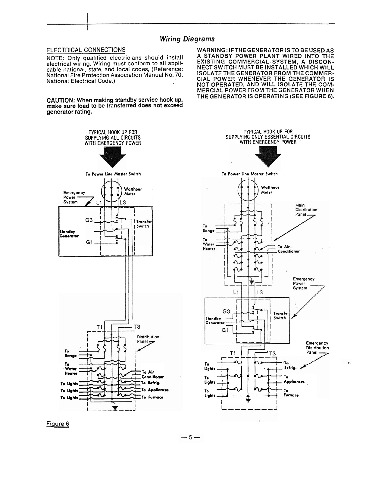
Wiring
Diagrams
ELECTRICAL CONNECTIONS
NOTE: Only qualified electricians should .install
electrical wiring. Wiring must conform to all applicable national, state, and local codes, (Reference:
National Fire Protection Association Manual No.
70,
National Electrical Code.)
WARNING: IFTHEGENERATOR ISTO BEUSEDAS
A STANDBY POWER PLANT WIRED INTO THE
EXISTING COMMERCIAL. SYSTEM, A
DISCON-
NECTSWITCH MUST BE INSTALLED WHICH WlLL
ISOLATE THE GENERATOR FROM THE COMMERCIAL POWER WHENEVER THE GENERATOR IS
NOT OPERATED, AND WlLL ISOLATE THE COMMERCIAL POWER FROM THE GENERATOR WHEN
CAUTION:
When making standby service hook up,
THE GENERATOR IS OPERATING (SEE FIGURE
6).
make sure load to be transferred does not exceed
generator rating.
TYPICAL HOOK UP FOR
SUPPLYING ALL CIRCUITS
WlTH EMERGENCY POWER
TYPICAL HOOK UP FOR
SUPPLYING ONLY ESSENTIAL CIRCUITS
WlTH EMERGENCY POWER
To Power Line Master Switch
Wanhour
,
Emergency
Power
System
L1 L3
I-
--'-
--
1
Studby
Ci.nerolor
I
I
L-----
-J
Te
.
Watw
ktu
To
Air
bnditioner
Te
Ughh
To Refn'g.
1-
Ughk
To Applianc
1e
Ughk
To Fumace
To
Powor Line Morter Switch
Watthour
Meter
Emergency
Distribution
T
1
~3
Panel
I--
-'-------
To
a
Lights
-+
,
,
To
'
'
'1
TO
Lights
+,
4
+
Appliancer
-
To
-i--
"t.
To
Lbhts
=
.L
A
f
Furnace
I
7
1
Figure
6
-
Page 6

Maintenance
GENERAL
Routine preventive maintenance minimizes costly
repairs and generator down-time. Before each use,
inspect the generator: gear case oil level should be
correct. cooling vents and screens should be clear,
and generator mounting hardware should be tight.
Clean and inspect the generator after storing it for
long periods, and after using it in extremely dusty
conditions or in severe weather, such as rain or
blowing snow.
CAUTION: The manufacturer strongly recornmends running the generator under load at least
once a month in order to evaporate any accumulated moisture condensation.
LUBRICATION
The generator bearings are factory lubricated and
sealed, and require no further lubrication.
Splined generator input shaft should be cleaned and
lubricated with a thin
iiim of grease before and after
each use of the generator.
Coupling shaft (tumbling ,bar) requires greasing.
Keep the universal joints in the coupling shaft free
from grease and dirt buildup.
CAUTION: Do not overlubricate the universal
joints.
,--
40
hrs.
. . . . . . .
-8
hrs.
LA
Figure
7
--
Lubrication for Typical
Tumbling Bar (Coupling
Shaft)
See
Figure 7 for recommended lubrication schedule
for tumbling bar.
Check the generator gear case oil level before each
use of the generator. Maintain the oil level at oil level
plug height.
Figure 5 illustrates oil level plug loca-
tion. The generator is shipped with lubricant in the
gear case. Specifications for gear case lubricant
are:
API Service: GL-5
Grade: SAE 85W-90-140
Amount: 1 quart
The following kinds of oil are recommended for use
in the generator gear case: Motil SAE 85W-90-140
API Service GL-5,
SunocoIDX XL80-90-140, Kendal
Three
Star85W-140, Amoco 85W-140. or equivalent.
CAUTION: Do not overfill generator gear case.
Overfilling causes overheating and oil seal failure.
Change the oil at least once every six months.
Change it more often
if
you use the generator in bad
weather.
Use the following procedure to change generator
gear case oil.
(See Figure
5).
1. Remove gear case breather. Soak breather in
cleaning solvent, then allow it to dry.
2. Remove oil level check plug.
3.
Remove the oil drain plug. Drain the oil into a
clean oil resistant container, one quart or more
capacity. Check the oil for metal. Fine metal dust
in the oil does not indicate trouble, but metal
chips do. Dismantle the gear case and look for
damaged gears
if
you find metal chips in the oil.
4. Replace the oil drain plug. Refill the gear case
through the breather port with new oil of the
recommended type. Fill the case up to oil level
check plug height. (It will take about one quart.)
5.
Replace the oil level check plug.
6.
Replace the breather.
CLEANING AND INSPECTING
Use a vacuum cleaner or dry low pressure com-
pressed air (regulated at 25-35 PSI) to clean the
generator periodically.
WARNING: DO NOT CLEAN THE GENERATOR
WHILE IT IS RUNNING.
Proceed as follows:
1. Remove control box cover. Vacuum or blow dust
or debris from the control box. lnspect all wiring
for correct routing, fraying insulation, and secure
connections.
2.
Remove end cover. Vacuum or blow dust and
debris from the inside of the generator. lnspect
wiring for loose connections, fraying insulation
and correct routing.
3.
Replace end cover and control box cover.
GENERATOR STORAGE
Before storing the generator, apply a heavy coat of
grease to the splined input shaft. Store the generator in sheltered area, where it is protected against
snow, rain, and excessive dust.
BRUSHES
Under ordinary circumstances, brushes will operate
for long periods without requiring replacement.
They should be inspected after the first 1000 hours
of operation, and after every 100 hours of operation
thereafter. Remove brushes one at a time and check
for length: be sure that each moves freely in the
brush holder. Brushes should be replaced when
worn down to
318".
Replace brushes in complete
sets. never singly. When replacing brushes. be
careful to reconnect the lead wires properly.
Poor contact (or "skipping") between brush and
slip-ring is caused by oil and grit, on theslip-ring, or
a hard substance in the brush. It can also
becaused
by the brush not being properly seated or contoured
to the slip-ring. To correct this discrepancy, the
brushes can be recontoured by placing 00
sandpaper under the brushes with the abrasive side
to the brushes, and work it back and forth until the
brushes are seated to the slip-rings.
Page 7

Maintenance (Continued)
COLLECTOR RINGSISLIP RINGS
GENERATOR FIELD FOR OPENS AND GROUNDS
.
The continuous copper rings located at the end of
(See Figure 9).
the armature are the collector rings. For proper gen-
1.
Disconnect field leads from rectifier.
erator output, the surface of the collector rings must
2.
Set multimeter to read resistance, and connect
have a highly polished finish. Polish the ring sur-
the meter leads to the field leads. If field is open,
faces occasionally with a crocus cloth to maintain
meterwill read infinite resistance. Replace field if
the finish. it is open.
Testing
ARMATURE FOR OPENS AND GROUNDS
1.
Remove all brushes.
2.
Grounding Test (See Figure 8).
Set multimeter to read resistance. Holding one
meter lead against
a
clean spot on the armature
shaft, touch the other lead to each of the slip
rings (one at a time) while observing the
nleier.
If meter indicates continuity (zero ohms or any
reading lower than infinite resistance), the armature is grounded.
3.
Testing for Opens (See Figure 8).
(Meter still set to read resistance.) Holding one
meter lead on surface of slip ring No.
1.
touch
other meter lead to surface of slip ring No.
2
while
observing the meter. Meter should indicate con-
tinuity (low resistance). If not
(i.e.
if
meter indicates infinite resistance) part of armature windings are open and armature should be replaced.
4.
Check for open between slip rings No.'s2 and 3 in
same manner as you did between rings
1
and
2
(previous paragraph).
FiguJ
TESTING ARMATURE FOR OPENS AND GROUNDS
3.
Connect one meter lead to the field shell (other
lead still connected to one of the field leads).
If
meter indicates continuity (zero ohms or any
reading lower than infinite resistance), the field is
grounded and should be replaced.
F_igu&9 FIELD COIL TESTING
RECTIFIERS (See Figure
10)
The Field Excitation rectifier is a full-wave bridge
rectifier. This type of rectifier has four terminals,
Two AC, a DC positive, and a
DC negative. The recti-
,
fier is tested in the following manner. Connect one
ohmmeter lead to the
pcsitive DC terminal, and the
other lead to
eachof the AC terminals in turn. A high
or low resistance reading will be obtained. Reverse
the meter leads. and an opposite reading should be
observed. Now check from the negative terminal to
each of the AC terminals, using the same procedures as above.
Check each terminal to the case. and no resistance
reading should be observed.
If a battery-powered test light is used, follow the
procedures described above.
If
the rectifier is good.
the light will come on in one direction only.
If the rectifier fails any of the above tests, it should be
considered defective and replaced.
Page 8

Maintenance (Continued)
CONDENSER
..
.
Condensers are built into the generator circuit to
minimize radio interference during operation.
If
a
:
RED
(+)
TEST
LEAD
condenser shorts out, it shorts the generator output.
To determine whether a condenser is shorted, stop
the generator, disconnect the lead wire from the.
brush holder to which the condenser is connected,
start the generator and check the output. If the generator then provides power, the condenser was at
fault and should be replaced.
(If
the generator did
not provide power after the lead wire was disconnected the problem was not caused
by
that con-
denser. Reconnect the lead wire.)
Figure
1
1
-
Wiring-gram Model
Page 9

-
C)
-0
f
E
2
cn
0,
C
.-
L
5
I
z
2
3
0
iil
Page 10

Figure
13
-
Model
Page 11

I
1
Replacement Parts
List
for
Model..CSA8PTOC-31
C
Ref.
No.
Replacement
Parts
List
Description
.
'
Machine screw
Lockwasher
-
5/16 split
Lockwasher
-
1/4 split
Screw
-
1 /4-20 x 5/8
Lockwasher - 1 1 /16 int.
.
Washer - 1/2 flat
Lockwasher
-
1/2 ext.
Nut - 1/2-20 x 3/8
Lockwasher - 1 /2 split
Cap screw
-
1/2-13 x 1
Machine screw
-
#8-32 X 2-1
12
Machine screw
-
#8-32 X 5/16
Cap screw
-
3/8-16 x 1 -3/4
Screw
Cover
Front cover
Upper rear panel only
Lower rear panel (left)
Lower rear panel (right)
Front panel only
Voltmeter
Breaker
-
2 pole 35 amp
Receptacle-250 V
/
50 amp (x-50R)
Circuit
breaker-
1 pole 15 amp
Receptacle
-
120V/
15 amp (5-1 5R)
Saddle
Part No.
Ref.
..
No.
272
40 1
41 1
412
413
414
415
416
417
418
419
420
43 1
432
441A
441 B
442
443
444
447
449
462
463
467
468
469
47 1
49 1
610
Description
Grommet
Fan assembly
End bracket
Oil seal
Bearing
Retainer plate
Gasket
Spacer
Pinion gear
Key
Lockwasher-
1-1/4 int. tooth
Nut, 1-1/4-12
Armature assembly-
less bearings
Bearing
Field coil
Field coil
Pole shoe
Pole shoe retainer
Field shell and brkt
Brush
A.C.
(1 /4x3/8)
Brush
"0"
(1 /4x3/8)
Brush holder A.C.
Capacitor
A.C.
Rectifier
Ground strap -copper
Barrier spacer
Brush plate (bare)
End cover
Base assembly
Qty
.
Fgure
14
-
Gearbox
Ref.
No.
130
134
137
138
140
141
142
144
146
147
118
149
150
151
152
153
154
155
156
157
158
159
-
Qty.
1
1
.1
2
1
4
1
1
1
1
1
2
1
1
1
1
1
1
1
1
1
1
Part No.
55475
46547
20029
54666
46296
1774
46548
200 16
56207
53332
46546
54665
46299
46295
46298
46286
20
133
55476
407 16
20 128
4133
24142
Description
Gear box assembly
Pinion gear (540 rpm)
Seal (input shaft)
Bearing
Shaft (input drive)
Woodruff key
Gear (540 rpm input)
Gasket
-
cover
Backing plate
Safety shield
Gear (driven-540 rpm)
Bearing
Gasket
Retainer
Gasket
Retainer
Snap ring
Gear case
&
cover only
Breather
Shaft
(intermediate driven)
.
.
Roll pin
Street elbow,
90"
Page 12

Egure
15
-
Model
Page 13

I
. .
Replacement
Parts
List
for
Model.
25PTOC-3 / F
Description
Machine screw
Lockwasher
-
5/16 split
Lockwasher
-
1 /4 split
Screw
-
1 /4-20 x 518
Lockwasher - 11 /16 int.
Washer
-
1/2 flat
Lockwasher - 1 /2 ext.
Nut - 1 /2-20 x 318
Lockwasher - 1/2 split
Capscrew-
112-13 x 1
Machine screw
-
#8-32 x 3
Lockwasher
-
#8
Nut - #8-32
Machine screw
-
#8-32 x 5/16
Cap screw
-
7/16 X 1-3/4
Screw
Cover
Fron! cover
Upper rear panel only
Lower rear panel (left)
Lower rear panel (right)
Front panel only
Receptacle
Voltmeter
Breaker
-
2 pole 50 amp
Receptacle-250 V
/
50 amp (x-50R)
Circuit breaker-
1
pole 15 amp
Receptacle-
120V/15 amp (5-15R)
Circuit breaker
-
2 pole rooamp
Main disconnect plug
Receptacle mounting
Ref.
I
1
No. I Part No.
I
Qty.
(
Description
269
1
58805-1
I
1 I Circuit breaker mts plte
I
I
Fan assembly
End bracket
Oil seal
Bearing
Retainer plate
Gasket
Spacer
Pinion gear
Key
Lockwasher-
1-114 int. tooth
Nut, 1-114-12
Armature assernbly-
less bearings
Bearing
Field coil
Field coil
Pole shoe
Pole shoe retainer
Field shell and brkt
Brush A.C.
(3/8x3/8)
Brush
"Q"
(114x3/8)
Brush holder A.C.
Capacitor A.C.
Rectifier
Ground strap -copper
Fiber spacer
Spacer-brush holder
Brush mounting plate
segment (bare)
"0"
ring brush holder
End cover
Base assembly
Replacement
Parts List
Egure
16
-
Gearbox
Ref.
No.
130
134
137
138
140
141
142
144
146
147
148
149
150
151
152
1 53
1 54
155
156
157
158
159
Part No.
55475
46547
20029
54666
46296
1774
46548
200
1
6
56207
53332
46546
54665
46299
46295
46298
46286
20 133
55476
407 16
20128
4133
24 142
Oty.
1
1
1
2
1
4
1
1
1
1
1
2
1
1
1
1
1
1
1
1
1
1
Description
Gear box assembly
Pinion gear (540 rpm)
Seal (input shaft)
Bearing
Shaft (input drive)
Woodruff key
Gear (540 rpm input)
Gasket
-
cover
Backing plate
Safety shield
Gear (driven-540
rpm)
Bearing
Gasket
Retainer
Gasket
Retainer
Snap ring
Gear case
&
cover only
Breather
Shaft
(intermediate driven)
Roll pin
Street elbow.
90"
Page 14

Trouble
Shooting
Chart
GENERAL
compare the clock's second hand movement with
that of the wrist watch. They should run at the same
The
following
lists
various
s~mptoms
of
poor speed.
If
clock
runs
faster, speed
is
too
generator operation with possible causes for them
and the appropriate corrective action. You will need
and
vice
versa).
a volt-ohm meter or test light to check some of the
CAUTION: Most electrical equipment in North
causes. For some of the ocher causes you will need
America operates at frequencies-between
59
and
to check generator speed. To check speed use
a
.
61
Hz
(CPS)..Operating the generator at frequen-
frequency meter, a tachometer, or a
120V-60Hz
elec-
cies outside that range may cause damage to the
tric clock and a correctly operating wrist watch.
generator and/or to electrical equipment driven
by
(Run the electric clock on generator power and
the generator.
SYMPTOM
No output voltage.
.
Low voltage.
High voltage.
Output voltage flickering or fluctuation.
Excessive vibration.
Generator overheating.
Oil leak.
CAUSE(S)
1.
Circuit breaker.
2.
Defective voltmeter.
3.
Short circuit in the load.
4.
-0efective receptacles.
5.
Loose (or broken) wires or connections in the
control box.
6.
Defective rectifier.
7.
Dirty slip rings.
8.
Brushes binding in holders.
9.
Shorted or open armature.
10.-
Shorted or open field coils.
1. Engine speed too slow.
Generator overloaded.
2.
Inadequate engine horsepower.
3.
Incorrect field excitation.
.
4.
Brushes not seated properly, or dirty brushes
and slip rings. (Remove brushes: check for
uneven wear or dirt on brushes or slip rings.)
Engine speed too fast.
1.
Tumbling bar (coupling shaft) misalignment.
2.
Engine speed not constant.
3.
Loose connection in field circuit.
4.
Tumbling bar U-joints not synchronized.
1.
Power take-off misalignment excessive.
2.
Loose mounting nuts and bolts or hold-down
studs.
3.
Universal joints in coupling shaft worn or dry.
4.
Defective bearings.
1.
Poor ventilation.
2.
Generator overloaded.
3.
Shorted turns in field or armature.
1.
Loose plug in gear case.
2.
Defective seal, gasket. or plug in gear case.
7
CORRECTIVE ACTION
1.
Reset circu~t breakers: replace if defective.
2.
Check output with another meter. replace meter
if defective.
3.
Disconnect the load. Check voltage at receptacle.
Check motors, sppliances and load leads lor
short
circu~t. Repa~r short.
4.
Remove panel cover and check for voltage to the
receptacles. Replace defective receptacles.
5.
Remove panel cover and check all wiring and
connections. Tighten
andior repair where neces-
sary.
6. Test rectifier. Replace if defective.
7.
Clean and polish. Use 00 sandpaper and crocus
cloth, never emery paper.
8.
Check brushes for swelling: replace defective
brushes; clean brush holders.
9.
Replace armature if open or shorted.
10. Measure between leads for open or short. Replace coil(s) if defective.
1.
Check engine speed. Increase RPM if necessary.
Reduce load if it is higher than the rated capacity
of the operator (See generator nameplate.)
2.
Generator requires
2.2
H.P.llOOO watts output.
Obtain larger engine if necessary.
3.
Check input AC voltage to rectifier. Check rectifier output OC voltage.
4.
Clean slip rings and seat brushes with sandpaper. (See Maintenance).
Check engine speed for correct input RPM.
1. Reduce tumbling bar misalignment to less than
15 degrees.
2.
Engine governor may be worn or improperly adjusted. Set or repair defective governor.
3.
Check and tighten connections.
4.
Reassemble tumbling bar.
1.
Correct misalignment. It should be less than
15
degrees.
2.
Tighten mounting nuts and bolts: repair holddown stud mountings.
3.
Repair or replace defective parts.
4.
Check for possible causes. Replace defective
bearings.
1.
Clean ventilation and cooling fan screens.
2.
Reduce load. then check voltage and current.
3.
Replace defective components.
1.
Tighten plug.
2.
Replace seal(s), gaskets or plugs. Maintain
correct oil level.
Page 15

*
I
E
F
1
!
,!
2
t
Record
REPLACEMENT COMPONENTS
REQUIRED
I
Service
DATE
MAINTENANCE PERFORMED
I
L
Page 16

Winco warrants that for thirty-six months from date of shipment it will repair or replace
.
....
for the original user the whole or any part of the product found upon examination by Winco
at its factory at
225
South Cordova Avenue, LeCenter, Minnesota, or by any Factory-Authorized Service Station to be defective in material or workmanship under normal standby use
(average less than
50
hours per month) and service.
'
For warranty service, please return the product within one year from date of shipment,
transportation charges prepaid, to the Winco factory or to your nearest Factory-Authorized
Service Station as listed in the 'Yellow Pages' under Generator-Electric.
THERE IS NO OTHER EXPRESS WARRANTY. TO THE EXTENT PERMITTED BY
LA\\', ANY AND ALL IMPLIED WARRANTIES,
INCLUDING THOSE OF
MER-
CHAXTABILITY AND FITNESS FOR A PARTICULAR PUIIPOSE, ARE LIhIITED
TO
THIRTY-SIX MONTHS FROiM DATE OF SHIPMENT, AND LIABILITY FOR IN-
CIDESTALOR COSSEQUENTIAL DAMAGES OR EXPENSES IS EXCLUDED.
Some
states do not allow limitations on the duration of an implied warranty, and some states do
not allow the exclusion or limitation of incidental or consequential damages, so the above
limitation or exclusion may not apply to you. This warranty gives you specific legal rights;
you may have other rights which vary from state to state.
Winco does not warrant trailer tires, tumbling bars, or certain other component parts of
the product since such items are warranted by their manufacturers.
Winco does not warrant alterations or repairs which were made by someone other than the
Winco factory or a Factory-Authorized Service Station and which affect the stability or
reliability of the product.
Winco does not warrant products which have been exposed to misuse and/or negligence or
have been involved in an accident.
Winco reserves the right to change or improve its products without incurring any obliga-
tions to make such changes or improvements on products purchased previously.
!
-@
-'
INCORPPR
ATED
Manulacrurmg-Eng~neerrng 8 Cusromer
Service
225
South
COI~OV~
Avenue
Le Center
MN
56057
(612)
357-6821
 Loading...