

Page 1
Manual Can Opener
Contents / parts list
Included with product
• Can Opener
(with Blade and Gear)
• Can Opener Base
• Installation Kit for
Wood Tables
• Installation Kit for
Stainless Steel Tables
Replacement Parts List
CO-1B: Replacement
Blade Set
CO-1BS: Blade Screw Set
CO-1G: Replacement Gear
CO-1WI: Installation K it for
Wood Tables
CO-1SI: Installation Kit for
Stainless Steel
Tables
USE & CARE MANUAL
CO -1
WARRANTY INFO
Winco warrants these products to be free from defects in
material and workmanship f or a period of one year from the
date of purcha se. The Company’s obligation under this warranty
is limited to repairing or replacing without charge any par t or
parts found to be defec tive under nor mal use. It is the sole
responsibility of the purchaser to re turn the entire unit to the
distributor, transportation charges prepaid.
This warranty does not cover part s that must be replaced under
normal use, including, but not limited to, blades and gears on can
openers. No other warranty, written or verbal, is authorized by the
Company. Warranty information outside the United States may
vary; please consult your distributor.
REPLACEMENT PARTS
Replacement parts are available for purchase. Please check our
website for up to date part s list and prices: www.wincous.com.
CLEANING INSTRUCTIONS
The can opener must be cleaned daily or after each extended use.
Regular maintenance will help prevent unwanted build-up and
harmful bac teria grow th.
1. Use a stainles s cleaning brush to remove all the food and can
opening residue from the gear, the gear cavity, and the knife
blade.
2. Wash the knife, gear, and any splash area on the opener using
warm soapy water. Do not allow componen ts to soak.
3. Thoroughly dr y the knife, gear, and can opener using a dry cloth
or paper towel.
4. Coat the knife and gear with light non-sticking vegetable oil to
prevent rusting when the can opener is not in use.
WINCO
www.wincous.com
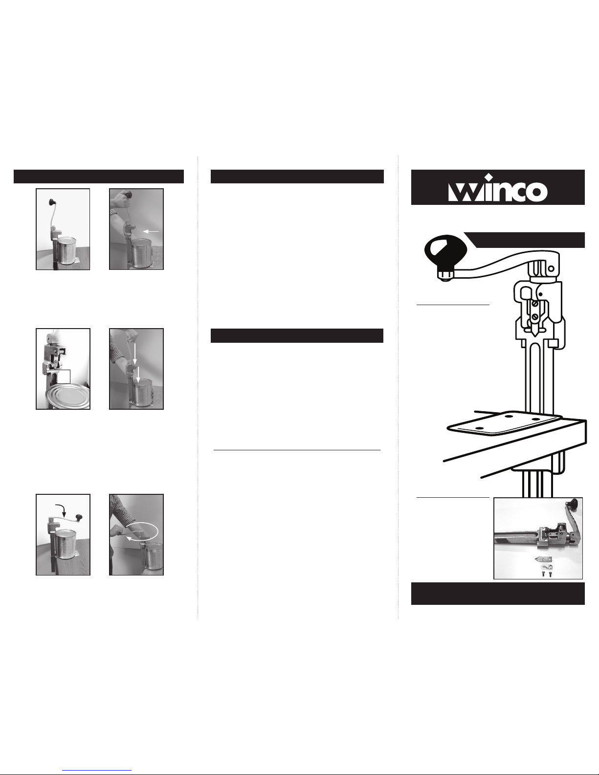
OPERATING INSTRUCTIONS
Figure 1
Figure 3
Figure 6Figure 5
Figure 2
Figure 4
1. Make sure can opener handle is in the unlock position (Figure 1)
and slide it up enough to place a can underneath it on the metal
base. (Figure 2)
2. Hold the can agains t the bar of the opener with a height distance
of 3" between the blade and the top of the can. (Figure 3)
3. Grip the handle firmly and thrus t down onto the c an to puncture
it. (Figur e 4)
4. Lock the handle (Figure 5) and t urn it clock wise. This will
automatically turn the can around. Use your free hand to guide
the can as it rotates. Continue turning the handle until the top of
the can is removed. (Figure 6)
5. Raise the handle to unlock position and lift it up to slide the
opened can out. (Figure 1)
IMPORTANT NOTE: Knife of this opener may be reversed for double
wear but should not be reshaped.
Unock Position
Lock Position
3"
Page 2
MOUNTING INSTRUCTIONS
Mounting can opener on a stainless steel table
Tools required for mounting on a stainless steel table
- 1/8" cobalt or titanium drill bit
- 9/32" cobalt or titanium drill bit
- 7/16 socket, box or open-end wrench
Mounting instructions
1. Place the L-bracket on the stainless steel table in the desired
position where you want to secure the can opener.
2. Mar k the center of each of the three mounting holes of the
L-bracket. These t hree points will be your drilling location.
IM PO RTANT
3. To prevent the drill from slipping out of position, place a
piece of masking tape on each of the three marked points.
Then mark the points again on the masking tape.
4. Drill a small star ter hole on each marked point with a 1/8” cobalt
or titanium drill bit that is specifically used for drilling into
stainless steel.
5. Complete drilling the holes for the screws by using a 9/ 32” cobalt
or titanium drill bit that is specifically used for drilling into
stainless steel.
6. Insert size 1/4 x 20 x 3/4” screws through the L-bracket. Use the
split washer s and nylon lock nut provided.
7. Use a 7/16” socket , bow or open- end wrench to tighten and
secure the screws.
Mounting can opener on a wooden table
(stand ard 2" t hick)
Tools required for mounting on a standard 2” thick wooden table
- 9/32" drill bit
- 7/16 socket, box or open-end wrench
Mounting instructions
1. Place the L-bracket on the stainless steel table in the desired
position where you want to secure the can opener.
2. Mar k the center of each of the three mounting holes of the
L-bracket. These t hree points will be your drilling location.
3. Drill through each point with a 9/ 32” drill bit .
4. Insert size 1/4 x 20 x 2-1/2” screws thr ough the L-bracket. Use
the split washers and nylon lock nut provided.
5. Use a 7/16” socket, bow or open- end wrench to tighten and
secure the screws.
Figure 7
Figure 9
Figu re 11
Figure 8
Figu re 10
Fig ure 12
REPLACEMENT PARTS INSTRUCTIONS
Instructions for replacing gear
1. Stand facing opener on the gear side with the handle lowered.
(Figure 7)
2. Wedge a flat headed screwdriver into the slot on the right side of
the gear to keep it from turning. (Figure 8)
3. Gently turn the handle counter clockwise to unscrew. (Figure 9)
4. Remove used gear and washer.
5. Insert the new gear and washer into the slot. Make sure the
printed side of the gear is facing out. (Figure 10)
6. Position screwdriver on the lef t of the gear. (Figure 11)
7. Turn handle clockwise to screw on. Do not over tighten.
(Figu re 12)
MAIN TENANCE: Keep ge ar and other p arts of opener clean. T he shaft e nd
for the gear must be lubric ated regularly with vegetable oil.
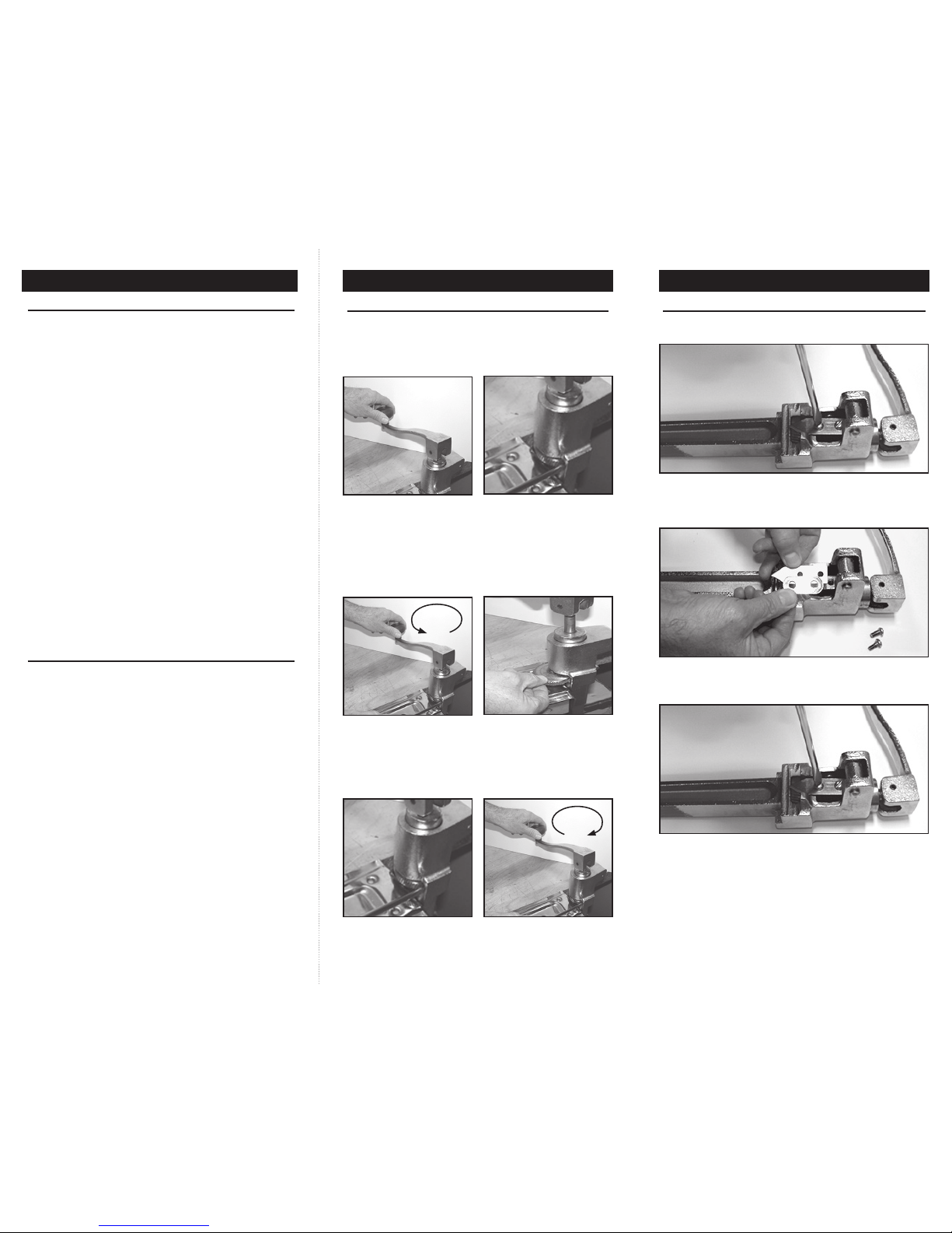
Fig ure 13
Fig ure 15
Fig ure 14
2. Place new knife blade on the holder and then the support plate over the
knife blade. (Figure 14)
REPLACEMENT PARTS INSTRUCTIONS
Instructions for replacing knife blade
1. Make sure handle is raised before removing the two screws holding the
old knife blade. (Figure 13)
3. Align holes and refasten the two screws. (Figure 15)
4. Do not remove or adjust any other parts of the opener.
IMPORTANT NOTE: At the first sign of wear, knife blade must be replaced
with a new factory blade to ensure safe and optimal
operation. Do not attempt to sharpen old knife blade
to reuse.
 Loading...