

Page 1
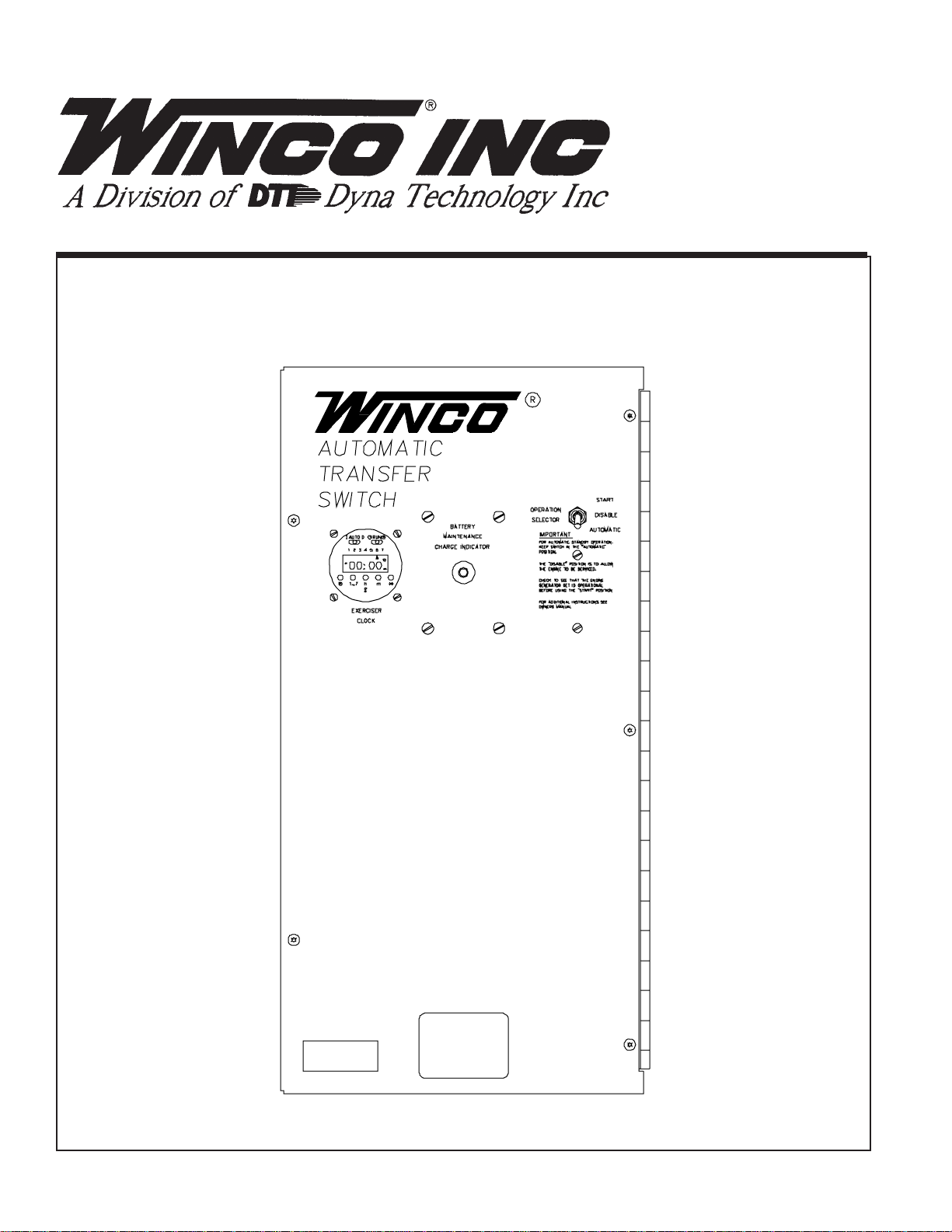
AUTOMATIC
TRANSFER
SWITCH
INSTALLATION AND OPERATORS MANUAL
Page 2

Read and understand all instructions in the
manual before starting and operating the
generator set.
USING THIS MANUAL
Congratulations on your choice of a Winco Automatic
Transfer Switch. You have selected a high-quality,
precision Automatic Transfer Switch designed and
tested to give you years of satisfactory service.
To get the best performance from your new Automatic
Transfer Switch, it is important that you carefully read
and follow the operating instructions in this manual.
Should you experience a problem please follow the
“Things To Check” near the end of this manual. The
warranty listed in this manual describes what you can
expect from WINCO should you need service assistance in the future.
COPY YOUR MODEL AND SERIAL
NUMBER HERE
No other WINCO Automatic Transfer Switch has the
same serial number as yours. It is important that you
record the number and other vital information here. If
you should ever need to contact us on this unit it will
help us to respond to your needs faster.
MODEL____________________________________
SERIAL NUMBER____________________________
PURCHASE DATE____________________________
DEALER___________________________________
TABLE OF CONTENTS
INTRODUCTION i
GUIDE TO PRODUCT SAFETY 1
BASIC INFORMATION 2
Description 2
PREP ARING THE UNIT 3
Unpacking the Unit 3
INST ALLATION PLANNING 3
Installation 3
Automatic Transfer Switch Sizes 3
Installation Notes 3
TRANSFER SWITCH INST ALLATION 4
AC Electrical Connections 4
DC Electrical Connections 5
Exerciser Clock Set Up 5
INITIAL ST ART-UP 6
TROUBLESHOOTING INFORMA TION 6
PREVENTIVE MAINTENANCE 6
WIRING DIAGRAMS
110/60ATS-3/B 7
230/150ATS-3/B 7
400/320ATS-3/B 7
230/150ATS-4/B 7
230/150ATS-17/B 7
ATS-3/A 100/50 8
ATS-3/A 100/100 8
ATS-3/A 225/100 8
ATS-3/A 225/225 8
ATS-3/A 400/300 8
ATS-4/A 100/100 8
ATS-17/A 100/100 8
ATS-4/A 225/100 8
ATS-17/A 225100 8
ATS-4/A 225/225 8
ATS-17/A 225/225 8
ATS-4/A 400/300 8
ATS-17/A 400/300 8
ATS-18/A 100/100 9
ATS-18/A 225/225 9
A.T .S. P ANEL OUTLINE DIMENSIONS 9
12 MONTH W ARRANTY 10
DEALER PHONE # ___________________________
8107-00 60706-131
P AGE i
Page 3

SAFETY INFORMA TION
This engine generator set has been designed and
manufactured to allow safe, reliable performance.
Poor maintenance, improper or careless use can
result in potential deadly hazards; from electrical
shock, exhaust gas asphyxiation, or fire. Please read
all safety instructions carefully before installation or
use. Keep these instructions handy for future
reference. Take special note and follow all warnings
on the unit labels and in the manuals.
b. Keep fuel containers out of reach of children.
c. Do not smoke or use open flame near the
generator set or fuel tank.
d. Keep a fire extinguisher nearby and know its
proper use. Fire extinguishers rated ABC by
NFPA are appropriate.
e. Store fuel only in an approved container, and only
in a well-ventilated area.
f. Follow local codes for closeness to combustible
material.
ANSI SAFETY DEFINITIONS
************************************************************
DANGER:
DANGER indicates an imminently hazardous
situation which, if not avoided, will result in death or
serious injury. This signal word is to be limited to the
most extreme situations.
***********************************************************
************************************************************
WARNING:
WARNING indicates a potentially hazardous situation
which, if not avoided, could result in death or serious
injury.
***********************************************************
***********************************************************
CAUTION:
CAUTION indicates a potentially hazardous situation
which, if not avoided, may result in minor or moderate
injury. It may also be used to alert against unsafe
practices.
************************************************************
NOTE:
CAUTION is also used on the unit labels and in this
manual to indicate a situation that could result in
serious damage or destruction of the equipment and
possible personal injury.
1. ELECTRIC SHOCK - The output voltage present in this
equipment can cause a fatal electric shock. This
equipment must be operated by a responsible
person.
3. DEADL Y EXHAUST GAS - Exhaust fumes from any
gasoline engine contain carbon monoxide, an
invisible, odorless and deadly gas that must be mixed
with fresh air.
a. Operate only in well ventilated areas.
b. Never operate indoors.
c. Never operate the unit in such a way as to allow
exhaust gases to seep back into closed rooms
(i.e. through windows, walls or floors).
4. NOISE HAZARD - Excessive noise is not only tiring,
but continual exposure can lead to loss of hearing.
a. Use hearing protection equipment when working
around this equipment for long periods of time.
b. Keep your neighbors in mind when permanently
installing this equipment.
5. CLEANLINESS - Keep the generator and surrounding
area clean.
a. Remove all grease, ice, snow or materials that
create slippery conditions around the unit.
b. Remove any rags or other material that could
create potential fire hazards.
c. Carefully clean up any gas or oil spills before
starting the unit.
d. Never allow leaves or other flammable material
to build up around the engine intake or exhaust
area.
6. SERVICING EQUIPMENT - All service, including the
installation or replacement of service parts, should be
performed only by a qualified technician.
a. Do not allow anyone to operate the generator
without proper instruction.
b. Guard against electric shock.
c. Avoid contact with live terminals or receptacles.
d. Use extreme care if operating this unit in rain or
snow.
e. Use only three-prong grounded receptacles and
extension cords.
f. Be sure the unit is properly grounded to an
external ground rod driven into the earth.
2. FIRE HAZARD - Natural gas and L.P. present a hazard
of possible explosion and/or fire.
a. Do not refuel when the engine is running or hot.
Allow the engine to cool at least two minutes
before refueling.
PAGE 1
a. Use only factory approved repair parts.
b. Do not work on this equipment when fatigued.
c. Never remove the protective guards, cover, or
receptacle panels while the engine is running.
d. Use extreme caution when working on electrical
components. High output voltages from this
equipment can cause serious injury or death.
e. Always avoid hot mufflers, exhaust manifolds,
an d engine parts. They all can cause severe
burns instantly.
f. Installing a generator set is not a “do-it-yourself”
project. Consult a qualified, licensed electrician
or contractor. The installation must comply with
all national, state, and local codes.
60706-1318107-00
Page 4

TESTING POLICY:
UNPACKING INSTRUCTIONS
Before any Automatic Transfer Switch (A.T.S.) is shipped
from the factory, it is fully checked for performance.
Rated capability of the Automatic Transfer Switch is
based on engineering tests of typical units, and is
subject to, and limited by, the temperature, and other
conditions specified by the manufacturer.
DESCRIPTION
These wall mounted Automatic Transfer Switch (A.T.S.)
are designed for inside installation. The A.T.S. consists
of a line side contactor and a generator side contactor.
The contactors are both electrically and mechanically
interlocked.
An automatic taper battery trickle charger (40 MA max.)
and a seven day electronic exerciser clock are installed
in the A.T.S. as standard equipment. The battery trickle
charger is not designed to recharge a low battery, but is
designed to keep a fully charged battery in peak operating condition. The exerciser clock is electronically
programmable, which allows you to set multiply exercise
periods during the week. These exercise periods can be
from 1 second long to hours long depending on how
long you want it operate.
The A.T.S. also contains the power failure sensing
circuitry necessary to send a start/stop signal to the
engine generator set. These switches are designed to
close to ground (Battery Negative) upon failure of normal
power. If the engine control you are using needs a
positive signal or some other type of signal to initiate the
start sequence you will have to install a pilot relay in the
start circuit. (Consult the factory for details.)
During normal operation the A.T.S. will supply normal line
power to the loads connected to the load terminals in the
switch. Upon an interruption of normal electrical service
the A.T.S. will close the start/stop relay sending a start
signal to the engine-generator set. Once the enginegenerator is producing electricity, the Automatic Transfer
Switch will transfer the connected loads to the enginegenerator set. Upon restoration of normal electrical
service the A.T.S. will sense the return of the normal
commercial power and retransfer the connected loads
back to the normal power source. At the same time the
start/stop relay will open removing the start signal being
sent to the engine control, allowing the engine-generator
set to shut down.
** NOTICE **
When unpacking the Automatic Transfer Switch, be sure
to inspect it carefully for freight loss or damage. If loss or
damage is noted at the time of delivery, require that the
person making the delivery make note of the loss or
damage on the freight bill, or affix his signature under the
consignor’s memo of the loss or damage. Contact the
carrier for claim procedures.
When loss or damage is noted after delivery, segregate
the damaged material, and contact the carrier for claim
procedures. Be sure to retain the packaging material for
carrier inspection.
“Concealed Damage” is understood to mean damage to
the contents of a package which is not evident at the time
of delivery by the carrier, but which is discovered later.
The carrier or carriers are responsible for merchandise
lost or damaged in transit. The title to goods rests with
the consignee when generators are shipped F.O.B.
factory, and only the consignee can legally file a claim.
UNPACKING:
1. Carefully remove the carton.
2. After inspecting the Automatic Transfer Switch for
external physical damage. Carefully inspect the
contactors, contactor interlocks and the contactor
mountings, to insure no damage has occurred to the
contractors during shipment and handling.
3. Check inside the carton for the owner’s manual,
wiring diagram and parts list.
INSTALLATION
General Information
*************
***** WARNING ****
*************
Before proceeding with the installation, be sure the
operation selector switch is in the STOP position.
Before beginning the installation process recheck the
rating of the transfer switch to be certain it can handle the
intended load and is compatible with the entrance
voltage, phase and current ratings. Plans for installation
should be prepared with proper attention to mechanical
and electrical engineering detail to assure a satisfactory
installation. The information in this manual is offered
only as a guide to finalizing your installation plans.
60706-131
PAGE 2
8107-00
Page 5

AUTOMA TIC TRANSFER SWITCH SIZES
CONT ACTOR SIZE
MODEL VOL TAGE PH LINE GEN.
ATS-3/B 100/50 120/240 1 100 AMP 50 AMP
110/60ATS-3/B 120/240 1 1 10 A MP 60 AMP
ATS-3/A 100/100 120/240 1 100 AMP 100 AMP
ATS-4/A 100/100 120/208 3 100 AMP 100 AMP
ATS-17/A 100/100 120/240 3 100 AMP 100 AMP
ATS-18/A 100/100 277/480 3 100 AMP 100 AMP
ATS-3/A 225/100 120/240 1 225 AMP 100 AMP
ATS-4/A 225/100 120/208 3 225AMP 100 AMP
ATS-17/A 225/100 120/240 3 225 AMP 100 AMP
230/150ATS-3/B 120/240 1 230 AMP 150 AMP
230/150ATS-4/B 120/208 3 230 AMP 150 AMP
230/150ATS-17/B 120/240 3 230 AMP 150 AMP
ATS-3/A 225/225 120/240 1 225 AMP 225 AMP
ATS-4/A 225/225 120/208 3 225 AMP 225 AMP
ATS-17/A 225/225 120/240 3 225 AMP 225 AMP
ATS-18/A 225/225 277/480 3 225 AMP 225 AMP
ATS-3A 400/300 120/240 1 400 AMP 300 AMP
ATS-4A 400/300 120/208 3 400 AMP 300 AMP
ATS-17A 400/300 120/240 3 400 AMP 300 AMP
400/320ATS-3/B 120/240 1 400 AMP 320 AMP
Optional A.T.S. sizes are available to meet specific
needs. If you need a switch of a different size contact
WINCO, Inc.
To wire the automatic transfer switch into the existing
wiring, first determine which circuits will be on the
emergency load circuit. If the entire load is to be
transferred, the transfer switch can be wired in directly
after the watt-hour meter or main entrance, provided the
service entrance ampere rating is within the transfer
switch’s rated capability. (See figure 3 and figure 5)
If only specific circuits are to be powered during power
failure conditions, an additional distribution panel
designated “emergency distribution panel” must be
installed. All selected emergency circuits are removed
from main distribution panels and reinstalled in the
emergency distribution panel. Suggested circuits:
freezer, refrigerator, furnace, emergency lights, sump
pump, emergency outlet circuits, etc. Total running load
must not exceed generator rating. (See figure 4)
FIGURE 3
INSTALLA TION NOTES
The load current carrying wires (L) and (T) must be sized
to handle the maximum load current without excessive
voltage drop. By code, the wire must be heavy enough to
handle the full current rating of the main line circuitbreaker (or fuse) in the entrance (or sub-panel) protecting the transfer switch.
All wires should be installed in rigid or flexible conduit.
(Knockouts are provided in the control box)
Because of the many different types of service, feeder,
and distribution equipment, no specific wiring instructions can be provided. It is, however, recommended that
only copper wire be used. In all cases it is essential that
while the load is connected to the generator, there can be
absolutely no feedback from the generator to the power
line or the power line to the generator. When properly
installed, the normal A.T.S. control and safety systems
will eliminate all paths for feedback. Check with your
local electrical inspector on applicable local, state and
federal codes.
NOTE:
It is an excellent idea to install a disconnect in the
incoming power line wiring directly in front of the A.T.S.
panel. This will allow you to test the generator under
load. Should you ever have to work on the switch, you
will be able to disconnect the power and work on the
switch cold, without having the power company pull your
meter.
FIGURE 4
PAGE 3
60706-1318107-00
Page 6

FIGURE 5
INSTALLING THE AUTOMATIC
TRANSFER SWITCH (A.T.S.)
GENERAL INFORMATION
*************
***** WARNING *****
*************
EQUIPMENT DAMAGE- Protect the switch from construction grit and metal chips to prevent a malfunction or
shortened life of the switch.
The Automatic Transfer Switch connects the load (lights,
furnace, outlets, etc.) to the normal power line during
standby. When normal power fails, the A.T.S. starts the
engine generator set, disconnects the power line and
then connects the load to the standby generator set.
When normal power is restored, the automatic switch
retransfers the electrical load to the normal service and
stops the engine. The A.T.S. panel should be mounted
as close to the distribution panel as possible.
*************
***** WARNING *****
*************
All wiring must be done by a licensed electrician, and
must conform to the national electrical code and comply
with all state and local codes and regulations. Check
with your electrical inspectors before proceeding!
Before installing the Automatic Transfer Switch you must
first ensure that the line side contractor will be of
sufficient size to handle your complete service. (i.e. the
main line breaker must not be larger than the line side
contactor rating.) If you will not be able to transfer the
complete electrical system it will be necessary to install
a secondary emergency distribution panel.
*************
***** DANGER *****
*************
Be certain the operation selector switch on the front of the
A.T.S. Control is in the “stop” position and the main power
switch “off”. For your own protection, verify these important safety precautions yourself with reliable instruments
before proceeding.
A.C. ELECTRICAL CONNECTIONS
*************
***** WARNING *****
*************
A FUSED DISCONNECT/CIRCUIT BREAKER MUST BE
INSTALLED BETWEEN THE GENERATOR AND THE
A.T.S. P ANEL TO PREVENT OVERLOADING AND
BURNING OUT OF THE GENERATOR. FAILURE TO
PROVIDE A FUSED DISCONNECT OR CIRCUIT
BREAKER, FOR GENERATOR RATING WILL VOID
YOUR WARRANTY IN CASE OF GENERATOR FAILURE.
SINGLE PHASE A.T .S. CONNECTIONS
The generator terminals (power in from the generator) in
the A.T.S are marked “GENERATOR - G1, G-N, G3”. The
“hot” leads G1 and G3 are wired to the generator side
contactor, terminals G1 and G3.
The line terminals (normal power source) in the A.T.S.
are marked “LINE - L1, L-N, L3”. The “hot” leads L1 and
L3 are wired to the line side contactor, terminals L1 and
L3.
The load terminals (power out to loads) in the A.T.S. are
marked “LOAD - T1, T-N, T3”. The “hot” leads T1 and T3
are wired to the load lugs T1 and T3.
All three neutral connections are made to the appropriate
neutral lugs. These lugs have been prewired common
in the A.T.S. A neutral to ground bond has also been
installed in the A.T.S. panel. If your system requires an
isolated neutral this bond, a copper jumper strap, should
be removed. If this jumper strap is removed remember
to properly ground the Automatic Transfer Switch using
the grounding lug provided.
THREE PHASE A.T .S. CONNECTIONS
The standby generator terminals in the A.T.S are marked
“GENERATOR - G1, G2, G3 and G-N”. The “hot” leads G1,
G2 and G3 are wired to the generator side contactor,
terminals G1, G2 and G3.
The line terminals in the A.T.S. are marked “LINE - L1, L2,
L3” and L-N. The “hot” leads L1, L2 and L3 are wired to
the line side contactor, terminals L1, L2 and L3.
The load terminals in the A.T.S. are marked “LOAD - T1,
T2, T3 and T-N”. The “hot” leads T1 and T3 are wired to
the load lugs T1, T2 and T3.
60706-131
PAGE 4
8107-00
Page 7

All three neutral connections are made to the appropriate
neutral lugs. These lugs have been prewired common
in the A.T.S. A neutral to ground bond has also been
installed in the A.T.S. panel. If your system requires an
isolated neutral this bond, a copper jumper strap, should
be removed. If this jumper strap is removed remember
to properly ground the Automatic Transfer Switch using
the grounding lug provided.
THREE PHASE POWER MONITOR
All three phase Automatic Transfer Switches have a three
phase power monitor installed in them to monitor each
phase for low voltage. This three phase monitor is
phase rotation sensitive also, and comes from the factory
set up for A-B-C phase rotation. If you have trouble
getting the A.T.S. to pickup the line power on initial
installation, try switching the A and B phase on the
monitor. Your rotation may be C-B-A. If so, be sure to
match the generator rotation to your current normal
power rotation or your three phase motors will try to turn
backwards.
*************
***** WARNING *****
*************
When installing a Three Phase 240 Volt Delta system be
sure you know which lead is the high voltage leg (208
Volt line to neutral). The Automatic Transfer Switch is set
up for the high voltage lead to be connected at G2, T2
and L2 only.
D.C. ELECTRICAL INTERCONNECTION
*******CAUTION******
Never run the AC and DC wiring in the same conduit.
The start circuitry in these A.T.S. is a ground to operate
system. When the power fails the start/stop relay on the
door closes and connects the start wire to battery
negative. If your Engine-Generator set needs any other
type of signal to operate, you will need to contact the
WINCO, Inc. Service Department at 507-357-6831.
Three control wires are required to be installed between
the A.T.S. panel and the generator control. Depending on
the distance 14 to 16 gauge stranded wire should be
sufficient. These wires will be labeled “Bat +”, “Bat -”,
and “Start”. The “Bat+” lead is not used for starting, its
sole purpose is to connect the battery trickle charge back
to the battery on the unit.
SETTING THE EXERCISER CLOCK
Setting the current time and date.
1. Position the top right hand (RUN) slide switch to the
left position.
2. Push the clock’s “Day Select Button” until the clock
displays a triangle under the number corresponding to
the current day of the week. (Monday is day 1, Sunday is
day 7)
3. Push the “Hour Select Button” until the display
indicates the correct time in hours. Note: In the afternoon
you should push the button until a “P” is displayed
beside the correct hour.
4. Push the “Minute Select Button” until the display
indicates the correct time in minutes.
5. Position the top right hand (RUN) slide switch to the
center position. The correct time and date should now
be displayed.
Setting the Exerciser Program:
1. Position the top right hand (RUN) slide switch to the
right hand position.
2. Position the top left hand (AUTO) slide switch to the
center position.
3. Press the “Program Select Button” until No 1 is
displayed on the clock to the right of the time.
4. Push the “Day Select Button” to select the day you
want the engine generator set to start up and run. Note:
You can get more than one triangle displayed on the
clock. If this happens just keep pressing the button and it
will work back through the cycle and display only one
triangle under whichever day you desire.
5. With the “Hour” and “Minute” buttons select the time
of day you want the engine to start up.
6. Press the “Program Select Button” until No. 2 is
displayed on the clock.
7. Push the “Day Select Button” to select the day you
want the engine to stop. This must be the same day you
selected in step 4 above.
PAGE 5
8. With the “Hour” and “Minute” buttons, select the time
you want the engine to stop. It is recommended you let
the engine run at least 15 minutes during any exercise
period.
9. Position the top right hand (RUN) slide switch to the
center (RUN) position.
60706-1318107-00
Page 8

CLOCK NOTES:
This seven day exerciser clock has seven additional
program cycles available. Always keep in mind the odd
number turns the unit on and the even number shuts the
unit off. (i.e. (3 on, 4 off) (5 on, 6 off) etc.)
This completes your installation and unit testing.
ALWAYS leave the system in automatic mode unless
servicing the unit. For automatic operation, keep both the
generator set and transfer selector switches in the
“AUTOMA TIC” position.
The relay in the clock will not work unless the transfer
switch is installed and powered up. The relay needs
120 volts AC to operate.
If, when you finish programming the clock, you get an
“EEEE” on the display, it stands for error. The most
common error is that the day of operation has not been
properly set at each step or a program has been turned
on and not turned off. (i.e. programs not properly
grouped 1& 2, 3 & 4, 5 & 6, etc.)
On the face of clock is a small button marked “R”, this is
a reset switch. Depressing this switch will remove all
programming in the clock including the time. Use a
small screwdriver or the tip of a pencil to depress this
button. This should be used only as a last resort.
INITIAL START UP
Move the selector switch on the engine generator set to
the “AUTOMATIC” position. Next move the selector
switch on the A.T.S. panel to the “START” position. The
engine generator set should start up. If it fails to start at
this time, check the selector switch on the engine
generator to be sure it is in the “automatic” position.
Also check to be sure the DC interconnection wiring is
correct. When the selector switch on the A.T.S. is moved
to the “DISABLE” position the engine generator set will
shut off. As long as line power is still applied to the
transfer switch during this test period the A.T.S. will not
transfer the load to the generator.
TROUBLESHOOTING HINTS
ATS P ANEL WILL NOT TRANSFER TO
EMERGENCY SUPPL Y (GENERATOR).
1. No AC generator output from generator.
2. Broken or defective mechanical/electrical inter
locks.
3. Defective holding coil in the generator side
contactor.
4. Wiring error between generator set and transfer
switch.
5. Defective Start Stop Relay
ATS PANEL WILL NOT CLOSE WITH
NORMAL POWER APPLIED.
1. Proper normal line power not available at line
terminals in ATS panel.
2. Defective holding coil in line side contactor.
3. Broken or defective mechanical/electrical inter
locks.
4. Defective Start Stop Relay.
5 Defective Phase Failure Monitor. (Three Phase
Units only)
6. Phase Rotation wrong to the Phase Failure
Monitor.
PREVENTIVE MAINTENANCE
Next you need to test the complete system. To accomplish this you will have to fail the incoming line power to
the A.T.S. panel. First move both selector switches to the
automatic position. Then fail the incoming power. All the
loads connected to the A.T.S. should now be dead. The
engine generator set should now start up. As soon as
the engine generator set reaches operating voltage the
generator side contactor will close and the load will be
applied to the engine generator.
Restoring the line power to the transfer switch will cause
the generator side contactor to open. The line side
contactor will close as soon as the generator side
contactor clears the mechanical interlock and closes the
electrical interlock. These interlocks ensure that you get
a clean ‘break before make’ action in the transfer switch.
The restoration of line power also breaks the run signal
to the engine generator set allowing it to shut down.
60706-131
Reasonable care and preventive maintenance will insure
high reliability and a long life for the Automatic Transfer
Switch.
*************
***** WARNING *****
*************
When performing any type of maintenance on this
equipment make sure the selector switch on the A.T.S. is
in the “disable” position. Disconnect normal power and
confirm with a reliable meter that all power has been
disconnected.
Clean and inspect the switch once a year. De-energize
all power sources, both line and engine generator set,
then brush and vacuum away any excessive dust and dirt
accumulation. You can at this time with the contactor deenergized remove the contactor covers and check the
contacts. Make sure the contacts are clean and not
burned or pitted.
PAGE 6
8107-00
Page 9

230/150ATS-4/B
230/150ATS-17/B
110/60ATS-3/B
230/150ATS-3/B
400/320ATS-3/B
PAGE 7
60706-1318107-00
Page 10

ATS-3/A 100/50
A TS-3/A 100/100
A TS-3/A 225/100
A TS-3/A 225/225
A TS-3/A 400/300
60706-131
A TS-4/A 100/100
A TS-17/A 100/100
A TS-4/A 225/100
A TS-17/A 225/100
A TS-4/A 225/225
A TS-17/A 225/225
A TS-4/A 400/300
A TS-17/A 400/300
PAGE 8
8107-00
Page 11

ATS-18/A 100/100
ATS-18/A 225/225
ATS PANEL OUTLINE
DIMENSIONS
A TS SIZE REF A REF B REF C REF D REF E
100/50 ATS 21.00” 8.00” 8.10” 24.25” 12.375”
100/100 ATS 22.88” 14.00” 10.63” 28.25” 18.375”
225/100 ATS 22.88” 14.00” 10.63” 28.25” 18.375”
225/225 ATS 22.88” 14.00” 10.63” 28.25” 18.375”
400/225 ATS 28.00” 16.00” 12.68” 36.00” 23.88”
400/300 ATS 28.00” 16.00” 12.68” 36.00” 23.88”
110/60 A TS 17.00” 8.00” 8.10” 20.00” 12.375”
230/150 ATS 22.90” 14.00” 10.63” 28.00” 18.375”
400/320 ATS 28.00” 16.00” 12.68” 36.00” 23.875”
PAGE 9
60706-1318107-00
Page 12

WINCO, Incorporated warrants to the original purchaser for 12 months that goods manufactured or supplied by it will be free from defects in workmanship and material, provided such goods
are installed, operated and maintained in accordance with Winco written instructions.
WINCO’s sole liability, and Purchaser’s sole remedy for a failure under this warranty, shall be
limited to the repair of the product. At WINCO’s option, material found to be defective in material or
workmanship under normal use and service will be repaired or replaced. For warranty service,
return the product within 12 months from the date of purchase, transportation charges prepaid, to
your nearest WINCO Authorized Service Center or to WINCO, Inc. at Le Center Minnesota.
THERE IS NO OTHER EXPRESS WARRANTY.
To the extent permitted by law, any and all warranties, including those of merchantability and
fitness for a particular purpose, are limited to 12 months from date of purchase. In no event is
WINCO liable for incidental or consequential damages.
Note: Some states do not allow limitation on the duration of implied warranty and some states
do not allow the exclusion or limitation of incidental or consequential damages, so the above
limitations may not apply in every instance. This warranty gives you specific legal rights which may
vary from state to state.
WINCO reserves the right to change or improve its products without incurring any obligations
to make such changes or improvement on products purchased previously.
EXCLUSIONS:
WINCO does not warrant Engines, Batteries, or Other Component Parts that are warranted
by their respective manufacturers.
WINCO does not warrant modifications or alterations which were not made by WINCO, Inc.
WINCO does not warrant products which have been subjected to misuse and/or negligence
or have been involved in an accident.
225 SOUTH CORDOVA A VE
LE CENTER MN 56057
Phone: 507-357-6831
60706-131
PAGE 10
8107-00
 Loading...