

Wilo Star-Z 20/1, Star-Z 25/2, Star-Z 25/2 DM, Star-Z 25/6 Installation And Maintenance Instructions Manual
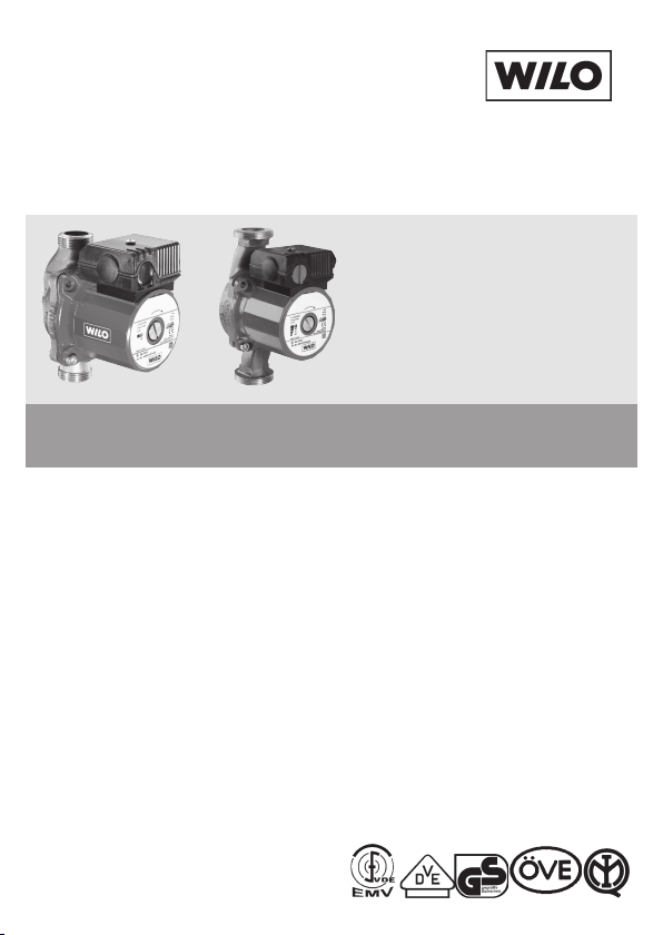
Wilo-Star-Z 20/1, 25/2, 25/2 DM, 25/6
D Einbau- und Betriebsanleitung
GB Installation and Maintenance Instructions
F Notice de mise en service et de montage
I Istruzioni di montaggio, uso e manutenzione
4 069401-Ed.07/2008.04 DDD
E Instrucciones de instalación
y funcionamiento
S Installations- och skötselinstruktioner
CZ Návod k montáži a obsluze
GR Οδηγίες εγκατάστασης και λειτουργίας
3Ù400 V
Fig. 1
Fig. 2
Fig. 4Fig. 3
N
L
N
L
N
L
N
L
/
/
1 230 V
50 H
z
N
L
Fig. 5
Fig. 5 b
Fig. 5 a
Fig. 5 c
Fig. 5

DEUTSCH
D
1. Allgemeines . . . . . . . . . . . . . . . . . 3
2. Sicherheit . . . . . . . . . . . . . . . . . . . 3
3. Transport und
Zwischenlagerung . . . . . . . . . . . . 5
4. Beschreibung von Erzeugnis
und Zubehör . . . . . . . . . . . . . . . . . 5
5. Aufstellung/Einbau . . . . . . . . . . . 5
6. Inbetriebnahme . . . . . . . . . . . . . . 7
7. Wartung . . . . . . . . . . . . . . . . . . . . . 8
8. Störungen, Ursachen
und Beseitigung . . . . . . . . . . . . . . 8
9. Ersatzteile . . . . . . . . . . . . . . . . . . . 8
GB
1. General . . . . . . . . . . . . . . . . . . . . . . 9
2. Safety . . . . . . . . . . . . . . . . . . . . . . . 9
3. Transport and Storage . . . . . . . . 10
4. Description of
Product and Accessories . . . . . . 11
5. Siting/Installation . . . . . . . . . . . . 11
6. Commissioning . . . . . . . . . . . . . . 12
7. Maintenance . . . . . . . . . . . . . . . . . 13
8. Fault finding –
causes and remedies . . . . . . . . . 13
9. Spare parts . . . . . . . . . . . . . . . . . . 14
F
1. Généralité . . . . . . . . . . . . . . . . . . . 15
2. Sécurité . . . . . . . . . . . . . . . . . . . . . 15
3. Transport et stockage
intermédiaire . . . . . . . . . . . . . . . . 16
4. Description du produit
et de ses accessoires . . . . . . . . . 16
5. Installation/montage . . . . . . . . . 17
6. Mise en service . . . . . . . . . . . . . . . 18
7. Entretien . . . . . . . . . . . . . . . . . . . . 19
8. Défauts,
causes et remèdes . . . . . . . . . . . 19
9. Pièces détachées . . . . . . . . . . . . . 19
I
1. Generalità . . . . . . . . . . . . . . . . . . . 20
2. Sicurezza . . . . . . . . . . . . . . . . . . . . 22
3. Trasporto e magazzinaggio . . . 22
4. Descrizione del prodotto
e accessori . . . . . . . . . . . . . . . . . . . 22
5. Montaggio/
Installazione . . . . . . . . . . . . . . . . . 22
6. Messa in esercizio . . . . . . . . . . . . 24
7. Manutenzione . . . . . . . . . . . . . . . 24
8. Blocchi, cause e rimedi . . . . . . . . 24
9. Ricambi . . . . . . . . . . . . . . . . . . . . . 25
1

DEUTSCH
E
1. Generalidades . . . . . . . . . . . . . . . 26
2. Seguridad . . . . . . . . . . . . . . . . . . . 26
3. Transporte
y almacenamiento . . . . . . . . . . . . 28
4. Aplicaciones . . . . . . . . . . . . . . . . . 28
5. Instalación/Montaje . . . . . . . . . . 28
6. Puesta en marcha . . . . . . . . . . . . 30
7. Mantenimiento . . . . . . . . . . . . . . 31
8. Averías, causas y solución . . . . . 31
9. Repuestos . . . . . . . . . . . . . . . . . . . 31
CZ
1. Obecné informace . . . . . . . . . . . . 38
2. Bezpecnostní pokyny . . . . . . . . . 38
3. Preprava a skladování . . . . . . . . . 40
4. Popis výrobku a príslušenství . . 40
5. Instalace/montáž . . . . . . . . . . . . . 40
6. Uvedení do provozu . . . . . . . . . . 42
7. Údržba . . . . . . . . . . . . . . . . . . . . . . 43
8. Poruchy, príciny
a odstranování . . . . . . . . . . . . . . . 43
9. Náhradní díly . . . . . . . . . . . . . . . . 43
2
S
1. Allmän information . . . . . . . . . . . 32
2. Säkerhet . . . . . . . . . . . . . . . . . . . . 32
3. Transport och
lagring . . . . . . . . . . . . . . . . . . . . . . 34
4. Beskrivning av produkten
och tillbehören . . . . . . . . . . . . . . . 34
5. Installation/montering . . . . . . . . 34
6. Drift . . . . . . . . . . . . . . . . . . . . . . . . 36
7. Underhåll . . . . . . . . . . . . . . . . . . . . 36
8. Fel, orsaker och åtgärder . . . . . . 37
9. Reservdelar . . . . . . . . . . . . . . . . . . 37
GR
1. Γενικά . . . . . . . . . . . . . . . . . . . . . . . 44
2. Aσφάλεια . . . . . . . . . . . . . . . . . . . 44
3.
Μεταφορά και προ-σωρινή
αποθήκευση
4. Περιγραφή προϊόν-τος και
εξοπλισµού . . . . . . . . . . . . . . . . . . 46
5. Τοποθέτηση/
Εγκατάσταση . . . . . . . . . . . . . . . . 46
6. Θέση σε λειτουργία . . . . . . . . . . 48
7. Συντήρηση . . . . . . . . . . . . . . . . . . 49
8. Βλάβες, αίτια και
αντιµετώπιση . . . . . . . . . . . . . . . . 49
9. Ανταλλακτικά . . . . . . . . . . . . . . . . 49
. . . . . . . . . . . . . . . . . 46

DEUTSCH
1. Allgemeines
Einbau und Inbetriebnahme nur
durch Fachpersonal
1.1 Verwendungszweck
Die Umwälzpumpen der Baureihe
Star-Z werden zur Förderung von Flüssigkeiten im Trink-/Brauchwasser- und
Lebensmittelbereich eingesetzt.
Die Haupteinsatzgebiete sind:
– Zirkulationssysteme für Trink-/Brauch-
wasser,
– Kühl- und Kaltwasserkreisläufe,
– geschlossene, industrielle Umwälz-
systeme.
1.2 Angaben über die Erzeugnisse
1.2.1 Anschlußund Leistungsdaten
maximal zulässiger
Betriebsdruck: 10 bar
Mindestzulaufdruck am Saugstutzen
bei 50°C: 0,05 bar
bei 95 °C: 0,3 bar
bei 110 °C: 1,0 bar
zulässiger Temperatur-Bereich des
Fördermediums:
Brauchwasser-
systeme
Z 20/1
Z 25/2
Z 25/2 DM
Z 25/6
bis
+ 65 °C
Maximal zulässige
Umgebungstemperatur: 40 °C
Anschlußspannung: siehe Typenschild
Heizungs-
systeme
– 10 °C...
+110°C
aufgenommene Leistung P1:
siehe Typenschild
max. Motordrehzahl: siehe Typenschild
Nennweite der Anschlußrohre (Verschraub.-Pumpe).
Z 20/1: R
Z 25/2: R 1, Ø 28 (G: R 1
Z 25/6: R 1, Ø 28 (G: R1
1
/2, Ø 15 (G: R1)
1
/2)
1
/2)
Zur Vermeidung von Kavitationsgeräuschen ist der Mindest-Zulaufdruck am Saugstutzen der Pumpe
einzuhalten.
2. Sicherheit
Diese Betriebsanleitung enthält grundlegende Hinweise, die bei Aufstellung
und Betrieb zu beachten sind. Daher
ist diese Betriebsanleitung unbedingt
vor Montage und Inbetriebnahme vom
Monteur sowie dem zuständigen Betreiber zu lesen. Es sind nicht nur die
unter diesem Hauptpunkt Sicherheit
aufgeführten allgemeinen Sicherheitshinweise zu beachten, sondern auch
die unter den folgenden Hauptpunkten eingefügten, speziellen Sicherheitshinweise.
2.1 Kennzeichnung von Hinweisen
in der Betriebsanleitung
Die in dieser Betriebsanleitung enthaltenen Sicherheitshinweise, die bei
Nichtbeachtung Gefährdungen für Personen hervorrufen können, sind mit
dem allgemeinen Gefahrensymbol
3
DEUTSCH
bei Warnung vor elektrischer Spannung mit
besonders gekennzeichnet.
Bei Sicherheitshinweisen, deren Nicht-
beachtung Gefahren für die Pumpe/Anlage und deren Funktion hervorrufen können, ist das Wort
ACHTUNG!
eingefügt.
2.2 Personalqualifikation
Das Personal für die Montage muß
die entsprechende Qualifikation für
diese Arbeiten aufweisen.
2.3 Gefahren bei Nichtbeachtung
der Sicherheitshinweise
Die Nichtbeachtung der Sicherheitshinweise kann eine Gefährdung für
Personen und Pumpe/Anlage zur
Folge haben. Die Nichtbeachtung der
Sicherheitshinweise kann zum Verlust jeglicher Schadenersatzansprüche
führen.
Im einzelnen kann Nichtbeachtung
beispielsweise folgende Gefährdungen nach sich ziehen:
– Versagen wichtiger Funktionen der
Pumpe/Anlage,
– Gefährdungen von Personen durch
elektrische und mechanische Einwirkungen.
4
2.4 Sicherheitshinweise für den
Betreiber
Die bestehenden Vorschriften zur Unfallverhütung sind zu beachten.
Gefährdungen durch elektrische Energie sind auszuschließen. Vorschriften
des VDE und der örtlichen Energieversorgungsunternehmen beachten.
2.5 Sicherheitshinweise für
Inspektions- und Montagearbeiten
Der Betreiber hat dafür zu sorgen, daß
alle Inspektions- und Montagearbeiten
von autorisiertem und qualifiziertem
Fachpersonal ausgeführt werden, das
sich durch eingehendes Studium der
Betriebsanleitung ausreichend informiert hat.
Grundsätzlich dürfen Arbeiten an der
Pumpe/Anlage nur im Stillstand durchgeführt werden.
2.6 Eigenmächtiger Umbau und
Ersatzteilherstellung
Veränderungen der Pumpe/Anlage
sind nur nach Absprache mit dem
Hersteller zulässig. Originalersatzteile
und vom Hersteller autorisiertes Zubehör dienen der Sicherheit. Die
Verwendung anderer Teile kann die
Haftung für die daraus entstehenden
Folgen aufheben.
2.7 Unzulässige Betriebsweisen
Die Betriebssicherheit der gelieferten
Pumpe/Anlage ist nur bei bestimmungsmäßiger Verwendung entsprechend Abschnitt 1 der Betriebsan-

DEUTSCH
leitung gewährleistet. Die im Katalog/
Datenblatt angegebenen Grenzwerte
dürfen auf keinen Fall über- bzw.
unterschritten werden.
3. Transport und
Zwischenlagerung
ACHTUNG!
Bei Transport und
Zwischenlagerung ist
die Pumpe gegen Feuchtigkeit und mechanische Beschädigung zu
schützen.
4. Beschreibung
von Erzeugnis und
Zubehör
4.1 Beschreibung der Brauch-
wasserpumpen
Die Umwälzpumpen der Baureihe
Star-Z sind speziell auf die Betriebsverhältnisse in Trink-/BrauchwasserZirkulationssystemen abgestimmt.
Sie sind durch Werkstoffauswahl und
Konstruktion korrosionsfest gegen alle
Bestandteile im Trink-/Brauchwasser.
Drehzahl-Umschaltung: Der Pumpentyp Z 25/6 hat einen Drehknopf am
Klemmenkasten für eine manuelle
Umschaltung in 3 Drehzahlstufen
[1(max) – 2 - 3(min)]. In der Mindeststufe wird die Drehzahl auf etwa
40 ... 50 % der maximalen Drehzahl
reduziert.
Die Stromaufnahme reduziert sich
dabei auf etwa 50 %.
4.2 Lieferumfang
– Pumpe komplett,
– Einbau- und Betriebsanleitung.
4.3 Zubehör
Verfügbares bzw. erforderliches Zubehör muß gesondert bestellt werden.
– Einlegeteile für den Rohranschluß
bei Verschraubungspumpen,
– Zeitschaltgerät SK 601 (nur Direkt-
anschluß von blockierstromfesten
EM-Typen, Anschluß von DM-Typen
nur in Verbindung mit SK 602/ 622
oder Schütz),
– Steckmodul S1R-h, nur für blockier-
stromfeste EM-Typen, nicht für
Z 25/6.
5. Aufstellung/Einbau
5.1 Montage
– Einbau erst nach Abschluß aller
Schweiß- und Lötarbeiten und der
erforderlichen Spülung des Rohrsystems vornehmen. Schmutz kann
die Pumpe funktionsunfähig machen.
– Die Pumpe an gut zugänglicher
Stelle montieren, so daß eine spätere Überprüfung oder ein Austausch leicht möglich ist.
– Wird die Pumpe in ein Trink-/
Brauchwasser-Zirkulationssystem
eingebaut, so muß druckseitig eine
Rückschlagklappe installiert werden.
5
DEUTSCH
– Der Einbau von Absperrarmaturen
vor und hinter der Pumpe ist zu
empfehlen. Damit wird bei einem
evtl. Austausch der Pumpe ein Ablassen und Wiederauffüllen der
Anlage erspart. Die Armaturen sind
so zu montieren, daß Leckwasser
nicht auf den Pumpenmotor oder
Klemmenkasten tropfen kann.
– Spannungsfreie Montage mit waage-
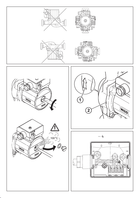
recht liegender Pumpenwelle durchführen. Einbaulagen nach Bild 1
einhalten.
– Der Richtungspfeil auf dem Pumpen-
gehäuse zeigt die Fließrichtung an
(Bild 2, Pos. 1).
ACHTUNG!
ACHTUNG!
– Bei Pumpen, die mit einem Steck-
modul aus- oder nachgerüstet sind,
darf der Luftzugang zum Modul
nicht eingeschränkt werden.
ACHTUNG!
6
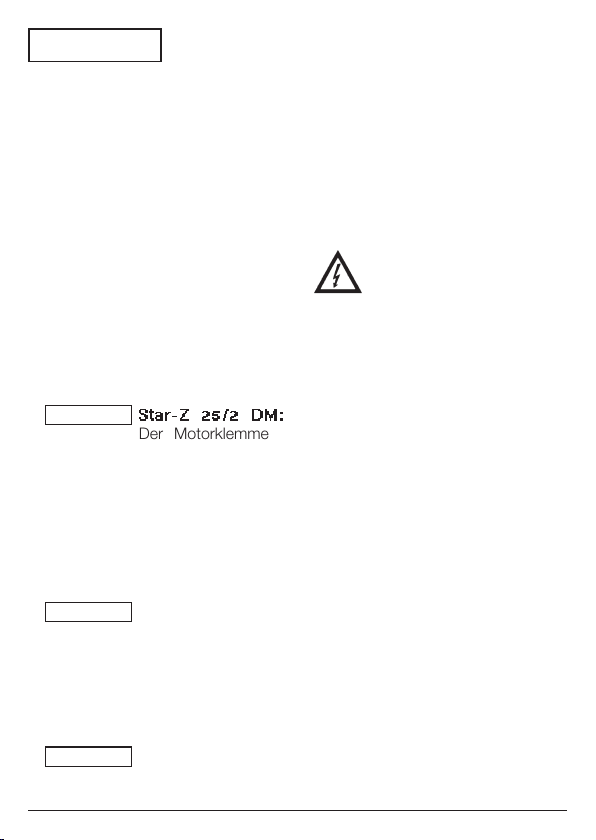
Star-Z 25/2 DM:
Der Motorklemmenkasten darf nicht nach
unten zeigen, da sonst
leicht Wasser eindringen kann. Evtl. muß
das Motorgehäuse
nach Lösen der Inbusschrauben ver
werden.
Die Gehäuse-Flachdichtung nicht beschädigen.
Bei Anlagen, die isoliert werden, darf nur
das Pumpengehäuse
dreh
einisoliert werden. Die
Schwitzwasserlöcher
am Motorflansch müssen offen bleiben
(Bild 2, Pos. 2).
5.2 Elektrischer Anschluß
– Der elektrische Anschluß
ist von einem bei örtlichen
EVU zugelassenen Elektroinstallateur und entsprechend den geltenden VDE-
– Der elektrische Anschluß muß nach
– Um den Tropfwasserschutz und die
t
– Bei Einsatz der Pumpen in Anlagen
– Die Anschlußleitung ist so zu ver-
– Stromart und Spannung des
Vorschriften auszuführen.
VDE 0730/Teil 1 über eine feste
Anschlußleitung erfolgen, die mit
einer Steckvorrichtung oder einem
allpoligen Schalter mit mindestens
3 mm Kontaktöffnungsweite versehen ist.
Zugentlastung der Stopfbuchse
sicherzustellen, ist eine Anschlußleitung mit ausreichendem Außendurchmesser zu verwenden (z. B.
H 05 V V-F 3 (4) G 1,5).
mit Wassertemperaturen über
90 °C muß eine entsprechend
wärmebeständige Anschlußleitung
verwendet werden.
legen, daß in keinem Fall die
Rohrleitung und/oder das Pumpenund Motorgehäuse berührt werden.
Netzanschlusses überprüfen,
DEUTSCH
– Typenschilddaten der Pumpe
beachten,
– Netzanschluß entsprechend dem
Schaltbild (Bild 4/5) ausführ
– 4: 3~400 V
– 5: 1~230 V, blockierstromfest,
– Erdung beachten.
, blockierstromfest,
en:
6. Inbetriebnahme
6.1 Füllen und Entlüften
Anlage sachgemäß füllen. Eine Entlüftung des Pumpenrotorraumes erfolgt selbsttätig bereits nach kurzer
Betriebsdauer. Kurzzeitiger Trockenlauf
schadet der Pumpe nicht. Falls
jedoch eine direkte Entlüftung des
Rotorraumes erforderlich sein sollte,
ist wie folgt zu verfahren:
– Pumpe ausschalten,
– Rohrleitung druckseitig schließen,
– Entlüftungsschraube mit passen-
dem Schraubendreher vorsichtig
öffnen (Bild 3),
– Je nach Temperatur des
Fördermediums und Systemdrucks kann beim Öffnen
der Entlüftungsschraube
heißes Fördermedium in
flüssigem oder dampfförmigem Zustand austreten
bzw. unter hohem Druck
herauschießen.
Es besteht Verbrühungs-
!
gefahr
(Nur bei Einsatz in Warmwasser-Heizungsanlagen).
– Elektrische Teile vor austretendem
Wasser schützen,
– Pumpe einschalten,
– Nach 15 … 30 s Entlüftungsschraube
wieder schließen,
– Absperrorgan wieder öffnen.
ACHTUNG!
Die Pumpe kann bei
geöffneter Verschlußschraube in Abhängigkeit von der Höhe
des Betriebsdruckes
blockieren.
– Je nach Betriebszustand
der Pumpe bzw. der
Anlage (Temperatur des
Fördermediums) kann die
gesamte Pumpe sehr heiß
werden.
Es besteht Verbrennungsgefahr bei Berührung der
Pumpe!
(Nur bei Einsatz in Warm-
-Heizungsanlagen).
wasser
6.2 Einstellen
– Drehrichtungskontrolle bei Dreh-
strommotoren:
or Kontrolle der Drehrichtung Ver-
V
schlußschraube auf der Stirnseite
des Motors entfernen. Durch kurz-
zeitiges Einschalten prüfen, ob die
Drehrichtung der Pumpe mit dem
Pfeil auf dem Typenschild überein-
stimmt. Bei falscher Drehrichtung
2 Phasen vertauschen.
7
DEUTSCH
7. Wartung
Vor Wartung- oder Instandsetzungsarbeiten Pumpe
spannungsfrei schalten und
gegen unbefugtes Wiedereinschalten sichern.
8. Störungen, Ursachen
und Beseitigung
8.1 Pumpe läuft bei eingeschalte-
ter Stromzufuhr nicht:
– Elektrische Sicherungen überprüfen,
– Spannung an der Pumpe prüfen
(Typenschilddaten beachten),
– Kondensatorgröße prüfen (Typen-
schilddaten beachten).
– Motor ist blockiert, z.B. durch Ab-
lagerungen.
Abhilfe: Zentrale Verschlußschraube
entfernen und Gängigkeit des
Pumpenrotors durch Drehen des
geschlitzten Wellenendes mit Hilfe
eines Schraubendrehers prüfen bzw.
deblockieren.
Sicherheitsmaßnahmen wie
bei 6.1 beachten!
Bei hohen Wassertemperaturen und Systemdrücken
Absperrarmaturen vor und
hinter der Pumpe schließen.
Pumpe vorher abkühlen
lassen.
8.2 Pumpe macht Geräusche
– Bei Kavitation durch unzureichen-
den Zulaufdruck.
Abhilfe: System-Vordruck innerhalb
des zulässigen Bereiches erhöhen.
Läßt sich die Betriebsstörung nicht
beheben, wenden Sie sich bitte an
en Sanitär- und Heizungsfach-
Ihr
handwerker oder an den WiloKundendienst.
9. Ersatzteile
Bei Ersatzteilbestellungen sind sämtliche Daten des Typenschildes anzugeben.
Technische Änderungen vorbehalten.
8
ENGLISH
1. General
Installation and service by qualified personnel only
1.1 Fields of Application
Series Star-Z circulating pumps are
suitable of handling liquids in the fields
of service/drinking water and foodrelated liquids.
The main fields of application are:
Domestic and drinking water services.
–
– Cooling and chilled water circulating
systems.
Closed industrial circulating systems
–
1.2 Product Information
1.2.1 Technical Data
Maximum working pressure: 10 bar
Minimum inlet pressure at suction port
at 50 °C: 0.05 bar
at 95 °C: 0.3 bar
at 110°C: 1.0 bar
Permissible temperature range of fluid:
Service water
systems
Z 20/1
Z 25/2
Z 25/2 DM
Z 25/6
up to
+ 65 °C
Maximum permissible ambient temperature: 40°C.
Mains supply voltage: refer to name
plate.
Input power P
1: refer to name plate.
Max. motor speed: refer to name plate
Pipe connection size: (screw ended
pump)
Heating
systems
– 10 °C...
+ 110 °C
Z 20/1: R1/2, DN 15 (G: R1)
Z 25/2: R 1, DN 28 (G: R 1
Z 25/6: R 1, DN 28 (G: R1
The minimum inlet pressure at the
pump suction port must be maintained
to avoid cavitation noise.
2. Safety
These instructions contain basic reference to safety aspects which must be
.
strictly adhered to. It is therefore imperative for the Installer and the Operator
to carefully read these instructions
prior to installation and commissioning. Please observe, not only the
safety rules under the main heading
safety considerations, but also those
added and specially marked under
the ensuing headers.
2.1 Safety Symbols contained in
these Instructions
Safety rules contained herein which, if
not complied with, may be harmful to
persons are specially highlighted by
the following danger symbols:
Danger from general causes:
Danger from electrical causes:
1
/2)
1
/2)
9

ENGLISH
Safety references which, if not complied with, may cause damage to the
pump/plant or impair its function are
highlighted by the word:
ATTENTION!
2.2 Trade Qualifications
Only suitably qualified personnel may
work on this equipment.
2.3 Dangers from Non-Observance
of Safety Rules
Non-observance of safety reference
may cause bodily harm to persons or
damage to the plant. Failure to comply
with safety reference could invalidate
warranty and/or damage claims. In
detail, non-compliance may, for example, cause the following dangerous
situations:
– failure of vital plant functions or
damage to pump/plant,
– causing personal injury from electri-
cal and/or mechanical causes.
2.4 Safety Consideration
for the Operator
Local regulations for the prevention of
accidents must be observed.
Danger from electrical energy must be
excluded (conforming to local or general regulations such as IEC, VDE, etc.).
2.5 Safety Considerations for
Inspections and Installation
Work
It is the Operator’s responsibility to
ensure that inspections and installation work are carried out by authorized
10
and qualified personnel only, having
themselves made fully conversant with
these instructions.
Work must principally be carried out
only with the plant switched off and at
complete standstill.
2.6 Arbitrary Alterations and
Spare Parts Procurement
Any alterations to the plant are only
permitted in agreement with the
manufacturers. Original spare parts
and authorized accessories serve
safety and reliability. The use of unauthorized parts could invalidate
any claims for consequential damages.
2.7 Non-Permissible Operating
Conditions
Operational safety of the plant is only
ensured if used in accordance with
Chapter 1 of these instructions. The
limits stated in the catalogue/data
sheets must not be exceeded under
any circumstances.
3. Transport and
Storage
ATTENTION!
The pump must be
protected from moisture and mechanical
damage at all time
during transport and
intermediate storage.

ENGLISH
4. Description of
Product and
Accessories
4.1 Description of Water Service
Pumps
Series Star-Z circulating water service
pumps have been specially designed
for use in conjunction with domestic/drinking water service systems.
They are, by material selection and
design, corrosion proofed against any
residual parts in domestic/drinking
water. Speed setting: Z 25/6 pump is
equipped with a rotary switch in the
terninal box to enable manual;
3-speed control [1(max) - 2 - 3(min)].
At minimum speed the maximum
speed is reduced to approx.
40 ... 50 %.
The power input is reduced to
approximately 50 %.
4.2 Scope of Supply
– Pump, complete.
– Installation and Operating
Instructions.
4.3 Accessories
Accessories available and/or required
on separate order:
– Union for pipe connections,
– timer switch SK 601 (DOL for
non-overloading 1-phase pumps,
3-phase only in conjunction with
contactor boxes SK 602 /622 or
starter/contactors,
– S1R-h plug-in timer module for
1-phase motors only, except
Z 25/6.
5. Siting/Installation
5.1 Installation
– Install pump only after all weld-
ing /soldering on the pipe system is
completed and the pipe system has
been thoroughly flushed out to be
clear of foreign matter and impurities, as these may cause damage
to the pump.
– Mount pump in an easily accessible
position in order to facilitate later inspection and exchange.
– If used to handle domestic /drinking
water a non-return valve must be
provided and installed at the discharge side.
– To avoid draining and re-filling the
whole of the pipe system on exchange of pump it is recommended
to provide and install isolating valves
at suction and discharge ports of the
pump, to be positioned in such a
way to prevent leakage dripping on
the pump motor or its terminal box.
– Pump to be mounted with the shaft
in the horizontal plane in such a way
that it is not stressed by the pipework. Observe mounting positions
as shown in Fig. 1.
11
ENGLISH
– The arrow on the pump housing
indicates direction of flow (Fig. 2,
Pos. 1).
ATTENTION!
ATTENTION!
– Due care must be given that free
ventilation is not restricted to
pumps equipped or refitted with
plug-in modules.
ATTENTION!
Star-Z 25 /2 DM:
The motor terminal
box must not face
downwar
possible moisture
entry. If necessary
rotate pump head
after undoing the
screws holding the
stator housing.
Take care not to
damage the housing gasket.
Thermal insulation
of pump, if applied,
must be restricted
to the pumps housing only. Ensure that
drain holes at the
motor flange remain
fully open (Fig. 2,
Pos. 2).
ds to avoid
5.2 Electrical wiring
– Electrical work to be car-
ried out by qualified and
licensed electricians in
strict conformity to ruling
national conditions and
local regulations.
12
– All wiring and external switchgear to
comply with ruling local regulations
(use of conduits, all-pole switches,
air gaps, etc.) in accordance with
the latest edition of IEE wiring regulations).
– In order to preserve protection against
moisture entry and to ensure a firm
gland grip the mains cable must
,
have a sufficiently large outside diameter (f.e. H 05 V V-F 3 (4) G 1,5).
– Heat-resisting cable must be used in
the pump which is installed in systems
with water temperatures above 90°C.
– Cable leads to be routed in such
a way to avoid any contact with pipe
work and/or pump or stator housings.
– Check available power supply and
voltage.
– Observe pump name plate data
– All wiring to be carried out accor
to wiring diagram (Fig. 4/5):
– 4: 3~400/415 V
2a:non-overloading
– 5: 1~230/240 V,
2b:non-overloading
– Observe locally ruling earthing regu-
lations.
,
6. Commissioning
6.1 System filling and venting
Ensure that the pipe system is
properly filled. The pump vents itself
automatically after a short operational period. Short-term dry-running will
ding
ENGLISH
not harm the pump. If necessary,
the pump can be directly vented in
accordance with the following procedure:
– Switch-off pump,
– close discharge isolating valve,
– Carefully slacken and remove the
central access plug using screwdriver (Fig. 3).
– Depending on liquid tempe-
rature and system pressure,
hot liquid or vapour can be
releases when undoing the
central access plug.
Beware!
Danger of scalding
(Only when used for hot
water heating).
Protect electrical parts from leaking
–
water
,
– switch-on pump again,
– after 15 … 30 secs close access
plug again,
– open isolating valve again.
ATTENTION!
It is possible that the
pump shaft jams with
the access plug open,
depending on system
pressure.
– The pump can become
extremely hot, depending
on the operating state of
pump or pipe system (fluid
temperature).
Beware of scalding when
touching the pump!
(Only when used for hot
water heating)
!
.
6.2 Pre-Start Adjustments
– Direction of rotation check on
3-phase motors:
Remove central access plug at the
non-drive end of the motor
switch on motor and check
whether sense of rotation corresponds to the arrow on the name
plate; if necessary, change any two
phase wires.
. Briefly
7. Maintenance
Prior maintenance or repair
work switch off the pump and
secure against unauthorized
switching.
8. Fault Findings –
Causes and Remedies
8.1 Pump is switched on, but
fails to run:
– Check power supply fuses.
– Check voltage at pump terminals
(refer to name plate data).
– Check capacitor size (refer to name
plate data!).
– Rotor shaft has jammed, e.g. by
incrustations.
Remedy: Remove central access
plug, check free movement of shaft
or free respectively at the slotted
shaft end by means of a screwdriver.
13

ENGLISH
Observe safety procedures
as for 6.1!
At high water temperatures
and system pressures,
close isolating valves at
both pump ports. First,
allow pump to cool down.
8.2 Noise
– Cavitation due to insufficient inlet
pressure.
Remedy: Increase system pressure
within permissible limits.
If the fault cannot be located or
ectified, please contact your
r
nearest Wilo repr
esentative.
9. Spare Parts
State all name plate data when ordering spare parts.
Technical modifications reserved.
14
FRANÇAIS
1. Généralité
Montage et entretien uniquement
par du personnel qualifié
1.1 Applications
Les pompes de circulation de la
gamme Star Z sont conçues pour
véhiculer des liquides dans le domaine
des eaux potables ou sanitaires et
des produits alimentaires.
Domaines d’application:
– système de bouclage pour eau
potable/eaux industrielles.
Circulation d’eau de refroidissement.
1.2 Caractéristiques
1.2.1 Raccordement et puissance
Pression de service maxi admissible:
10 bar
Pression minimum à l’aspiration
à 50 °C: 0,05 bar
à 95 °C: 0,3 bar
à 110 °C: 1,0 bar
Température admissible du fluide:
Eau sanitaire
Z 20/1
Z 25/2
Z 25/2 DM
Z 25/6
jusqu’à
+ 65 °C
Température ambiante maxi admise:
40°C
Tension de raccordement: voir plaque
signalétique
Puissance absorbée: voir plaque signalétique
Vitesse maxi: voir plaque signalétique
Eau de
chauffage
– 10 °C...
+110°C
Section nominale de passage des
tuyauteries (pompe à RU):
1
Z 20/1: R
Z 25/2: R 1, Ø 28 (G: R 1
Z 25/6: R 1, Ø 28 (G: R1
/2, Ø 15 (G: R1)
1
/2)
1
/2)
Pour éviter les bruits de cavitation, il
faut maintenir la pression à l’aspiration de la pompe indiquée dans le
tableau précédent.
2. Sécurité
La présente notice contient les
instructions à respecter lors du montage et de la mise en service. C’est
pourquoi elle devra être lue attentivement par le monteur et l’utilisateur. Il a
lieu d’observer non seulement ce
point principal mais aussi les prescriptions de sécurité spécifiques abordées
dans les points suivants.
2.1 Signalisation des consignes
de la notice
Les prescriptions de sécurité contenues dans cette notice pour mettre en
garde les personnes sont symbolisées
par:
en ce qui concerne l’électricité par:
Pour annoncer des indications de
sécurité dont la non-observation peut
occasionner un danger pour l’installa-
15
 Loading...