

Wilo Star-Z 15 BN5, Star-Z 15 BS5, Star-Z 15 BS7 Installation And Operating Instructions Manual
Installation and operating instructions
Instructions de montage et de mise en service
Instrucciones de instalación y funcionamiento
Wilo-Star-Z 15
4 118 251-Ed.01 / 2007-11 Kothes!


1
Table of contents ............................................................................................... page
1 General ...................................................................................................................................2
2 Safety .....................................................................................................................................2
3 Transport and interim storage ............................................................................................3
4 Intended use (Application) .................................................................................................. 4
5 Product information .............................................................................................................4
6 Description and function .....................................................................................................5
7 Installation and electrical connection ...............................................................................5
8 Commissioning .....................................................................................................................7
9 Maintenance ..........................................................................................................................7
10 Faults, causes and remedies ..............................................................................................8
English
2 Subject to technical alterations! WILO AG 11/2007
Table of contents+
1 General
1.1 About this document
These Installation and Operating Instructions form an integral part of the product.
They must be kept close to the product and in readiness whenever required.
Precise observance of these instructions is a pre-condition for use of the product
for the intended purpose and for its correct operation. These Installation and
Operating Instructions conform to the relevant version of the equipment and the
underlying safety standards valid at the time of going to press.
2Safety
These instructions contain important information which must be followed when
installing and operating the pump. It is therefore imperative that they be read
by both the installer and the operator before the pump is installed or started up.
Both the general safety instructions in the ‘Safety precautions’ section and
those in subsequent sections indicated by danger symbols should be carefully
observed.
2.1 Symbols and signal words used in these operating instructions
Symbols:
NOTE: ...
Signal words:
NOTE: A notice with useful information for the user in relation to the product. It
alerts the user to possible problems.
General safety symbol
Hazards from electrical causes
DANGER!
Imminently hazardous situation.
Will result in death or serious injury if not avoided.
WARNING!
The user can be exposed to (severe) injury. 'Warning' refers that harm to the
user when the user is neglecting the procedure.
CAUTION!
The product is at risk of damage. 'Caution' refers to the product when the
user is neglecting the procedures.

Installation and operating instructions Wilo Star-Z 15 3
English
2.2 Qualified Personnel
The personnel installing the pump must have the appropriate qualification for
this work.
2.3 Risks incurred by failure to comply with the safety precautions
Failure to comply with the safety precautions could result in personal injury or
damage to the pump or installation. Failure to comply with the safety
precautions could also invalidate warranty and/or damage claims.
In particular, failure to comply with these safety precautions could increase the
possibility of the following risks:
• the failure of important parts of the pump or installation
• the failure of required maintenance and repair procedures
• personal injury due to electrical and mechanical causes
• material damage
2.4 Safety precautions for the operator
Existing regulations for the prevention of accidents must be observed. National
Electrical Codes, local codes and regulations must be followed.
2.5 Safety precautions for inspection and installation work
The operator must ensure that all inspection and installation work is carried out
by authorised and qualified specialists who have carefully reviewed these
instructions.
Work on the pump/unit must be carried out only with the pump disconnected
(locked out) from the electrical supply and at complete standstill.
2.6 Improper use
The operational safety of the pump or installation supplied can only be
guaranteed if it is used in accordance with paragraph 4 of the operating
instructions. The limits given in the catalogue or data sheet must under no
circumstances be exceeded.
3 Transport and interim storage
When receiving the material, check that there has been no damage during the
transport. If shipping damage has occurred, take all necessary steps with the
carrier within the allowed time.
CAUTION! Risk of damage to the pump!
Risk of damage through incorrect handling during transport and storage.
• The pump must be protected against humidity, frost and mechanical damage
during transport or interim storage.

English
4 Subject to technical alterations! WILO AG 11/2007
4 Intended use (Application)
The Star-Z 15 is used to circulate potable (drinking) water.
5 Product information
5.1 Model number explanation
To prevent cavitation noise be sure to maintain the minimum inlet pressure.
When ordering replacement pumps be sure to state all the information given on
the pump and motor name plates.
5.3 Scope of delivery
Pump, power cord and installation/operation manual.
5.4 Accessories
• There are no accessories supplied with this pump. Any check or isolation valves
must be obtained seperately.
• A separate clock timer may be purchased from Wilo.
Example: Star-Z 15 BN5, Star-Z 15 BS5, Star-Z 15 BS7
Star-Z Series: Standard drinking water circulating pump
B Bronze pump housing
N5 NPT union with ½ inch connection
S5 Sweat connection with ½ inch internal sweat
S7 Sweat connection with ¾ inch internal sweat
5.2 Technical data Star-Z 15 BN5 Star-Z 15 BS5, BS7
Power supply 1~115 V / 60 Hz 1~115 V / 60 Hz
Motor power P
1
[W] See name plate See name plate
Maximum motor speed
(constant)
3100 rpm 3100 rpm
Installation length
3”1/8 (3.125) 3”1/8 (3.125)
Maximum permissible operating
pressure
145 psi (10 bar) 145 psi (10 bar)
Minimum inlet pressure
2.9 psi (0.2 bar) 2.9 psi (0.2 bar)
Permissible temperature range
of the circulated fluid
68°F (20°C) to 150°F (65°C
)
or intermittent operation
(approx. 2 hrs)
160°F (70°C)
68°F (20°C) to 150°F (65°C)
or intermittent operation
(approx. 2 hrs)
160°F (70°C)
Installation and operating instructions Wilo Star-Z 15 5
English
6Description and function
6.1 Description of the product
The Star-Z 15 circulating pump is specially designed for use in conjunction with
drinking/sanitary water service systems. Thanks to its design and the materials
used in its construction the pump is resistant to corrosion from elements in
drinking/sanitary water. Motor protection is not required as the motors are
impedance protected.
The Star-Z 15 BN5 model is a compact, ready-to-install pump with ½” union
NPT type threading.
The Star-Z 15 BS5 / BS7 model is a compact, ready-to-install pump with sweat
pipe connections.
There are no check or isolation valves integrated into the product.
7 Installation and electrical connection
Installation and electrical connections must be performed in accordance
with local regulations and only by specialist personnel!
WARNING! Risk of personal injury!
Existing regulations for the prevention of accidents must be followed.
WARNING! Risk of Electrical shock!
Exposure to electrical energy must be prevented.
All local electrical and plumbing codes must be complied with during the
installation of this product.
English
6 Subject to technical alterations! WILO AG 11/2007
7.1 Installation
• The pump must be installed in a frost-free/dust-free and well-ventilated
environment and protected from harsh weather conditions.
• Install the pump in an accessible area with suction and discharge isolation shut
off valves to allow repair and/or removal of the pump. To prevent reverse flow it
may be necessary to install a spring loaded check valve on the suction side of
the pump. The pump is to be installed on the domestic hot water return line
between the water heater and the last fixture in the domestic water system,
pumping towards the water heater.
• The pump must be installed free of stresses from the piping system with the
pump shaft in a horizontal position.
• The directional arrow on the pump housing shows the direction of flow.
CAUTION! Risk of damage to the pump!
Dirt can cause pump failure.
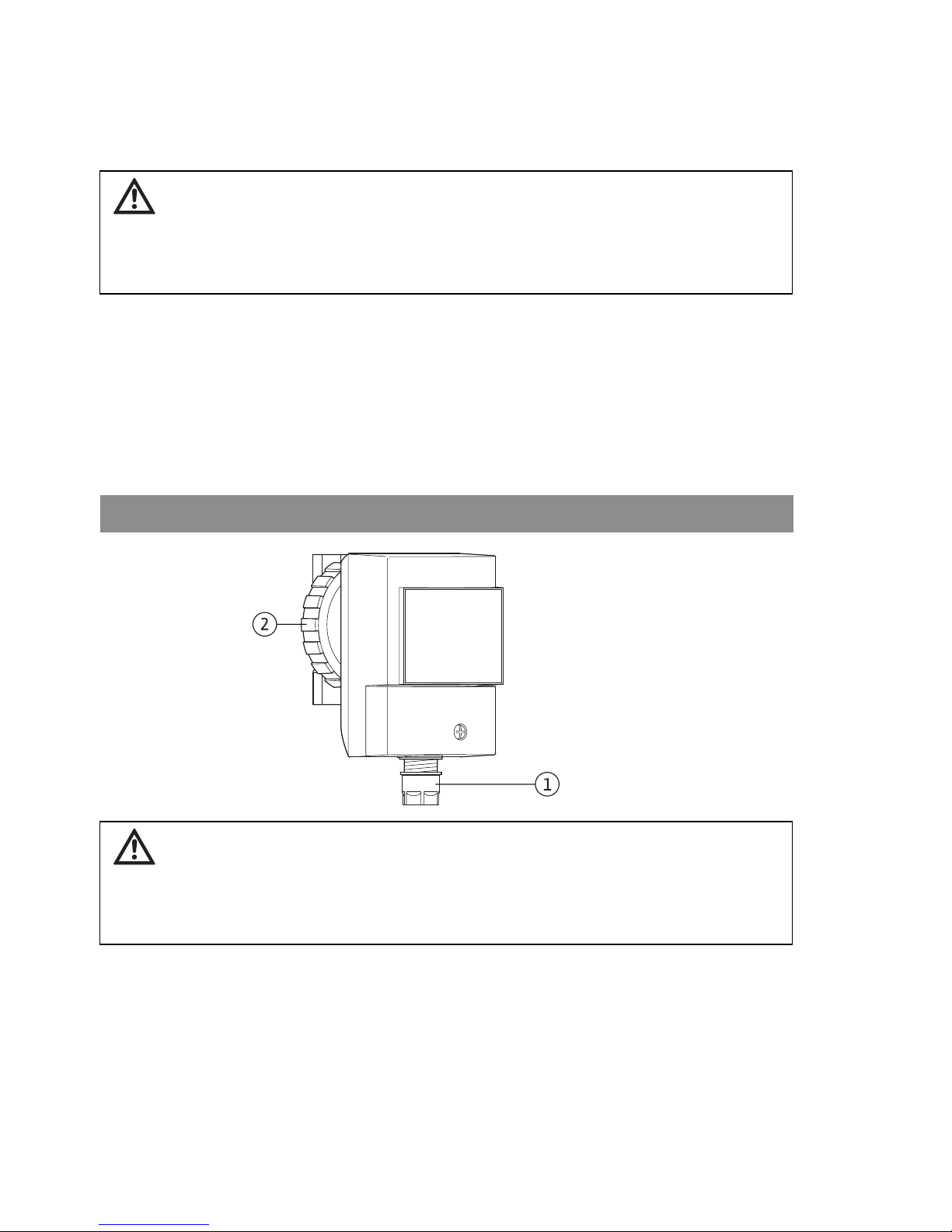
Remove the pump head via the pump union nut (Fig. 1, Item 2) prior to
soldering. Reinstall after soldering the pump body into the piping system has
been completed.
Fig. 1
CAUTION! Risk of damage to the pump!
The screwed cable gland (Fig. 1, Item 1) must face downwards, otherwise
water can penetrate the motor housing. If necessary, rotate the motor
housing after releasing the union nut (Fig. 1, Item 2).
Take care not to damage the housing gasket.

Installation and operating instructions Wilo Star-Z 15 7
English
7.2 Electrical connection
• The pump is delivered together with a three pronged 115 V power cable which
should be plugged into a standard electrical socket.
• The terminal box should not be opened for electrical connection.
8 Commissioning
8.1 Filling and venting
Fill the system correctly. The pump rotor housing is ventilated automatically,
even after short periods of operation. Short periods of dry running does not
damage the pump.
9 Maintenance
Maintenance and repair work should be carried out only by qualified
personnel!
CAUTION! Risk of damage to the pump!
The pump operates at 115 V and must not be connected to a 230 V electrical
supply. This will result in pump failure.
WARNING! Risk of Electrical shock!
Exposure to electrical energy must be prevented.
• When carrying out maintenance and repair work the pump must be switched
off and protected against unauthorised restarting.
• Damage to the connection cable must only be repaired by a qualified
electrician.
WARNING! Risk of scalding!
To prevent scalding prior to disassembling, turn power to the pump off, close
the isolation valves for a period long enough so the pump body does not feel
extremely hot to the touch. This will prevent steam flashing of extremely hot
water.
 Loading...