

Page 1
Wilo-Smart 25/4, 25/6
D Einbau- und Betriebsanleitung
GB Installation and Operating Instructions
F Notice de mise en service at de montage
NL Montage- en bedieningsvoorschriften
E Instrucciones de instalación y funcionamiento
4131018-E d.01 / 2 009-01 -D DD
I Istruzioni di montaggio, uso e manutenzione
P Manual de instalação e funcionamento
GR Οδηγίες εγκατάστασης και λειτουργίας
RUS
Instrukciä po ustanovke i qkspluatacii
Page 2
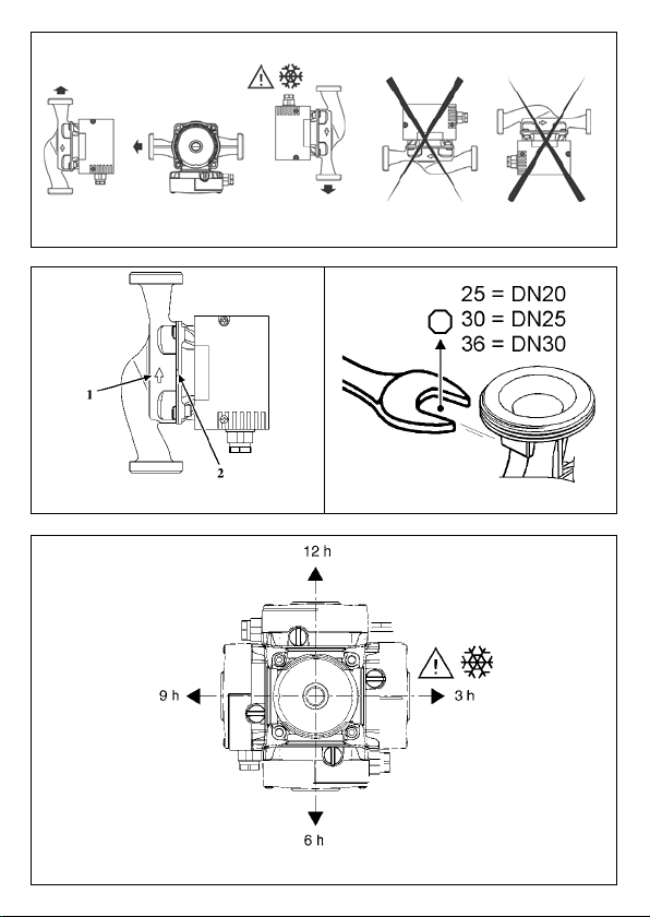
Fig. 1
Fig. 2
Fig. 3
Fig. 4
Page 3
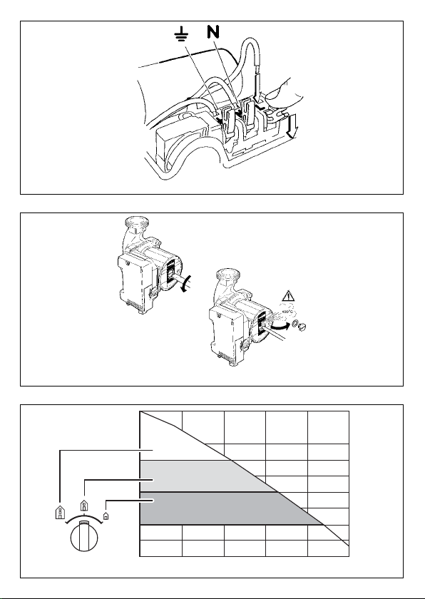
Fig. 5
Fig. 6
H
Fig. 7
Q
Page 4

D Einbau- und Betriebsanleitung 3
GB Installation and Operating Instructions 10
F Notice de mise en service at de montage 17
NL Montage- en bedieningsvoorschriften 24
E Instrucciones de instalación y funcionamiento 31
I Istruzioni di montaggio, uso e manutenzione 38
P Manual de instalação e funcionamento 46
GR Οδηγίες εγκατάστασης και λειτουργίας 53
RUS
Instrukciä po ustanovke i qkspluatacii
62
1
Page 5

Page 6
DEUTSCH
1 Allgemeines
Verwendungszweck
Die Umwälzpumpe Wilo-Smart
dient zur Förderung von
Flüssigkeiten in Rohrsystemen.
Die Pumpe nicht im
Trinkwasser- oder Lebens-
mittelbereich einsetzen.
Die Haupteinsatzgebiete sind:
– Warmwasser-Heizungen, diverse
Systeme,
– Klimageräte und Kaltwasserver-
teilung.
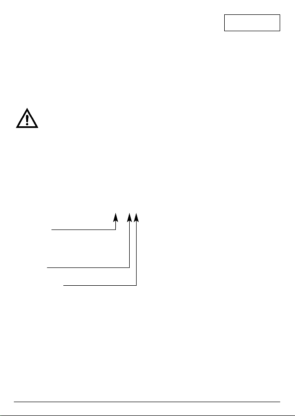
Typenschlüssel Smart 25/4
Heizungsumwälzpumpe,
Nassläufer
Rohrverschraubungspumpe
Nennweite Rohranschluss
[mm] 25 (=1HH),
Maximale Förderhöhe [m]
Anschluß- und Leistungsdaten
Anschlussspannung: 1~230V
±10%, 50Hz
Isolationsklasse: F (155°C)
Temperaturklasse: TF95
Schutzart: IP 42
Differenzdruckbereich: 3 Kanal-
Wahlschalter
Einbaulänge: 180mm
Zul. Betriebsdruck,
max.: 10 bar
Zul. Mediumtemperaturen: +2°C bis
+95°C
Zul. Umgebungstemperatur: maximal: +40°C
Min. Zulaufdruck * am Saugstutzen
bei
+82°C: 0,15 bar
+95°C: 0,3 bar
+110°C: 1,0 bar
* Die Werte gelten bis 300 m über
dem Meeresspiegel; Zuschlag für
höhere Lagen: 0,01 bar/100 m
Höhenzuwachs.
Zur Vermeidung von Kavitationsgeräuschen ist der MindestZulaufdruck am Saugstutzen der
Pumpe einzuhalten!
Fördermedien
– Heizungswasser gem. VDI 2035,
– Wasser und Wasser-/Glykol-
Gemische im Mischungsverhältnis bis 1:1. Durch Beimischungen von Glykol sind die
Förderdaten der Pumpe entsprechend der höheren Viskosität,
abhängig vom prozentualen Mischungsverhältnis zu korrigieren. Nur Markenware mit Korrosionsschutz-Inhibitoren verwenden, Herstellerangaben beachten.
– Bei Verwendung anderer För-
dermedien ist die Freigabe
durch WILO erforderlich.
2 Sicherheit
Diese Betriebsanleitung enthält
grundlegende Hinweise, die bei
3
Page 7
DEUTSCH
Aufstellung und Betrieb zu beachten sind. Daher ist diese Betriebsanleitung unbedingt vor Montage und Inbetriebnahme vom
Monteur sowie dem zuständigen
Betreiber zu lesen.
Es sind nicht nur die unter diesem
Hauptpunkt Sicherheit aufgeführten allgemeinen Sicherheitshinweise zu beachten, sondern auch
die unter den folgenden Hauptpunkten eingefügten, speziellen
Sicherheitshinweise.
Kennzeichnung von Hinweisen
Die in dieser Betriebsanleitung enthaltenen Sicherheitshinweise, die
bei Nichtbeachtung Gefährdungen
für Personen hervorrufen können,
sind mit dem allgemeinen Gefahrensymbol:
und bei Warnung vor elektrischer
Spannung mit:
besonders gekennzeichnet.
Bei Sicherheitshinweisen, deren
Nichtbeachtung Gefahren für die
Pumpe/ Anlage und deren
Funktion hervorrufen können, ist
das Wort:
ACHTUNG!
eingefügt.
4
Personalqualifikation
Das Personal für die Montage
muss die entsprechende Qualifikation für diese Arbeiten aufweisen.
Gefahren bei Nichtbeachtung der
Sicherheitshinweise
Die Nichtbeachtung der Sicherheitshinweise kann eine Gefährdung für Personen und Pumpe/Anlage zur Folge haben. Die
Nichtbeachtung der Sicherheitshinweise kann zum Verlust jeglicher Schadenersatzansprüche führen.
Im einzelnen kann Nichtbeachtung
beispielsweise folgende Gefährdungen nach sich ziehen:
– Versagen wichtiger Funktionen
der Anlage/Pumpe,
– Gefährdungen von Personen
durch elektrische und mechanische Einwirkungen.
Sicherheitshinweise für den
Betreiber
Die bestehenden Vorschriften zur
Unfallverhütung sind zu beachten.
Gefährdungen durch elektrische
Energie sind auszuschließen. Weisungen lokaler oder genereller
Vorschriften [z.B. IEC, VDE usw.]
und der örtlichen Energieversorgungsunternehmen sind zu
beachten.
Page 8

DEUTSCH
Sicherheitshinweise für
Inspektions- und Montagearbeiten
Der Betreiber hat dafür zu sorgen,
dass alle Inspektions- und Montagearbeiten von autorisiertem und
qualifiziertem Fachpersonal ausgeführt werden, das sich durch eingehendes Studium der Betriebsanleitung ausreichend informiert
hat.
Grundsätzlich dürfen Arbeiten an
der Pumpe/Anlage nur im Stillstand durchgeführt werden.
Eigenmächtiger Umbau und
Ersatzteilherstellung
Veränderungen der Pumpe/Anlage
sind nur nach Absprache mit dem
Hersteller zulässig.
Originalersatzteile und vom Hersteller zugelassenes Zubehör dienen der Sicherheit. Die Verwendung anderer Teile kann die
Haftung für die daraus entstehenden Folgen aufheben.
Unzulässige Betriebsweisen
Die Betriebssicherheit der gelieferten Pumpe/Anlage ist nur bei
bestimmungsgemässer Verwendung entsprechend Abschnitt 1
der Betriebsanleitung gewährleistet. Die im Datenblatt angegebenen Grenzwerte dürfen auf keinen
Fall überschritten werden.
3 Transport/
Zwischenlagerung
ACHTUNG!
Die Pumpe enthält
elektronische Bauteile
und ist gegen Feuchtigkeit von außen
sowie mechanische
Beschädigungen
(Stoß / Schlag) zu
schützen.
Die Pumpe darf
Temperaturen außerhalb des Bereiches von -10°C bis
+50°C nicht ausgesetzt werden.
4 Beschreibung Pumpe
Die Pumpe ist mit einem Nassläufermotor ausgestattet. Das Fördermedium schmiert und kühlt die
Gleitlager und den Rotor.
Ein Motorschutz ist nicht erforderlich. Selbst der maximale Überlaststrom kann den Motor nicht schädigen. Der Motor ist blockierstromfest.
Regelungsart: Automatikregelung
Innerhalb des eingestellten Regelkanals liegt der Differenzdruck der
Pumpe.
Die Automatik der Pumpe passt die
Förderhöhe innerhalb des Regelkanals dem Volumenstrom an und
verhindert damit störende Strömungsgeräusche in der Heizungsanlage.
5
Page 9

DEUTSCH
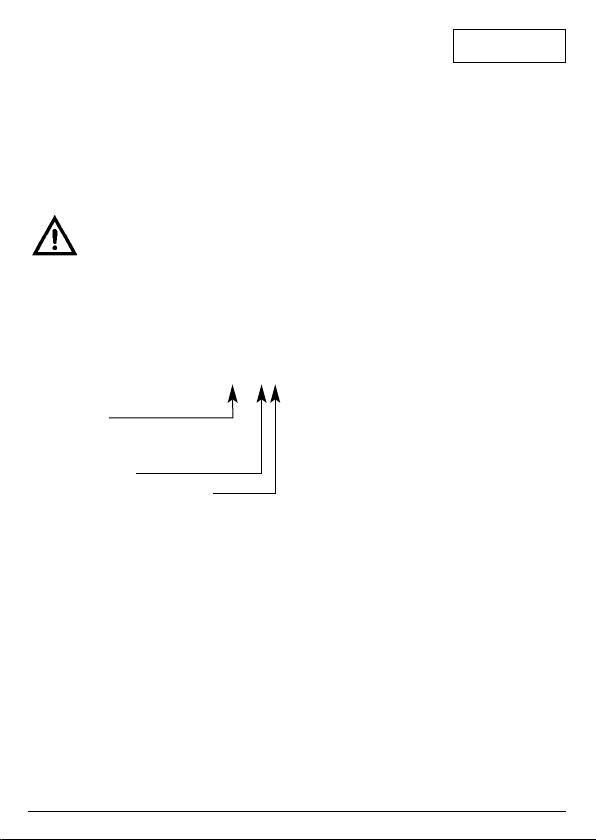
Wahl des Regelkanals
(Differenzdruck Bereiches) (Bild 7)
Um einen effizienten Betrieb der
Heizungsanlage und eine optimale
Anpassung der Pumpe an die
Lastzustände der hydraulischen
Anlage zu gewährleisten, ist es
wichtig den passenden Regelbereich zu wählen. Der Regelkanal
der Pumpe wird mittels eines
3-stufigen Wahlschalters, entsprechend den Anlagenbedürfnissen
ausgewählt. Die Pumpe regelt
innerhalb des gewählten Regelbereiches (Kennfeld) und passt
sich damit einem wechselnden
Leistungsbedarf der Anlage, wie er
besonders beim Einsatz von Thermostatventilen entsteht, ständig an.
5 Aufstellung/Einbau
Montage
ACHTUNG!
– Einbau erst nach Abschluss aller
Schweiß- und Lötarbeiten und
der ggf. erforderlichen Spülung
des Rohrsystems vornehmen.
Schmutz kann die Pumpe funktionsunfähig machen.
ACHTUNG!
Einbau / Inbetriebnahme nur durch
Fachpersonal!
Den Klemmenkasten
während der Montage
der Pumpe geschlossen lassen!.
– Die Pumpe an gut zugänglicher
Stelle montieren, so dass eine
spätere Prüfung oder ein
Austausch leicht möglich ist.
– Der Einbau von Absperr-
armaturen vor und hinter der
Pumpe ist zu empfehlen. Damit
wird bei einem evtl. Austausch
der Pumpe ein Ablassen und
Wiederauffüllen der Anlage erspart. Die Armaturen sind so zu
montieren, dass Leckwasser
nicht auf den Pumpenmotor oder
den Klemmenkasten tropfen
kann.
– Bei Einbau im Vorlauf offener
Anlagen muss der Sicherheitsvorlauf vor der Pumpe abzweigen (DIN EN 12828).
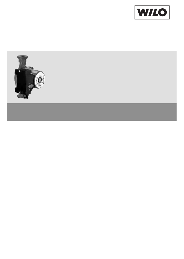
– Spannungsfreie Montage mit
waagerecht liegender Pumpenwelle durchführen. (Einbaulagen
in Bild 1).
– Der Richtungspfeil auf dem
Pumpengehäuse zeigt die Fließrichtung an (Bild 2, Pos. 1).
– Die Pumpe mit einem Maul-
schlüssel gegen Verdrehen
sichern (Bild 3).
– Für eine erforderliche Klemmen-
kastenpositionierung kann das
Motorgehäuse nach Lösen der
Motorbefestigungsschrauben
verdreht werden. Zulässige
Klemmenkastenpositionen nach
Bild 4.
6
Page 10
DEUTSCH
ACHTUNG!
ACHTUNG!
Elektrischer Anschluss
– Der elektrische Anschluß muss
[nach VDE 0730/Teil 1] über eine
feste Anschlussleitung erfolgen,
die mit einer Steckvorrichtung
oder einem allpoligen Schalter
mit mindestens 3 mm Kontaktöffnungsweite versehen ist.
Die Flachdichtung
nicht beschädigen.
Ggf. neue Dichtung
einsetzen:
l86xl 76x2,0mm EP.
Bei Pumpen in Kühlund Kaltwasserkreisläufen ist die Klemmenkastenposition 3h
zu vermeiden!
Bei Anlagen, die isoliert werden, darf nur
das Pumpengehäuse
einisoliert werden.
Der Motor und die
Kondensatablauföffnungen müssen frei
bleiben (Bild 2, Pos.
2)
Der elektrische Anschluss
ist von einem beim örtlichen
Energieversorgungsunterne
hmen (EVU) zugelassenen
Elektroinstallateur entsprechend den geltenden örtlichen Vorschriften (z.B. VDEVorschriften) auszuführen.
– Um den Tropfwasserschutz und
die Zugentlastung der Kabelzuführung sicherzustellen, ist
eine Anschlussleitung mit ausreichendem Außendurchmesser
zu verwenden (z. B. H 05 VV-F 3
G 1,5).
– Die Anschlussleitung ist so zu
verlegen, dass in keinem Fall die
Rohrleitung und/oder das
Pumpen- und Motorgehäuse
berührt werden.
– Stromart und Spannung des
Netzanschlusses müssen den
Angaben auf dem Typenschild
entsprechen.
– Netzanschluss [Phase (L) - Null
(N) - Erde ( )] entsprechend
Bild 5 ausführen.
– Pumpe/Anlage vorschriftsmäßig
erden.
– Nach Anschluss an das elektri-
sche Netz, den Klemmenkasten
wieder verschließen.
6 Inbetriebnahme
Füllen und Entlüften
Eine Entlüftung der Pumpe ist z. B.
dann erforderlich, wenn Heizung
und Pumpe zwar laufen, die
Heizkörper aber dennoch kalt bleiben. Wenn sich im Pumpenraum
Luft befindet, fördert die Pumpe
kein Wasser.
Anlage sachgemäß mit Wasser füllen.
7
Page 11
DEUTSCH
Eine Entlüftung des Pumpenrotorraumes erfolgt selbsttätig
bereits nach kurzer Betriebsdauer.
Kurzzeitiger Trockenlauf schadet
der Pumpe nicht. Falls die Entlüftung des Rotorraumes erforderlich wird, bitte wie folgt verfahren:
– Pumpe ausschalten.
Verbrennungsgefahr bei
Berühren der Pumpe!
Je nach Betriebszustand
der Pumpe bzw. Anlage
(Temperatur des Fördermediums) kann die Pumpe/der Motor sehr heiß
werden.
– Leitung druckseitig schließen.
Verbrühungsgefahr!
Je nach Temperatur des
Fördermediums und des
Systemdrucks kann beim
Öffnen der Entlüftungsschraube heißes Fördermedium in flüssigem oder
dampfförmigem Zustand
austreten bzw. unter hohem
Druck herausschießen.
– Entlüftungsschraube vorsichtig
mit passendem Schraubendreher lösen und ganz herausdrehen (Bild 6).
– Pumpenwelle mit Schrauben-
dreher mehrmals vorsichtig zurückschieben.
– Elektrische Teile vor austreten-
dem Wasser schützen.
– Pumpe einschalten.
ACHTUNG!
– Nach 15...30 s Entlüftungs-
schraube wieder einschrauben.
– Absperrorgan wieder öffnen.
Umschaltung des Regelbereiches
(Differenzdruck-Bereiches)
(Bild 7)
Wenn die Räume nicht ausreichend beheizt werden, kann der
Regelkanal der Pumpe zu niedrig
sein. Dann ist eine Umschaltung
auf einen höheren Regelkanal notwendig.
Ist die Pumpe umgekehrt auf einen
zu hohen Differenzdruck-Bereich
eingestellt, entstehen in den
Leitungen und insbesondere an
gedrosselten Thermostatventilen
Fließgeräusche. Sie sind durch
Umstellung auf einen niedrigeren
Regelkanal zu beheben.
Die Umschaltung erfolgt mit Hilfe
des Wahlschalters am Klemmenkasten.
Nach Umschalten auf einen anderen Regelbereich benötigt die
Heizungsanlage eine gewisse Zeit
bis sich die Regelung stabilisiert.
Die Pumpe kann bei
gelöster Entlüftungsschraube in Abhängigkeit von der Höhe
des Betriebsdruckes
blockieren.
8
Page 12
DEUTSCH
7 Wartung
Vor Wartungs- oder Instandsetzungsarbeiten
Pumpe spannungsfrei
schalten und gegen unbefugtes Wiedereinschalten
sichern.
8 Störungen, Ursachen
und Beseitigung
Pumpe läuft bei eingeschaltetem
Strom nicht:
– Elektrische Sicherungen prüfen,
– Spannung an der Pumpe prüfen
(Typenschild beachten),
– Motor ist blockiert, z.B. durch
Ablagerungen aus dem Heizungswasser.
Bei hohen Wassertemperaturen und Systemdrücken Absperrarmaturen vor
und hinter der Pumpe
schließen. Pumpe vorher
abkühlen lassen.
Wenn sich die Blockierung über
die automatische Deblockierroutine
nicht selbsttätig aufhebt, die
Entlüftungsschraube ganz herausdrehen und Gängigkeit des
Pumpenrotors durch Drehen des
geschlitzten Wellenendes mit Hilfe
eines Schraubendrehers prüfen
bzw. gängig machen (Bild 6).
Pumpe macht Geräusche
– Bei Kavitation durch unzurei-
chenden Zulaufdruck, den
System-Vordruck innerhalb des
zulässigen Bereiches erhöhen.
– Einstellung für den Regelbereich
prüfen, ggf. auf einen niedrigeren umschalten.
Lässt sich die Betriebsstörung
nicht beheben, wenden Sie sich
bitte an den nächstgelegenen
WILO-Kundendienst.
9 Ersatzteile
Bei Ersatzteilbestellungen sind alle
Daten des Typenschildes anzugeben.
Technische Änderungen
vorbehalten!
9
Page 13
ENGLISH
1 General Information
Uses
The Wilo-Smart circulating pumps
are used to pump liquids in pipe
installations.
The pump must not be used
for handling drinking water
or food-related liquids.
Its main fields of application are:
– Hot-water heating, various
systems,
– Air-conditioning units and cold-
water distribution.
Rating plate Smart 25/4
Heating circulating pumps,
wet runner motors
Screwed pipe pump
Nominal width [mm]
25 (=1HH),
Maximum delivery head [m]
Connection and electrical data
Connection voltage: 1~230 V
±10%, 5 0 Hz
Insulation class: F (155°C)
Temperature class: TF95
System of protection: IP 42
Differential pressure
range: 3-channel
selector
switch
Fitting length 180 mm
Perm. operating
pressure, max.: 10 bar
Perm. medium
temperatures: +2°C to
+95°C
10
Perm. ambient
temperature, max.: +40°C
Min. inlet pressure* at suction side
at
+82°C: 0.15 bar
+95°C: 0.3 bar
+110°C: 1.0 bar
*These values are valid up to 300
m above sea level. For higher ele-
vations add: 0.01 bar/100 m.
The minimum inlet pressure must
be maintained in order to avoid
cavitation noise!
Flow media:
– Heating water acc. to VDI 2035
– Water and water/glycol mixtures
in a ratio up to 1:1. In the case of
glycol admixtures the delivery
data of the pump is to be corrected according to the higher
viscosity, depending on the percentage mixture ratio. Only
brand products with anti-corrosion inhibitors should be used.
The manufacturer's instructions
must always be strictly adhered
to.
– Clearance must be obtained
from WILO if other media are
used.
2 Safety
These instructions contain important information which must be followed when installing and opera-
Page 14
ENGLISH
ting the pump. These operating
instructions must therefore be read
by the installer and the responsible
operator before assembly and
commissioning.
In addition to the general safety
instructions laid down here in the
Safety section, the special safety
instructions laid down in the following sections are also to be observed.
Safety marks contained in these
instructions
Safety precautions in these operating instructions which, if not followed, could cause personal injury
are indicated by the symbol:
with the following symbol used to
indicate electrical voltage:
The following symbol is used to
indicate that by ignoring the relevant safety instructions, damage
could be caused to the
pump/machinery and its functions:
ATTENTION!
Staff training
The personnel installing the pump
must have the appropriate qualifications for this work.
Risks incurred by failure to comply
with the safety precautions
Failure to comply with the safety
precautions could result in personal injury or damage to the pump
or installation. Failure to comply
with the safety precautions could
also invalidate any claim for damages.
In particular, failure to comply may
lead to problems such as:
– Failure of important pump or
machinery functions,
– Injury resulting from electrical or
mechanical factors.
Safety precautions for the
operator
The existing regulations for the
prevention of accidents must be
followed.
All risks caused by electrical energy must be eliminated. Local or
general regulations [e.g. IEC, VDE,
etc.] and directives from local
energy supply companies are to
be followed.
Safety information for inspection
and assembly
The operator must ensure that all
inspection and installation work is
carried out by authorized and qualified specialists who have carefully
studied these instructions.
Work on a pump or installation
should only be carried out once
the latter has been brought to a
standstill.
11
Page 15

ENGLISH
Unauthorized modification and
manufacture of spare parts
Alterations to the pump or installation may only be carried out with
the manufacturer's consent.
The use of original spare parts and
accessories authorized by the
manufacturer will ensure safety.
The use of any other parts may
invalidate claims invoking the liability of the manufacturer for any
consequences.
Unauthorized operating methods
The operating safety of the pump
or installation supplied can only be
guaranteed if it is used in accordance with paragraph 1 of the
operating instructions. Under no
circumstances should the limit
values given in the data sheet be
exceeded.
3 Transport/Interim
storage
ATTENTION!
12
The pump contains
electronic components and must be
protected against
external moisture
and mechanical damage
(shock/impact).
It should not be
exposed to temperatures outside the
range -10°C to
+50°C.
4 Pump description
The pump is fitted with a wet runner motor. The pumping medium
lubricates and cools the friction
bearing and rotor.
No motor protection is required.
Even the maximum overload current cannot damage the motor. The
motor operates non-overloading.
Control mode: Automatic
The pump differential pressure falls
within the set control channel.
The automatic pump control adapt
the delivery head within the control
channel to the volume flow and as
such prevent any disruptive flow
noises inside the heating installation.
Control channel selection (differential pressure range) (fig. 7)
In order to guarantee efficient operation of the heating installation
and optimum adaptation of the
pump to the load on the hydraulic
installation, it is important to select
the right control range. The pump
control channel is selected using a
3-stage selector switch in accordance with the installation requirements. The pump operates within
the chosen control range (characteristic diagram) and adapts continuously to the fluctuating power
requirements of the installation, in
particular when thermostat valves
are used.
Page 16
ENGLISH
5 Assembly/Installation
Installation
ATTENTION!
– Installation should only take
place once all welding and soldering work has been completed and the pipe network has
been rinsed. Dirt can have an
adverse effect on the functioning
of the pump.
ATTENTION!
– The pump must be installed in
an easily accessible place to
facilitate inspection and replacement.
– We recommend that you fit shut-
off devices in front of and behind
the pump. This will save having
to drain and refill the system if
the pump needs replacing. The
fittings are to be installed so that
any water that escapes cannot
drip onto the pump motor or terminal box.
– When installing flow pipes in
open units, the expansion flow
pipe must branch off before the
pump.
– Carry out off-load installation
with the pump motor lying hori-
Installation and
service by qualified personnel
only!
Keep the terminal
box close during the
hydraulic pump
installation!
zontally. (Installation positions in
fig. 1).
– An arrow on the pump casing
indicates the direction of flow
(fig. 2, pos. 1).
– Secure the pump against twi-
sting using a spanner (fig. 3).
– In order to attain the correct ter-
minal box position the motor
housing can be turned after loosening the motor fastening screws. The admissible terminal
box positions are shown in fig. 4.
ATTENTION!
ATTENTION!
Electrical connection
Do not damage the
gasket - if necessary use a new gasket: l 86 x l 76x 2.0
mm EP.
Avoid terminal box
position 3h for pumps
for cool and cold water
circulation!
For units which are
to be insulated, only
the pump housing
may be insulated.
The motor and the
condensation water
holes must remain
free from all blockages (fig. 2, pos. 2).
All electrical connections
should be completed by a
qualified electrician. Current
national regulations must be
13
Page 17
ENGLISH
observed (e.g. VDE regulations in Germany).
– According to Part 1 of the VDE
0730, the pump must be
connected to the electrical supply by a solid wire equipped with
a plug or an all-pole switch. The
width of the contact gap must be
at least 3 mm.
– To guarantee protection against
dripping water and the strain
relief of the PG screwed joint, a
connecting cable of suitable
external diameter is to be used
(e.g. H 05 VV-F 3 G 1.5).
– The supply cable must be laid in
such a way that it never touches
the pipework and/or the pump
and motor casing.
– Check that the mains current
and voltage comply with the
data on the rating plate.
– Connect to the mains in accor-
dance with fig. 5 [Phase (L) Zero (N) - Earth ( )].
– The pump/installation must be
earthed in compliance with the
applicable regulations.
– After connecting to the electricity
network, lock the terminal box.
6 Operation
Filling and ventilating the unit
The pump may need venting e.g. if
the heating and pump are working
14
but the heating element remains
cold. If there is air in the pump
chamber, the pump will not pump
water.
Carefully fill the unit with water.
The pump rotor chamber will vent
automatically after a short running
period. Brief dry running will not
damage the pump. If it becomes
necessary to vent the pump, please observe the following procedure:
– Switch off the pump.
Risk of burning if the
pump is touched!
Depending on the operating condition of the pump
and/or installation (fluid
temperature) the entire
pump can become very
hot.
– Close the valve on the discharge
side.
Risk of scalding!
Depending on the fluid
temperature and the
system pressure, if the vent
screw is completely loosened hot liquid or gas can
escape or even shoot out
at high pressure.
– Carefully loosen and fully remo-
ve the vent plug using a suitable
screwdriver (fig. 6).
Page 18

ENGLISH
– Carefully push the pump shaft
back several times using a screwdriver.
– Protect all electrical parts
against the water released from
the unit.
– Switch pump back on.
ATTENTION!
– After 15 to 30 s tighten the vent
plug.
– Re-open the shut-off valve.
Switching the control range (differential pressure range) (fig. 7)
If the rooms are not being sufficiently heated, the pump control
channel may be too low. In this
case you will need to switch to a
higher control channel.
If, on the other hand, the pump is
set at too high a differential pressure range, flow noise may occur
in the lines and in particular at
throttled thermostatic valves. This
can be remedied by switching to a
lower control channel.
This is done using the selector
switch on the terminal box.
After switching to a different control range, it will take some time
before the heating installation control becomes stable.
Depending on the
intensity of the operating pressure, the
pump is liable to
block when the
screw plug is open.
7 Maintenance
Prior maintenance or repair
work switch off the pump
and secure against unauthorized switching.
8 Problems, Causes
and Remedies
Motor is switched on but fails to
run:
– Check electrical fuses.
– Check voltage at pump (observe
rating plate data).
– Motor is blocked, e.g. by depo-
sits from the heating water.
At high water temperatures
and system pressure close
the isolating valves in front
of and behind the pump.
Allow pump to cool down
first.
If the blockage has still not cleared
up after the automatic unblocking
procedure, fully remove the vent
plug then check and if necessary
rectify the free running of the pump
rotor by turning the slotted end of
the shaft with a screwdriver (fig. 6).
Noisy pump operation
– In the event of cavitation as a
result of insufficient admission
pressure, increase the system
admission pressure within the
permitted range.
15
Page 19

DEUTSCH
– Check the control range setting
and if necessary lower.
If the fault cannot be rectified,
contact your nearest WILO
Customer Services.
9 Spare parts
All rating plate data is to be specified when ordering spare parts.
Subject to technical alterations!
16
Page 20
FRANÇAIS
1 Généralités
Applications
La pompe de circulation WiloSmart est conçue pour véhiculer
les fluides dans les tuyauteries.
Ne pas utiliser la pompe
pour véhiculer de l'eau
potable ou des produits ali-
mentaires.
Les principales applications sont
les suivantes :
– la circulation d'eau de chauffage
(divers systèmes)
– la climatisation et la circulation
d'eau glacée
Désignation Smart 25/4
Circulateur de chauffage,
rotor noyé
Pompe à raccord à visser
Diamètre nominal de la
tuyauterie [mm]
25 (=1HH),
Hauteur manométrique
maximale [m]
Raccordement et alimentation
Tension d'alimentation : 1~230V
±10%,
50Hz
Classe d'isolation : F (155°C)
Classe de température :TF95
Type de protection : IP 42
Plage de pression
différentielle :
Commutateur sélectif à 3 canaux
Entraxe : 180 mm
Pression maxi
admissible : 10 bars
Températures de
fluides admissibles : de +2°C à
+95°C
Température ambiante
admissible : maximale :
+40°C
Charge minimale à l'aspiration* à
+82°C : 0,15 bar
+95°C : 0,3 bar
+110°C : 1,0 bar
* Données valables pour une
installation située à 300 mètres
au-dessus du niveau de la mer :
0,01 bar par 100 m supplémentaires.
La pression mini à l'aspiration
doit être respectée pour éviter les
risques de cavitation.
Liquides véhiculés :
– eau de chauffage selon VDI
2035
– eau et mélange eau/glycol en
dosage jusqu'à 1:1. En cas d'ajouts de glycol, corrigez les
valeurs de refoulement de la
pompe suivant la viscosité
supérieure, en fonction du dosage en pourcentage. N'utilisez
que des produits de marques
dotés d'inhibiteurs de protection
contre la corrosion ; respectez
les consignes du fabricant.
– En cas d'utilisation sur d'autres
fluides, l'autorisation de WILO
est requise.
17
Page 21
FRANÇAIS
2 Sécurité
La présente notice contient des
instructions primordiales, qui doivent être respectées lors du montage et de la mise en service. C'est
pourquoi elle devra être lue attentivement par le monteur et l'utilisateur et ce, impérativement avant le
montage et la mise en service.
Il y a lieu d'observer non seulement les instructions générales de
ce paragraphe, mais aussi les prescriptions spécifiques abordées
dans les points suivants.
Signalisation des consignes
Les consignes de sécurité contenues dans cette notice qui, en
cas de non-observation, peuvent
représenter un danger pour les
personnes, sont symbolisées par
le symbole suivant :
En cas de danger électrique, le
symbole indiqué est le suivant :
Les consignes de sécurité dont la
non-observation peut représenter
un danger pour l'installation et son
fonctionnement sont indiquées par
le signe :
ATTENTION!
18
Qualification du personnel
Il convient de veiller à la qualification du personnel amené à réaliser
le montage.
Dangers encourus en cas de nonobservation des consignes
La non-observation des consignes
de sécurité peut constituer un danger pour les personnes, la pompe
ou l'installation. Elle peut également entraîner la suspension de
tout recours en garantie.
Plus précisément, les dangers
encourus peuvent être les
suivants :
– défaillance de fonctions impor-
tantes de l'installation ou de la
pompe
– danger pour les personnes en
cas de dysfonctionnement électrique et mécanique de la
machine
Consignes de sécurité pour l'utilisateur
Il convient d'observer les consignes en vue d'exclure tout risque
d'accident.
Il y a également lieu d'exclure tous
dangers liés à l'énergie électrique.
Respectez les instructions de la
norme NFC 15.100 et des normes
européennes.
Conseils de sécurité pour les travaux d'inspection et de montage
L'utilisateur doit faire réaliser ces
travaux par une personne spécia-
Page 22

FRANÇAIS
lisée qualifiée ayant pris connaissance du contenu de la notice.
Les travaux réalisés sur la pompe
ou l'installation ne doivent avoir
lieu que si les appareillages correspondants sont à l'arrêt.
Modification du matériel et utilisation de pièces détachées non
agréées
Toute modification de la pompe ou
de l'installation ne peut être effectuée que moyennant l'autorisation
préalable du fabricant.
L'utilisation de pièces de rechange
d'origine et d'accessoires autorisés par le fabricant garantit la
sécurité. L'utilisation d'autres pièces dégage la société Wilo de
toute responsabilité.
Modes d'utilisation non autorisés
La sécurité de fonctionnement de
la pompe ou de l'installation livrée
n'est garantie que si les prescriptions précisées au § 1 de la notice
d'utilisation sont respectées. Les
valeurs indiquées dans la fiche
technique ne doivent en aucun cas
être dépassées.
3 Transport et stockage
ATTENTION!
La pompe contient
des composants
électroniques et doit
être protégée contre
l'humidité ainsi que
les dommages mé-
caniques provoqués
par des chocs ou
des coups.
La pompe ne doit
pas être exposée à
des températures
dépassant les limites de -10°C à
+50°C.
4 Description de la
pompe
La pompe est pourvue d'un moteur
à rotor noyé. Le fluide véhiculé
lubrifie et refroidit le palier lisse et
le rotor.
Une protection du moteur n'est
pas nécessaire. Même le courant
de surcharge maximal ne peut
endommager le moteur. Le moteur
résiste au courant de blocage.
Type de régulation: Régulation
automatique :
La pression différentielle de la
pompe correspond au canal de
service.
Le dispositif de commande automatique de la pompe adapte la
hauteur manométrique du canal au
débit volumique et évite ainsi les
bruits d'écoulement gênants dans
l'installation de chauffage.
19
Page 23

FRANÇAIS
Sélection du canal de régulation
(plage de la pression différentielle) (figure 7)
Pour garantir un fonctionnement
efficace de l'installation de chauffage et une adaptation optimale de
la pompe aux cas de charge globaux de l'installation hydraulique, il
est important de sélectionner la
bonne plage de régulation (pression). Le canal de régulation de la
pompe est sélectionné au moyen
d'un commutateur sélectif à 3
niveaux en fonction des besoins
de l'installation. La pompe se régule dans la zone sélectionnée (diagramme caractéristique) et s'adapte ainsi constamment à l'évolution
des besoins en énergie de l'installation suivant la façon dont ils se
manifestent, en particulier lorsqu'on y place des robinets thermostatiques.
5 Installation/Montage
Montage
ATTENTION!
– Le montage devra être réalisé
après avoir terminé toutes les
opérations de soudage et de
brasage et, le cas échéant, le
20
L'installation et la
mise en service
devront être réalisées uniquement
par du personnel
qualifié !
nettoyage de la tuyauterie. La
saleté peut entraver le fonctionnement correct de la pompe.
ATTENTION!
– Installez la pompe dans un
endroit facile d'accès pour permettre toute intervention
ultérieure (contrôle/permutation).
– Il est recommandé d'installer
des vannes d'isolement en
amont et en aval de la pompe.
Ceci évitera de vidanger l'installation lors du remplacement de
la pompe. On orientera les vannes de façon à éviter que les fuites d'eau ne tombent sur le
moteur de la pompe ou la boîte
à bornes.
– En cas de montage dans le con-
duit d'aspiration d'installations
ouvertes, le conduit d'aspiration
de sécurité doit dériver avant la
pompe.
– Réalisez le montage sans tensi-
on sur l'arbre de la pompe positionné horizontalement. (positions de montage en figure 1).
– La flèche sur le corps de pompe
indique le sens d'écoulement du
fluide (fig. 2, pos. 1).
Conserver la boîte à
bornes fermée pendant le montage
hydraulique du circulateur !
Page 24
FRANÇAIS
– Protégez la pompe contre les
torsions à l'aide d'une clé plate
(figure 3).
– Pour raccorder la boîte à bor-
nes, il convient de tourner la
carcasse moteur après avoir
dévissé les vis de fixation du
moteur. Positions de la boîte à
bornes admissibles en figure 4
ATTENTION!
ATTENTION!
Raccordement électrique
Veillez à ne pas
endommager le joint
plat. Le cas échéant,
utilisez un nouveau
joint : l86 x l76 x
2,0 mm EP.
Pour les pompes
employées dans les
circuits d'eau de refroidissement et d'eau
froide, il convient d'éviter la position de la
boîte à bornes 3h !
Si l'on isole l'installation, seul le corps
de la pompe doit
être isolé. Le moteur
et les orifices d'écoulement de condensation doivent
rester libres (figure
2, pos. 2)
Les raccordements électriques et les contrôles doivent être effectués par un
électricien agréé et confor-
mément aux normes en
vigueur.
– Le raccordement électrique doit
être réalisé selon la norme NFC
15.100 ou normes européennes
via un câble électrique fixe
pourvu d'un commutateur ou
d'un contacteur multipolaire
avec au moins 3 mm de plage
d'ouverture de contact.
– Pour assurer la protection de
l'installation contre les gouttes
d'eau et le soulagement de traction du guide-câble, utilisez un
câble de raccordement avec un
diamètre extérieur suffisant (p.
ex. H 05 VV-F 3 G 1,5).
– Le câble de raccordement doit
être placé de façon à ne jamais
entrer en contact avec la canalisation principale et/ou le corps
de pompe et la carcasse moteur.
– La nature du courant et la tensi-
on d'alimentation doivent correspondre aux indications figurant
sur la plaque signalétique.
– Réalisez le raccordement au
réseau [phase (L) - neutre (N) terre ( )] conformément à la
figure 5.
– La pompe/l'installation doivent
être mises à la terre conformément aux prescriptions.
– Après avoir effectué le raccorde-
ment au réseau électrique, refermez la boîte à bornes.
21
Page 25

FRANÇAIS
6 Mise en service
Remplissage et dégazage
Il convient de purger la pompe lorsque les radiateurs restent froids
en dépit du bon fonctionnement du
chauffage et de la pompe. En effet,
lorsque le boîtier de la pompe est
rempli d'air, cette dernière ne
refoule pas d'eau.
Remplissez l'installation d'eau.
Normalement, le dégazage du rotor
de la pompe s'effectue automatiquement après une brève période
de fonctionnement. Un bref fonctionnement à sec n'endommage
pas la pompe. Si le dégazage du
rotor s'avère nécessaire, procédez
de la sorte :
– Arrêtez la pompe
Danger de brûlure au
contact de la pompe !
En fonction des conditions
de fonctionnement de la
pompe ou de l'installation
(température du fluide), la
pompe/le moteur peut
devenir extrêmement
chaud.
– Fermez la vanne d'aspiration
Danger de brûlure !
Selon la température du
fluide et la pression du
système, lorsqu'on ouvre la
vis de dégazage, du fluide
22
brûlant peut s'échapper
sous forme liquide ou
gazeuse ou sortir à haute
pression lors de l'ouverture
de la vis de dégazage.
– Dévissez complètement la vis de
dégazage à l'aide d'un tournevis
adapté (fig. 6)
– Repoussez prudemment à plu-
sieurs reprises l'arbre de la
pompe à l'aide d'un tournevis
– Évitez que des fuites de liquide
ne se répandent sur les parties
électriques
– Enclenchez la pompe.
ATTENTION!
– Au bout de 15 à 30 sec., refer-
mez la vis de dégazage
– Ouvrez à nouveau la vanne
d'arrêt.
Commutation de la plage de régulation (plage de la pression différentielle) (figure 7)
Si le canal de régulation de la
pompe n'est pas suffisant, la
température des locaux à chauffer
sera trop faible. Dans ce cas, il est
nécessaire de passer à un canal
de régulation supérieur.
Si la pression dans
l'installation est importante, la pompe
peut se bloquer lorsque la vis de dégazage est ouverte.
Page 26

FRANÇAIS
Si, à l'inverse, la pompe est réglée
sur une plage de pression différentielle trop élevée, des bruits d'écoulement se font entendre dans la
tuyauterie, et en particulier au
niveau des robinets thermostatiques. On résout ce problème en
passant à un canal de régulation
inférieur.
La commutation s'effectue à l'aide
du commutateur sélectif de la boîte
à bornes.
Après avoir changé de plage de
régulation, l'installation de chauffage requiert un certain temps avant
que la régulation ne se stabilise.
7 Entretien
Avant toute intervention ou
arrêt, mettre les pompes
hors tension et s'assurer
contre toute remise en route
intempestive.
8 Pannes, causes et
remèdes
La pompe ne tourne pas (alors
qu'elle est alimentée en courant) :
– Vérifiez les fusibles
– Vérifiez la tension de la pompe
(respectez la plaque signalétique)
– Le moteur est bloqué (par ex. à
cause d'un dépôt de résidus en
suspension)
Si la température de l'eau
et la pression du système
sont élevées, fermez les
vannes d'isolement en
amont et en aval de la
pompe. Laissez d'abord
refroidir la pompe.
Si le blocage persiste malgré le
mécanisme habituel de déblocage
automatique, dévissez complètement la vis de dégazage et débloquez le rotor au moyen d'un tournevis en tournant l'extrémité fendue de l'arbre (figure 6).
La pompe fait du bruit
– En cas de cavitation en due à
une pression insuffisante à l'aspiration, augmentez la pression
d'aspiration du système dans les
limites autorisées.
– Vérifiez le réglage de la plage de
régulation et, le cas échéant,
passez à un niveau inférieur.
S'il n'est pas possible de remédier
au défaut, veuillez faire appel au
S.A.V. WILO le plus proche.
9 Pièces détachées
Lors de toute commande de pièces détachées, il convient de mentionner toutes les données de la
plaque signalétique.
Sous réserve de modifications
techniques !
23
Page 27

NEDERLANDS
1 Algemeen
Gebruiksdoel
De circulatiepomp Wilo-Smart
dient voor het opvoeren van vloeistoffen in buissystemen.
De pomp niet gebruiken
voor drinkwater of levens-
middelen.
De voornaamste toepassingen zijn:
– Verwarmingen met warm water,
diverse systemen,
– Airconditioning en distributie van
koud water.
Typesleutel Smart 25/4
Verwarmingscirculatiepomp,
natlopend
met schroefaansluiting
op een buis
Nominale diameter
buisaansluiting [mm]
25 (=1HH),
Maximale opvoerhoogte [m]
Aansluit- en vermogengegevens
Aansluitspanning: 1~230V
±10%, 50Hz
Isolatieklasse: F (155°C)
Temperatuurklasse: TF95
Bescherming: IP 42
Verschildrukgebied: 3 kanaals
keuzeschake-
laar
Inbouwlengte: 180mm
Max. toegelaten
bedrijfsdruk: 10 bar
24
Max. toegelaten mediatemperatuur:
+2°C tot +95°C
Max. toegelaten omgevingstemperatuur:maximaal: +40°C
Min. aanloopdruk* aan de aanzuigzijde bij
+82°C: 0,15 bar
+95°C: 0,3 bar
+110°C: 1,0 bar
*Deze waarden gelden tot 300 m
boven de zeespiegel; toeslag voor
hoger gelegen plaatsen: 0,01
bar/100 m hoogtetoename.
Om cavitatiegeluiden te vermijden
moet de minimale aanvoerdruk
aan de zuigmond worden aangehouden!
Opvoermedia
– Verwarmingswater overeenkom-
stig VDI 2035,
– Water en water/glycolmengsels
in een mengverhouding tot 1:1.
Voor bijmengen van glycol moeten de opvoergegevens van de
pomp omwille van de hogere
viscositeit naargelang de procentuele mengverhouding worden gecorrigeerd. Alleen merkartikelen met corrosiebeschermende inhibitoren gebruiken,
letten op de gegevens van de
fabrikant.
– Bij gebruik van andere opvoer-
media is goedkeuring door WILO
vereist.
Page 28

NEDERLANDS
2 Veiligheid
Deze gebruikshandleiding omvat
principiële aanwijzingen, waarmee
rekening moet worden gehouden
bij de plaatsing en het gebruik.
Daarom moet deze bedrijfshandleiding absoluut door de monteur en
de verantwoordelijke gebruiker
worden gelezen voor het monteren
en het in gebruik nemen.
Er moet niet alleen worden gelet
op de onder dit punt opgesomde
algemene veiligheidsaanwijzingen,
maar ook op de onder de volgende
hoofdpunten ingevoegde, speciale
veiligheidsaanwijzingen.
Aanduiding van aanwijzingen
De in deze bedrijfshandleiding
opgenomen veiligheidsaanwijzingen, die bij negeren ervan gevaar
kunnen opleveren voor personen,
zijn aangegeven met het algemeen
gevaarsymbool:
en bij een waarschuwing voor
elektrische spanning met:
aangeduid.
Bij veiligheidsaanwijzingen, die bij
het niet naleven ervan gevaar opleveren voor de pomp of de installa-
tie en haar werking, staat de aanduiding:
OPGELET!
Personeelskwalificatie
De montage dient door gekwalificeerd personeel te worden uitgevoerd.
Gevaren bij niet naleven van de
veiligheidsaanwijzingen
Het niet naleven van de veiligheidsaanwijzingen kan gevaar opleveren voor personen en de installatie.
Het niet naleven van de veiligheidsaanwijzingen kan ertoe leiden dat
iedere aanspraak op schadeloosstelling vervalt.
Concreet kan niet-naleving de volgende gevaren inhouden:
– Het uitvallen van belangrijke fun-
cties van de pomp/installatie,
– Gevaar voor personen door
elektrische en mechanische
inwerkingen.
Veiligheidsaanwijzingen voor de
gebruiker
De bestaande voorschriften ter
voorkoming van ongevallen dienen
in acht te worden genomen.
Gevaar door elektrische energie
moet worden uitgesloten. Er moet
rekening worden gehouden met de
plaatselijke of de algemene voorschriften [bijv. IEC, VDE enz.] en
die van de plaatselijke energiemaatschappij.
25
Page 29

NEDERLANDS
Veiligheidsaanwijzingen voor inspectie- en montagewerkzaamheden
De gebruiker moet er voor zorgen,
dat alle inspectie- en montagewerkzaamheden worden uitgevoerd door geautoriseerde en gekwalificeerde vaklui, die door het
bestuderen van de bedrijfshandleiding voldoende op de hoogte zijn.
In principe mogen werkzaamheden
aan de pomp/installatie alleen tijdens stilstand worden uitgevoerd.
Eigenhandige ombouw en vervaardiging van onderdelen
Veranderingen aan de
pomp/installatie zijn alleen in overleg en met goedkeuring van de
fabrikant toegestaan.
Originele onderdelen en door de
fabrikant toegelaten toebehoren
dienen de veiligheid. Het gebruik
van andere delen kan de aansprakelijkheid voor de daaruit ontstane
gevolgen opheffen.
Ontoelaatbare bedrijfsomstandigheden
De bedrijfszekerheid van de geleverde pomp/installatie is alleen
gegarandeerd bij doelgerichte toepassing, volgens deel 1 van de
bedrijfshandleiding. De op het
datablad aangegeven grenswaarden mogen in geen geval worden
overschreden.
26
3 Transport/
Tussenopslag
OPGELEZ!
De pomp bevat elektronische onderdelen
en moet worden
beschermd tegen
vocht van buitenaf en
mechanische beschadigingen (stof/schokken).
De pomp mag niet
worden gebruikt bij
temperaturen buiten
het gebied -10°C tot
+50°C.
4 Beschrijving van de
pomp
De pomp is voorzien van een natloopmotor. Het opvoermedium
smeert en koelt de glijlagers en de
rotor.
Een motorbeveiliging is overbodig.
Zelfs de maximale overbelastingsstroom kan de motor niet beschadigen. De motor is bestand tegen
blokkeerstromen.
Wijze van regelen: Automatische
regeling
De verschildruk van de pomp ligt
binnen een ingesteld regelbereik.
De pompregeling past de opvoerhoogte, binnen het regelbereik,
voortdurend aan de wisselende
capaciteitsbehoefte van de instal-
Page 30

NEDERLANDS
latie aan en vermindert op die
manier storende geluiden in de
verwarmingsinstallatie.
Keuze van het regelbereik (bereik
verschildruk) (afb. 7)
Om een efficiënt gebruik van de
verwarmingsinstallatie en een optimale aanpassing van de pomp aan
de belasting van de hydraulische
installatie te verzekeren, is het
belangrijk het geschikte regelgebied te kiezen. Het regelkanaal van
de pomp wordt met behulp van
een 3-standen schakelaar, naargelang de behoefte van de installatie,
ingesteld. De pomp wordt binnen
het gekozen regelbereik (diagram)
geregeld, en past zich voortdurend
aan aan een veranderende vermogenbehoefte van de installatie,
zoals die ontstaat bij met name het
gebruik van thermostaatkranen.
5 Plaatsing/Inbouw
Montage
OPGELET!
– De inbouw mag pas gebeuren
na het voltooien van alle las- en
soldeerwerkzaamheden en het
ev. doorspoelen van de leidingen. Vuil kan de pomp onklaar
maken.
Inbouw / In bedrijf
nemen alleen door
vakpersoneel!
OPGELET!
– De pomp op een goed toegan-
kelijke plaats monteren, zodat
later controleren of vervangen
goed mogelijk is.
– Het is aan te bevelen voor en
achter de pomp afsluitkranen te
monteren. Hiermee wordt bij een
eventueel uitwisselen van de
pomp het ledigen en weer terug
vullen van de installatie vermeden. De kranen moeten zodanig
worden gemonteerd, dat het lekkende water niet op de pompmotor of de klemmenkast kan
druppelen.
– Bij de inbouw in open installaties
moet de veiligheidsvoorloop
(open expansievat) in de toevoerleiding voor de pomp op het
leidingstelsel worden aangesloten.
– De pomp moet spanningsvrij en
met horizontaal liggende as worden gemonteerd. (Wijze van
inbouw in afb. 1).
– De richtingspijl op de behuizing
van de pomp geeft de stromingsrichting aan (afb. 2, pos.
1).
– De pomp met een passende
steeksleutel tegen verdraaien
blokkeren (afb. 3).
De klemmenkast van
de pomp gedurende
de waterzijdige montage gesloten laten!
27
Page 31

NEDERLANDS
– Indien het positioneren van de
klemmenkast noodzakelijk is,
kan de pompmotor na het lossen van de schroeven in het
pomphuis worden gedraaid.
Toegelaten klemmenkast posities volgens afbeelding 4
OPGELET!
OPGELET!
Elektrische aansluiting
28
De pakking niet beschadigen. Evt. een
nieuwe dichting plaatsen: l 86 x l 76 x 2,0
mm EP.
Bij pompen in koel- en
koud waterkringlopen
moet men de klemmenkast positie 3h te
vermijden!
Bij installaties die
moeten worden geïsoleerd, mag alleen het
pomphuis worden geïsoleerd. De motor en
de condenswater afvoeropeningen moeten vrij blijven (afb. 2,
pos. 2)
De elektrische aansluiting
dient overeenkomstig de
geldende voorschriften
(bijvoorbeeld de VDE-voorschriften) te worden uitgevoerd door een door het
energiebedrijf (EVU) erkende installateur.
– De elektrische aansluiting moet
[volgens VDE 0730/deel 1]
gebeuren via een vaste aansluitleiding, die is voorzien van een
stekker of een meerpolige schakelaar met minstens 3 mm
contactopening.
– Om zeker te zijn van de
bescherming tegen druppelwater en de trekontlasting van de
kabelwartel, moet een aansluitleiding worden gebruikt met voldoende buitendiameter (bijv. H
05 VV-F 3 G 1,5).
– De aansluitleiding moet zo wor-
den gelegd, dat de buizen en/of
de pomp- en de motorbehuizing
in geen geval worden geraakt.
– De stroomsoort en de spanning
van de netaansluiting moeten
overeenkomen met de gegevens
op het typeplaatje.
– De netaansluiting [Fase (L) - Nul
(N) - Aarde ( )] uitvoeren volgens afb. 5.
– De pomp/installatie aarden vol-
gens de voorschriften.
– Na aansluiten op het elektrische
net de klemmenkast terug sluiten.
Page 32

NEDERLANDS
6 In bedrijf nemen
Vullen en ontluchten
De installatie naar behoren vullen
en ontluchten.
Het ontluchten van de pomp is
bijvoorbeeld dan vereist, wanneer
de verwarming en de pomp weliswaar lopen, maar de verwarmingslichamen koud blijven. Indien er
zich lucht in de pompruimte
bevindt, voert de pomp geen water
op.
Het ontluchten van de rotorruimte
van de pomp gebeurt zelfstandig,
na een korte gebruiksduur. Het
kortstondig droog lopen beschadigt de pomp niet. Indien de ontluchting van de pomp nodig is, te
werk gaan als volgt:
– Pomp uitschakelen.
Gevaar voor verbranden bij
aanraken van de pomp!
Naargelang de bedrijfstoestand van de pomp resp.
de installatie (de temperatuur van het opvoermedium) kan de pomp/de motor
zeer warm worden.
– De leiding aan de drukzijde afs-
luiten.
Gevaar voor verbranding!
Naargelang de temperatuur
van het opvoermedium en
de systeemdruk kan er bij
het openen van de ont-
luchtingsschroef heet opvoermedium vrijkomen onder
vloeibare of dampvormige
toestand resp. onder hoge
druk.
– De ontluchtingsschroef voorzich-
tig met een passende schroevendraaier lossen en volledig
uitdraaien (afb. 6).
– De as van de pomp meermaals
met de schroevendraaier voorzichtig terugduwen.
– Elektrische onderdelen bescher-
men tegen het vrijkomende
water.
– Pomp inschakelen.
OPGELET!
– Na 15...30 s de ontluchtings-
schroef terug vastdraaien.
– Afsluitkraan terug openen.
Omschakelen van het regelgebied
(bereik verschildruk) (afb. 7)
Indien de ruimte niet voldoende
kan worden verwarmd, kan het
regelbereik van de pomp te klein
zijn. Dan is omschakelen naar een
hoger regelbereik noodzakelijk.
Indien de pomp daarentegen is
ingesteld op een te hoog regelgebied, ontstaan in de leidingen en in
het bijzonder in thermostaatventielen stromingsgeluiden. Ze zijn te
verhelpen door over te schakelen
De pomp kan bij geloste ontluchtingsschroef blokkeren naargelang de hoogte van de
bedrijfsdruk.
29
Page 33

NEDERLANDS
De omschakeling gebeurt met de
keuzeschakelaar aan de klemmenkast.
Na het overschakelen naar een
ander regelbereik heeft de verwarmingsinstallatie enige tijd nodig
vooraleer de regeling stabiliseert.
7 Onderhoud
Voor onderhoud- of reparatiewerkzaamheden pomp
spanningsvrij schakelen en
tegen onbevoegd inschakelen beveiligen.
8 Storingen, oorzaken
en oplossingen
De pomp loopt niet met de netspanning ingeschakeld:
– De elektrische zekeringen con-
troleren,
– De spanning aan de pomp con-
troleren (op het typeplaatje letten),
– De motor is geblokkeerd, bijvo-
orbeeld door afzetting vanuit het
verwarmingswater.
Bij hoge watertemperaturen
en systeemdrukken de afsluitkranen voor en achter
de pomp sluiten. De pomp
eerst laten afkoelen.
Indien de blokkering zich niet
zelfstandig opheft via de automatische deblokkeerroutine, de ont-
30
luchtingsschroef volledig uitdraaien
en de pompmotor met behulp van
een schroevendraaier déblokkeren
door het verdraaien van de pompas. Om dit mogelijk te maken is
de pompas voorzien van een gleuf
(afb. 6).
De pomp maakt geluid
– Bij cavitatie door een onvol-
doende aanloopdruk, moet de
systeem-voordruk binnen het
toegelaten gebied worden verhoogd.
– De instelling voor het regelge-
bied nagaan, ev. op ene lager
gebied overschakelen.
Indien de bedrijfsstoring niet kan
worden verholpen richt u zich tot
de dichtstbijzijnde WILO-servicedienst.
9 Onderdelen
Bij de bestelling van onderdelen
dienen alle gegevens van het
typeplaatje te worden opgegeven
Technische wijzigingen voorbe-
houden!
Page 34

ESPAÑOL
1 Generalidades
Uso
La bomba circuladora Wilo-Smart
sirve para el bombeo de líquidos
en sistemas de tuberías.
No utilizar la bomba en
agua potable o en el sector
de la alimentación.
Los principales ámbitos de utilización son:
– Calefacciones por agua caliente,
diversos sistemas,
– Aparatos de aire acondicionado
y distribución de agua fría.
Claves del tipo Smart 25/4
Bomba circuladora de
calefacción con rotor
húmedo
Bomba con unión
roscada de tubos
Diámetro nominal de
la conexión de tubería
[mm] 25 (=1HH),
Altura de bombeado máxima
Datos de conexión y potencia
Tensión eléctrica: 1~230V
±10%, 50Hz
Clase de aislamiento: F (155°C)
Clase de temperatura: TF95
Tipo de protección: IP 42
Margen de presión
diferencial: Selector de
canal 3
Longitud de montaje: 180 mm
Presión de funcionamiento
admisible, máx.: 10 bar
Temperatura
admisible del fluido: De +2 °C a
+95 °C
Temperatura ambiente
admisible: máxima: +40 °C
Presión de entrada * mínima en la
boca de aspiración a
+82°C: 0,15 bar
+95°C: 0,3 bar
+110°C: 1,0 bar
* Los valores son válidos hasta 300 m
sobre el nivel del mar; Aumento para
longitudes mayores: 0,01 bar/100 m
de incremento de altura.
¡Para evitar el ruido de cavitación
se debe detener la presión de
entrada mínima en la boca de
aspiración de la bomba!
Medios de impulsión
– Agua de calefacción según VDI
2035,
– Agua y mezcla de agua y glicol
en proporción de hasta 1:1.
Mediante adiciones de glicol
deben corregirse los datos de
impulsión de la bomba correspondientes a la viscosidad más
alta, en función de la proporción
de la mezcla. Utilizar únicamente
mercancías de marca con anticorrosivo; observar las indicaciones del fabricante.
– Para poder utilizar otros medios
de impulsión es necesaria la
autorización por parte de WILO.
31
Page 35

ESPAÑOL
2 Seguridad
Estas instrucciones de funcionamiento contienen indicaciones básicas
que han de ser respetadas en el
momento de la instalación y puesta
en marcha de la bomba. Por lo tanto,
deberán ser leídas atentamente por el
instalador o el operador responsable
antes de proceder a la instalación o
puesta en marcha de la bomba.
Se deberán observar no sólo las
instrucciones generales de seguridad que aparecen en este apartado, sino también las instrucciones
especiales de seguridad que figuran en los demás apartados.
Símbolos de seguridad utilizados
en este manual de funcionamiento
Las instrucciones de seguridad contenidas en este manual de funcionamiento que, de no ser respetadas,
podrían causar lesiones a las personas,
están señaladas mediante el símbolo:
y las advertencias de
presencia de corriente eléctrica
están señaladas con el símbolo:
Las instrucciones de seguridad,
cuya no observancia puede suponer un peligro para la bomba o la
instalación o su funcionamiento, se
han marcado con la palabra:
¡ATENCIÓN!
Cualificación del personal
El personal encargado de instalar
la bomba deberá tener las cualificaciones apropiadas para llevar a
cabo los trabajos de montaje.
Riesgos en caso de inobservacia
de las instrucciones de seguridad
La inobservancia de las instrucciones de seguridad puede provocar
lesiones a las personas y daños a
la bomba o la instalación. También
podría invalidar las posibles reclamaciones de indemnización por
los daños y perjuicios sufridos.
En particular, la inobservancia de
las instrucciones de seguridad
puede dar lugar, por ejemplo, a los
siguientes problemas:
– Fallo de funciones importantes
del sistema o la bomba,
– Daños personales por causas
eléctricas o mecánicas.
Instrucciones de seguridad para el
operador
Se debe respetar la reglamentación vigente en materia de prevención de accidentes.
También deben excluirse los peligros relacionados con la energía
eléctrica. Así pues, deberán respetarse las indicaciones de las nor-
32
Page 36

ESPAÑOL
mativas locales o generales (p. ej.
IEC, UNE, etc.) y de las compañías
suministradoras de energía locales.
Instrucciones de seguridad para
las tareas de inspección y montaje
El operador debe asegurarse de
que la inspección y el montaje de
la bomba sean realizados por personal especializado cualificado y
autorizado, que haya leído atentamente y asimilado estas instrucciones de funcionamiento.
Antes de trabajar en la bomba o
instalación, siempre debe pararse
la máquina por completo.
Modificación y fabricación de
repuestos por iniciativa propia
Las modificaciones en la bomba o
la instalación sólo deben realizarse
con la previa autorización del
fabricante.
La utilización de repuestos originales y accesorios permitidos por el
fabricante garantizan la seguridad.
Si se utilizan otras piezas, puede
dejar de asumirse la responsabilidad por las consecuencias derivadas de ello.
Modos de utilización no permitidos
La seguridad de funcionamiento
de la bomba o la instalación suministradas sólo se garantiza si se
utilizan conforme a lo indicado en
el apartado 1 de las instrucciones
de funcionamiento. En ningún caso
se podrá utilizar valores superiores
a los valores límite especificados
en la ficha técnica.
3 Transporte y
almacenamiento
¡ATENCIÓN!
La bomba contiene
elementos electrónicos y deberá protegerse de la humedad
exterior, así como de
posibles daños mecánicos debidos a golpes o choques.
La bomba no deberá
quedar expuesta a
temperaturas fuera
del intervalo de -10 °C
a +50 °C.
4 Descripción de
la bomba
La bomba está equipada con un
motor de rotor húmedo. El medio
de bombeado engrasa y enfría el
cojinete liso y el motor.
No se suministra un protector de
motor. Incluso la sobrecarga de
corriente máxima no podría dañar
el motor. El motor es resistente al
bloqueo.
Modo de regulación: Regulación
automática
Dentro del canal de regulación ajustado está la presión diferencial de
la bomba.
33
Page 37

ESPAÑOL
El automático de la bomba adapta
la altura de bombeado, dentro del
canal de regulación, al caudal
volumétrico y evita, con ello, molestos ruidos producidos por la corriente en la instalación de calefacción
Selección del canal de regulación
(margen de presión diferenial) (fig. 7)
Para garantizar un funcionamiento
eficiente de la instalación de calefacción y una adaptación óptima de
la bomba al estado de carga de la
instalación hidráulica, es importante
seleccionar la gama de regulación
adecuada. El canal de regulación
de la bomba se selecciona mediante un selector de 3 velocidades, de
acuerdo con las exigencias de la
instalación. La bomba regula dentro
de la gama de regulación seleccionada (diagrama característico) y se
adapta constantemente, con ello, a
un requerimiento de potencia variable de la instalación, como el que
tiene lugar principalmente en la utilización de válvulas termostáticas.
5 Instalación y montaje
Montaje
¡ATENCIÓN!
– Llevar a cabo el montaje única-
mente tras haber realizado
todos los trabajos de ensambla-
34
¡Montaje y puesta
en marcha sólo
por personal cualificado!
je y soldadura y tras haber limpiado, en caso necesario, el
sistema de tuberías. La suciedad puede perjudicar el funcionamiento de la bomba.
¡ATENCIÓN!
– Montar la bomba en un lugar
accesible, de modo que se pueda
realizar fácilmente una comprobación o reposición posterior .
– Se recomienda el montaje de vál-
vulas de cierre delante y detrás
de la bomba. Con ello se ahorrará, en una posible reposición
de la bomba, un vaciado y
posterior rellenado de la instalación. Las válvulas de cierre deben
montarse de tal modo que el
agua de fuga no gotee sobre el
motor de la bomba o sobre la
caja de bornes.
– Si la instalación se realiza en la
ida de un sistema abierto, la
tubería de expansión debe tener
su empalme delante de la
bomba (DIN EN 12828).
– Realice el montaje libre de ten-
siones y con el eje de la bomba
en posición horizontal. (Posición
de montaje en la fig. 1).
– La flecha de dirección en la car-
casa de la bomba muestra el
sentido del flujo (fig. 2, pos. 1).
¡Mantener la caja de
bornes cerrada durante el montaje de la
bomba!
Page 38

ESPAÑOL
– Para evitar que la bomba se
tuerza, fijarla con una llave de
boca. (fig. 3).
– Si es necesario colocar la caja
de bornes, se puede desplazar
la carcasa del motor soltando
los tornillos de fijación de éste.
Posiciones admisibles de la caja
de bornes según la fig. 4.
¡ATENCIÓN!
¡ATENCIÓN!
Conexión eléctrica
No dañar la junta
plana. Si es necesario,
utilizar una nueva
junta: l86xl 76x2,0
mm EP.
¡Evitar la posición 3h
de la caja de bornes
para circuitos de agua
fresca y fría!
En instalaciones que
están aisladas, sólo
debe aislarse la carcasa de la bomba. El
motor y las aberturas
del sumidero de
condensado deben
permanecer libres
(fig. 2, pos. 2)
La conexión eléctrica
deberá realizarla un instalador eléctrico autorizado por
una de las compañías eléctricas locales de acuerdo
con las normativas locales
vigentes (p.ej.: REBT)
– La conexión eléctrica se debe
llevar a cabo mediante una línea
de conexión fija [según la normativa alemana VDE 0730/Parte
1] prevista de un enchufe o de
un interruptor para todos los
polos con un mínimo de 3 mm
de abertura de contacto.
– Para garantizar la protección con-
tra goteo y la descarga de tracción de la alimentación del cable,
se debe utilizar un cable de conexión con un diámetro exterior suficiente (p. ej.: H 05 VV-F 3 G 1,5).
– Instalar el cable de conexión de
modo que no entre en contacto
con la tubería y/o la carcasa de
la bomba o del motor.
– El tipo de corriente y la tensión
de la conexión de red deben
coincidir con los datos indicados
en la placa de características.
– Realizar la alimentación eléctrica
[Fase (L) - Cero (N) - Tierra ( )]
como se indica en la fig. 5.
– Realizar la puesta a tierra según
la normativa vigente.
– Volver a cerrar la caja de bornes
tras realizar la conexión a la red
eléctrica.
6 Puesta en marcha
Llenar y purgar
Es necesario realizar una purga de la
bomba, por ejemplo, cuando la calefacción y la bomba funcionan pero
los calentadores se mantienen fríos.
35
Page 39

ESPAÑOL
La bomba no impulsa agua si existe
aire en la cámara de la bomba.
Rellenar la instalación con agua si
es pertinente.
Tras un corto período de funcionamiento, se realiza automáticamente una purga del alojamiento
rotor de la bomba. La marcha en
seco durante un corto espacio de
tiempo no daña la bomba. En caso
de que sea necesaria una purga
del alojamiento del rotor , proceder
como se indica a continuación:
– Desconectar la bomba.
¡Si toca la bomba corre
el riesgo de sufrir quemaduras
En función del estado de
funcionamiento de la
bomba o del sistema (temperatura del medio de
impulsión), es posible que
la bomba o el motor estén
muy calientes.
– Cerrar el conducto por el lado
de la impulsión
¡Peligro de escaldaduras!
Según la temperatura del
medio de impulsión y de la
presión del sistema, al abrir
el tornillo de purga puede
salir medio de impulsión
caliente en estado líquido o
gaseoso, o bien expulsarse
a gran presión.
– Soltar el tornillo de purga cuida-
dosamente con el destornillador
adecuado y extraerlo completamente (fig. 6).
– Empujar el eje de la bomba con
el destornillador repetidas veces
y cuidadosamente.
– Proteger los componentes eléc-
tricos del agua saliente.
– Conectar la bomba.
¡ATENCIÓN!
– Tras 15...30 s volver a atornillar
el tornillo de purga.
– Volver a abrir el dispositivo de
cierre.
Conmutación de la gama de regulación (margen de presión diferencial)
(fig. 7)
Si las habitaciones no están suficientemente caldeadas, puede que
el canal de regulación de la bomba
sea demasiado bajo. En ese caso,
es necesaria la conmutación a un
canal de regulación más alto.
Si, al contrario, la bomba está ajustada en un margen de presión
diferencial demasiado alto, se producirán ruidos provocados por el
flujo en los conductos y, especialmente, en las válvulas termostáticas estranguladas. Éstos se elimi-
Con el tornillo de
purga suelto, la
bomba podría quedar bloqueada en
función del valor de
la presión de trabajo.
36
Page 40

ESPAÑOL
narán mediante la conmutación a
un canal de regulación más bajo.
La conmutación se realiza mediante el selector situado en la caja de
bornes
Tras conmutar a otra gama de regulación, la instalación de calefacción
necesita un cierto tiempo hasta que
la regulación se estabiliza.
7 Mantenimiento
Antes de cualquier trabajo
de mantenimiento o reparación, la bomba debe estar
sin tensión y protegida frente a conexiones por personas no autorizadas.
8 Averías, causas y
soluciones
La bomba no funciona aunque
esté bajo tensión:
– Examinar los fusibles de la red
eléctrica
– Examinar la tensión de la bomba
(observar la placa de características)
– El motor está bloqueado, por
ejemplo, a causa de incrustaciones procedentes del agua de la
calefacción.
Si las temperaturas son altas
y hay presión en el sistema,
cerrar las válvulas de cierre
de delante y detrás de la
bomba. Dejar enfriar la
máquina previamente.
Si tras la rutina de desbloqueo, el
bloqueo no se anula automáticamente, girar y extraer completamente el tornillo de purga, comprobar la marcha del rotor de la
bomba girando el extremo ranurado del eje con un destornillador
o ponerlo en marcha. (fig. 6).
La bomba hace ruido
– En caso de ruidos de cavitación
por insuficiente presión de entrada, aumentar la presión de
entrada del sistema dentro del
rango admisible.
– Examinar el ajuste para la gama
de regulación y, en caso
necesario, conmutarlo a un
canal más bajo.
Si el fallo persiste, acudir a un personal especializado o al servicio
técnico de WILO más próximo.
9 Repuestos
En los pedidos de piezas de repuesto se deben indicar todos los
datos de la placa de características.
Reservado el derecho de
introducir modificaciones técnicas
37
Page 41

ITALIANO
1 Generalità
Campo d'applicazione
La pompa di circolazione WiloSmart è idonea per il pompaggio
di liquidi in sistemi di tubazioni.
Non utilizzare la pompa per
acqua potabile o liquidi per
alimenti.
I principali campi di applicazione
sono:
– Impianti di riscaldamento ad
acqua calda, sistemi vari,
– Impianti di condizionamento e
impianti di circolazione ad
acqua fredda.
Chiave di lettura Smart 25/4
Pompa per riscaldamento
a rotore bagnato
Pompa a bocchettoni
Diametro nominale
raccordi [mm] 25 (=1HH),
Prevalenza massima [m]
Prestazioni e collegamenti
Tensione allacciamento:
1~230V ±10%, 50Hz
Classe isolamento: F (155°C)
Classe temperatura: TF95
Grado protezione: IP 42
Campo pressione
differenziale:
Selettore a 3 canali
Interasse di montaggio: 180mm
Pressione esercizio
max. consentita: 10 bar
Temperature fluido consentite:
da +2°C fino a +95°C
38
Temperatura ambiente
max. consentita: +40°C
Minima pressione sulla bocca
aspirante alla temperatura di
+82°C: 0,15 bar
+95°C: 0,3 bar
+110°C: 1,0 bar
* I valori indicati sono validi fino a
300 m sul livello del mare; per
altitudini maggiori, aggiungere:
0,01 bar/100 m di altezza.
Al fine di evitare rumori di cavitazione è necessario mantenere la
pressione minima consigliata
sulla bocca di aspirazione della
pompa.
Liquido pompato
– Acqua per riscaldamento con-
forme a VDI 2035,
– Acqua e miscele di acqua/glico-
le con rapporto fino a 1:1. Con
l'aggiunta di glicole, le prestazioni della pompa devono essere
corrette a causa della maggiore
viscosità dipendente dalla percentuale della miscela. Usare
solo prodotti di marca con inibitori anticorrosione. Rispettare
scrupolosamente le istruzioni
del produttore.
– Per il pompaggio di altri liquidi è
necessaria l'autorizzazione scritta di WILO.
2 Sicurezza
Le presenti istruzioni contengono
informazioni fondamentali ai fini del
Page 42

ITALIANO
corretto montaggio e uso del prodotto. Devono essere lette e rispettate scrupolosamente sia da chi
esegue il montaggio sia dall'utente
finale.
Oltre al rispetto delle norme di
sicurezza in generale, rispettare
tutti i punti specificamente e specialmente contrassegnati.
Contrassegni utilizzati per le
istruzioni
In questo manuale sono inserite
informazioni e prescrizioni contrassegnate da simboli. Il mancato rispetto delle prescrizioni di sicurezza
contrassegnate dal simbolo di
„pericolo“
può essere fonte di pericolo per
l'incolumità delle persone. Il mancato rispetto delle prescrizioni di
sicurezza contrassegnate col simbolo „attenzione: elettricità“
può essere fonte di pericolo per
l'incolumità delle persone e l'integrità delle macchine.
Il mancato rispetto delle prescrizioni di sicurezza contrassegnate con
la parola
ATTENZIONE!
può essere fonte di pericolo per
l'integrità delle persone e la funzionalità delle macchine.
Qualifica del personale
Il personale che installa la pompa
deve possedere la qualifica appropriata al tipo di lavoro.
Pericoli conseguenti al mancato
rispetto delle prescrizioni di
sicurezza.
Il mancato rispetto delle prescrizioni di sicurezza può mettere in pericolo le persone e danneggiare le
apparecchiature; in ogni caso farà
decadere ogni diritto alla garanzia.
Le conseguenze della inosservanza delle prescrizioni di sicurezza
possono essere:
– mancata attivazione delle funzio-
ni essenziali del sistema,
– pericolo per le persone dovuto a
effetti di natura elettrica e meccanica.
Prescrizioni di sicurezza per
l'utente
Applicare e rispettare tutte le prescrizioni antinfortunistiche.
Sono esclusi gli eventuali danni
imputabili alla fornitura dell'energia
elettrica. Rispettare le disposizioni
previste dalle norme locali o generali [ad es. IEC, CEI, EN, ecc.] e
quelle del fornitore di energia
elettrica.
39
Page 43

ITALIANO
Prescrizioni di sicurezza per il
montaggio e l'ispezione
Il committente deve assicurare che
le operazioni di montaggio, ispezione e manutenzione siano eseguite da personale autorizzato,
qualificato e che abbia letto attentamente le presenti istruzioni.
Tutti i lavori su apparecchiature e
macchine vanno eseguiti in condizione di riposo.
Modifiche e parti di ricambio
Qualsiasi modifica alle apparecchiature deve essere preventivamente concordata e autorizzata
dal costruttore.
I pezzi di ricambio originali e gli
accessori autorizzati dal costruttore sono parte integrante della sicurezza delle apparecchiature e delle
macchine. L'impiego di parti o
accessori non originali può pregiudicare la sicurezza e farà decadere
la garanzia.
Condizioni di esercizio non
consentite
La sicurezza di funzionamento è
assicurata solo per le applicazioni
e le condizioni descritte nel capitolo 1 del presente manuale. I valori
limite indicati sono vincolanti e non
possono essere superati per nessun motivo.
40
3 Trasporto e
magazzinaggio
ATTENZIONE!
La pompa contiene parti elettroniche e deve essere
protetta contro l'umidità dall'esterno
e contro i danni
meccanici (urti e
cadute).
La pompa non
deve essere esposta a temperature fuori dall'intervallo da -10°C fino
a +50°C.
4 Descrizione della
pompa
La pompa è dotata di un motore a
rotore bagnato. Il fluido pompato
lubrifica e raffredda le boccole di
supporto e il rotore
La protezione del motore non è
necessaria. La massima corrente
di sovraccarico non può danneggiare il motore. Il motore è autoprotetto.
Tipo regolazione: Regolazione
automatica
La pressione differenziale della
pompa è compresa entro il canale
di regolazione impostato.
L'automatismo della pompa adegua la prevalenza entro il campo di
Page 44

ITALIANO
regolazione del canale impostato,
in questo modo evita fastidiosi
rumori di flussi nell'impianto di riscaldamento.
Selezione del canale di regolazione (campo pressione differenziale)
(figura 7)
Per assicurare l'esercizio efficiente
dell'impianto di riscaldamento e
l'adattamento ottimale della pompa
alle condizioni di carico termico, è
importante selezionare il campo di
regolazione adeguato. Il canale di
regolazione della pompa è scelto,
in base alle esigenze dell'impianto,
con il selettore a tre posizioni. La
pompa regola le prestazioni
nell'ambito dell'intervallo di regolazione selezionato (curva caratteristica), in questo modo si adegua
continuamente alle mutevoli condizioni di carico termico dell'impianto, come accade in particolare con
l'impiego di valvole termostatiche.
5 Montaggio/
Installazione
Montaggio
ATTENZIONE!
– Effettuare il montaggio solo
dopo aver portato a termine tutti
i lavori di saldatura, brasatura e
Montaggio e
messa in servizio
solo da parte di
personale specializzato!
pulizia del sistema di tubazioni.
La presenza di corpi estranei e
sporcizia possono danneggiare
irrimediabilmente la pompa.
ATTENZIONE!
– Per facilitare le operazioni di
manutenzione e sostituzione,
installare la pompa in luogo
facilmente accessibile.
– Si consiglia il montaggio di
organi d'intercettazione prima e
dopo la pompa. In caso di
smontaggio della pompa non
sarà necessario vuotare e riempire nuovamente l'impianto.
Installare i rubinetti d'intercettazione in modo che l'acqua non
goccioli sul motore o sulla morsettiera della pompa.
– In caso di montaggio della
pompa sulla mandata di impianti
con vaso d'espansione aperto,
verificare che il tubo di sicurezza
si trovi sulla bocca aspirante
della pompa (DIN EN 12828).
– Effettuare il montaggio privo di
tensioni meccaniche e con l'albero rotore in posizione orizzontale (posizioni di montaggio in
figura 1).
Durante le operazioni di montaggio
idraulico della
pompa tenere chiusa la morsettiera!
41
Page 45

ITALIANO
– Una freccia sul corpo pompa
indica la direzione del flusso
(figura 2, posizione 1).
– Durante il serraggio del
bocchettone tenere saldo il
corpo pompa con una chiave
fissa (figura 3).
– Nel caso si renda necessaria la
modifica della posizione della
morsettiera, ruotare il corpo del
motore nella posizione desiderata, dopo aver allentato le viti di
fissaggio del motore (figura 4)
ATTENZIONE!
ATTENZIONE!
Non danneggiare
la guarnizione piatta. Eventualmente
utilizzare una guarnizione nuova:
l86xl76x2,0mm
EP.
In caso di pompe
installate in circuiti
di condizionamento, oppure con circolazione di acqua
fredda, evitare la
posizione della
morsettiera a ore
3!
Per gli impianti che
devono essere isolati, tenere presente che può essere
isolato soltanto il
corpo pompa, il
motore e le apertu-
re di scarico del
condensato
devono rimanere
libere (figura 2,
posizione 2)
Collegamenti elettrici
I collegamenti elettrici
devono essere eseguiti da
una ditta installatrice qualificata ed essere conformi
alle norme CEI, EN e leggi
vigenti.
– Collegare la pompa alla rete
elettrica tramite un cavo a posa
fissa [VDE 0730 / parte1] dotato
di spina e presa, oppure di un
interruttore onnipolare con
distanza fra i contatti di almeno
3 mm.
– Per assicurare la protezione
contro l'ingresso dell'acqua e la
resistenza alla trazione attraverso il pressacavo PG, utilizzare
cavi con diametro sufficiente
(per esempio, H 05 VV-F 3 G
1,5).
– Il cavo deve essere posato in
modo tale da non toccare in
alcun modo le tubazioni, il corpo
pompa e motore.
– Il tipo di rete elettrica e la tensio-
ne devono essere conformi a
quanto indicato nella targhetta
della pompa.
42
Page 46

ITALIANO
– Eseguire l'allacciamento alla rete
[fase (L) - Neutro (N) - Terra ( )]
come indicato in figura 5.
– Effettuare la messa a terra della
pompa/impianto in conformità
alle norme vigenti.
– Al termine dei collegamenti alla
rete elettrica chiudere nuovamente la morsettiera.
6 Messa in servizio
Riempimento e sfiato dell'aria
Lo sfiato della pompa è richiesto
quando, per esempio, il riscaldamento e la pompa funzionano, ma i
corpi scaldanti restano freddi. Con
la presenza di aria nel corpo
pompa, la pompa non pomperà
acqua.
Riempire correttamente l'impianto
con acqua.
L'aria presente nel vano rotore
della pompa è evacuata automaticamente dopo una breve periodo
di esercizio. Un eventuale funzionamento a secco di breve durata
non danneggia la pompa. Nel caso
sia necessario lo spurgo manuale
dell'aria, procedere come segue:
– Spegnere la pompa.
Toccando la pompa esiste il pericolo di ustioni!
In relazione alle condizioni
di funzionamento della
pompa e/o dell'impianto
(temperatura del fluido),
tutta la pompa può diventare molto calda.
– Chiudere il rubinetto d'intercetta-
zione sulla mandata.
Attenzione pericolo di
ustioni!
In relazione alla pressione
del sistema idraulico e alla
temperatura del fluido pompato, questi può essere
bollente e fuoriuscire, sotto
forma liquida o di vapore
con forte getto, quando la
vite di spurgo è lenta.
– Allentare con cautela la vite di
sfiato utilizzando un cacciavite
adatto, quindi estrarla del tutto
(figura 6).
– Spingere diverse volte delicata-
mente, con il cacciavite, l'albero
all'indietro.
– Proteggere i componenti elettrici
dalla fuoriuscita di acqua.
– Avviare la pompa.
ATTENZIONE!
– Dopo 15-30 secondi avvitare
nuovamente la vite di sfiato.
In relazione alla
pressione operativa dell'impianto, è
possibile che la
pompa si blocchi
quando il tappo di
spurgo viene tolto.
43
Page 47
ITALIANO
– Riaprire il rubinetto d'intercetta-
zione sulla mandata.
Commutazione del campo regolazione (differenza di pressione)
(figura 7)
Nel caso in cui l'ambiente non è
riscaldato a sufficienza, è possibile
che il canale di regolazione della
pompa selezionato sia troppo
basso. In questo caso è necessario passare a un canale di regolazione più alto.
Se invece la pompa è impostata su
un valore della differenza di pressione troppo elevato, possono
insorgere rumori di flusso del liquido nelle tubazioni, in particolare
nelle valvole termostatiche in chiusura. È possibile ovviare a questo
inconveniente selezionando un
canale di regolazione più basso.
Il passaggio avviene con l'ausilio
del selettore posto sulla morsettiera.
Dopo aver selezionato un differente canale di regolazione, l'impianto
di riscaldamento richiede un certo
tempo affinché il processo si stabilizzi.
7 Manutenzione
Prima di procedere a qualsiasi operazione di manutenzione o ripristino togliere
tensione alla pompa e assicurarsi che non possa
essere accesa da terze persone.
8 Blocchi, cause e
rimedi
Il motore è acceso ma non funziona:
– Verificare i fusibili
– Verificare la tensione alla pompa
(fare attenzione alla targhetta
dati).
– Il motore è bloccato, ad esempio
a causa delle incrostazioni provenienti dall'acqua di riscaldamento.
Con acqua ad alta temperatura e alta pressione
nell'impianto, chiudere gli
organi d'intercettazione
prima e dopo la pompa e
lasciare raffreddare.
Nel caso in cui la procedura di
sblocco automatico non riesca a
sbloccare la pompa, rimuovere
completamente la vite di sfiato e
verificare, eventualmente ripristinare, la funzionalità del rotore della
pompa ruotando l'estremità dell'albero con l'ausilio di un cacciavite
(figura .6).
44
Page 48

La pompa è rumorosa
– Cavitazione dovuta alla pressio-
ne sulla bocca aspirante insufficiente. Rimedio: aumentare la
pressione dell'impianto nell'ambito dei valori consentiti.
– Controllare l'impostazione della
prevalenza; se necessario, passare ad una prevalenza minore.
Nel caso in cui il difetto di funzionamento non possa essere eliminato, rivolgersi al servizio assistenza WILO più vicino.
9 Parti di ricambio
Per ordinare le parti di ricambio è
necessario indicare tutti i dati
riportati sulla targhetta della
pompa.
ITALIANO
Con riserva di modifica!
45
Page 49

PORTUGUÊS
1 Informações gerais
Utilização prevista
A bomba circuladora Wilo-Smart
serve para bombear líquidos em
sistemas de tubos.
Não utilizar a bomba com
água potável ou géneros
alimentícios.
As principais áreas de aplicação são:
– aquecimentos de água quente,
sistemas diversos,
– aparelhos de ar condicionado e
distribuição de água fria.
Código do modelo Smart 25/4
Bomba circuladora de
aquecimento, com rotor
húmido
Bomba com uniões de
tubos roscados
Diâmetro nominal da
ligação do tubo
[mm] 25 (=1HH),
Altura manométrica máxima [m]
Dados da ligação e de potência
Tensão de entrada: 1~230V
±10%, 50Hz
Classe de isolamento: F (155°C)
Classe de temperatura: TF95
Tipo de protecção: IP 42
Amplitude de pressão
diferencial: Selector de
3 canais
Comprimento de
montagem: 180mm
Pressão de serviço
permitida,
máx.: 10 bar
Temperaturas
permitidas do fluido: +2°C a
+95°C
Temperatura ambiente
permitida: máxima: +40°C
Pressão de entrada mínima* na
conduta de aspiração a
+82°C: 0,15 bar
+95°C: 0,3 bar
+110°C: 1,0 bar
* Os valores são válidos até 300 m
acima do nível do mar;
Suplemento para comprimentos
maiores: 0,01 bar/100 m de
aumento da altura.
Para evitar ruídos de cavitação, a
pressão de entrada mínima na
conduta de aspiração da bomba
deve ser respeitada!
Líquidos bombeados
– Água de aquecimento conf.
VDI 2035,
– Água e mistura de água e glicol
numa relação de mistura de 1:1.
Através de misturas de glicol, os
dados de bombeamento da
bomba devem ser corrigidos
conforme a viscosidade mais elevada, em função da percentagem
da relação de mistura. Utilizar
apenas produtos de marca com
inibidores anticorrosivos; respeitar as informações do fabricante.
46
Page 50

PORTUGUÊS
– No caso de utilização de outros
líquidos bombeados, é necessária a utilização da WILO.
2 Segurança
Este manual de instruções contêm
informações importantes que devem
ser seguidas na instalação e no
manuseamento do equipamento. É
importante ter em atenção os pontos relativos à segurança geral
nesta secção,
bem como as precauções de
segurança mais específicas referidas mais à frente neste manual de
instruções.
Identificação das indicações
As precauções de segurança contidas neste manual cujo incumprimento possa pôr em risco pessoas
serão indicadas pelo símbolo:
Os avisos de choque eléctrico são
indicados pelo símbolo:
O símbolo em baixo é utilizado
para indicar que, ao ignorar precauções de segurança relevantes,
a bomba ou o equipamento pode
ser danificado, assim como as
suas funções:
ATENÇÃO!
Qualificação do pessoal
Os instaladores devem ter a formação adequada para este tipo de
trabalho.
Riscos associados ao incumprimento das precauções de segurança
O incumprimento das precauções
de segurança poderá resultar em
lesões pessoais ou danos nas
bombas ou na instalação. O incumprimento das precauções de segurança poderá também invalidar
qualquer direito à reclamação de
prejuízos.
O referido incumprimento pode,
em particular, provocar:
– Falhas das funções mais impor-
tantes da instalação/bomba,
– Perigos para pessoas devido a
influências eléctricas e mecânicas.
Preacuações de segurança para o
utilizador
As normas de prevenção de acidentes devem ser cumpridas.
Devem ser evitados riscos provocados pela energia eléctrica. Devem
ser respeitados todos os regulamentos electrotécnicos locais
(como por exemplo da ERSE) e as
directivas das empresas de abastecimento de energia.
47
Page 51

PORTUGUÊS
Precauções de segurança para
trabalhos de revisão e montagem
O utilizador deve certificar-se de
que todos os trabalhos de revisão e
montagem são levadas a cabo por
especialistas autorizados e qualificados que tenham estudado atentamente este manual de instruções.
Como regra, nenhuma operação
deve ser efectuada na bomba/
instalação a menos que esta esteja parada e que tenha sido desligada e protegida contra uma
ligação acidental.
Modificação e fabrico não autorizado de peças de substituição
Quaisquer alterações efectuadas
na bomba ou na instalação terão
de ser efectuadas apenas com o
consentimento do fabricante.
As peças de substituição originais
e acessórios autorizados pelo
fabricante garantem uma maior
segurança. A utilização de outras
peças pode excluir a responsabilidade por danos daí resultantes.
Uso inadequado
A segurança do funcionamento da
bomba/instalação fornecida apenas
é garantida no caso de uma utilização correcta conforme a secção
1 do manual de instruções. Os
valores limite indicados na folha de
especificações não podem ser
ultrapassados de modo algum.
3 Transporte e
acondicionamento
ATENÇÃO!
A bomba contém
componentes electrónicos e deve ser protegida contra a humidade exterior, assim
como contra danos
mecânicos (choque /
impacto).
A bomba não pode
ser exposta a temperaturas fora da amplitude de -10°C a
+50°C.
4 Descrição da bomba
A bomba está equipada com um
motor de rotor húmido. O fluido
bombeado lubrifica e arrefece o
mancal deslizante e o rotor.
Não é necessária uma protecção
do motor. Mesmo a corrente máxima de sobrecarga não pode danificar o motor. O motor é resistente
à corrente de bloqueio.
Modo de regulação: regulação
automática
Dentro do canal de regulação ajustado encontra-se a pressão diferencial da bomba.
O sistema automático da bomba
adequa a altura manométrica, dentro do canal de regulação, ao fluxo
volumétrico e impede, assim, os
incómodos ruídos de circulação
na instalação de aquecimento.
48
Page 52

PORTUGUÊS
Selecção do canal de regulação
(amplitude da pressão diferencial)
(figura 7)
Para garantir um funcionamento
eficiente da instalação de aquecimento e uma adequação ideal da
bomba aos estados de carga da
instalação hidráulica, é importante
seleccionar uma gama de regulação correcta. O canal de regulação da bomba é seleccionado
através de um selector de 3 níveis,
conforme as necessidades da
instalação. A bomba regula dentro
da gama de regulação (campo de
referência) seleccionada e, assim,
adapta-se constantemente a uma
necessidade variável de potência
da instalação, como acontece
especialmente no caso da utilização de válvulas termostáticas.
5 Instalação/montagem
Montagem
ATENÇÃO!
– Realizar a montagem apenas
após a conclusão de todos os
trabalhos de soldadura e, eventualmente, após a lavagem
necessária do sistema de tubos.
A sujidade pode prejudicar o
funcionamento da bomba.
Montagem / Arranque
apenas por especialistas!
ATENÇÃO!
– Montar a bomba num local bem
acessível, de modo a que uma
verificação posterior ou uma
substituição seja o mais fácil
possível.
– É recomendada a montagem de
válvulas de corte à frente e atrás
da bomba. Assim, no caso de
uma eventual substituição da
bomba, são evitados a descarga
e o reenchimento da instalação.
As válvulas devem ser montadas
de modo a que fugas de água
não possam cair no motor da
bomba ou na caixa de bornes.
– No caso da montagem no avanço
de instalações abertas, o avanço
de segurança deve desviar-se da
bomba (DIN EN 12828).
– Realizar a montagem sem tensão
com o eixo da bomba na horizontal. (posições de instalação na
figura 1).
– A seta de sentido na caixa da
bomba indica o sentido do fluxo
(figura 2, pos. 1).
– Proteger a bomba com uma
chave inglesa contra a rotação
(figura 3).
– Quando for necessário posicio-
nar a caixa de bornes, a caixa
do motor pode ser rodada,
depois de se soltar os parafusos
de fixação do motor. Posições
Deixar a caixa de bornes fechada durante a
montagem da bomba!.
49
Page 53

PORTUGUÊS
permitidas da caixa de bornes
conforme a figura 4.
ATENÇÃO!
ATENÇÃO!
Ligação eléctrica
– A ligação eléctrica deve ser
efectuada [conforme a VDE
0730/Parte 1] através de um
cabo de ligação fixo que esteja
equipado com um conector ou
um interruptor omnipolar com,
50
Não danificar o
vedante plano. Se
necessário, utilizar
um novo vedante:
l86xl 76x2,0mm EP.
No caso de bombas
em circuitos de água
de arrefecimento e
água fria, deve ser evitada a posição 3h da
caixa de bornes!
Em instalações que
são isoladas, apenas a
caixa da bomba pode
ser isolada. O motor e
as abertura de descarga de condensados
devem permanecer livres (figura 2, pos. 2)
A ligação eléctrica deve ser
efectuada por um electricista autorizado por uma
empresa local de abastecimento de energia (EVU),
conforme os regulamentos
vigentes (por ex. regulamentos da VDE).
pelo menos, 3 mm de abertura
de contactos.
– Para garantir a protecção contra
salpicos de água e a redução
de tracção da entrada do cabo,
deve ser utilizado um cabo de
ligação com um diâmetro exterior suficiente (por ex. H 05 VVF 3 G 1,5).
– O cabo de ligação deve ser
colocado de modo a que a
tubagem e/ou a caixa da bomba
e do motor nunca seja tocada.
– O sistema de corrente e a
tensão da ligação de rede
devem corresponder aos dados
na placa de identificação.
– Efectuar a ligação de rede [fase
(L) - zero (N) - terra ( )] conforme a figura 5.
– Ligar a bomba/instalação à terra
correctamente.
– Após a ligação à rede eléctrica,
voltar a fechar a caixa de bornes.
6 Arranque
Encher e purgar o ar
Uma purga do ar da bomba é
necessária quando, por ex., o
aquecimento e a bomba estão em
funcionamento, mas os radiadores
permanecem frios. Se existir ar no
compartimento da bomba, esta
não transporta a água.
Encher a instalação com água de
forma apropriada.
Page 54

PORTUGUÊS
Uma purga do ar da caixa do rotor
da bomba é realizada automaticamente logo após poucas horas de
funcionamento. O funcionamento a
seco breve não danifica a bomba.
Se a purga do ar da caixa do rotor
for necessária, proceder do
seguinte modo:
– Desligar a bomba.
Perigo de queimaduras
ao tocar a bomba!
Dependendo do estado de
funcionamento da bomba
ou da instalação (temperatura do fluido bombeado),
a bomba/o motor pode
ficar muito quente.
– Fechar o cabo no lado da pres-
são.
Perigo de queimadura!
Dependendo da temperatura do fluido bombeado e da
pressão existente no sistema, ao soltar o parafuso de
purga de ar, o fluido bombeado quente pode sair no
estado líquido ou gasoso
ou ser pulverizado sob uma
elevada pressão.
– Soltar o parafuso de purga de ar
com cuidado com a chave de
parafusos adequada e desaparafusar completamente (figura 6).
– Fazer recuar o eixo da bomba,
de forma repetida, utilizando
uma chave de parafusos.
– Proteger as peças eléctricas
contra a água derramada.
– Ligar a bomba.
ATENÇÃO!
– Após 15...30 s, voltar a aparafu-
sar o parafuso de purga de ar.
– Voltar a abrir a válvula de fecho.
Comutação da gama de regulação
(amplitude da pressão diferencial)
(figura 7)
Se os compartimentos não forem
suficientemente aquecidos, o
canal de regulação da bomba
pode ser demasiado reduzido. É,
então, necessária uma comutação
para um canal de regulação mais
elevado.
Se, pelo contrário, a bomba estiver
ajustada para uma amplitude de
pressão diferencial demasiado elevada, surgem ruídos de fluxo nas
condutas e, especialmente, nas
válvulas termostáticas estranguladas. Estes devem ser eliminados
através da comutação para um
canal de regulação mais reduzido.
A comutação é efectuada com a
ajuda do selector na caixa de bornes.
Após a comutação para uma outra
gama de regulação, a instalação
A bomba pode bloquear com o parafuso de purga de ar
solto, dependendo do
nível da pressão de
serviço.
51
Page 55

PORTUGUÊS
de aquecimento necessita de um
determinado tempo para que a
regulação se estabilize.
7 Manutenção
Antes dos trabalhos de
manutenção ou de reparação, desligar a tensão da
bomba e proteger contra
uma reactivação não autorizada.
8 Avarias, causas e
solução
A bomba não funciona com a corrente ligada:
– verificar os fusíveis eléctricos,
– verificar a tensão na bomba
(observar a placa de identificação),
– o motor está bloqueado, por ex.
devido a depósitos provenientes
da água de aquecimento.
No caso de elevadas temperaturas da água e pressões existentes no sistema,
fechar as válvulas de corte
à frente e atrás da bomba.
Deixar a bomba arrefecer
previamente.
Se não for possível eliminar o bloqueio através da sequência
automática de desbloqueio, desaparafusar completamente o parafuso de purga de ar e verificar ou
estabelecer a mobilidade do rotor
52
da bomba ao rodar a extremidade
ranhurada do eixo com a ajuda de
uma chave de parafusos (figura 6).
A bomba produz ruídos
– Em caso de cavitação devido a
pressão de entrada insuficiente,
aumentar a pressão de admissão do sistema dentro da área
permitida.
– Verificar o ajuste para a gama
de regulação e, se necessário,
comutar para um ajuste mais
reduzido.
Se não for possível eliminar a avaria, entre em contacto com o serviço de assistência da WILO indicado em seguida.
9 Peças de substituição
No caso de encomendas de peças
de substituição, devem ser indicados os dados da placa de identificação.
Sujeito a alterações técnicas!
Page 56

ΕΛΛΗΝΙΚΑ!
1 Γενικά
Χρήση
Οι κυκλοφορητές Wilo-Smart
χρησιμοποιούνται για την
κυκλοφορία νερού σε
συστήματα σωληνώσεων.
Οι κυκλοφορητές αυτοί δεν
επιτρέπεται να
χρησιμοποιηθούν για πσιμο
νερ ή στον τομέα των
τροφίμων.
Οι κυκλοφορητές αυτοί
δεν επιτρέπεται να
χρησιμοποιηθούν για
πσιμο νερ ή στον τομέα
των τροφίμων.
Οι βασικοί τομείς
χρησιμοποίησής τους είναι :
– Ζεστ νερ θέρμανσης,
– Κλιματιστικά μηχανήματα και
διανομή κρύου νερού.
Κωδικοποίηση τύπου
Smart 25/4
Κυκλοφορητής
θέρμανσης,
με ρακρ
Ονομαστικ πλάτος
στομίου σύνδεσης
[mm] 25 (=1“),
Μέγιστο μανομετρικ [m]
Σύνδεση και στοιχεία απ%δοσης
Τάση σύνδεσης:
1~230V ±10%, 50Hz
Κλάση μνωσης: F (155°C)
Κλάση θερμοκρασίας: TF95
Είδος προστασίας: IP 42
Περιοχή διαφορικής πίεσης:
Διακπτης επιλογής 3 καναλιών
Απσταση στομίων (μήκος):
180mm
Μέγιστη επιτρεπμενη πίεση
λειτουργίας: 10 bar
Μέγιστη επιτρεπμενη
θερμοκρασία Μεταφερμενου
μέσου: +2°C
μέχρι +95°C
Μέγιστη θερμοκρασία
περιβάλλοντος: +40°C
Ελάχιστη πίεση προσαγωγής *
στα στμια αναρρφησης σε:
+82°C: 0,15 bar
+95°C: 0,3 bar
+110°C: 1,0 bar
– Οι τιμές ισχύουν για
υψμετρο μέχρι 300 μέτρα
απ την επιφάνεια της
θάλασσας. Επαύξηση για
υψηλτερες θέσεις : 0,01 bar
ανά 100 μέτρα αύξησης
υψομέτρου.
Για την αποφυγή θορύβων
σπηλαίωσης πρέπει να
διατηρηθεί η ελάχιστη πίεση
εισροής στο στμιο
αναρρφησης του
κυκλοφορητή !
Επιτρεπ%μενα υγρά
– Νερ θέρμανσης σύμφωνα με
VDI 2035,
– Νερ και μίγμα νερού /
γλυκλης σε αναλογία 1:1. Σε
αναμίξεις γλυκλης πρέπει να
53
Page 57

ΕΛΛΗΝΙΚΑ!
διορθωθούν οι αποδσεις του
κυκλοφορητή σύμφωνα με το
υψηλτερο ιξώδες του υλικού
που εξαρτάται απ την
ποσοτική σχέση ανάμιξης. Να
χρησιμοποιούνται υλικά
αναγνωρισμένης μάρκας με
αντιδιαβρωτικά πρσθετα και
να ακολουθούνται οι οδηγίες
του κατασκευαστή.
– Για χρησιμοποίηση άλλων
υγρών κυκλοφορίας
απαιτείται η έγκριση της
WILO.
2 Aσφάλεια
Αυτές οι οδηγίες λειτουργίας
περιέχουν θεμελιώδεις
υποδείξεις για την εγκατάσταση
και λειτουργία στις οποίες
πρέπει να δοθεί προσοχή. Γι’
αυτ το λγο πρέπει να
διαβάζονται απ τον υπεύθυνο
τοποθέτησης σο και απ τον
υπεύθυνο χρήσης πριν απ τη
συναρμολγηση και τη θέση σε
λειτουργία.
πρέπει να προσέξουμε μνο τις
γενικές υποδείξεις ασφάλειας
αυτής της παραγράφου αλλά και
τις ειδικές υποδείξεις
ασφάλειας που αναγράφονται
στις παρακάτω παραγράφους.
Συμβολισμοί των οδηγιών
Οι υποδείξεις ασφαλείας που
περιλαμβάνονται σ’ αυτές τις
οδηγίες λειτουργίας, που αν δεν
προσεχθούν μπορεί να
προκαλέσουν κινδύνους σε
ανθρώπους, συμβολίζονται με
το γενικ σύμβολο κινδύνου :
ή με το παρακάτω ειδικ
σύμβολο για προειδοποίηση
ηλεκτρικής τάσης :
Για υποδείξεις ασφαλείας που,
αν δεν προσεχθούν, μπορεί να
προκαλέσουν κινδύνους για το
μηχάνημα και τη λειτουργία του
χρησιμοποιείται η λέξη :
ΠΡΟΣΟΧΗ!
Ειδίκευση προσωπικού
Το προσωπικ που ασχολείται με
τη συναρμολγηση πρέπει να
διαθέτει την απαραίτητη
εξειδίκευση γι’ αυτές τις
εργασίες.
Κίνδυνοι εάν αγνοηθούν οι
υποδείξεις ασφαλείας
Η μη τήρηση των οδηγιών
ασφαλείας μπορεί να έχει σαν
επακλουθο τον κίνδυνο
προσώπων σο και
μηχανήματος / εγκατάστασης. Η
μη τήρηση των οδηγιών
ασφαλείας μπορεί να οδηγήσει
54
Page 58

ΕΛΛΗΝΙΚΑ!
σε αδυναμία διεκδίκησης της
αποζημίωσης.
Ειδικτερα η μη τήρηση των
καννων ασφαλείας μπορεί να
προκαλέσει τους εξής
κινδύνους :
– Διακοπή σοβαρών
λειτουργιών του
κυκλοφορητή ή της
εγκατάστασης ,
– Κινδύνους για τα πρσωπα
απ ηλεκτρικές και μηχανικές
επιδράσεις.
Yποδείξεις ασφαλείας για τον
χρήστη
Πρέπει να δίνεται προσοχή
στους κανονισμούς που ισχύουν
για την πρληψη ατυχημάτων.
Πρέπει να αποκλεισθούν οι
κίνδυνοι που προέρχονται απ
την
ηλεκτρική ενέργεια. Πρέπει να
προσεχθούν οι προδιαγραφές
του VDE και των τοπικών
επιχειρήσεων παραγωγής
ενέργειας (ΔΕΗ).
Υποδείξεις ασφαλείας για
εργασίες ελέγχου και
συναρμολ%γησης
Ο χρήστης πρέπει να φροντίζει
ώστε λες οι εργασίες ελέγχου
και συναρμολγησης να
πραγματοποιούνται απ
εξουσιοδοτημένο και
εξειδικευμένο προσωπικ, το
οποίο γνωρίζει οπωσδήποτε τις
οδηγίες λειτουργίας.
Εννοείται τι λες οι εργασίες
στην εγκατάσταση πρέπει να
πραγματοποιούνται ταν η
εγκατάσταση είναι εκτς
λειτουργίας.
Αυθαίρετες τροποποιήσεις και
κατασκευή ανταλλακτικών
Μετατροπές στην εγκατάσταση
επιτρέπονται μνο μετά απ
συνεννηση με τον
κατασκευαστή.
Αυθεντικά εξαρτήματα και
εξοπλισμς του ιδίου του
κατασκευαστή εξασφαλίζουν
πλήρη ασφάλεια. Η χρήση
εξαρτημάτων άλλης
προέλευσης απαλλάσσει τον
κατασκευαστή απ ενδεχμενες
δυσμενείς συνέπειες.
Ανεπίτρεπτοι τρ%ποι
λειτουργίας
Η ασφάλεια λειτουργίας της
εγκατάστασης είναι εγγυημένη
μνον εάν έχουν τηρηθεί οι
οδηγίες λειτουργίας της
αντιστοίχου παραγράφου 1. Σε
καμία περίπτωση δεν
επιτρέπεται να ξεπερασθούν οι
οριακές τιμές που δίδονται στο
φύλλο χαρακτηριστικών.
55
Page 59

ΕΛΛΗΝΙΚΑ!
3 Μεταφορά και
προσωρινή
αποθήκευση
ΠΡΟΣΟΧΗ!
Ο κυκλοφορητής
πρέπει να
προστατεύεται κατά
τη μεταφορά του
και την προσωρινή
του αποθήκευση
απ υγρασία,
μηχανικές φθορές,
χτυπήματα και
προσκρούσεις.
O κυκλοφορητής
δεν πρέπει να
εκτίθεται σε
θερμοκρασίες εκτς
της περιοχής -10
έως + 50°C.
4 Περιγραφή του
κυκλοφορητή
Ο κυκλοφορητής είναι
εξοπλισμένος με υδρολίπαντο
κινητήρα. Το υγρ κυκλοφορίας
λιπαίνει και ψύχει τα έδρανα
ολίσθησης και τον ρτορα.
Δεν απαιτείται προστασία του
κινητήρα. Ακμα και η μέγιστη
τιμή υπερφρτισης δεν μπορεί
να βλάψει τον κινητήρα. Ο
κινητήρας έχει ηλεκτρική
αντοχή σε μπλοκάρισμα.
Τρ%πος ρύθμισης : Αυτματη
ρύθμιση
56
Εντς του επιλεγμένου
καναλιού ρύθμισης βρίσκεται η
διαφορική πίεση του
κυκλοφορητή.
Ο αυτματος έλεγχος του
κυκλοφορητή προσαρμζει το
μανομετρικ ύψος εντς των
ορίων του καναλιού ρύθμισης
σύμφωνα με την παροχή και έτσι
αποτρέπει ενοχλητικούς
θορύβους ροής στην
εγκατάσταση θέρμανσης.
Επιλογή του καναλιού ρύθμισης
(περιοχή διαφορικής πίεσης)
(εικνα 7)
Για μια αποτελεσματική
λειτουργία της εγκατάστασης
και για τη βέλτιστη προσαρμογή
του κυκλοφορητή σε συνθήκες
φορτίου της υδραυλικής
εγκατάστασης, είναι σημαντικ
να επιλέξουμε την κατάλληλη
περιοχή ρύθμισης. Το κανάλι
ρύθμισης του κυκλοφορητή
επιλέγεται μέσω διακπτη 3
βαθμίδων, σύμφωνα με τις
απαιτήσεις της εγκατάστασης. Ο
κυκλοφορητής ρυθμίζεται εντς
της επιλεγμένης περιοχής
ρύθμισης (χαρακτηριστικ
πεδίο) και προσαρμζεται
συνεχώς στις εναλλασσμενες
απαιτήσεις της εγκατάστασης,
πως συμβαίνει π.χ. σε
εγκαταστάσεις με
θερμοστατικούς διακπτες.
Page 60

ΕΛΛΗΝΙΚΑ!
5 Τοποθέτηση /
εγκατάσταση
Συναρμολ%γηση
ΠΡΟΣΟΧΗ!
– Ο κυκλοφορητής πρέπει να
εγκατασταθεί αφού
διεκπεραιωθούν λες οι
εργασίες συγκλλησης και
μετά το απαιτούμενο ξέπλυμα
της εγκατάστασης. Ακάθαρτες
σωληνώσεις μπορούν να
κάνουν τον κυκλοφορητή
ακατάλληλο για λειτουργία.
ΠΡΟΣΟΧΗ!
– Ο κυκλοφορητής πρέπει να
εγκατασταθεί σε μια προσιτή
θέση, ώστε να είναι αργτερα
δυνατς ένας έλεγχς του ή
μια αλλαγή του.
– Συνιστάται η τοποθέτηση
αποφρακτικών βανών στην
αναρρφηση και στην
κατάθλιψη ώστε να
διευκολύνεται η
αντικατάσταση του
κυκλοφορητή. Οι βάννες θα
πρέπει να τοποθετηθούν έτσι
Εγκατάσταση και
θέση σε λειτουργία
μ%νο απ%
ειδικευμένο
προσωπικ%!
Αφήστε κλειστ% το
ηλεκτρικ% κουτί του
κυκλοφορητή κατά
τη διάρκεια της
υδραυλικής
σύνδεσης !
ώστε να μη στάζει νερ στον
κινητήρα ή στο κουτί των
ηλεκτρικών συνδέσεων.
– Σε τοποθέτηση του
κυκλοφορητή στην
προσαγωγή σε εγκαταστάσεις
με ανοιχτ δοχείο διαστολής
πρέπει ο σωλήνας ασφαλείας
να συνδεθεί πριν τον
κυκλοφορητή. (DIN EN 12828).
– Η τοποθέτηση τού
κυκλοφορητή πρέπει να γίνει
χωρίς παραμένουσες τάσεις,
με τον άξονα του κινητήρα σε
οριζντια θέση (Μήκος
τοποθέτησης στην εικνα 1).
– Τα βέλη στο κέλυφος του
κυκλοφορητή δείχνουν τη
φορά ροής του υγρού. (εικνα
2, θέση 1).
– Με κατάλληλο εργαλείο
ασφαλίστε τον κυκλοφορητή
έναντι περιστροφής (εικνα
3).
– Για μια απαιτούμενη αλλαγή
τοποθέτησης του κουτιού των
ηλεκτρικών συνδέσεων
μπορεί να περιστραφεί το
κέλυφος του κινητήρα αφού
ξεβιδώσουμε τις βίδες
συγκράτησής του.
Επιτρεπμενες θέσεις
τοποθέτησης σύμφωνα με την
εικνα 4.
ΠΡΟΣΟΧΗ!
Nα μην προκληθεί
βλάβη στη φλάντζα
στεγαντητας. Εάν
57
Page 61

ΕΛΛΗΝΙΚΑ!
χρειάζεται
τοποθετείστε
καινούργια φλάντζα
στεγαντητας :
Μέγεθος l 85 x
l75,4 x 0,8 mm EP.
Για κυκλοφορητές
σε κυκλώματα
ψυχρού και κρύου
νερού πρέπει να
αποφεύγεται ο
τρπος
τοποθέτησης 3h!
ΠΡΟΣΟΧΗ!
Ηλεκτρική σύνδεση
58
Σε εγκαταστάσεις
που μονώνονται
επιτρέπεται να
μονωθεί μνο το
κέλυφος του
κυκλοφορητή. Ο
κινητήρας και τα
ανοίγματα εξδου
των
συμπυκνωμάτων
(στη λατέρνα)
πρέπει να
παραμείνουν
ελεύθερα (εικνα 2,
θέση 2)
Η Ηλεκτρική σύνδεση
πρέπει να
πραγματοποιείται απ
ένα αδειούχο
ηλεκτρολγο
εγκαταστάτη σύμφωνα
με τους ισχύοντες
κανονισμούς.
– Η ηλεκτρική σύνδεση πρέπει
να γίνει σύμφωνα με τους
ισχύοντες κανονισμούς VDE
0700/ μέρος 1, με ένα
ανθεκτικ καλώδιο το οποίο
είναι εφοδιασμένο με ένα φις
ή έναν πολυπολικ διακπτη
με άνοιγμα επαφών 3 χιλ.
τουλάχιστον.
– Για να εξασφαλίζεται
προστασία απ σταγνες
νερού και ελάφρυνση
καταπνησης του
στεγανωτικού δακτυλίου
πρέπει το καλώδιο σύνδεσης
να έχει επαρκή εξωτερική
διάμετρο (π.χ. Η 05 W-F 3 G
1,5 ).
– Η διαδρομή του καλωδίου να
είναι τέτοια, ώστε σε καμία
περίπτωση να μην έρχεται σε
επαφή με τις σωληνώσεις ή με
το κέλυφος τού κυκλοφορητή
ή τον κινητήρα.
– Το είδος και η τάση του
ρεύματος για τη σύνδεση με
το δίκτυο πρέπει να είναι
αντίστοιχα με τις οδηγίες
στην πινακίδα.
– Κάνετε τη σύνδεση με το
δίκτυο [Φάση (L) - Ουδέτερος
(N) - Γείωση ()] σύμφωνα με
την εικνα 5.
– Γειώστε τον κυκλοφορητή
σύμφωνα με τις
προδιαγραφές.
Page 62

ΕΛΛΗΝΙΚΑ!
– Μετά τη σύνδεση με το
δίκτυο κλείστε πάλι το
ηλεκτρικ κουτί.
6 Θέση σε λειτουργία
Πλήρωση και εξαέρωση
Είναι απαραίτητη μια εξαέρωση
του κυκλοφορητή ταν
λειτουργεί μεν η θέρμανση και
κυκλοφορητής, τα θερμαντικά
σώματα μως παραμένουν κρύα.
Mταν υπάρχει αέρας στον
κυκλοφορητή δεν κυκλοφορεί
νερ.
Πληρώστε και εξαερώστε
κατάλληλα την εγκατάσταση.
Μία εξαέρωση του χώρου της
πτερωτής γίνεται απ μνη της
μετά σύντομη διάρκεια
λειτουργίας. Σύντομη ξηρή
λειτουργία δεν βλάπτει τον
κυκλοφορητή. Στην περίπτωση
μως που απαιτείται κατευθείαν
εξαέρωση του χώρου της
πτερωτής πρέπει να γίνεται ως
εξής :
– Αποσυνδέστε τον
κυκλοφορητή απ το
ηλεκτρικ ρεύμα.
ΥΥπάρχει κίνδυνος
εγκαύματος αν
αγγίξουμε τον
κυκλοφορητή !
– Κλείστε τη βάνα στην
κατάθλιψη του κυκλοφορητή.
Υπάρχει κίνδυνος
εγκαύματος !
Κατά το άνοιγμα της
βίδας εξαερισμού,
ανάλογα με τη
θερμοκρασία του υγρού
κυκλοφορίας και την
πίεση του δικτύου μπορεί
να εξέλθει καυτ υλικ
κυκλοφορίας σε μορφή
υγρού ή ατμού με μεγάλη
πίεση.
– Ξεβιδώστε προσεκτικά τη
βίδα εξαερισμού με το
κατάλληλο κατσαβίδι (βλέπε
εικνα 6).
– Με το κατσαβίδι ωθείτε προς
τα πίσω αρκετές φορές τον
άξονα του κυκλοφορητή.
– Προστατεύστε τα ηλεκτρικά
μέρη απ εξερχμενο νερ.
– Θέσετε σε λειτουργία τον
κυκλοφορητή.
ΠΡΟΣΟΧΗ!
– Μetά 15....30“ s ξαναβιδώστε
τη βίδα εξαέρωσης.
– Ανοίξτε πάλι την αποφρακτική
βάνα.
Σε περίπτωση που
μείνει ανοιχτή η
τάπα με σπρείρωμα
του κινητήρα
ανάλογα με την
πίεση λειτουργίας
είναι δυνατν να
μπλοκάρει ο
κυκλοφορητής.
59
Page 63

ΕΛΛΗΝΙΚΑ!
Επιλογή της περιοχής ρύθμισης
(περιοχή διαφορικής πίεσης)
του κυκλοφορητή (εικνα 7)
Εάν οι χώροι δεν θερμαίνονται
επαρκώς, μπορεί το κανάλι
ρύθμισης του κυκλοφορητή να
είναι πολύ χαμηλ. Ττε είναι
απαραίτητη μια μετάθεση σε
ένα υψηλτερο κανάλι
ρύθμισης.
Εάν αντιθέτως είναι
ρυθμισμένος ο κυκλοφορητής
σε πολύ υψηλή περιοχή
διαφορικής πίεσης εμφανίζονται
θρυβοι ροής ιδιαίτερα σε
στραγγαλισμένες
θερμοστατικές βαλβίδες.
Μπορούν να εξαλειφθούν με
επιλογή χαμηλτερου καναλιού
ρύθμισης.
Η επιλογή γίνεται με τη βοήθεια
του διακπτη επιλογής στο
κουτί των ηλεκτρικών
συνδέσεων.
Μετά την επιλογή ενς νέου
καναλιού ρύθμισης χρειάζεται η
εγκατάσταση θέρμανσης ένα
χρονικ διάστημα μέχρι να
σταθεροποιηθεί η ρύθμιση.
7 Συντήρηση
Πριν απ τις εργασίες
συντήρησης ή
εγκατάστασης διακψτε
την παροχή ηλεκτρικού
60
ρεύματος στην αντλία /
κυκλοφορητή και
ασφαλίστε απ τυχαία
επαναφορά του.
8 Βλάβες, αίτια,
αποκατάσταση
Ο κυκλοφορητής δεν λειτουργεί
ενώ είναι συνδεδεμένος με το
ηλεκτρικ% ρεύμα :
– Ελέγξτε τις ηλεκτρικές
ασφάλειες,
– Ελέγξτε την τάση
τροφοδοσίας του
κυκλοφορητή (προσέξτε τις
οδηγίες της πινακίδας του
κυκλοφορητή),
– Ο κινητήρας είναι
μπλοκαρισμένος , π.χ. λγω
επικαθήσεων απ το νερ
της θέρμανσης :
Εάν δεν αρθεί το
μπλοκάρισμα μέσω της
αυτματης διαδικασίας
ξεμπλοκαρίσματος, αφαιρέστε
τη βίδα εξαερισμού και
αποκαταστήστε την
περιστροφή της πτερωτής
του κυκλοφορητή αφού
περιστρέψετε τον άξονα με τη
βοήθεια ενς κατσαβιδιού
στην εγκοπή του. Ελέγξτε την
κινητικτητα.
Page 64

Σε υψηλές θερμοκρασίες
νερού και υψηλές πιέσεις
του συστήματος κλείστε
τα αποφρακτικά ργανα
μπροστά και πίσω απ
τον κυκλοφορητή και
αφήστε τον να κρυώσει.
Ο κυκλοφορητής κάνει θ%ρυβο
– Σε περίπτωση θορύβων
σπηλαίωσης ανεβάστε την
αρχική πίεση του συστήματος
μέσα στα επιτρεπτά ρια.
– Ελέγξτε την επιλογή
ρύθμισης και ενδεχομένως
επιλέξτε χαμηλτερη.
Εάν δεν αποκατασταθεί η βλάβη
απευθυνθείτε στην Υπηρεσία
Τεχνικής Εξυπηρέτησης της
WILO.
9 Ανταλλακτικά
Σε περίπτωση παραγγελίας
ανταλλακτικών παρακαλούμε να
δίνονται λα τα στοιχεία της
πινακίδας του κυκλοφορητή.
Με την επιφύλαξη τεχνικών
αλλαγών !
61
Page 65

РУCCКИЙ!
1 Общие положения
Цель применения
Насосы Wilo-Smart
предназначены для нагнетания
жидкостей в различных
системах.
Насос не должен
применяться для подачи
питьевой воды или
продуктов питания.
Основные области применения:
– Системы отопления,
– Климатические установки.
Типовой код Smart 25/4
Насос с мокрым
ротором
Диаметр патрубка,
мм, 25 (=1“)
Напор при расходе
равном 0, м
Данные о электро
подсоединении и мощности
Напряжение питающей сети:
1~230В ±10%, 50Гц
Класс изоляции: F (155°C)
Температурный класс:TF95
Вид защиты: IP 42
Регулирование: 3 ступенчатым
переключателем
Монтажная длина: 180mm
Максимальное
допустимое рабочее давление:
10 бар
Температура перекачиваемой
жидкости: +2°C до
+95°C
62
Максимальная допустимая
температура окружающей
среды: +40°C
Минимальное давление на входе
в насос* при
+82°C: 0,15 бар
+95°C: 0,3 бар
+110°C: 1,0 бар
– Значения действительны для
высот до 300 м над уровнем
моря, при монтаже на больших
высотах добавить 0,01 бар на
каждые 100 м высоты.
Чтобы избежать
кавитационных шумов
необходимо поддерживать
давление на входе в насос
не ниже минимального
давления на входе!
Рабочие среды
– Вода для систем отопления по
VDI 2035,
– Вода и водо-гликолевая смесь
в соотношении до 1:1. При
перекачивании
водогликолевых смесей
необходимо проверить напор
и мощность насоса в
зависимости от вязкости и
процентного соотношения
смеси. Используйте только
фирменные антикоррозийные
добавки, соблюдая указания
изготовителя.
– Для перекачивания других
сред следует получить
разрешение компании WILO.
Page 66

РУCCКИЙ!
2 Техника
безопасности
В данной инструкции
содержится важная
информация, которой
необходимо придерживаться при
монтаже и эксплуатации. Кроме
того, данная инструкция
необходима монтажникам для
ввода в эксплуатацию, а также
для пользователя.
Необходимо не только
соблюдать общие требования по
технике безопасности,
приведенные в данном разделе,
но и специальные требования по
технике безопасности
приведенные в других разделах.
Символы для обозначения
опасности
Содержащиеся в этой
инструкции указания по технике
безопасности, при
несоблюдении которых могут
произойти травмы персонала,
обозначаются символом общей
опасности
Опасность поражения
электрическим током
обозначается знаком
Рекомендации по технике
безопасности, несоблюдение
которых может вызвать
повреждение оборудования,
обозначаются словом
ВНИМАНИЕ!
Квалификация персонала
Персонал выполняющий монтаж
должен иметь соответствующую
квалификацию для этих работ.
Риск, связанный с
несоблюдением правил
техники безопасности
Несоблюдение указаний по
технике безопасности может
вызвать травмы персонала и
повреждения насоса/установки.
Несоблюдение указаний по
технике безопасности может
привести к потере права на
предъявления претензий на
возмещение ущерба. В
частности несоблюдение
техники безопасности может
вызвать следующие
повреждения:
– Отказ важных функций
насоса/установки,
– Угроза электрического и
механического воздействия на
персонал.
63
Page 67

РУCCКИЙ!
Указания по технике
безопасности для
пользователя
Необходимо соблюдать
существующие правила техники
безопасности.
Необходимо исключить
возможность поражения
электрическим током.
Необходимо соблюдать местные
или общие предписания (напр.,
IEC, VDE и т.д.) и предписания
местных предприятий
энергообеспечения.
Указания по технике
безопасности при проведении
проверки и монтажа
Пользователь должен заботится
о том, чтобы все работы по
проверке и монтажу
производились
авторизированным и
квалифицированным
персоналом, полностью
ознакомленным с данной
инструкцией по монтажу и
эксплуатации.
Все работы должны
производиться при отключенном
от сети насосе/установке.
Самовольная переделка и
изготовление запасных частей
Изменения в насосе/установке
допустимы только с разрешения
производителя.
Оригинальные запасные части и
авторизованные
64
производителем
принадлежности обеспечивают
безопасность. Применение
других деталей снимает
ответственность с
производителя за возникающие
из-за этого последствия.
Недопустимые способы
эксплуатации
Работоспособность и
безопасность эксплуатации
поставленного насоса/установки
гарантируется только при
полном соблюдении требований
Раздела 1 настоящей
инструкции по монтажу и
эксплуатации. Значения
параметров, приведенные в
каталоге/ техническом паспорте
и инструкции по установке и
эксплуатации на данный насос,
должны строго соблюдаться.
3 Транспортировка и
промежуточное
хранение
ВНИМАНИЕ!
Насос содержит
электронные
узлы и должен
быть защищен от
влаги и
механических
воздействий
(толчков/ударов).
Насосы не
должны
Page 68

РУCCКИЙ!
подвергаться
воздействию
температур вне
диапазона от 10°C до +50°C.
4 Описание насоса
Насос имеет мокрый ротор.
Рабочая среда смазывает и
охлаждает подшипники
скольжения и ротор двигателя.
Защита двигателя не требуется.
Даже максимальный
перегрузочный ток не может
повредить двигатель. Двигатель
устойчив к току блокировки.
Вид регулирования:
автоматическое.
Напор насоса изменяется с
помощью 3-х ступенчатого
переключателя.
Автоматика насоса
контролирует соответствие
напора насоса требуемому
расходу, что препятствует
появлению шумов в
отопительной установке.
Выбор диапазона
регулирования (диапазона
напора) (Рис. 7).
Чтобы обеспечить эффективную
эксплуатацию отопительной
установки и оптимальное
соответствие параметров
насоса величине нагрузки
гидравлической установки
необходимо выбрать
правильный диапазон
регулирования. Диапазон
регулирования насоса
выбирается с помощью 3ступенчатого переключателя в
соответствии с потребностями
установки. Насос работает в
пределах выбранного диапазона
регулирования и постоянно
приспосабливается к
изменяющимся потребностям
системы, в частности, при
использовании
термостатических клапанов.
5 Монтаж /
установка
Монтаж
ВНИМАНИЕ!
– Монтаж производится после
завершения всех работ по
сварке, пайке и промывки
системы трубопроводов. Грязь
может нарушить работу
насоса.
ВНИМАНИЕ!
Установка и
ввод в
эксплуатация
осуществляются
только
квалифицирова
нным
персоналом!
Во время
монтажа насоса
его клеммная
65
Page 69

РУCCКИЙ!
коробка должна
быть закрыта.
– Насос должен
устанавливаться в
легкодоступном месте, чтобы
облегчить последующие
проверки или замену.
– Рекомендуется установка
запорной арматуры перед
насосом и за ним. Тогда не
требуется время на слив
жидкости и повторное
заполнение системы при
возможной замене насоса.
Арматура должна
монтироваться так, чтобы
стекающая вода не попадала
на двигатель насоса или
клеммную коробку.
– Если насос устанавливается в
обратный трубопровод в
контуре с открытым
расширительным баком, то
клапан для удаления воздуха
должен устанавливаться на
входе в насос (DIN EN 12828).
– Насос монтируется только с
горизонтальным
расположением вала (См. Рис.
1).
– Стрелка на корпусе насоса
указывает направление
потока жидкости (Рис. 2, поз.
1).
– Чтобы насос не
проворачивался при монтаже
его необходимо придерживать
с помощью гаечного ключа
(Рис. 3).
– Для правильного
расположения клеммной
коробки корпус двигателя
можно повернуть после
отпускания винтов крепления
двигателя. Возможное
расположение клеммной
коробки показано на рис. 4.
ВНИМАНИЕ!
ВНИМАНИЕ!
Не повреждайте
плоскую
прокладку. При
необходимости
замените
прокладку:
l86xl76x2,0 мм
EP.
Избегайте
положения
клеммной
коробки на г3
часа“ для насосов,
используемых в
системе
охлаждения и
подачи холодной
воды!
В системах, для
которых
требуется
изоляция,
изолируется
только корпус
насоса.
Двигатель и
66
Page 70

РУCCКИЙ!
отверстия для
слива конденсата
должны быть
открытыми (Рис.
2, поз. 2).
Электрическое соединение
Электрические
соединения выполняются
электромонтажником,
уполно-моченным
местным предприятием
энергообеспечения в
соответствии с
действующими
предписаниями (напр.
предписаниями VDE в
Германии).
– Электрическое соединение
[согласно VDE 0730/Часть 1]
должно осуществляться через
жесткий соединительный
кабель, имеющий штекер или
выключатель с расстояниями
между контактами не менее 3
мм.
– Чтобы обеспечить защиту от
капель и достаточное обжатие
силового кабеля, необходимо
использовать силовой кабель
с достаточным внешним
диаметром (напр., H 05 VV-F 3
G 1,5).
– Силовой кабель необходимо
прокладывать таким образом,
чтобы он ни в коем случае не
прикасался к трубопроводу,
корпусу насоса и двигателя.
– Сила тока и напряжение
источника питания должны
соответствовать данным на
типовой табличке насоса.
– Сетевое соединение [фаза (L)
- нуль (N) - земля ()] должно
быть выполнено в
соответствии с рис. 5.
– Заземлите насос/установку в
соответствии с
предписаниями.
– После присоединения к
электрической сети снова
закройте клеммовую коробку.
6 Ввод в
эксплуатацию
Заполнение системы и
удаление из нее воздуха
Заполнить систему водой и
удалить из нее воздух.
Частичное удаление воздуха из
насоса происходит
автоматически после его
включения. Кратковременная
работа гна сухую“ не вредит
насосу. Однако воздух из насоса
должен быть удален полностью
в следующей
последовательности:
– Отключите насос.
Опасность ожогов при
касании насоса!
В зависимости от
условий работы насоса
или системы (высокая
67
Page 71

РУCCКИЙ!
температуры жидкости)
насос/двигатель могут
сильно нагреться.
– Закройте запорный вентиль с
напорной стороны насоса.
Опасность получения
ожога!
В зависимости от
температуры рабочей
жидкости и давления в
системе при
выкручивании винта для
удаления воздуха
горячая рабочая
жидкость в жидком или
парообразном состоянии
может вырваться из
насоса.
– Осторожно отпустите винт
для удаления воздуха и затем
выкрутите его (Рис. 6).
– Осторожно нажмите
несколько раз отверткой на
вал насоса.
– Предохраните все
электрические детали от
попадания воды.
– Включите насос.
ВНИМАНИЕ!
В зависимости от
рабочего
давления насос
может
блокироваться
при вывернутом
винте для
удаления
воздуха.
– Через 15...30 сек работы
закрутите винт для удаления
воздуха.
– Снова откройте запорный
вентиль на выходе насоса.
Переключение диапазона
регулирования (диапазона
напора) (Рис. 7).
Если помещения не
отапливаются должным
образом, насос должен быть
настроен переключателем на
другую ступень работы.
Если же насос, наоборот,
настроен на очень высокий
уровень, в трубопроводах и, в
частности, в термостатическом
клапане могут возникать шумы.
Они устраняются с помощью
переключения на более низкую
ступень работы.
Переключение осуществляется
с помощью переключателя на
клеммовой коробке. После
переключения на другую
ступень работы требуется
определенное время для
стабилизации работы
отопительной установки.
7 Техническое
обслуживание
Перед монтажом
(демонтажом) и любыми
ремонтными работами
необходимо выключить
насос (обесточить) и
68
Page 72

РУCCКИЙ!
принять меры по
предотвращению его
несанкционированного
включения.
8 Неполадки,
причины и их
устранение
Насос не работает при
подключенном питании:
– Проверьте электрические
предохранители,
– Проверьте напряжение
(сверти с данными типовой
таблички),
– Двигатель заблокирован,
напр., загрязнениями от
накипи из отопительной
системы.
При высокой
температуре воды и
высоком давлении в
системе необходимо
закрыть запорную
арматуру перед и за
насосом. Перед
проведением ручной
разблокировки дайте
насосу остыть.
Если блокировка не произошло,
то необходимо выполнить
следующее:
– полностью выкрутите винт
для удаления воздуха
– проверьте ход ротора
насоса посредством
вращения шлицевого конца
вала с помощью отвертки
или обеспечьте его ход (Рис.
6).
Насос производит шум
– При кавитации вследствие
недостаточного давления на
входе в насос.
Устранение: увеличьте
давление в системе в рамках
допустимого.
– Проверьте настройки
регулировочного диапазона.
Устранение: при
необходимости переключите
на более низкую ступень.
Если невозможно устранить
неполадки, обратитесь в
мастерскую по ремонту или в
службу поддержки клиентов
компании WILO.
9 Запасные части
При заказе запасных частей
необходимо указывать все без
исключения данные типовой
таблички насоса.
Возможны технические
изменения!
69
Page 73

Page 74

Page 75

Page 76

Page 77

Page 78

 Loading...