

Page 1
Pioneering for You
Wilo-Rexa UNI
en Installation and operating instructions
6082109 • Ed.01/2017-03
·
Page 2

Page 3

en
Table of contents
1 General information ................................................................................................................................................................. 5
1.1 About these instructions ..................................................................................................................................................................................5
1.2 Copyright ............................................................................................................................................................................................................5
1.3 Subject to change..............................................................................................................................................................................................5
1.4 Warranty..............................................................................................................................................................................................................5
2 Safety......................................................................................................................................................................................... 5
2.1 Identification of safety instructions................................................................................................................................................................5
2.2 Personnel qualifications....................................................................................................................................................................................6
2.3 Electrical work ....................................................................................................................................................................................................6
2.4 Monitoring devices ............................................................................................................................................................................................7
2.5 Use in fluids hazardous to health ....................................................................................................................................................................7
2.6 Transport.............................................................................................................................................................................................................7
2.7 Installing/dismantling........................................................................................................................................................................................7
2.8 During operation ................................................................................................................................................................................................7
2.9 Maintenance tasks.............................................................................................................................................................................................8
2.10 Operating fluid ...................................................................................................................................................................................................8
2.11 Operator responsibilities...................................................................................................................................................................................8
3 Application/use......................................................................................................................................................................... 8
3.1 Intended use.......................................................................................................................................................................................................8
3.2 Improper use.......................................................................................................................................................................................................9
4 Product description.................................................................................................................................................................. 9
4.1 Design..................................................................................................................................................................................................................9
4.2 Monitoring devices .........................................................................................................................................................................................10
4.3 Operating modes............................................................................................................................................................................................. 10
4.4 Operation with frequency converter............................................................................................................................................................ 10
4.5 Operation in an explosive atmosphere ........................................................................................................................................................10
4.6 Technical data .................................................................................................................................................................................................10
4.7 Type key........................................................................................................................................................................................................... 10
4.8 Scope of delivery............................................................................................................................................................................................. 11
4.9 Accessories ......................................................................................................................................................................................................11
5 Transportation and storage................................................................................................................................................... 11
5.1 Delivery............................................................................................................................................................................................................. 11
5.2 Transport.......................................................................................................................................................................................................... 11
5.3 Storage .............................................................................................................................................................................................................12
6 Installation and electrical connection .................................................................................................................................. 12
6.1 Personnel qualifications................................................................................................................................................................................. 12
6.2 Installation types............................................................................................................................................................................................. 12
6.3 Operator responsibilities................................................................................................................................................................................ 13
6.4 Installation .......................................................................................................................................................................................................13
6.5 Electrical connection...................................................................................................................................................................................... 17
7 Commissioning........................................................................................................................................................................ 19
7.1 Personnel qualifications................................................................................................................................................................................. 19
Installation and operating instructions Wilo-Rexa UNI 3
Page 4

en
7.2 Operator responsibilities................................................................................................................................................................................ 19
7.3 Direction of rotation check (for three-phase current motors only)........................................................................................................ 19
7.4 Before switching on........................................................................................................................................................................................ 19
7.5 Switch on and off............................................................................................................................................................................................19
7.6 During operation ............................................................................................................................................................................................. 20
8 Decommissioning/dismantling.............................................................................................................................................. 20
8.1 Personnel qualifications................................................................................................................................................................................. 20
8.2 Operator responsibilities................................................................................................................................................................................ 21
8.3 Decommissioning............................................................................................................................................................................................ 21
8.4 Removal............................................................................................................................................................................................................21
9 Maintenance and repair.......................................................................................................................................................... 23
9.1 Personnel qualifications................................................................................................................................................................................. 23
9.2 Operator responsibilities................................................................................................................................................................................ 23
9.3 Operating fluid ................................................................................................................................................................................................ 23
9.4 Maintenance intervals.................................................................................................................................................................................... 23
9.5 Maintenance measures ..................................................................................................................................................................................24
10 Faults, causes and remedies .................................................................................................................................................. 25
11 Spare parts............................................................................................................................................................................... 27
12 Disposal.................................................................................................................................................................................... 27
12.1 Oils and lubricants........................................................................................................................................................................................... 27
12.2 Protective clothing .........................................................................................................................................................................................27
12.3 Information on the collection of used electrical and electronic products.............................................................................................. 27
4 WILO SE 2017-03
Page 5

General information en
1 General information
1.1 About these instructions
These installation and operating instructions are an in-
tegral part of the product. Read these instructions be-
fore commencing work and keep them in an accessible
place at all times. Strict adherence to these instructions
is a precondition for the intended use and correct oper-
ation of the product. All information and markings on
the product must be observed.
The language of the original operating instructions is
German. All other languages of these instructions are
translations of the original operating instructions.
1.2 Copyright
These installation and operating instructions have been
copyrighted by the manufacturer. Contents, of
whatever type, which may not be reproduced or dis-
tributed, or used for purposes of competition and
shared with others.
1.3 Subject to change
The manufacturer reserves the right to make technical
modifications to the device or individual components.
The illustrations used may differ from the original and
are intended as an example representation of the
device.
1.4 Warranty
The specifications in the current “General Terms and
Conditions” apply to the warranty and the warranty
period. These can be found at www.wilo.com/legal
Any deviations must be contractually agreed and shall
then be given priority.
Claim to warranty
If the following points are complied with, the manufac-
turer is obligated to rectify every qualitative or con-
structive flaw:
▪The defects are reported in writing to the manufacturer
within the warranty period.
▪Application according to intended use.
▪All monitoring devices are connected and tested before
commissioning.
▪Non-compliance with installation and operating in-
structions
▪Improper use
▪Incorrect storage or transport
▪Incorrect installation or dismantling
▪Insufficient maintenance
▪Unauthorised repairs
▪Inadequate construction site
▪Chemical, electrical or electro-chemical influences
▪Wear
2 Safety
This chapter contains basic information which must be
adhered to during the individual phases of the life
cycle. Failure to follow the installation and operating
instructions will result in injuries to persons, damage to
the environment and the device and result in the loss of
any claims for damages. Failure to follow the instruc-
tions can result in the following risks:
▪Danger to persons due to electrical, mechanical and
bacteriological factors as well as electromagnetic fields
▪Environmental risks due to leakage of hazardous sub-
stances
▪Property damage
▪Failure of important functions of the product
Additionally, the instructions and safety instructions
in the other chapters must be observed!
2.1 Identification of safety instructions
These installation and operating instructions set out
safety instructions for preventing personal injury and
damage to property. These safety instructions are
shown differently:
▪Safety instructions relating to personal injury start with
a signal word, are preceded by a corresponding sym-
bol and are shaded in grey.
DANGER
Type and source of the danger!
Consequences of the danger and instructions for
avoidance.
Exclusion from liability
Exclusion from liability excludes all liability for personal
injury, material damage or financial losses. This exclu-
sion ensues as soon as one of the following applies:
▪Inadequate configuration due to inadequate or incor-
rect instructions by the operator or the client
Installation and operating instructions Wilo-Rexa UNI 5
▪Safety instructions for property damage start with a
signal and are displayed without a symbol.
CAUTION
Type and source of the danger!
Consequences or information.
Page 6

en Safety
Signal words
▪DANGER!
Failure to observe the safety instructions will result in
serious injuries or death!
▪WARNING!
Failure to follow the instructions can lead to (serious)
injuries!
▪CAUTION!
Failure to follow the instructions can lead to property
damage and a possible total loss.
▪NOTE!
Useful information on handling the product.
Symbols
These instructions use the following symbols:
Danger of electric voltage
Danger of bacterial infection
Danger of explosion
1. Work step/list
⇒ Information/instructions
▶ Result
2.2 Personnel qualifications
Personnel must:
▪Be instructed in the locally applicable accident preven-
tion regulations.
▪Have read and understood the installation and operat-
ing instructions.
Personnel must have the following qualifications:
▪Electrical work: Electrical work must be carried out by a
qualified electrician (in accordance with EN50110-1).
▪Installation-/dismantling: The technician must be
trained in the use of the necessary tools and mounting
materials for the relevant construction site.
▪Maintenance tasks: The technician must be familiar
with the use of operating fluids and their disposal. In
addition, the technician must have basic knowledge of
mechanical engineering.
General warning symbols
Warning of crushing
Warning of cutting injuries
Warning of hot surfaces
Warning of high pressure
Warning of suspended loads
Personal protective equipment: Wear a safety hel-
met
Personal protective equipment: Wear foot protec-
tion
Personal protective equipment: Wear hand protec-
tion
Personal protective equipment: Wear mouth protec-
tion
Personal protective equipment: Wear safety goggles
Autonomous work prohibited! A second person
must be present.
Useful information
Markups
‡ Prerequisite
Definition of “qualified electrician”
A qualified electrician is a person with appropriate
technical education, knowledge and experience who
can identify and prevent electrical hazards.
2.3 Electrical work
▪A qualified electrician must carry out the electrical
work.
▪When connecting to the mains, comply with the locally
applicable laws and regulations of the local energy sup-
ply company.
▪Before commencing work, disconnect the device from
the mains and secure it against being switched on again
without authorisation.
▪Personnel is trained on the execution of the electrical
connection and the options for switching off the
device.
▪Comply with the technical specifications contained in
these installation and operating instructions and on the
rating plate.
▪Earth the device.
▪Observe the manufacturer’s specifications when con-
necting to electrical switching systems.
▪Comply with the specifications on electro-magnetic
compatibility when connecting electronic start-up
controllers (e.g. soft starter or frequency converter). If
required, take into account special measures (e.g. shiel-
ded cables, filters etc.).
6 WILO SE 2017-03
Page 7

Safety en
▪Replace defective power supply cables immediately.
Contact customer service.
2.4 Monitoring devices
The following monitoring equipment must be provided
on-site:
Circuit breaker
The size of the circuit breakers conforms to the rated
current of the pump. The switching characteristics
should comply with group B or C. Observe local regula-
tions.
Motor protection switch
Make provision for an on-site motor protection switch
for devices without a plug! The minimum requirement
is a thermal relay/motor protection switch with tem-
perature compensation, differential triggering and
anti-reactivation device in accordance with the local
regulations. In case of sensitive mains, make provision
for the installation on-site of other protective equip-
ment (e.g. overvoltage, undervoltage or phase failure
relay, etc.).
Residual-current device (RCD)
Comply with the regulations of the local energy supply
company! The use of a residual-current device is re-
commended.
If persons come into contact with the device and con-
ductive fluids, secure the connection with a residual-
current device (RCD).
2.5 Use in fluids hazardous to health
There is a danger of bacterial infection when using the
device in fluids hazardous to health! Thoroughly clean
and disinfect the device after dismantling and prior to
further use. The operator must ensure the following:
▪The following protective equipment is provided and
worn when cleaning the device:
– Closed safety goggles
– Breathing mask
– Protective gloves
▪All persons are informed about the fluid, the associated
danger and its correct handling!
2.6 Transport
▪The following protective equipment must be worn:
– Safety shoes
– Safety helmet (when using lifting equipment)
▪Always hold the handle to transport the device. Never
pull the power supply cable!
▪Only use legally specified and approved lifting gear.
▪Select the lifting gear based on the available conditions
(weather, attachment point, load, etc.).
▪Always attach the lifting gear to the attachment points
(handle or lifting eyelet).
▪The stability of the lifting equipment must be ensured
during operation.
▪When using lifting equipment, a second person must be
present to coordinate the procedure if required (e.g. if
the operator’s field of vision is blocked).
▪Persons are not permitted to stand beneath suspended
loads. Do not lift loads above workplaces, on which
people are present.
2.7 Installing/dismantling
▪Wear the following protective equipment:
– Safety shoes
– Safety gloves against cuts
– Safety helmet (when using lifting equipment)
▪Locally applicable laws and regulations for work safety
and accident prevention must be complied with.
▪Disconnect the device from the mains and secure it
against being switched on again without authorisation.
▪All rotating parts must be at a standstill.
▪Provide adequate aeration in closed rooms.
▪When working in chambers and closed spaces, a second
person must be present for safety reasons.
▪Take immediate countermeasures if there is a build-up
of toxic or suffocating gases!
▪Clean the device thoroughly. Disinfect devices that are
used in fluids hazardous to health!
▪Make sure that there is no risk of explosion when carry-
ing out any type of welding work or work with electrical
devices.
2.8 During operation
▪Wear the following protective equipment:
– Safety shoes
– Ear protection (in accordance with the notice of the
work regulations)
▪Work area of the device is not an recreational area. No
persons are allowed in the work area during operation.
▪The operator must immediately report any faults or ir-
regularities to their line manager.
▪If safety-endangering defects occur, the operator must
immediately deactivate the device:
– Malfunction of the safety and monitoring equipment
– Damage to the housing parts
– Damage to the electrical equipment
▪Never reach into the suction port. The rotating parts
can crush and sever limbs.
Installation and operating instructions Wilo-Rexa UNI 7
Page 8

en Application/use
▪If the motor emerges during operation, the motor
housing can reach temperatures in excess of 40°C.
▪Open all gate valves in the piping on the suction and
pressure side.
▪Ensure minimum water submersion through dry-run-
ning protection.
▪Under normal operating conditions, the sound pressure
level of the device is below 85dB(A). However, the ac-
tual sound-pressure level depends on several factors:
– Installation depth
– Installation
– Fixation of accessories and pipe
– Duty point
– Immersion depth
▪If the device is operated under normal operating condi-
tions, the operator must measure the sound pressure.
Ear protection must be worn for sound pressure level of
85dB(A) and above and this must be noted in the work
regulations!
2.9 Maintenance tasks
▪Wear the following protective equipment:
– Closed safety goggles
– Safety shoes
– Safety gloves against cuts
▪Always carry out maintenance tasks outside the oper-
ating space/installation site.
▪Only carry out maintenance tasks mentioned in this in-
stallation and operating instructions.
▪Only original parts from the manufacturer may be used
for maintenance and repairs. Use of parts other than
the original parts releases the manufacturer from any
liability.
▪Collect any leakage of fluid and operating fluid immedi-
ately and dispose of it according to the locally applic-
able guidelines.
▪Store tools at the designated locations.
▪After completing work, reattach all safety and monitor-
ing devices and check that they function properly.
Changing operating fluid
In case of a defect, a pressure of several bar can build
up in the motor! This pressure escapes when the screw
plugs are opened. If screw plugs are opened without
due caution, they can be ejected at high speed! To
avoid injuries, observe the following instructions:
▪Adhere to the prescribed sequence of work steps.
▪Unscrew the screw plugs slowly, but never unscrew
them completely. As soon as the pressure escapes
(audible whistling or hissing of air), stop turning the
screw plug any further.
WARNING!Hot operating fluid can also spray out
when the pressure is escaping. This can result in
scalding! To avoid injuries, allow the motor to cool
down to the ambient temperature before carrying
out any work!
▪When the pressure has completely dissipated, fully un-
screw the screw plug.
2.10 Operating fluid
In the sealing chamber, the motor is filled with white
oil. Operating fluid must be replaced during regular
maintenance work and disposed off according to the
local guidelines.
2.11 Operator responsibilities
▪Installation and operating instructions must be in a lan-
guage which the personnel can understand.
▪Make sure that the personnel is relevantly trained for
the specified work.
▪Provide the necessary protective equipment and make
sure that the personnel wears it.
▪Safety and information signs mounted on the device
must be always legible.
▪Train the personnel pertaining to the functioning of the
system.
▪Eliminate risk from electrical current.
▪Equip hazardous components inside the system with an
on-site guard.
▪Identify and cordon off the work area.
▪To ensure safe working practice, define the responsib-
ilities of the employees.
Children and persons below 16years or with reduced
physical, sensory or mental capacities or limited experi-
ence are prohibited from handling the device! A techni-
cian must supervise persons below 18years!
3 Application/use
3.1 Intended use
Submersible pumps are suitable for pumping:
▪Sewage containing faeces (in accordance with
EN12050-1)
▪Wastewater (with small amounts of sand and gravel)
▪Fluids with dry matter up to max. 8%
8 WILO SE 2017-03
Page 9
Product description en
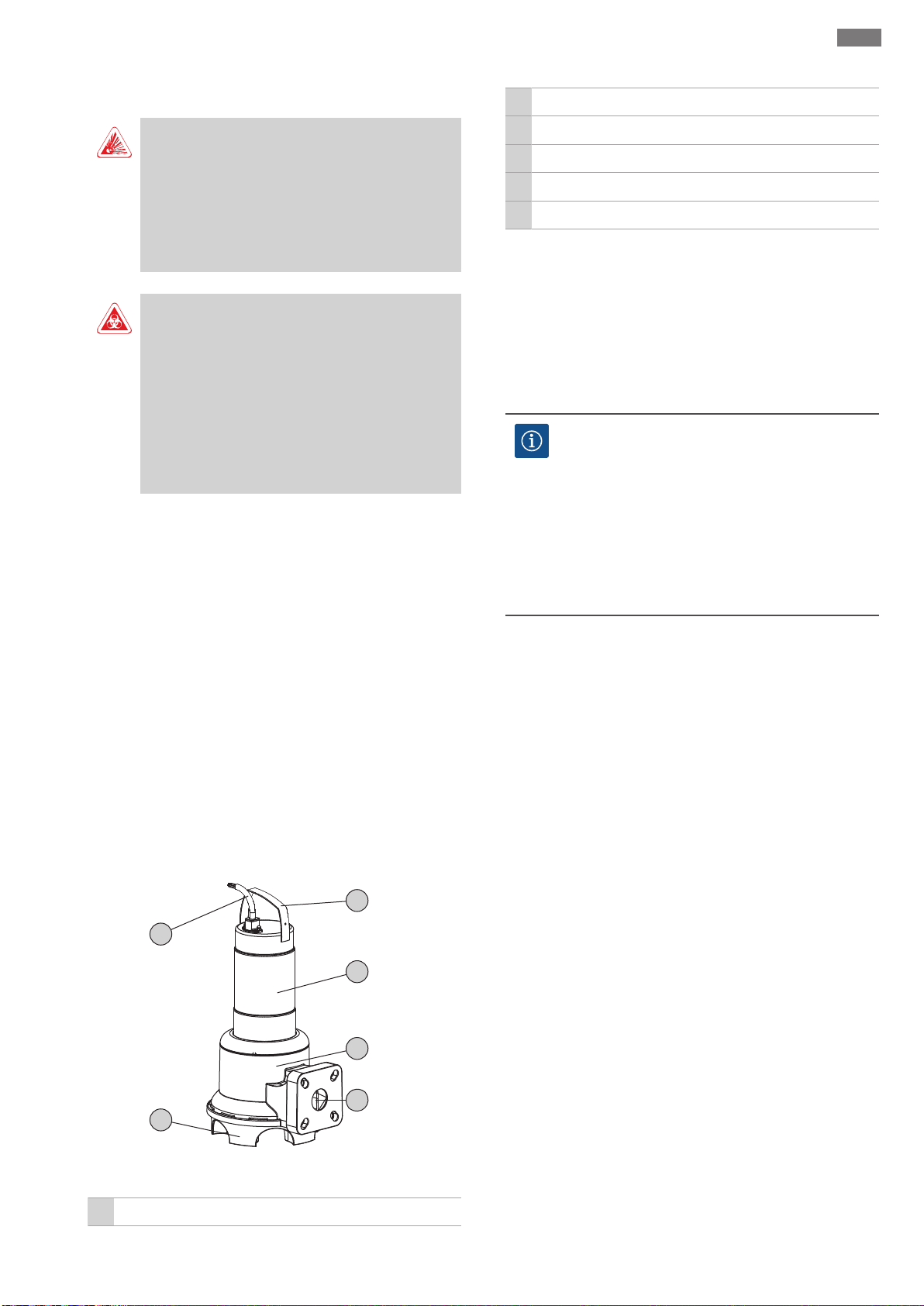
4
5
6
1
2
3
3.2 Improper use
DANGER
Explosion due to pumping of explosive fluids!
Pumping of highly flammable and explosive fluids
(gasoline, kerosene, etc.) in pure form is strictly pro-
hibited. There is a risk of fatal injury due to explo-
sion! The pumps are not designed for these fluids.
DANGER
Danger due to fluids hazardous to health!
If the pump is used in fluids hazardous to health, de-
contaminate the pump after dismantling and before
carrying out any other work! There is danger to life!
Observe the specifications in the work regulations!
The operator must make sure that the personnel has
received and read the work regulations!
The submersible pumps must not be used for pumping:
▪Drinking water
▪Fluids containing hard components (such as stones,
wood, metal, etc.)
▪Fluids containing large quantities of abrasive contents
(e.g. sand, gavel)
Intended use also includes compliance with this
manual. Any other use is regarded as non-compliant
with the intended use.
4 Product description
4.1 Design
Submersible sewage pump as a submersible monobloc
unit for intermittent operation for wet well installation.
2 Motor housing
3 Hydraulics housing
4 Pressure port
5 Pump support foot, integrated in hydraulics housing
6 Power supply cable
4.1.1 Hydraulics
Rotodynamic hydraulics with vortex impeller and hori-
zontal flange connection on the pressure side. The
screwed connection is integrated in the pressure port.
The hydraulics are not self-priming, in other words, the
fluid must flow in either automatically or with supply
pressure.
NOTICE
Combined connection for DN50 and DN65!
The RexaUNIV06 is equipped with a DN50/65
combined connection. The factory setting of the
connection is DN65. To use the pump with a DN50
connection, press the nuts in the flange inwards
onto the small hole circle. The flange can be reset to
DN65 at any time!
4.1.2 Motor
The drive versions used are single-phase current and
three-phase current surface-cooled motors. The motor
is cooled by the fluid around it. The waste heat is trans-
ferred directly to the fluid via the motor housing. The
motor may emerge during operation.
With single-phase AC motors, the operating capacitor
is integrated in the motor. The connection cable is
available in the following versions:
▪Single-phase version:
– With shockproof plug
– With a shockproof plug and fitted with a float switch
▪Three-phase version:
– With bare cable end
– With CEE plug and fitted with a float switch
4.1.3 Seal
Fig.1: Overview
1 Handle/attachment point
Installation and operating instructions Wilo-Rexa UNI 9
Different designs are used for the seal to the fluid and
the motor compartment:
▪RexaUNIV05: A rotary shaft seal is used on the motor
side, a mechanical seal is used on the fluid side.
▪RexaUNIV06: A mechanical seal is used on the motor
side and the fluid side.
The sealing chamber between both seals is filled with
medical white oil.
Page 10

en Product description
4.1.4 Material
▪Pump housing: PP-GF30
▪Impeller: PP-GF30
▪Motor housing: 1.4301
▪Shaft: 1.4401
▪Seal on the fluid side: SiC/SiC
▪Seal on the motor side: NBR (V05), C/Cr (V06)
▪Seal, static: NBR
4.1.5 Fitted accessories
Float switch
In the “A” version the pump is equipped with a float
switch. Depending on the fill level, it is possible to
switch the pump on and off automatically, by using the
float switch.
Plug
In the “P” and “A” version, a shockproof plug is at-
tached for single-phase AC motors and a CEE plug is
attached for three-phase motors The plug is designed
for use in commercially available shock-proof or CEE
sockets and is not overflow-proof.
4.2 Monitoring devices
Monitoring of motor winding
The thermal motor monitoring protects the motor
winding from overheating. Temperature limiting with
bimetallic strip is fitted as standard.
Thermal motor monitoring is self-switching for single-
phase current motors. I.e. if the motor is switched off
due to overheating and then cools down, it is automat-
ically switched on again.
For three-phase current motors, the thermal motor
monitoring must be connected in the switchgear or
plug.
time. The switching cycle has a duration of 10min.
If two values (e.g. S325%/120s) are specified, the first
value relates to the operating time. The second value
specifies the max. period of the switching cycle.
4.4 Operation with frequency converter
Operation on the frequency converter is not permitted.
4.5 Operation in an explosive atmosphere
Operation in an explosive atmosphere is not permitted.
4.6 Technical data
General
Mains connection [U/f] See rating plate
Power consumption [P1] See rating plate
Rated power [P2] See rating plate
Maximum delivery head
See rating plate
[H]
Max. volume flow [Q] See rating plate
Activation type [AT] See rating plate
Fluid temperature [t] 3...40 °C
Protection class IP68
Insulation class [Cl.] F
Speed [n] See rating plate
Max. switching fre-
30/h
quency
Max. immersion depth
See rating plate
[8]
Cable length (standard
10 m
version)
Explosion protection -
Operating modes
4.3 Operating modes
Operating mode S1: Continuous duty
The pump can operate continuously at the rated load
without exceeding the permissible temperature.
Operating mode S2: Short-time duty
The maximum operating period is specified in minutes,
e.g.S2-15. The pause must last until the machine tem-
perature no longer differs from the temperature of the
coolant by more than 2K.
Operating mode S3: Intermittent periodic duty
Immersed [OTs] S1
Non-immersed [OTe] S2-15, S3 10%*
Pressure connection
UNIV05... DN50, PN10
UNIV06... DN50/65, PN10
* Operating mode S325% is permitted if the necessary
motor cooling is guaranteed before the motor is
switched on again! To ensure the required cooling, the
motor must be completely immersed for at least 1min.!
4.7 Type key
This operating mode defines a switching cycle in a
combination of periods of operation and standstill.
Specified value (e.g. S325%) relates to the operating
10 WILO SE 2017-03
Example: Wilo-Rexa UNI V05/T06-540/P
UNI Series
Page 11

Transportation and storage en
Example: Wilo-Rexa UNI V05/T06-540/P
V Impeller= vortex impeller
05 Nominal diameter of pressure connection
T Mains connection version: M=1~, T=3~
06 /10=Rated power P2 in kW
5 Frequency mains connection: 5=50Hz, 6=60Hz
40 Code for rated voltage
Additional electrical equipment:
without= with free cable end
P
A= with float switch and plug
P= with plug
4.8 Scope of delivery
▪Pump with 10m cable
▪Single-phase version with
– Shockproof plug
– Float switch and shockproof plug
▪Three-phase version with
– Bare cable end
– Float switch and CEE plug
▪Installation and operating instructions
4.9 Accessories
▪Cable lengths in fixed length increments of 10m to
max. 30m in the single-phase current version or max.
50m in the three-phase version
▪Suspension unit
▪Level control devices
▪Fixation accessories and chains
▪Switchgear, relays and plugs
5 Transportation and storage
5.1 Delivery
After receiving the shipment, this must be checked im-
mediately for defects (damage, completeness). Defects
must be noted on the freight documentation! Further-
more, defects must be notified to the transport com-
pany or the manufacturer immediately on the day of
receipt of shipment. Subsequently notified defects can
no longer be asserted.
5.2 Transport
WARNING
Standing beneath suspended loads!
Never allow anyone to stand under suspended loads!
Danger of (serious) injuries caused by falling parts.
Loads may not be carried over work places where
people are present!
WARNING
Head and foot injuries due to lack of protect-
ive equipment!
Danger of (serious) injuries during work. Wear the
following protective equipment:
• Safety shoes
• Safety helmet must be used if lifting equipment
are used!
NOTICE
Only use lifting equipment in a technically
sound condition!
Only use lifting equipment in a technically sound
condition for lifting, lowering and transporting the
pump. Ensure that the pump does not become
jammed during lifting and lowering. Do not exceed
the max. permissible bearing capacity of the lifting
equipment!
CAUTION
Soaked packaging may tear!
As a result, the device may fall on the ground unpro-
tected and may be damaged. Soaked packaging
must be lifted carefully and replaced immediately!
Only remove the outer packaging at the place of util-
isation to ensure that the pump is not damaged during
transport. Use tear-proof plastic sacks of sufficient size
to package used pumps for transport in a leak-proof
manner.
The following points must also be observed:
Installation and operating instructions Wilo-Rexa UNI 11
Page 12

en Installation and electrical connection
Newly supplied pumps can be stored for one year. Con-
tact customer service to store the pump for more than
one year.
The following must be observed for storage:
▪Securely position the pump on a firm bearing surface.
Store pumps with pump support foot in an upright pos-
ition, store pumps without pump support foot in a hori-
zontal position. Secure the pump against falling over
and slipping!
▪The max. storage temperature is -15°C to +60°C at a
max. relative humidity of 90%, non-condensing.
Fig.2: Attachment point
▪Adhere to the applicable national safety regulations.
▪Use legally specified and approved lifting gear.
▪Select the lifting gear based on the existing conditions
(weather, attachment point, load, etc.).
▪Only attach the lifting gear to the attachment point. Fix
with a shackle.
▪Use lifting equipment with sufficient bearing capacity.
▪The stability of the lifting equipment must be ensured
during operation.
▪When using lifting equipment, a second person must be
present to coordinate the procedure if required (e.g. if
the operator’s field of vision is blocked).
5.3 Storage
DANGER
Danger due to fluids hazardous to health!
If the pump is used in fluids hazardous to health, de-
contaminate the pump after dismantling and before
carrying out any other work! There is danger to life!
Observe the specifications in the work regulations!
The operator must make sure that the personnel has
received and read the work regulations!
Frost-proof storage at a temperature of 5°C to 25°C
with relative humidity of 40% to 50% is recommen-
ded.
▪Do not store the pump in rooms in which welding work
is carried out. The resulting gases or radiation can cor-
rode the elastomer parts and coatings.
▪Seal the suction and pressure connection tightly.
▪Protect power supply cables against kinking and dam-
age.
▪Protect the pump from direct sunlight and heat. Ex-
treme heat can cause damage to the impellers and the
coating!
▪Impellers must be turned by 180° at regular intervals
(3–6months). This prevents jamming of the bearings
and renews the lubrication film of the mechanical seal.
WARNING!There is a risk of injury due to edges on
the impeller and suction port!
▪Elastomer parts and the coating are subject to natural
brittleness. Contact customer service if the pump must
be stored for more than 6months.
After storage, remove any dust and oil from the pump
and check the coating for damage. Repair damaged
coatings before further use.
6 Installation and electrical connection
WARNING
Sharp edges on the impeller and suction port
Sharp edges can form on the impeller and suction
port. There is danger of limbs being cut-off! Pro-
tective gloves must be worn to protect from cuts.
CAUTION
Total damage due to moisture ingress
Moisture ingress in the power supply cable damages
the power supply cable and the pump! Never im-
merse the end of the power supply cable in a fluid
and firmly seal it during storage.
12 WILO SE 2017-03
6.1 Personnel qualifications
▪Electrical work: Electrical work must be carried out by a
qualified electrician (in accordance with EN50110-1).
▪Installation-/dismantling: The technician must be
trained in the use of the necessary tools and mounting
materials for the relevant construction site.
6.2 Installation types
▪Vertical stationary wet well installation with suspension
unit
▪Vertical portable wet well installation with pump sup-
port foot
The following installation types are not allowed:
Page 13

Installation and electrical connection en
▪Dry well installation
▪Horizontal installation
6.3 Operator responsibilities
▪Observe locally applicable accident prevention and
safety regulations of trade associations.
▪Observe all regulations for working with heavy loads
and under suspended loads.
▪Provide protective equipment and ensure that the pro-
tective equipment is worn by personnel.
▪Observe local sewage technology regulations for the
operation of sewage systems.
▪Avoid pressure surges!
Pressure surges can occur in long discharge pipelines
with steep terrain. These pressure surges can lead to
the destruction of the pump!
▪Ensure the cooling time of the motor depending on the
operating conditions and the size of the pump cham-
ber.
▪Structural components and foundations must be of
sufficient stability in order to allow the device to be
fixed securely and functionally. The operator is re-
sponsible for the provision and suitability of the struc-
tural component/foundation!
▪Check that the available consulting documents (install-
ation plans, design of the operating space, inflow con-
ditions) are complete and correct.
6.4 Installation
DANGER
Potentially fatal danger due to dangerous
autonomous work!
Work in chambers and narrow rooms as well as work
involving risk of falling are dangerous work. Such
work may not be carried out autonomously! A
second person must be present for safety reasons.
WARNING
Hand and foot injuries due to lack of protect-
ive equipment!
Danger of (serious) injuries during work. Wear the
following protective equipment:
• Safety gloves against cuts
• Safety shoes
• Safety helmet must be used if lifting equipment
are used!
NOTICE
Only use lifting equipment in a technically
sound condition!
Only use lifting equipment in a technically sound
condition for lifting, lowering and transporting the
pump. Ensure that the pump does not become
jammed during lifting and lowering. Do not exceed
the max. permissible bearing capacity of the lifting
equipment!
NOTICE
Emerging of the motor during operation
If the motor emerges during operation, the specific-
ations for “Operating mode non-immersed” must be
complied with!
To ensure that the motor is cooled during continu-
ous duty, the motor must be immersed completely
before switching it on again!
▪Prepare operating space/installation location as follows:
– Clean, free of coarse solids
– Dry well
– Frost-free
– Decontaminated
▪Take immediate countermeasures if there is a build-up
of toxic or suffocating gases!
▪Use the handle for lifting, lowering and transporting the
pump. Never carry or drag the pump by the power sup-
ply cable!
▪It must be possible to attach lifting equipment safely.
The storage place and the operating space/installation
site must be accessible with the lifting equipment. The
set-down location must have a solid bearing surface.
▪Attach the lifting gear to the handle using a shackle.
Only use lifting gear which has been technically ap-
proved.
▪The routed power supply cables must allow safe opera-
tion. Check whether the cable cross-section and the
cable length are sufficient for the selected installation
type.
▪The corresponding IP class must be observed when us-
ing switchgear. Install the switchgear overflow-proof
and outside potentially explosive areas!
▪Avoid air intake into the fluid, use baffles or deflector
plates for the inlet. Air which has entered the system
can collect in the pipe system and lead to impermissible
operating conditions. Air pockets must be removed via
ventilation systems!
Installation and operating instructions Wilo-Rexa UNI 13
Page 14

en Installation and electrical connection
d
A
2
A
1
1
▪A dry run of the pump is prohibited! Avoid air pockets in
the hydraulics housing or in the pipe system. Ensure the
water level never falls below the minimum. The install-
ation of a dry-running protection is recommended!
6.4.1 Indications for double pump operation
If several pumps are used in an operating space, min-
imum distances between the pumps and the wall must
be complied with. Here there is a difference in the dis-
tances depending on the type of system: Alternating
operation or parallel operation.
1. Push the nut inwards onto the small hole circle using a
screwdriver.
▶ The flange connection is reset to DN50.
6.4.3 Maintenance tasks
After a storage period of more than 6months, check
the oil in the sealing chamber prior to installation:
Fig.5: Check the oil
Fig.3: Minimum distances
d Diameter hydraulics housing
Minimum distance from the wall:
A
- alternating operation: min. 0.3×d
1
- parallel operation: min. 1×d
Distance to discharge pipelines
A
- alternating operation: min. 1.5×d
2
- parallel operation: min. 2×d
6.4.2 Note on DN50/65 combination flange
The Rexa UNI V06... is equipped with a DN50/65 com-
bination flange. The nuts on the combination flange are
factory-set to the DN65 flange. For use with a DN50
flange, adjust the nuts at the flange. The flange can be
reset to DN65 at any time!
1 Screw plug sealing chamber
‡ Pump is not installed.
‡ Pump is not connected to the mains.
‡ Protective equipment has been put on!
1. Place the pump horizontally on a firm surface. The
screw plug points upwards. WARNING!Risk of hands
being crushed. Ensure that the pump cannot fall over
or slip away!
2. Unscrew the screw plug.
3. Place a suitable tank to collect the operating fluid.
4. Drain the operating fluid: Rotate the pump until the
opening points downwards.
5. Check the operating fluid:
⇒ If the operating fluid is clear, reuse operating fluid.
⇒ If the operating fluid is contaminated (black), fill
with new operating fluid. Dispose of operating
fluid in accordance with the local regulations!
⇒ Notify customer service if an operating fluid con-
tains metal chips!
6. Pour in operating fluid: Rotate the pump until the
opening points upwards. Fill-in the operating fluid into
the opening.
Fig.4: Adjust combination flange
‡ No accessories mounted on flange.
‡ Nut is freely accessible.
14 WILO SE 2017-03
⇒ Comply with the specifications for operating fluid
locations and quantity! When recycling the operating fluid, check the quantity and if required adjust
it!
Page 15

Installation and electrical connection en
1
5
6
S1
S2/S3
3
4
2
7. Clean the screw plug, replace the seal ring and screw it
back in. Max. tightening torque: 8Nm!
6.4.4 Stationary wet well installation
NOTICE
Delivery problems due to water level being
too low
The hydraulics are self-venting. As a result, smaller
air cushions are dissolved during the pumping pro-
cess. If the level of the fluid is lowered too much, the
volume flow can be interrupted. The minimum per-
missible water level must reach the upper edge of
the hydraulics housing!
The pump is installed in the fluid for the wet well in-
stallation. For this, a suspension unit must be installed
in the chamber. On the pressure side, the on-site pipe
system is connected to the suspension unit and on the
suction side to the pump. The connected pipe system
must be self-supporting. The suspension unit must not
support the pipe system!
CAUTION!If the motor emerges during operation,
observe the operating mode for non-immersed oper-
ation (S2-15, S3 10%*)!
* Operating mode S325% is permitted if the necessary
motor cooling is guaranteed before the motor is
switched on again! To ensure the required cooling, the
motor must be completely immersed for at least 1min.!
Work steps
4 Guide pipe (provided by the customer)
5 Lifting equipment
6 Attachment point for the lifting equipment
CAUTION
Damage to the pump due to incorrect install-
ation
Observe the following points during the installation
of the pump:
• Observe the max. permissible tightening torque:
15Nm (V05) or 25Nm (V06)
• Do not insert an additional gasket between the
flange and the accessories! A gasket is mounted
on the pump flange!
• Only use accessories with a flange shape in accordance with EN1092-2, type A. The use of
other flange shapes is not permitted!
‡ Operating space/installation location is prepared for the
installation.
‡ Suspension unit and pipe system were installed.
‡ Pump is prepared for operation on the suspension unit.
1. Use a shackle to attach the lifting equipment to the at-
tachment point of the pump.
2. Lift the pump, swivel it above the chamber opening and
slowly lower the guide claw onto the guide pipe.
3. Lower the pump until it sets on the suspension unit and
is connected automatically. CAUTION!Hold the power
supply cables slightly taut when lowering the pump!
4. Loosen the lifting equipment from the lifting gear and
secure it at the chamber outlet against falling.
5. Have the power supply cables routed into the chamber
by a qualified electrician and route it outside properly
from the chamber.
▶ The pump is installed, the qualified electrician can
make the electrical connection.
6.4.5 Portable wet well installation
WARNING
Risk of burns from hot surfaces!
Motor housing can become hot during operation. It
Fig.6: Wet well installation, stationary
1 Suspension unit
2 Non-return valve
3 Stop valve
may cause burns. Allow the pump to cool down at
ambient temperature after switching it off!
Installation and operating instructions Wilo-Rexa UNI 15
Page 16

en Installation and electrical connection
1
2
3
4
5
S1
S2, S3
6
WARNING
Separation of pressure hose!
Separation or movement of the pressure hose can
lead to (serious) injuries. Securely attach the pres-
sure hose to the outlet! Prevent buckling of the
pressure hose.
NOTICE
Delivery problems due to water level being
too low
The hydraulics are self-venting. As a result, smaller
air cushions are dissolved during the pumping pro-
cess. If the level of the fluid is lowered too much, the
volume flow can be interrupted. The minimum per-
missible water level must reach the upper edge of
the hydraulics housing!
For portable installation, the pump is equipped with a
pump support foot. The pump support foot ensures
minimum ground clearance in the suction area and en-
ables secure footing if placed on a solid bearing sur-
face. In this installation type, the pump can be installed
anywhere in the operating space/installation site. A
hard base must be used at the installation location to
prevent sinking in case of soft bearing surfaces. A pres-
sure hose is connected on the pressure side.
CAUTION!If the motor emerges during operation,
observe the operating mode for non-immersed oper-
ation (S2-15, S3 10%*)!
* Operating mode S325% is permitted if the necessary
motor cooling is guaranteed before the motor is
switched on again! To ensure the required cooling, the
motor must be completely immersed for at least 1min.!
Work steps
1 Pump with integrated pump support foot
2 Pipe elbow with hose connection or Storz pipe coupling
3 Storz hose coupling
4 Pressure hose
5 Attachment point
6 Lifting equipment
CAUTION
Damage to the pump due to incorrect install-
ation
Observe the following points during the installation
of the pump:
• Observe the max. permissible tightening torque:
15Nm (V05) or 25Nm (V06)
• Do not insert an additional gasket between the
flange and the accessories! A gasket is mounted
on the pump flange!
• Only use accessories with a flange shape in accordance with EN1092-2, type A. The use of
other flange shapes is not permitted!
‡ Pressure connection prepared: Pipe elbow with hose
connection or pipe elbow with Storz coupling mounted.
1. Use a shackle to attach the lifting equipment to the at-
tachment point of the pump.
2. Lift the pump and lower it at the intended location
(chamber, pit).
3. Place the pump on a solid bearing surface. CAU-
TION!Sinking must be prevented!
4. Lay the pressure hose and fasten it to a certain point
(e.g. drainage). DANGER!Separation or movement of
the pressure hose can lead to (serious) injuries! Se-
curely attach the pressure hose to the outlet.
5. Lay the power supply cable properly. CAUTION!Do not
damage the power supply cable!
▶ The pump is installed, the qualified electrician can
make the electrical connection.
6.4.6 Level control
With a level control device, the current fill levels are de-
termined and the pump is switched on and off auto-
matically depending on the fill levels. Fill levels are re-
corded by using different sensor types (float switches,
pressure and ultrasound measurements or electrodes).
The following must be observed when using a level
Fig.7: Wet well installation, portable
16 WILO SE 2017-03
control device:
▪Float switches can move freely!
Page 17

Installation and electrical connection en
▪The water level must not fall below the minimum per-
missible!
▪The maximum switching frequency must not be ex-
ceeded!
▪If the fill levels fluctuate strongly, a level control with
two measuring points is recommended. This makes it
possible to achieve larger differential gaps.
Use of attached float switch
The “A” version is equipped with a float switch. The
pump is switched on and off depending on the fill level.
The switching level is determined by the cable length
of the float switch.
Use of on-site level controls
When using an on-site level control device, refer to the
manufacturer’s own installation and operating instruc-
tions for specifications on the installation.
6.4.7 Dry-running protection
Dry-running protection must prevent the pump from
operating without fluid and air from entering the hy-
draulics. Minimum permissible fill level must be de-
termined with the help of a signal transmitter. Once the
specified limit value is reached, the pump must be de-
activated with an appropriate signal. Dry-running pro-
tection can expand the available level controls by an
additional measuring point or function as an independ-
ent switch-off device. Depending on the system secur-
ity, the pump can be restarted automatically or manu-
ally. Installation of a dry-running protection is recom-
mended for optimum operational reliability.
6.5 Electrical connection
DANGER
Risk of death due to electrocution!
Improper conduct when carrying out electrical work
can lead to death due to electric shock! Electrical
work must be carried out by a qualified electrician in
accordance with the locally applicable regulations.
▪The mains connection must match the specifications
on the rating plate.
▪Power supply on mains side for three-phase current
motors with clockwise rotating field.
▪Lay the power supply cables in accordance with the
locally applicable regulations and connect them ac-
cording to the wire assignment.
▪Connect the monitoring devices and check their func-
tion.
▪Earth the device properly in accordance with the locally
applicable regulations.
6.5.1 Fuse on mains side
Circuit breaker
The size of the circuit breakers conforms to the rated
current of the pump. The switching characteristics
should comply with group B or C. Observe local regula-
tions.
Motor protection switch
Make provision for an on-site motor protection switch
for devices without a plug! The minimum requirement
is a thermal relay/motor protection switch with tem-
perature compensation, differential triggering and
anti-reactivation device in accordance with the local
regulations. In case of sensitive mains, make provision
for the installation on-site of other protective equip-
ment (e.g. overvoltage, undervoltage or phase failure
relay, etc.).
Residual-current device (RCD)
Comply with the regulations of the local energy supply
company! The use of a residual-current device is re-
commended.
If persons come into contact with the device and con-
ductive fluids, secure the connection with a residual-
current device (RCD).
6.5.2 Maintenance tasks
Carry out the following maintenance tasks prior to in-
stallation:
▪Check the insulation resistance of the motor winding.
▪Test the resistor of the temperature sensor.
If the measured values differ from the specifications,
moisture may have penetrated into the motor or the
power supply cable or the monitoring device is defect-
ive. Contact customer service in the event of a fault.
6.5.2.1 Checking the insulation resistance of the motor winding
Use an insulation tester to measure the insulation res-
istance (measuring voltage = 1000V). Observe the fol-
lowing values:
▪At the time of initial commissioning: Insulation resist-
ance may not be less than 20MΩ.
▪For further measurements: Value must be greater than
2MΩ.
NOTICE!For motors with an integrated capacitor,
short-circuit the windings prior to checking!
Installation and operating instructions Wilo-Rexa UNI 17
Page 18

en Installation and electrical connection
U1/Z1
bn
U2
bu
C
r
M 1~
gn-ye
LNPE
W
5
1
2
V
4
U
3
M 3~
gn-ye
L3L2 2120L1PE
250 V (AC); 2,5 A; cos φ = 1
6.5.2.2 Test the resistor of the temperature sensor
Measure the resistor of the temperature sensors with
an ohmmeter. The bimetallic strips must have a meas-
ured value of 0Ohm (passage).
6.5.3 Connection of the single-phase motor
Fig.8: Connection diagram single-phase motor
Wire colour Terminal
Brown (bn) L
Blue (bu) N
2 21 WSK
3 U L1
4 V L2
5 W L3
Green/yellow (gn-
ye)
For three-phase current motors, a clockwise rotating
field must be available. The three-phase version is
equipped with a CEE plug or with a free cable end:
▪If a CEE plug is supplied, connection to the mains is es-
tablished by inserting the plug into a socket. The plug is
not overflow-proof. Install the socket so that it is
overflow-proof! Observe the information on the pro-
tection class (IP) of the plug.
▪If there is a free cable-end, the pump must be connec-
ted directly to the switchgear. DANGER!If the pump is
connected directly to the switchgear, arrange for the
electrical connection to be carried out by a qualified
electrician!
Earth PE
Green/yellow (gn-
ye)
The single-phase current version is equipped with a
shockproof plug. The connection to the mains is estab-
lished by inserting the plug into a socket. The plug is
not overflow-proof. Install the socket so that it is
overflow-proof! Observe the information on the pro-
tection class (IP) of the plug.
DANGER!If the pump is connected directly to the
switchgear, dismantle the plug and arrange for the
electrical connection to be carried out by a qualified
electrician!
6.5.4 Connection three-phase motor
Fig.9: Connection diagram three-phase motor
Wire number Designation Terminal
1 20 WSK
Earth
6.5.5 Monitoring equipment connection
All monitoring equipment must be connected!
6.5.5.1 Monitoring of motor winding
Single-phase current motor
Thermal motor monitoring is self-switching for single-
phase current motors. The monitoring function is al-
ways active and does not need to be connected separ-
ately.
Three-phase current motor with bimetallic strip
Bimetallic strips are connected in the switchgear itself
or via an evaluation relay.
Connection values: max. 250V(AC), 2.5A, cos φ = 1
When the threshold is reached, deactivation must
take place.
In the version with an attached plug, the thermal motor
monitoring is pre-wired and set to the correct value in
the plug.
6.5.6 Motor protection adjustment
Motor protection must be set depending on the selec-
ted activation type.
6.5.6.1 Direct activation
At full load, set the motor protection switch to the
rated current (see rating plate). At partial load, it is re-
commended to set the motor protection switch 5%
above the current measured at the duty point.
18 WILO SE 2017-03
Page 19

Commissioning en
6.5.6.2 Soft starter
At full load, set the motor protection switch to the
rated current (see rating plate). At partial load, it is re-
commended to set the motor protection switch 5%
above the current measured at the duty point. The fol-
lowing must also be observed:
▪Power consumption must always be below the rated
current.
▪Complete starting and stopping within 30s.
▪To avoid power dissipation, bypass the electronic
starter (soft start) once normal operation is reached.
6.5.7 Operation with frequency converter
Operation on the frequency converter is not permitted.
7 Commissioning
WARNING
Foot injuries due to lack of protective equip-
ment!
Danger of (serious) injuries during work. Wear safety
shoes!
7.1 Personnel qualifications
▪Electrical work: Electrical work must be carried out by a
qualified electrician (in accordance with EN50110-1).
▪Operation/control: Operating personnel must be in-
structed in the functioning of the complete system.
7.2 Operator responsibilities
▪Providing installation and operating instructions by the
pump or at a place specially reserved for it.
▪Making the installation and operating instructions
available in the language of the personnel.
▪Making sure that the installation and operating instruc-
tions are read and understood by all personnel.
▪All safety devices and emergency cut-outs on the sys-
tem-side must be active and checked to ensure that
they work properly.
▪The pump is suitable for use under the specified oper-
ating conditions.
7.3 Direction of rotation check (for three-phase current motors only)
The pump is factory-checked and adjusted to the cor-
rect direction of rotation for a clockwise rotating field.
Connection is made in accordance with the specifica-
tions in chapter “Electrical connection”.
Direction of rotation check
A qualified electrician checks the rotating field at the
mains connection with a rotating field-test device. For
the correct direction of rotation, a clockwise rotating
field must be available at the mains connection. The
pump is not approved for operation with a counter-
clockwise rotating field! CAUTION!If the direction of
rotation is checked with a test run, comply with the
ambient and operating conditions!
Incorrect direction of rotation
If the direction of rotation is incorrect, change the con-
nection as follows:
▪Swap two phases for motors with direct starting.
▪Swap the connections of two windings (e.g. U1/V1 and
U2/V2) for star-delta activation motors.
7.4 Before switching on
Check the following prior to activation:
▪Check whether the device has been installed properly
and in accordance with the locally applicable regula-
tions:
– Has the pump been earthed?
– Layout of power supply cable tested?
– Electrical connection made properly?
– Mechanical components attached correctly?
▪Check level control:
– Float switches can move freely?
– Switching level tested (pump on, pump off, minimum
water level)?
– Additional dry-running protection installed?
▪Test operating conditions:
– Min./max. temperature of the fluid tested?
– Max. immersion depth tested?
– Operating mode defined depending on the minimum
water level?
– Maximum switching frequency adhered to?
▪Check installation location/operating space:
– Pipe system on the pressure side free of deposits?
– Inlet or pump sump cleaned or free of deposits?
– All gate valves open?
– Minimum water level defined and monitored?
The hydraulics housing must be filled completely
with the fluid and there must be no air cushions in
the hydraulics. NOTICE!Provide suitable venting
devices if there is a risk of air cushions being
formed in the system!
7.5 Switch on and off
During the start process, the rated current is temporar-
ily exceeded. During operation, the rated current may
Installation and operating instructions Wilo-Rexa UNI 19
Page 20

en Decommissioning/dismantling
no longer be exceeded. CAUTION!If the pump does
not start, switch off the pump immediately. Remove
the fault before reactivating the pump!
Place pumps which are installed as portable pumps on a
firm surface so they are level. If pumps have fallen over,
place them upright again before activating them. Se-
curely attach the pump with screws in case of difficult
surfaces.
Pump with attached float switch and plug
▪Single-phase current version: After inserting the plug
into the socket, the pump is ready for operation. The
pump is switched on and off automatically depending
on the fill level.
▪Three-phase version: After inserting the plug into the
socket, the pump is ready for operation. The pump is
controlled via two switches on the plug:
– HAND/AUTO: Determines if the pump is switched on
and off directly (HAND) or depending on the fill level
(AUTO).
– ON/OFF: Switch pump on and off.
Pump with attached plug
▪Single-phase current version: After inserting the plug in
the socket, the pump is switched on.
▪Three-phase version: After inserting the plug into the
socket, the pump is ready for operation. The pump is
switched on and off with the ON/OFF switch.
Pumps with free cable end
The pump must be switched on and off using a separ-
ate operating point (on/off switch, switchgear)
provided by the customer.
7.6 During operation
WARNING
Amputation of limbs due to rotating com-
ponents!
No persons must be present in the work area of the
pump! There is risk of (serious) injuries due to rotat-
ing components! No persons must be present in the
work area of the pump during start-up or operation.
NOTICE
Delivery problems due to water level being
too low
The hydraulics are self-venting. As a result, smaller
air cushions are dissolved during the pumping pro-
cess. If the level of the fluid is lowered too much, the
volume flow can be interrupted. The minimum per-
missible water level must reach the upper edge of
the hydraulics housing!
When operating the pump, observe the locally applic-
able regulations on the following topics:
▪Work safety
▪Accident prevention
▪Handling electrical machines
Strictly adhere to the responsibilities of the personnel
specified by the operator. All personnel are responsible
for ensuring that the responsibilities of the personnel
and the regulations are observed!
Due to their design, centrifugal pumps have rotating
parts that are easily accessible. Depending on the oper-
ating condition, sharp edges can develop on these
parts. WARNING!This can lead to cuts and limbs may
be amputated and severed! Check the following at
regular intervals:
▪Operating voltage (+/-10% of the rated voltage)
▪Frequency (+/-2% of the rated frequency)
▪Power consumption between individual phases (max.
5%)
▪Voltage difference between the individual phases
(max.1%)
▪Max. switching frequency
▪Minimum water submersion depending on the operat-
ing mode
▪Inlet: no air intake
▪Level control device/dry-running protection: Switching
points
▪Quiet/low-vibration running
▪All gate valves open
8 Decommissioning/dismantling
WARNING
Risk of burns from hot surfaces!
Motor housing can become hot during operation. It
may cause burns. Allow the pump to cool down at
ambient temperature after switching it off!
20 WILO SE 2017-03
8.1 Personnel qualifications
▪Operation/control: Operating personnel must be in-
structed in the functioning of the complete system.
▪Electrical work: Electrical work must be carried out by a
qualified electrician (in accordance with EN50110-1).
Page 21

Decommissioning/dismantling en
▪Installation-/dismantling: The technician must be
trained in the use of the necessary tools and mounting
materials for the relevant construction site.
8.2 Operator responsibilities
▪Locally applicable accident prevention and safety regu-
lations of trade associations.
▪Observe regulations for working with heavy loads and
under suspended loads.
▪Provide the necessary protective equipment and make
sure that the personnel wears it.
▪Provide adequate aeration in closed rooms.
▪Take immediate countermeasures if there is a build-up
of toxic or suffocating gases!
8.3 Decommissioning
The pump is deactivated during decommissioning, but
remains installed. This ensures that the pump is always
ready for operation.
‡ To protect the pump from frost and ice, always im-
merse the pump completely in the fluid.
‡ Temperature of the fluid must always be above +3°C.
1. Switch off the pump at the operating point.
DANGER
Risk of death due to electrocution!
Improper conduct when carrying out electrical work
can lead to death due to electric shock! Electrical
work must be carried out by a qualified electrician in
accordance with the locally applicable regulations.
DANGER
Potentially fatal danger due to dangerous
autonomous work!
Work in chambers and narrow rooms as well as work
involving risk of falling are dangerous work. Such
work may not be carried out autonomously! A
second person must be present for safety reasons.
WARNING
Risk of burns from hot surfaces!
Motor housing can become hot during operation. It
may cause burns. Allow the pump to cool down at
ambient temperature after switching it off!
2. Secure the operating point against being switched on
again by unauthorised persons (e.g. lock main switch).
▶ The pump is out of operation and can now be dis-
mantled.
If the pump remains installed after decommissioning,
observe the following:
▪Ensure that the prerequisites for decommissioning are
maintained for the complete period of decommission-
ing. If these prerequisites cannot be guaranteed, dis-
mantle the pump after decommissioning!
▪For an extended period of decommissioning, carry out a
5-minute function test at regular intervals (monthly to
quarterly). CAUTION!A function test may only be car-
ried out under the applicable operating conditions. A
dry run is not permitted! Non-compliance can result
in irreparable damage!
8.4 Removal
DANGER
Danger due to fluids hazardous to health!
If the pump is used in fluids hazardous to health, de-
contaminate the pump after dismantling and before
carrying out any other work! There is danger to life!
Observe the specifications in the work regulations!
The operator must make sure that the personnel has
received and read the work regulations!
NOTICE
Only use lifting equipment in a technically
sound condition!
Only use lifting equipment in a technically sound
condition for lifting, lowering and transporting the
pump. Ensure that the pump does not become
jammed during lifting and lowering. Do not exceed
the max. permissible bearing capacity of the lifting
equipment!
8.4.1 Stationary wet well installation
‡ Pump is decommissioned.
‡ Gate valves on the inlet and pressure side closed.
1. Disconnect the pump from the mains.
2. Attach the lifting equipment to the attachment point.
CAUTION!Never pull on the power supply cable! This
damages the power supply cable!
3. Slowly raise the pump and lift above the guide pipes
from the operating space. CAUTION!The power sup-
ply cable can be damaged while lifting! Hold the
power supply cable slightly taut when lifting!
4. Clean pump thoroughly (see point “Cleaning and disin-
fecting”). DANGER!Disinfect the pump when used in
fluids hazardous to health!
Installation and operating instructions Wilo-Rexa UNI 21
Page 22

en Decommissioning/dismantling
1
2
8.4.2 Portable wet well installation
‡ Pump is taken out of operation.
1. Disconnect the pump from the mains.
2. Roll up the power supply cable and place it over the
motor housing. CAUTION!Never pull on the power
supply cable! This damages the power supply cable!
3. Loosen the pressure pipe from the pressure port.
4. Attach the lifting equipment to the attachment point.
5. Lift the pump from the operating space. CAUTION!The
power supply cable may be squeezed and damaged
when setting the pump down! Pay attention to the
power supply cable when setting the pump down!
6. Clean pump thoroughly (see point “Cleaning and disin-
fecting”). DANGER!Disinfect the pump when used in
fluids hazardous to health!
8.4.3 Clean and disinfect
DANGER
Danger due to fluids hazardous to health!
Danger to life if the pump is used in fluids hazardous
to health! Decontaminate the pump before carrying
out any further work! Wear the following protective
equipment while performing cleaning tasks:
• Closed safety goggles
• Breathing mask
• Protective gloves
⇒ The equipment listed here is the minimum re-
quirement, observe the specifications of the
work regulations! The operator must make
sure that the personnel has received and read
the work regulations!
‡ Pump is dismantled.
‡ The contaminated cleaning water is disposed of in the
sewage in accordance with the locally applicable regulations.
‡ A disinfectant is provided for contaminated pumps.
1. Attach the lifting equipment to the attachment point
of the pump.
2. Lift the pump approximately 30cm above the ground.
3. Spray the pump with clear water from top to bottom.
NOTICE!An appropriate disinfectant must be used
for contaminated pumps! Strictly observe the manu-
facturer’s specifications concerning use!
5. Flush all dirt residue onto the floor of the channel.
6. Allow the pump to dry out.
8.4.3.1 Clean the interior area of the hydraulics
Disassemble the baseplate of the hydraulics for easier
cleaning of the interior area of the hydraulics.
Fig.10: Disassemble baseplate
1 Safety screw
2 Baseplate
1. Place the pump horizontally on a firm surface. WARN-
ING!Risk of hands being crushed. Ensure that the
pump cannot fall over or slip away!
2. Unscrew the safety screw (hexagonal socket4) of the
baseplate half-way, until the bayonet coupling can be
turned.
3. The baseplate is attached with a bayonet coupling.
Turn the baseplate clockwise (to the right) and remove.
4. Rinse the interior area of the hydraulics with clear wa-
ter, remove solids manually. WARNING!Sharp edges
can form on the impeller. This can lead to extremities
being cut off! Wear safety gloves to protect against
cuts!
5. Check correct position of O-ring on the baseplate.
6. Lubricate the O-ring with O-ring grease and set the
baseplate on the hydraulic part.
7. Turn baseplate anticlockwise (to the left). The base-
plate is fixed in place with the bayonet coupling.
8. Screw in the safety screw of the baseplate. Max. tight-
ening torque: 1.5Nm!
▶ Hydraulics cleaned and locked, complete cleaning
tasks.
4. To clean the impeller and the interior pump space,
guide the water jet inside via the pressure port.
22 WILO SE 2017-03
Page 23

Maintenance and repair en
9 Maintenance and repair
DANGER
Danger due to fluids hazardous to health!
If the pump is used in fluids hazardous to health, de-
contaminate the pump after dismantling and before
carrying out any other work! There is danger to life!
Observe the specifications in the work regulations!
The operator must make sure that the personnel has
received and read the work regulations!
NOTICE
Only use lifting equipment in a technically
sound condition!
Only use lifting equipment in a technically sound
condition for lifting, lowering and transporting the
pump. Ensure that the pump does not become
jammed during lifting and lowering. Do not exceed
the max. permissible bearing capacity of the lifting
equipment!
▪Always carry out maintenance tasks in a clean location
with good lighting. It must be possible to position the
pump safely and secure it.
▪Only carry out maintenance tasks mentioned in this in-
stallation and operating instructions.
▪Wear the following protective equipment while per-
forming maintenance tasks:
– Safety goggles
– Safety shoes
– Safety gloves
9.1 Personnel qualifications
▪Electrical work: Electrical work must be carried out by a
qualified electrician (in accordance with EN50110-1).
▪Maintenance tasks: The technician must be familiar
with the use of operating fluids and their disposal. In
addition, the technician must have basic knowledge of
mechanical engineering.
9.2 Operator responsibilities
▪Provide the necessary protective equipment and make
sure that the personnel wears it.
▪Collect operating fluids in suitable tanks and disposed
of properly.
▪Dispose of protective clothing used in accordance with
regulations.
▪Use only original parts of the manufacturer. Use of
parts other than the original parts releases the manu-
facturer from any liability.
▪Collect any leakage of fluid and operating fluid immedi-
ately and dispose of it according to the locally applic-
able guidelines.
▪Provide the tools required.
▪If flammable solvents and cleaning agents are used,
open flames, naked lights and smoking are prohibited.
9.3 Operating fluid
9.3.1 Oil types
Biological white oil is filled-in into the sealing chamber.
The following oil types are recommended when chan-
ging the oil:
▪Aral Autin PL*
▪Shell ONDINA 919
▪Esso MARCOL 52* or 82*
▪BP WHITEMORE WOM 14*
▪Texaco Pharmaceutical 30* or 40*
All oil types marked with “*” are approved for use with
foods in accordance with “USDA-H1”.
9.3.2 Filling quantities
The filling quantities depend on the pump type:
▪RexaUNI V05...: 600ml
▪RexaUNIV06...: 1000ml
9.4 Maintenance intervals
To ensure reliable operation, maintenance tasks must
be carried out regularly. Depending on the real ambient
temperatures, maintenance intervals different from
those mentioned in the contract can be defined! If
strong vibrations occur during operation, the pump and
the installation must be checked regardless of the
defined maintenance intervals.
9.4.1 Maintenance intervals for normal conditions
5years or 1500operating hours
▪Visual inspection of the power supply cable
▪Visual inspection of accessories
▪Visual inspection of the housing for wear
▪Function test of monitoring devices
▪Oil change
9.4.2 Maintenance intervals for use in sewage lifting units
When the pump is used in sewage lifting units inside
buildings or on plots of land, carry out maintenance in-
tervals and measures in accordance with
DINEN12056‑4!
Installation and operating instructions Wilo-Rexa UNI 23
Page 24

en Maintenance and repair
9.4.3 Maintenance intervals for harsh conditions
Under harsh operating conditions, specified mainten-
ance intervals must be shortened if required. Harsh op-
erating conditions include:
▪Fluids with long-fibre components
▪Turbulent inlet (e.g. due to air intake, cavitation)
▪Strongly corroding or abrasive fluids
▪Heavily gas generating fluids
▪Operation at an unfavourable duty point
▪Pressure surges
When using pumps under hard conditions, it is recom-
mended to sign a maintenance contract. Contact cus-
tomer service.
9.5 Maintenance measures
WARNING
Sharp edges on the impeller and suction port
Sharp edges can form on the impeller and suction
port. There is danger of limbs being cut-off! Pro-
tective gloves must be worn to protect from cuts.
WARNING
Hand, foot or eye injuries due to lack of pro-
tective equipment!
Danger of (serious) injuries during work. Wear the
following protective equipment:
• Safety gloves against cuts
• Safety shoes
• Closed safety goggles
The following pre-requisites must be fulfilled prior to
starting maintenance measures:
▪Pump cooled down to the ambient temperature.
▪Pump cleaned thoroughly and disinfected (if required).
9.5.1 Recommended maintenance measures
Regular inspection of power consumption and the op-
erating voltage in all three phases is recommended for
smooth operation. In normal operation, these values
remain constant. Slight fluctuations depend on the
characteristics of the fluid. Power consumption can
provide an early indication of damage or malfunctions
in the impeller, bearings or motor, which can be recti-
fied. Larger voltage fluctuations strain the motor wind-
ing and can cause the pump to break down. Regular in-
spections can therefore largely prevent major second-
ary damage and reduce the risk of total breakdown. In
this regard, it is recommended to use remote monitor-
ing for regular inspections.
9.5.2 Visual inspection of the power supply cable
The power supply cables must be checked for:
▪Bubbles
▪Cracks
▪Scratches
▪Abrasion
▪Crushing
If the power supply cables are damaged, the pump
must be decommissioned immediately! Customer ser-
vice must replace the damaged power supply cable.
The pump may only be started up again once the dam-
age has been properly remedied.
CAUTION!Water may penetrate into the pump due to
the damaged power supply cables! Water ingress
leads to total damage of the pump.
9.5.3 Visual inspection of accessories
Accessories must be checked for:
▪Correct fixation
▪Smooth function
▪Wear symptoms
Detected defects must be repaired immediately or the
accessories must be replaced.
9.5.4 Visual inspection of the housing for wear
The housing parts are not allowed to have any apparent
damage. Contact customer service if defects are detec-
ted!
9.5.5 Function test of the monitoring equipment
To test resistances, the pump must be cooled down to
the ambient temperature!
9.5.5.1 Test the resistor of the temperature sensor
Measure the resistor of the temperature sensors with
an ohmmeter. The bimetallic strips must have a meas-
ured value of 0Ohm (passage).
24 WILO SE 2017-03
Page 25

Faults, causes and remedies en
1
9.5.6 Oil change in sealing chamber
WARNING
Operating fluid under high pressure!
A pressure of several bar can build up in the motor!
This pressure escapes when the screw plugs are
opened. If screw plugs are opened without due cau-
tion, they can be ejected at high speed! To avoid in-
juries, observe the following instructions:
• Adhere to the prescribed sequence of work
steps.
• Unscrew the screw plugs slowly, but never unscrew them completely. As soon as the pressure
escapes (audible whistling or hissing of air), stop
turning the screw plug any further!
• When the pressure has completely dissipated,
fully unscrew the screw plugs.
• Wear closed safety goggles.
WARNING
Scalding due to hot operating fluids!
Hot operating fluids can also spray out when the
pressure is escaping. This can result in scalding! To
avoid injuries, the following instructions must be
observed:
• Allow the pump to cool down to the ambient
temperature then open the screw plugs.
• Wear closed safety goggles or face protection
and gloves.
1. Position the pump horizontally on a firm surface. The
screw plug points upwards. WARNING!Risk of hands
being crushed. Ensure that the pump cannot fall over
or slip away!
2. Unscrew the screw plug slowly, but do not unscrew it
completely. WARNING!Overpressure in the motor!
Stop turning the screw plug further if hissing or
whistling is audible! Wait until the pressure has com-
pletely dissipated.
3. After the pressure has dissipated, fully unscrew the
screw plug.
4. Place a suitable tank to collect the operating fluid.
5. Drain the operating fluid: Rotate the pump until the
opening points downwards.
6. Check the operating fluid: Notify customer service if an
operating fluid contains metal chips!
7. Pour in operating fluid: Rotate the pump until the
opening points upwards. Fill-in the operating fluid into
the opening.
⇒ Comply with the specifications for operating fluid
locations and quantity!
8. Clean the screw plug, replace the seal ring and screw it
back in. Max. tightening torque: 8Nm!
10 Faults, causes and remedies
DANGER
Danger due to fluids hazardous to health!
Danger of death in case of pumps with fluids haz-
ardous to health! Wear the following protective
equipment while performing the work:
• Closed safety goggles
• Breathing mask
• Protective gloves
⇒ The equipment listed here is the minimum re-
quirement, observe the specifications of the
work regulations! The operator must make
sure that the personnel has received and read
the work regulations!
Fig.11: Sealing chamber: Oil change
DANGER
1 Screw plug sealing chamber
‡ Protective equipment has been put on!
‡ Pump has been dismantled and cleaned (decontamin-
ated if required).
Installation and operating instructions Wilo-Rexa UNI 25
Risk of death due to electrocution!
Improper conduct when carrying out electrical work
can lead to death due to electric shock! Electrical
work must be carried out by a qualified electrician in
accordance with the locally applicable regulations.
Page 26

en Faults, causes and remedies
DANGER
Potentially fatal danger due to dangerous
autonomous work!
Work in chambers and narrow rooms as well as work
involving risk of falling are dangerous work. Such
work may not be carried out autonomously! A
second person must be present for safety reasons.
WARNING
No persons are allowed to be present inside
the working area of the pump!
Persons may suffer (serious) injuries while the pump
is in operation! No persons may therefore be present
inside the working area. If persons must enter the
working area of the pump, the pump must be de-
commissioned and secured against being switched
on again without authorisation.
WARNING
Sharp edges on the impeller and suction port
Sharp edges can form on the impeller and suction
port. There is danger of limbs being cut-off! Pro-
tective gloves must be worn to protect from cuts.
⇒ Have the voltage of individual phases checked by a
qualified electrician. Contact the electricity distribution network.
3. There are only two phases at the connection.
⇒ Have the connection checked and corrected by a
qualified electrician.
4. Excessive differences in voltage between the phases.
⇒ Have the voltage of individual phases checked by a
qualified electrician. Contact the electricity distribution network.
5. Incorrect direction of rotation.
⇒ Have the connection corrected by a qualified elec-
trician.
6. Increased power consumption through jammed hy-
draulics.
⇒ Clean the hydraulics and check the inlet.
7. The density of the fluid is too high.
⇒ Contact customer service.
Fault: Pump runs, there is no volume flow
1. There is no fluid.
⇒ Check the inlet, open all gate valves.
2. Inlet clogged.
⇒ Check the inlet and remove clogging.
Fault: Pump does not start
1. Electricity supply interrupted or short-circuit/earth
fault in the cable or motor winding.
⇒ Have the connection and motor checked by a
qualified electrician and replace if necessary.
2. Tripping of fuses, of the motor protection switch or the
monitoring equipment
⇒ Have the connection and the monitoring equip-
ment checked by a qualified electrician and change
it if necessary.
⇒ Have the motor protection switches and fuses in-
stalled and adjusted according to the technical
specifications by a qualified electrician and reset
monitoring equipment.
⇒ Check the impeller to make sure that it runs
smoothly, clean the hydraulics if necessary.
Fault: Pump starts up, motor protection trips after
short period
1. Motor protection switch set incorrectly.
⇒ Have the adjustment of the trigger checked and
corrected by a qualified electrician.
2. Increased power consumption due to major voltage
drop.
3. Hydraulics jammed.
⇒ Clean the hydraulics.
4. Pipe system on the pressure side or pressure hose
clogged.
⇒ Remove clogging and replace the damaged com-
ponents if necessary.
5. Intermittent operation.
⇒ Check the switching system.
Fault: Pump starts, duty point is not reached
1. Inlet clogged.
⇒ Check the inlet and remove clogging.
2. Slide valves on the pressure side closed.
⇒ Open all gate valves completely.
3. Hydraulics jammed.
⇒ Clean the hydraulics.
4. Incorrect direction of rotation.
⇒ Have the connection corrected by a qualified elec-
trician.
5. Air cushion in the pipe system.
⇒ Vent the pipe system.
26 WILO SE 2017-03
Page 27

Spare parts en
⇒ If air cushions occur frequently: Locate and pre-
vent the air intake, if required install ventilation
systems at specified locations.
6. Pump pumping against excessive pressure.
⇒ Open all gate valves on the pressure side com-
pletely.
⇒ Check the impeller shape, use other impeller
shapes if required. Contact customer service.
7. Signs of wear on the hydraulics.
⇒ Have the components (impeller, suction port,
pump housing) checked and replaced by customer
service.
8. Pipe system on the pressure side or pressure hose
clogged.
⇒ Remove clogging and replace the damaged com-
ponents if necessary.
9. Strongly gassing fluid.
⇒ Contact customer service.
10.There are only two phases at the connection.
⇒ Have the connection checked and corrected by a
qualified electrician.
11.Excessive decrease in the fill level during operation.
⇒ Check supply/capacity of the system.
⇒ Have the switching points of the level control
checked and adjusted if necessary.
Fault: The pump does not run smoothly and is noisy
1. Improper duty point.
⇒ Check the pump configuration and the duty point,
contact customer service.
8. Pump is installed under tension.
⇒ Check installation, install rubber compensators if
necessary.
Further steps for troubleshooting
If the points listed here do not rectify the fault, cus-
tomer service must be contacted. Customer service can
provide the following remedies:
▪Telephone or written support.
▪On-site support.
▪Inspection and repair of the pump at the factory.
Costs may be incurred if other services of the customer
service are availed! For more details, please contact
customer service.
11 Spare parts
Spare parts are ordered via customer service. To avoid
return queries and incorrect orders, the serial or article
number must always be supplied. Subject to change
without prior notice.
12 Disposal
12.1 Oils and lubricants
Operating fluid must be collected in suitable tanks and
disposed off in accordance with the locally applicable
guidelines.
12.2 Protective clothing
Used protective clothing must be disposed off in ac-
cordance with the locally applicable guidelines.
2. Hydraulics jammed.
⇒ Clean the hydraulics.
3. Strongly gassing fluid.
⇒ Contact customer service.
4. There are only two phases at the connection.
⇒ Have the connection checked and corrected by a
qualified electrician.
5. Incorrect direction of rotation.
⇒ Have the connection corrected by a qualified elec-
trician.
6. Signs of wear on the hydraulics.
⇒ Have the components (impeller, suction port,
pump housing) checked and replaced by customer
service.
7. Motor bearings have worn.
⇒ Inform customer service; send the pump back to
the factory for overhauling.
12.3 Information on the collection of used electrical and electronic products
Proper disposal and appropriate recycling of this
product prevents damage to the environment and
dangers to your personal health.
NOTICE
Disposal in domestic waste is forbidden!
In the European Union, this symbol can appear on
the product, the packaging or the accompanying
documentation. It means that the electrical and
electronic products in question must not be dis-
posed of along with domestic waste.
To ensure proper handling, recycling and disposal of
the used products in question, please note the follow-
ing points:
Installation and operating instructions Wilo-Rexa UNI 27
Page 28

en Disposal
▪Only hand over these products at designated, certified
collecting points.
▪Observe the locally applicable regulations!
Please consult your local municipality, the nearest
waste disposal site, or the dealer who sold the product
to you for information on proper disposal. For further
information on recycling, go to www.wilo-recyc-
ling.com.
28 WILO SE 2017-03
Page 29

Page 30

Page 31

Page 32

Pioneering for You
WILO SE
Nortkirchenstr. 100
44263 Dortmund
Germany
T +49 (0)231 4102-0
T +49 (0)231 4102-7363
wilo@wilo.com
www.wilo.com
 Loading...