

Wilo Multivert MVI 16, Multivert MVI 32, Multivert MVI 52, Multivert MVI 70, Multivert MVI 95 Installation And Operating Instructions Manual
Page 1
Wilo-Multivert MVI 16.../ MVI 32.../ MVI 52.../ MVI 70.../ MVI 95...
D Einbau- und Betriebsanleitung
GB Installation and operating instructions
F Notice de montage et de mise en service
I Istruzioni di montaggio, uso e manutenzione
2 040 502 - Ed3/0805 pdf
Page 2
MVI 16.../MVI 32... /MVI 52...
Fig. 1
Page 3
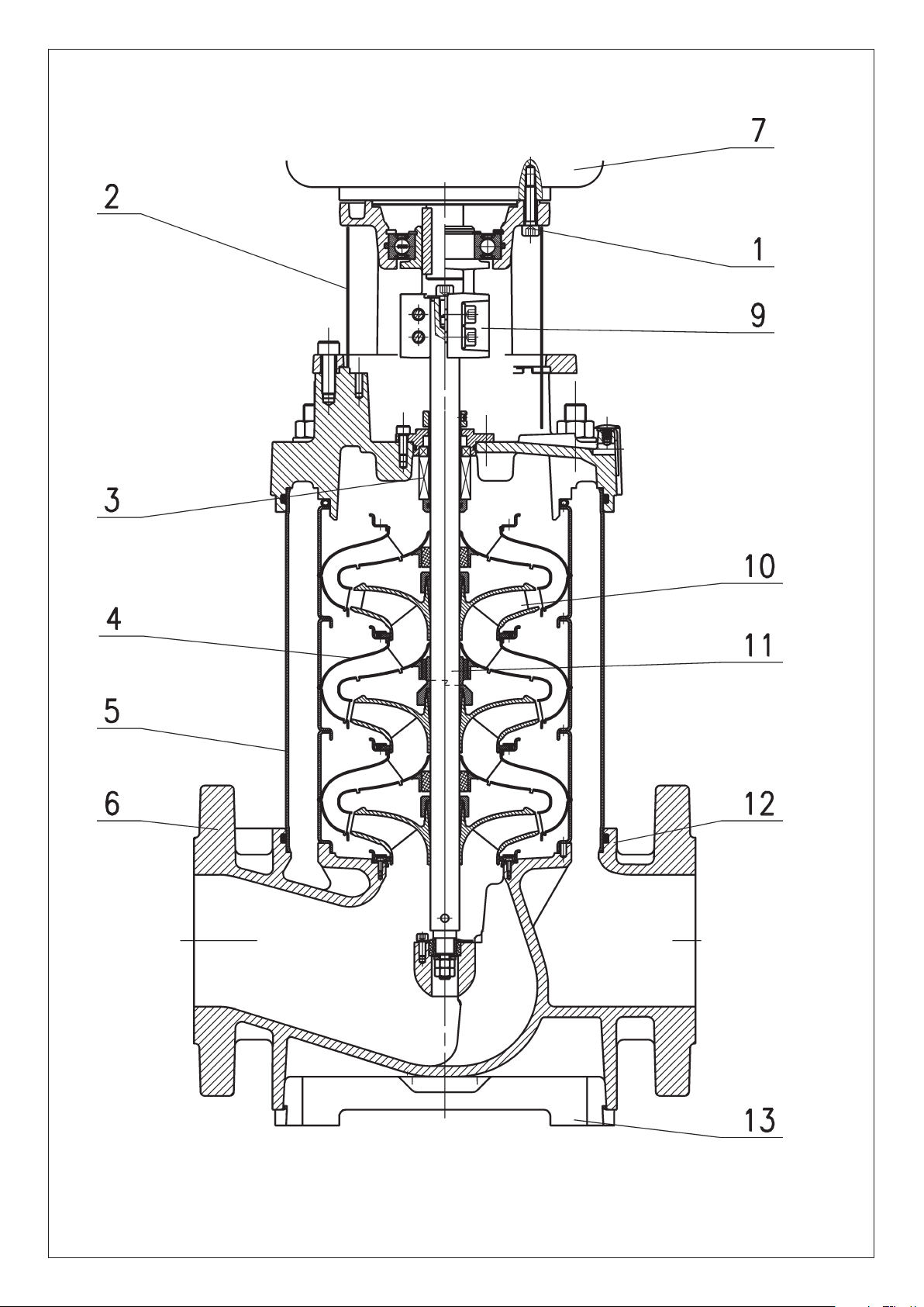
Fig. 1
MVI 70...
/MVI 95...
Page 4
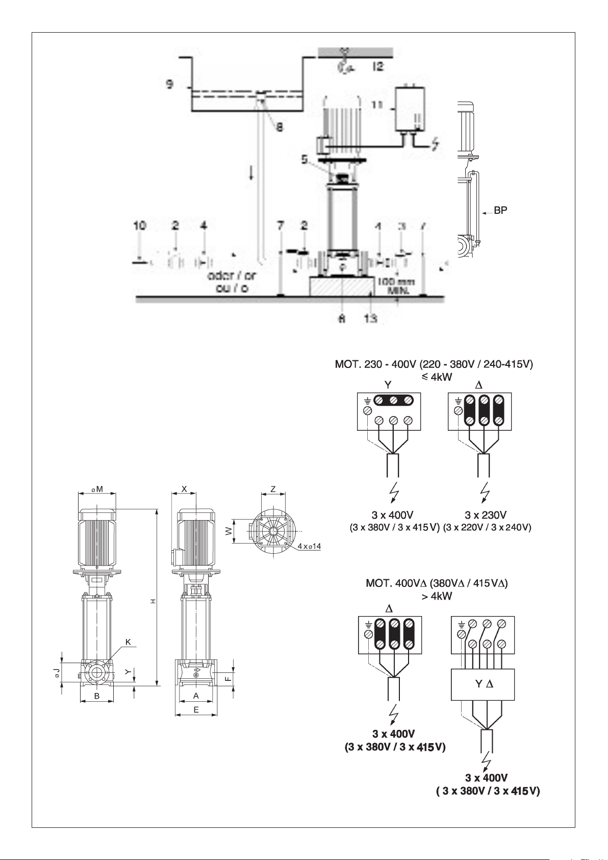
Fig. 3
Fig. 2
Fig. 4
Page 5

D
GB
EC declaration of conformity . . . . . . . . . . . . . . . . . . . . . . . . . . . . . 2-3
1. General Information . . . . . . . . . . . . . . . . . . . . . . . . . . . . . . . . 9
2. Safety . . . . . . . . . . . . . . . . . . . . . . . . . . . . . . . . . . . . . . . . . . . 10
3. Transport and interim storage . . . . . . . . . . . . . . . . . . . . . . . . . 10
4. Product and accessory description . . . . . . . . . . . . . . . . . . . . . 10
5. Assembly / Installation . . . . . . . . . . . . . . . . . . . . . . . . . . . . . . 11
6. Commissioning . . . . . . . . . . . . . . . . . . . . . . . . . . . . . . . . . . . . 11
7. Maintenance . . . . . . . . . . . . . . . . . . . . . . . . . . . . . . . . . . . . . . 12
8. Problems, Causes and Solutions . . . . . . . . . . . . . . . . . . . . . . 13
F
Déclaration de conformité CE . . . . . . . . . . . . . . . . . . . . . . . . . . . . 2-3
1. Généralités . . . . . . . . . . . . . . . . . . . . . . . . . . . . . . . . . . . . . . . 14
2. Sécurité . . . . . . . . . . . . . . . . . . . . . . . . . . . . . . . . . . . . . . . . . 15
3. Transport et stockage avant utilisation . . . . . . . . . . . . . . . . . . 15
4. Description du produit et de ses accessoires . . . . . . . . . . . . . 15
5. Installation / Montage . . . . . . . . . . . . . . . . . . . . . . . . . . . . . . . 16
6. Mise en service . . . . . . . . . . . . . . . . . . . . . . . . . . . . . . . . . . . . 16
7. Entretien . . . . . . . . . . . . . . . . . . . . . . . . . . . . . . . . . . . . . . . . . 17
8. Pannes, causes et remèdes . . . . . . . . . . . . . . . . . . . . . . . . . . 18
I
Dichiarazione di conformità CE . . . . . . . . . . . . . . . . . . . . . . . . . . . 2-3
1. Introduzione . . . . . . . . . . . . . . . . . . . . . . . . . . . . . . . . . . . . . . 19
2. Sicurezza . . . . . . . . . . . . . . . . . . . . . . . . . . . . . . . . . . . . . . . . 20
3. Trasporto e magazzinaggio . . . . . . . . . . . . . . . . . . . . . . . . . . . 20
4. Descrizione del prodotto e degli accessori . . . . . . . . . . . . . . . 20
5. Istruzioni di montaggio e installazione . . . . . . . . . . . . . . . . . . . 21
6. Messa in esercizio . . . . . . . . . . . . . . . . . . . . . . . . . . . . . . . . . 21
7. Manutenzione . . . . . . . . . . . . . . . . . . . . . . . . . . . . . . . . . . . . . 22
8. Risoluzione di problemi . . . . . . . . . . . . . . . . . . . . . . . . . . . . . . 23
CE-Konformitätserklärung . . . . . . . . . . . . . . . . . . . . . . . . . . . . . . 2-3
1. Allgemeines . . . . . . . . . . . . . . . . . . . . . . . . . . . . . . . . . . . . . . 4
2. Sicherheit . . . . . . . . . . . . . . . . . . . . . . . . . . . . . . . . . . . . . . . . 5
3. Transport und Zwischenlagerung . . . . . . . . . . . . . . . . . . . . . . 5
4. Beschreibung von Erzeugnis und Zubehör . . . . . . . . . . . . . . . 5
5. Aufstellung / Einbau . . . . . . . . . . . . . . . . . . . . . . . . . . . . . . . . 6
6. Inbetriebnahme . . . . . . . . . . . . . . . . . . . . . . . . . . . . . . . . . . . 6
7. Wartung . . . . . . . . . . . . . . . . . . . . . . . . . . . . . . . . . . . . . . . . . 7
8. Störungen, Ursachen und Beseitigung . . . . . . . . . . . . . . . . . . 8
1
Page 6

D EG - Konformitätserklärung
GB EC – Declaration of conformity
F Déclaration de conformité CEE
Hiermit erklären wir, dass die Bauarten der Baureihe :
Herewith, we declare that this product:
Par le présent, nous déclarons que cet agrégat :
MVI 16
MVI 32
MVI 52
MVI 70
MVI 95
in der gelieferten Ausführung folgenden einschlägigen Bestimmungen entspricht:
in its delivered state comply with the following relevant provisions:
est conforme aux dispositions suivants dont il relève:
EG-Maschinenrichtlinie 98/37/EG
EC-Machinery directive
Directives CEE relatives aux machines
Elektromagnetische Verträglichkeit - Richtlinie 89/336/EWG
Elektromagnetic compatability - directive
Compatibilité électromagnétique- directive
i.d.F/ as amended/ avec les amendements suivants:
91/263/EWG
92/31/EWG
93/68/EWG
Niederspannungsrichtlinie 73/23/EWG
Low voltage directive
Direction basse-tension
i.d.F/ as amended/ avec les amendements suivants :
93/68/EWG
Angewendete harmonisierte Normen, insbesondere:
Applied harmonized standards, in particular: EN 60034-1 Normes harmonisées, notamment:
EN 809
Dortmund, 11.04.2005
Quality Manager
Document: 2060375.1
Erwin Prieß
WILO AG
Nortkirchenstraße 100
44263 Dortmund
Page 7

NL
EG-verklaring van overeenstemming
Hiermede verklaren wij dat dit aggregaat in de
geleverde uitvoering voldoet aan de volgende
bepalingen:
EG-richtlijnen betreffende machines 98/37/EG
Elektromagnetische compatibiliteit
89/336/EEG als vervolg op 91/263/EEG,
92/31/EEG, 93/68/EEG
EG-laagspanningsrichtlijn 73/23/EEG als
vervolg op 93/68/EEG
Gebruikte geharmoniseerde normen, in het
bijzonder:
P
Declaração de Conformidade CE
Pela presente, declaramos que esta unidade
no seu estado original, está conforme os
seguintes requisitos:
Directivas CEE relativas a máquinas 98/37/CE
Compatibilidade electromagnética 89/336/CEE
com os aditamentos seguintes 91/263/CEE,
92/31/CEE, 93/68/CEE
Directiva de baixa voltagem 73/23/CEE com
os aditamentos seguintes 93/68/CEE
Normas harmonizadas aplicadas, especialmente:
FI
CE-standardinmukaisuusseloste
Ilmoitamme täten, että tämä laite vastaa
seuraavia asiaankuuluvia määräyksiä:
EU–konedirektiivit: 98/37/EG
Sähkömagneettinen soveltuvuus 89/336/EWG
seuraavin täsmennyksin 91/263/EWG
92/31/EWG, 93/68/EWG
Matalajännite direktiivit: 73/23/EWG seuraavin
täsmennyksin 93/68/EWG
Käytetyt yhteensovitetut standardit, erityisesti:
CZ
Prohlášení o shodě EU
Prohlašujeme tímto, že tento agregát
v dodaném provedení odpovídá následujícím
příslušným ustanovením:
Směrnicím EU–strojní zařízení 98/37/EG
Směrnicím EU–EMV 89/336/EWG ve sledu
91/263/EWG, 92/31/EWG, 93/68/EWG
Směrnicím EU–nízké napětí 73/23/EWG ve
sledu 93/68/EWG
Použité harmonizační normy, zejména:
∆ήλωση προσαρµογής στις προδιαγραφές
GR
της Ε.Ε. (Ευρωπαϊκής Ένωσης)
∆ηλώνουµε ότι το προϊόν αυτό σ’ αυτή την
κατάσταση παράδοσης ικανοποιεί τις
ακόλουθες διατάξεις :
Οδηγίες EG σχετικά µε µηχανήµατα 98/37/EG
Ηλεκτροµαγνητική συµβατότητα EG-
89/336/EWG όπως τροποποιήθηκε
91/263/EWG 92/31/EWG, 93/68/EWG
Οδηγία χαµηλής τάσης EG–73/23/EWG όπως
τροποποιήθηκε 93/68/EWG
Εναρµονισµένα χρησιµοποιούµενα πρότυπα,
ιδιαίτερα:
1)
1)
Erwin Prieß
Quality Manager
I
Dichiarazione di conformità CE
Con la presente si dichiara che i presenti
prodotti sono conformi alle seguenti
disposizioni e direttive rilevanti:
Direttiva macchine 98/37/CE
Compatibilità elettromagnetica 89/336/CEE e
seguenti modifiche 91/263/CEE, 92/31/CEE,
93/68/CEE
Direttiva bassa tensione 73/23/CEE e
seguenti modifiche 93/68/CEE
Norme armonizzate applicate, in particolare: 1)
S
CE- försäkran
Härmed förklarar vi att denna maskin i
levererat utförande motsvarar följande
tillämpliga bestämmelser:
EG–Maskindirektiv 98/37/EG
EG–Elektromagnetisk kompatibilitet – riktlinje
89/336/EWG med följande ändringar
91/263/EWG, 92/31/EWG, 93/68/EWG
EG–Lågspänningsdirektiv 73/23/EWG med
följande ändringar 93/68/EWG
1)
Tillämpade harmoniserade normer, i synnerhet: 1)
DK
EF-overensstemmelseserklæring
Vi erklærer hermed, at denne enhed ved
levering overholder følgende relevante
bestemmelser:
EU–maskindirektiver 98/37/EG
Elektromagnetisk kompatibilitet: 89/336/EWG,
følgende 91/263/EWG, 92/31/EWG,
93/68/EWG
Lavvolts-direktiv 73/23/EWG følgende
1)
1)
93/68/EWG
Anvendte harmoniserede standarder, særligt:
PL
Deklaracja Zgodności CE
Niniejszym deklarujemy z pełną
odpowiedzialnoscią że dostarczony wyrób jest
zgdony z następującymi dokumentami:
EC–dyrektywa dla przemysłu maszynowego
98/37/EG
Odpowiedniość elektromagnetyczna
89/336/EWG ze zmianą 91/263/EWG,
92/31/EWG, 93/68/EWG
Normie niskich napięć 73/23/EWG ze zmianą
93/68/EWG
Wyroby są zgodne ze szczegółowymi normami
zharmonizowanymi:
TR
EC Uygunluk Teyid Belgesi
Bu cihazın teslim edildiği şekliyle aşağıdaki
standartlara uygun olduğunu teyid ederiz:
AB-Makina Standartları 98/37/EG
Elektromanyetik Uyumluluk 89/336/EWG ve
takip eden, 91/263/EWG, 92/31/EWG,
93/68/EWG
Alçak gerilim direktifi 73/23/EWG ve takip
eden, 93/68/EWG
Kısmen kullanılan standartlar:
1)
1)
E
Declaración de conformidad CE
Por la presente declaramos la conformidad
del producto en su estado de suministro con
las disposiciones pertinentes siguientes:
Directiva sobre máquinas 98/37/CE
Directiva sobre compatibilidad
electromagnética 89/336/CEE modificada por
91/263/CEE, 92/31/CEE, 93/68/CEE
Directiva sobre equipos de baja tensión
73/23/CEE modificada por 93/68/CEE
Normas armonizadas adoptadas, especialmente:
N
EU-Overensstemmelseserklæring
Vi erklærer hermed at denne enheten i
utførelse som levert er i overensstemmelse
med følgende relevante bestemmelser:
EG–Maskindirektiv 98/37/EG
EG–EMV–Elektromagnetisk kompatibilitet
89/336/EWG med senere tilføyelser:
91/263/EWG, 92/31/EWG, 93/68/EWG
EG–Lavspenningsdirektiv 73/23/EWG med
senere tilføyelser: 93/68/EWG
Anvendte harmoniserte standarder, særlig:
H
EK. Azonossági nyilatkozat
Ezennel kijelentjük,hogy az berendezés az
alábbiaknak megfelel:
EK Irányelvek gépekhez: 98/37/EG
Elektromágneses zavarás/türés: 89/336/EWG
és az azt kiváltó 91/263/EWG, 92/31/EWG,
93/68/EWG
Kisfeszültségü berendezések irány-Elve:
73/23/EWG és az azt kiváltó 93/68/EWG
1)
Felhasznált harmonizált szabványok, különösen:
Деклация о соответствии
RUS
1)
1)
1)
Европейским нормам
Настоящим документом заявляем, что
данный агрегат в его объеме поставки
соответствует следующим нормативным
документам:
Директивы EC в отношении машин
98/37/EG
Электромагнитная устойчивость
89/336/EWG с поправками 91/263/EWG,
92/31/EWG, 93/68/EWG
Директивы по низковольтному напряжению
73/23/EWG с поправками 93/68/EWG
Используемые согласованные стандарты и
нормы, в частности :
1)
EN 809,
1)
EN 60034-1.
WILO AG
Nortkirchenstraße 100
44263 Dortmund
Page 8

ENGLISH
9
1 General Information
Installation and commissioning only by qualified personnel
1
.1 Uses
The pump is suitable for hot and cold water and other fluids free from
mineral oil and without abrasives or long-fibred substances. The main
areas of use are in water supply installations, as a booster pump, as a
boiler feeder pump, in industrial circulation systems, in process technology, in cooling water systems, in fire extinguishers and in washing
and sprinkler installations.
1.2 Product data
1.2.1 Connection and electrical data (Table 1)
Pumping medium allowed
Permissible media temperature
Maximum ambient temperature
Maximum permissible working pressure: at the inlet (inlet pressure see paragraph 5.3)
at the outlet, for a 2 pole motor
at the outlet, for a 2 pole motor
Mains voltages DM: for P2 ≤ 4 kW:
for P2 ≥ 5.5 kW:
Standard motor for P2 ≤ 5.5 kW:
for P2 ≥ 7.5 kW:
Speed 2 pole version
4 pole version
Mains fuse protection
Insulation class
System of protection
Drinking water in acc. with Drinking Water Order
Heating water / service water
Condensate
Water/glycol mixture1)
Other liquid media2)
-15
°C to +120 °C
(Follow catalogue instructions)
+40 °C
16/10 bar
16/25 bar
16/16 bar
3 ~ 230/400 V ±
10 %, 50 Hz
3 ~ 400 V ± 10 %, 50 Hz
V 18 standard motor
V 1 standard motor
2900 RPM
1450 RPM
see motor rating plate
F
IP 55
better protective systems available
1
) When using a water-glycol mixture containing up to 40% glycol (or media with a viscosity different to that of pure water, the flow data for the pump must be adjusted accord-
ing to the higher viscosity of the flow media, regardless of the percentage of the viscous matter. Only use branded goods with corrosion protection-inhibitors, follow manufacturer’s instructions.
2
) If other and also aggressive chemical fluids are to be pumped, be sure to follow catalogue instructions and first obtain the approval of WILO.
Principal dimensions and connection dimensions (Table 2, see also Fig. 3):
When ordering spare parts, please give all the information on the pump/motor rating plate.
Types PN16 version PN25 version
A B Y W Z E F J K A B Y W Z E F J K
MVI mm mm
1602 è 1614 DN50 194
252 20 215 130 300 90 125 4x18 194 252 20 215 130 300 90 125 4x18
3202 è 3216 DN65 235
235 35 195 195 320 105 145 4x18 260 260 35 220 220 320 120 145 8x18
5202 è 5212 DN80 260
260 30 220 220 320 105 160 8x18 260 260 30 220 220 320 105 160 8x18
7001 è 7007 DN100 261
350 45 280 199 380 140 180 8x19 261 350 45 280 199 380 140 190 8x23
9501 è 9506 DN100 261
350 45 280 199 380 140 180 8x19 261 350 45 280 199 380 140 190 8x23
Page 9

ENGLISH
1.2.2 Type ke
Design MVI
(Multistage, vertic.
Special steel-(Inox-)
centrifugal pump)
Flow rate [m3/h]
(2-pole/ 50 Hz)
Number of
impellers in row
Material quality:
Hydraulic / Base
1 R unoccupied
2 R 1.4404 / 1.4408 (AISI 316 L)
3 R 1.4301 / GG25 (coated)
maximum permissible working
pressure [bar] PN 16 or PN 25
E
PDM seals (KTW/WRAS)
V
ITON seals
Main voltage 3 ~ 400 V
50 Hz or 60 Hz frequency
2- or 4-pole motor
Manufacturer’s key
y
MVI 16 08 3 / 16 / E / 3 - 400 - 50 - 2 / XX / X
3 ~ 230 V
2 Safety
These instructions contain important information which must be
followed when installing and operating the pump. These operating
instructions must therefore be read before assembly and commissioning by the installer and the responsible operator. Both the general
safety instructions in the “Safety precautions” section and those in
subsequent sections indicated by danger symbols should be carefully
observed.
2.1 Danger symbols used in these operating instructions
Safety precautions in these operating instructions which, if not
followed, could cause personal injury are indicated by the symbol:
when warning of electrical voltage with
The following symbol is used to indicate that by ignoring the relevant
safety instructions, damage could be caused to the pump/machinery
and its functions:
WARNING!
2.2 S
taff training
The personnel installing the pump must have the appropriate qualifications for this work.
2.3 Risks incurred by failure to comply with the safety precautions
Failure to comply with the safety precautions could result in personal
injury or damage to the pump or installation. Failure to comply with the
safety precautions could also invalidate any claim for damages.
In particular, failure to comply with these safety precautions could give
rise, for example, to the following risks:
– Failure of important pump or machinery functions,
– Personal injury due to electrical, mechanical and bacteriological
causes.
– Damage to property.
2.4 Safety precautions for the operator
Existing regulations for the prevention of accidents must be followed.
Dangers caused by electrical energy are to be excluded. Directives
issued by the VDE [German Association of Electrical Engineers] and
the local electricity supply companies are to be observed.
2.5 Safety information for inspection and assembly
The operator is responsible for ensuring that inspection and assembly
are carried out by authorised and qualified personnel who have
studied the operating instructions closely.
Work on the pump/machinery should only be carried out when the
machine has been brought to a standstill.
2.6 Unauthorized modification and manufacture of spare parts
Changes to the pump/machinery may only be made in agreement with
the manufacturer. The use of original spare parts and accessories
authorised by the manufacturer will ensure safety. The use of any other
parts may invalidate claims invoking the liability of the manufacturer for
any consequences.
2.7 Improper use
The operating safety of the pump or installation supplied can only be
guaranteed if it is used in accordance with paragraph 1 of the operating instructions. The limiting values given in the catalogue or data
sheet must neither be exceeded nor allowed to fall below those specified.
3
Transport and storage
WARNING!
damage. The pump unit is to be transported with the shaft horizontal.
When storing, ensure that the pump unit cannot overturn as a result of
top-heaviness.
During transport and in storage the pump must be
protected against moisture, frost and mechanical
4 Product and accessory description
4.1 The pumps
The pump is a multistage (1–16 stages) normal suction vertical high
pressure centrifugal pump with an in-line design, i.e. the inlet and outlet pressure glands are in a line. The pump is available in 2 pressure
versions, PN 16 and PN 25 with integrally cast circular flanges.
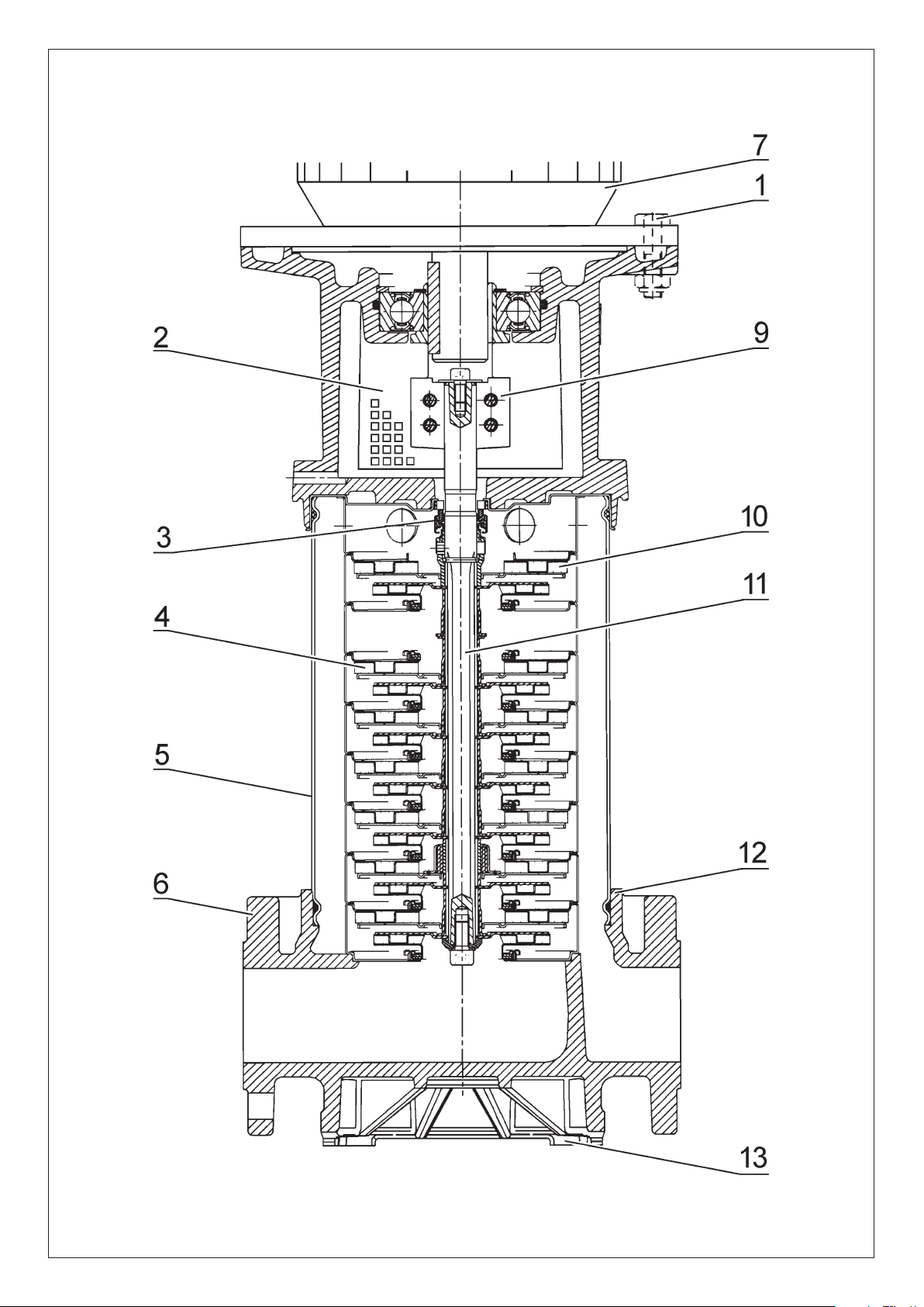
The pump (Fig. 1) stands on a grey cast iron pump footplate which
serves as a fixing base (13). The stage casings (4) are in a multiple
modular construction. The impellers (10) are fitted on a single shaft
(11). The pressure casing (5) guarantees a fail-safe seal.
All parts that come into contact with the medium, such as stage housings, impellers and pressure casings are made of chromium nickel
steel, the pump footplate (Pos. 12) with flanges (Pos. 6) of coated
GG 25 (up to 85 °C) or of chromium nickel steel (on request). The shaft
hole through the pump casing is sealed with an axial face seal (3).
MVI32C, MVI52C, MVI70 and MVI95 are equipped
with a cartridge system in order to ease standard
mechanical seal replacement without disassembling the hydraulic parts.
“Spacer” feature allows not to disassemble motor on MVI32C,
MVI52C, MVI70 and MVI95 when removing mechanical seal cartridge.
The pump and motor shafts are linked together by a clutch (9). All
parts of the drinking water version (version E) which are in contact with
the fluid have been cleared by KTW and WRAS and are therefore suitable for use with drinking water.
The speed of the pump can be controlled when connected to a
frequency converter (see paragraph 5.3).
4.2 Products delivered
– high pressure centrifugal pump
10
Page 10
ENGLISH
– Check that the mains current and voltage comply with the data on
the rating plate.
– Pump/installation must be earthed in compliance with regulations.
– All motors must be fitted with a motor safety switch by the customer
to prevent the motor from overheating.
Adjusting the motor safety switch:
Direct starting current: Adjust to nominal current of the motor in
accordance with the data on the motor rating plate.
Y
-∆
-start: If the motor safety switch is connected as a star or triangu-
lar safety circuit combination at the supply line it can be adjusted in the
same way units operating on direct starting current. If the motor safety
switch is connected to the motor supply line in phase (U1/V1/W1 or
U2/V2/W2), then the motor safety switch should be adjusted to the
value of 0.58 of the nominal motor current.
– The mains cable can be inserted to the left or the right of the termi-
nal box. Open the appropriate hole by removing the moulded cover,
unscrew the PG connector and push the cable through the PG
connector.
– The supply cable must be protected against the effects of heat and
vibrations which may come from the motor or the pump.
– When using the pump in machinery where the water temperature
exceeds 90 °C, a connecting pipe with corresponding heat
resistance must be used.
– Connections to the mains must be carried out in accordance with
the plan of terminal connections for rotary or alternating current in
the terminal box of the pump (Fig. 4).
– The terminal box can be better positioned by rotating the motor
through steps of 90°. To this end the connecting screws (Fig. 1,
Pos. 1) of the lantern (Fig. 1, Pos. 8) and motor flange are to be
loosened.
In the case of internal connecting screws the clutch guard (Fig. 1,
Pos. 2) is to be removed beforehand. When assembling the clutch
guard, do not forget to tighten the safety screw.
5.3 Operation with frequency converter
The speed of the pump can be controlled when connected to a
frequency converter.
See Installation and Operating Instructions of the frequency converter
for connection and operation.
The frequency converter may not generate a speed due to increased
voltage greater than 2500 V/µs and voltage peaks û > 1000 V, as
otherwise the motor coil will be destroyed. If such speeds due to the
increased voltage are possible, an LC filter (motor filter) should be
installed between the frequency converter and the motor.
6 Commissioning
In order to protect the axial face seal, the pump
must not run dry.
– Close both isolating valves and open the vent screw (Fig. 2, 5) by
one and a half or two turns.
– Slowly open the isolating valve (Fig. 2, 2) at the inlet until the air has
escaped from the vent screw and the fluid to be pumped comes
out. The escaping air will be clearly heard hissing. Tighten the vent
screw.
– Slowly open the isolating valve at the outlet (Fig. 2, 3). The mano-
meter installed at the outlet should be checked for any possible
pressure instabilities, indicated by a flickering manometer pointer. If
the pressure is unstable, allow more air to escape.
When the temperature of the liquid being pumped is high
and the system is pressurised, any flow escaping from the
vent screw can cause scalding and injuries. The vent
screw should therefore be loosen only slightly.
– When used for the first time, if it is to be used to pump drinking
water the system must be flushed through, so that any dirty water
present will not contaminate the drinking water supply.
– Checking the direction of rotation (only for rotary current motors):
Check that the pump rotates in the same direction indicated by the
arrow on the pump casing by switching on for a short time. If this is
not the case, interchange 2 phases in the terminal box.
WARNING!
– Installation and operating instructions
4.3 Accessories
see catalogue or data sheet
5 Assembly/Installation
– See the rating plate of the pump and the rating plate of the motor
5.1 Assembly
WARNING!
work has been completed. Dirt will damage the pump.
– Install the pump in a dry place free of frost.
– Install in a horizontal and flat position. If the pump is positioned on
an incline the bearing will wear more quickly.
– Install the pump in an easily accessible place to facilitate inspection
and disassembly. Always install the pump exactly perpendicular on a
sufficiently heavy concrete base (Fig. 2, 3). Fit a vibration absorber
between the base and the floor.
– Dimensions for installation and connections are given in Paragraph
1.2.1, Table 2 and in Fig. 3.
– In the case of heavy pumps fit a hook (Fig. 2, Pos. 12) or eye with a
suitable load-bearing capacity (total weight of pump: see catalogue/
data sheet) vertically above the pump, to which a hoist or similar
device can be attached when maintaining or repairing the pump.
Allow for a free size when completed of min. 200 mm.
– The arrow on the pump casing indicates the direction of flow.
– Fit the inlet and outlet pipes without stress. Install below expansion
joints of restricted length to absorb vibrations. The pipes must be
attached (Fig. 2, 7) in such a way that the pump does not bear the
weight of the pipes.
– Isolation mechanisms (Fig. 2, 2 & 3) must in principle be installed in
front of and behind the pump to avoid having to empty and refill the
whole installation when inspecting or changing the pump.
– To avoid pressure loss it is recommended that you choose as short
an inlet pipe as possible, choose a nominal width for the suction
pipe which is larger by a nominal width than the pump connection
and avoid constrictions caused by bends and valves.
– A backflow preventer (Fig. 2, 4) should be fitted in the outlet pipe.
– For differential pressures > 6 bar the backflow preventer (Fig. 2,
Pos. 4) is to be fitted in the suction pipe. It is not required at the
outlet.
– The axial face seal should be protected against dry running. An inlet
pressure gauge or level gauge should be installed by the customer.
– If the pump is to be connected indirectly via a reservoir, a suction
strainer (Fig. 2, 8) must be provided in the inlet pipe by the customer
to prevent coarse impurities entering the pump.
– With limited nominal pressure PN, ensure that this pressure is pro-
duced from the inlet pressure and the zero flow level:
– For gaseous or hot pumping media a bypass pipe is to be fitted to
the pump (Fig. 2, Pos. BP), (accessory).
5.2 Electrical connection
Assembly should only take place once all welding
and soldering work and the rinsing of the pipe net-
P
≤ PN - P
Inlet
Electrical connection should be made by a qualified electrician. Current national regulations must be observed (e.g.
VDE regulations in Germany).
max pump
11
Page 11

ENGLISH
For pumps with a star or triangular circuit starting current, the
connections of two coils must be interchanged, e.g. U1 with V1 and
U2 with V2.
– If the fluid temperature is too high, steam may form which may
damage the pump. The pump must therefore not run with the valve
closed for longer than 10 minutes when pumping cold water or for
longer than five minutes when pumping fluid where > 60
°C.
We recommend that the flow rate does not drop to below 10 % of
the nominal flow rate so as to avoid a build up of steam in the pump.
– If there is a build up of steam, this should be allowed to escape by
carefully opening the vent screw.
Both pump and motor can reach operating temperatures
> 100 °C. Therefore exercise caution when touching the
pump.
7 Maintenance
Before carrying out any maintenance work, switch off the
pump and ensure that it cannot be switched on again by
unauthorised people. Never carry out work on a running
pump.
– During the running-in period, there may be some dripping from the
axial face seal. In the event of a serious leak as a result of heavy
wear have the mechanical seal replaced by a specialist.
– Increased bearing noise and unusual vibrations indicate a worn
bearing. In this case, have the bearing replaced by a specialist.
– If the pump is exposed to frost, the pump and pipework must be
emptied in the cold season. Close the isolating valve and open the
drain valve (Fig. 2, 6) and the vent screw (Fig. 2, 5) of the pump.
The isolating valve must be closed before the drain valve is
opened.
– If placed in a frost-free location, the pump does not have to be emptied, even if it is out of service for a long period.
Type
< 22 kW
22 kW
✔
✔ ✔
✔ ✔
✔ ✔
✔
✔
✔
✔
30 kW 37 kW 45 kW
MVI 16
MVI 32
MVI 52
MVI 70
MVI 95
On pumps equipped with greaser under bearing box (table below), see
greasing instructions written on sticker put on it:
For pumps equipped with coupling bush, check it
before reassembling.
12
Page 12

8 Problems, Causes and Solutions
ENGLISH
Problem
Pump does not run
Pump runs but does not pump
Pump does not pump evenly
Pump vibrates and is noisy
Motor overheats
motor cut-out activates
Cause
no power
motor safety switch activated
Incorrect direction of rotation
pipe or pump components blocked by
foreign body
air in inlet pipe
inlet pipe too narrow
valve not sufficiently open
air in the pump
foreign body in the pump
pump not properly fixed to the base
bearing damaged
one phase interrupted
pump sluggish:
foreign body
Solutions
check fuses, cables and connections
Eliminate motor overload
check direction of rotation and correct if necessary
Check and clean pipe and pump
Seal inlet pipe
fit a larger inlet pipe
open valve
bleed the pump
remove foreign body
tighten anchor bolts
consult customer services
check fuses, cables and connections
clean pump
bearing damaged
ambient temperature too high
If the fault cannot be remedied, please contact your plumbing and heating specialist or your nearest WILO customer services or
representative.
Subject to technical alterations!
have pump repaired by customer services
provide cooling
13
Page 13

WILO AG
Nortkirchenstraße 100
44263 Dortmund
Germany
T +49 231 4102-0
F +49 231 4102-7363
www.wilo.com
Azerbaijan
370141 Baku
T +994 50 2100890
F +994 12 4975253
info@wilo.az
Bosnia and Herzegovina
71000 Sarajevo
T +387 33 714511
F +387 33 714510
anton.mrak@wilo.si
Croatia
10000 Zagreb
T +385 1 3680474
F +385 1 3680476
rino.kerekovic@wilo.hr
Georgia
38007 Tbilisi
T/F +995 32 536459
info@wilo.ge
Macedonia
1000 Skopje
T/F +389 2122058
valerij.vojneski@wilo.com.mk
Moldova
2012 Chisinau
T/F +373 22 223501
sergiu.zagurean@wilo.md
Tajikistan
734025 Dushanbe
T +992 372 316275
info@wilo.tj
Uzbekistan
700029 Taschkent
T/F +998 71 1206774
wilo.uz@online.ru
März 2005
Wilo – International (Subsidiaries)
Wilo – International (Representation offices)
Austria
WILO Handelsges. m.b.H.
1230 Wien
T +43 1 25062-0
F +43 1 25062-15
office@wilo.at
Belarus
WILO Bel OOO
220035 Minsk
T +375 17 2503383
wilobel@mail.ru
Belgium
WILO NV/SA
1083 Ganshoren
T +32 2 4823333
F +32 2 4823330
info@wilo.be
Bulgaria
WILO Bulgaria EOOD
1125 Sofia
T +359 2 9701970
F +359 2 9701979
info@wilo.bg
Canada
WILO Canada Inc.
Calgary, Alberta T2A5L4
T +1 403 2769456
F +1 403 2779456
blowe@wilo-na.com
China
WILO SALMSON (Beijing)
Pumps System Ltd.
101300 Beijing
T +86 10 804939700
F +86 10 80493788
wilobj@wilo.com.cn
Czech Republic
WILO Praha s.r.o.
25101 Cestlice
T +420 234 098 711
F +420 234 098 710
info@wilo.cz
Denmark
WILO Danmark A/S
2690 Karlslunde
T +45 70 253312
F +45 70 253316
wilo@wilo.dk
Finland
WILO Finland OY
02320 Espoo
T +358 9 26065222
F +358 9 26065220
wilo@wilo.fi
France
WILO S.A.S.
78310 Coignières
T +33 1 30050930
F +33 1 34614959
wilo@wilo.fr
Great Britain
WILO SALMSON Pumps Ltd.
DE14 2WJ Burton-on-Trent
T +44 1283 523000
F +44 1283 523099
sales@wilo.co.uk
Greece
WILO Hellas AG
14569 Anixi (Attika)
T +30 10 6248300
F +30 10 6248360
wilo.info@wilo.gr
Hungary
WILO Magyarország Kft
1144 Budapest XIV
T +36 1 46770-70 Sales Dep.
46770-80 Tech. Serv.
F +36 1 4677089
wilo@wilo.hu
Ireland
WILO Engineering Ltd.
Limerick
T +353 61 227566
F +353 61 229017
sales@wilo.ie
Italy
WILO Italia s.r.l.
20068 Peschiera Borromeo
(Milano)
T +39 02 5538351
F +39 02 55303374
wilo.italia@wilo.it
Kazakhstan
TOO WILO Central Asia
480100 Almaty
T +7 3272 507333
F +7 3272 507332
info@wilo.kz
Korea
WILO Industries Ltd.
137-818 Seoul
T +82 2 34716600
F +82 2 34710232
wilo@wilo.co.kr
Latvia
WILO Baltic SIA
1019 Riga
T +371 7 145229
F +371 7 145566
mail@wilo.lv
Lebanon
WILO SALMSON
Lebanon s.a.r.l.
12022030 El Metn
T +961 4 722280
F +961 4 722285
wsl@cyberia.net.lb
Lithuania
UAB WILO Lietuva
03202 Vilnius
T +370 2 236495
F +370 2 236495
mail@wilo.lt
The Netherlands
WILO Nederland b.v.
1948 RC Beverwijk
T +31 251 220844
F +31 251 225168
wilo@wilo.nl
Norway
WILO Norge A/S
0901 Oslo
T +47 22 804570
F +47 22 804590
wilo@wilo.no
Poland
WILO Polska Sp. z.o.o.
05-090 Raszyn k/Warszawy
T +48 22 7201111
F +48 22 7200526
wilo@wilo.pl
Portugal
Bombas Wilo-Salmson
Portugal
4050-040 Porto
T +351 22 2080350
F +351 22 2001469
bombas@wilo-salmson.pt
Romania
WILO Romania s.r.l.
7000 Bucuresti
T +40 21 4600612
F +40 21 4600743
wilo@wilo.ro
Russia
WILO Rus o.o.o.
123592 Moskau
T +7 095 7810690
F +7 095 7810691
wilo@orc.ru
Serbia & Montenegro
WILO Beograd d.o.o.
11000 Beograd
T +381 11 765871
F +381 11 3292306
dragan.simonovic@wilo.co.yu
Slovakia
WILO Slovakia s.r.o.
82008 Bratislava 28
T +421 2 45520122
F +421 2 45246471
wilo@wilo.sk
Slovenia
WILO Adriatic d.o.o.
1000 Ljubljana
T +386 1 5838130
F +386 1 5838138
detlef.schilla@wilo.si
Spain
WILO Ibérica S.A.
28806 Alcalá de Henares
(Madrid)
T +34 91 8797100
F +34 91 8797101
wilo.iberica@wilo.es
Sweden
WILO Sverige AB
35033 Växjö
T +46 470 727600
F +46 470 727644
wilo@wilo.se
Switzerland
EMB Pumpen AG
4310 Rheinfelden
T +41 61 8368020
F +41 61 8368021
info@emb-pumpen.ch
Turkey
WILO Pompa Sistemleri
San. ve Tic. A.S¸.
34530 Istanbul
T +90 216 6610211
F +90 216 6610214
wilo@wilo.com.tr
Ukraina
WILO Ukraina t.o.w.
01033 Kiew
T +38 044 2011870
F +38 044 2011877
wilo@wilo.ua
USA
WILO USA LLC
Calgary, Alberta T2A5L4
T +1 403 2769456
F +1 403 2779456
blowe@wilo-na.com
Page 14

WILO AG
Nortkirchenstraße 100
44263 Dortmund
Germany
T 0231 4102-0
F 0231 4102-7363
wilo@wilo.de
www.wilo.de
G1 Nord
WILO AG
Ver triebsbüro Hamburg
Sinstorfer Kirchweg 74–92
21077 Hamburg
T 040 5559490
F 040 55594949
G2 Ost
WILO AG
Ver triebsbüro Berlin
Juliusstraße 52–53
12051 Berlin-Neukölln
T 030 6289370
F 030 62893770
G3 Sachsen/Thüringen
WILO AG
Ver triebsbüro Dresden
Frankenring 8
01723 Kesselsdorf
T 035204 7050
F 035204 70570
G4 Südost
WILO AG
Ver triebsbüro München
Landshuter Straße 20
85716 Unterschleißheim
T 089 4200090
F 089 42000944
G5 Südwest
WILO AG
Ver triebsbüro Stuttgart
Hertichstraße 10
71229 Leonberg
T 07152 94710
F 07152 947141
G6 Rhein-Main
WILO AG
Ver triebsbüro Frankfurt
An den drei Hasen 31
61440 Oberursel/Ts.
T 06171 70460
F 06171 704665
G7 West
WILO AG
Ver triebsbüro Düsseldorf
Hans-Sachs-Straße 4
40721 Hilden
T 02103 90920
F 02103 909215
G8 Nordwest
WILO AG
Ver triebsbüro Hannover
Ahrensburger Straße 1
30659 Hannover-Lahe
T 0511 438840
F 0511 4388444
Zentrale Auftragsbearbeitung
für den Fachgroßhandel
WILO AG
Auftragsbearbeitung
Nortkirchenstraße 100
44263 Dortmund
T 0231 4102-0
F 0231 4102-7555
Wilo-Kompetenz-Team
–Antworten auf alle Fragen
rund um das Produkt,
Lieferzeiten, Versand,
Verkaufspreise
–Abwicklung Ihrer Aufträge
–Ersatzteilbestellungen – mit
24-Stunden-Lieferzeit
für alle gängigen
Ersatzteile
–Versand von
Informationsmaterial
T 01805 R•U•F•W•I•L•O*
7•8•3•9•4•5•6
F 0231 4102-7666
Werktags erreichbar
von 7–18 Uhr
Wilo-Kundendienst
WILO AG
Wilo-Service-Center
Nortkirchenstraße 100
44263 Dortmund
–Kundendienststeuerung
–Wartung und Inbetriebnahme
–Werksreparaturen
–Ersatzteilberatung
T 01805 W•I•L•O•K•D*
9•4•5•6•5•3
0231 4102-7900
F 0231 4102-7126
Werktags erreichbar von
7–17 Uhr, ansonsten
elektronische Bereitschaft mit
Rückruf-Garantie!
Wilo-International
Österreich
Zentrale Wien:
WILO Handelsgesellschaft mbH
Eitnergasse 13
1230 Wien
T +43 1 25062-0
F +43 1 25062-15
Ver triebsbüro Salzburg:
Gnigler Straße 56
5020 Salzburg
T +43 662 8716410
F +43 662 878470
Ver triebsbüro Oberösterreich:
Trattnachtalstraße 7
4710 Grieskirchen
T +43 7248 65051
F +43 7248 65054
Schweiz
EMB Pumpen AG
Gerstenweg 7
4310 Rheinfelden
T +41 61 8368020
F +41 61 8368021
Standorte weiterer
Tochtergesellschaften
Belarus, Belgien, Bulgarien, China,
Dänemark, Finnland, Frankreich,
Griechenland, Großbritannien,
Irland, Italien, Kanada,
Kasachstan, Korea, Libanon,
Litauen, Lettland, Niederlande,
Norwegen, Polen, Rumänien,
Russland, Schweden, Serbien &
Montenegro, Slowakei,
Slowenien, Spanien, Tschechien,
Türkei, Ukraine, Ungarn
Die Adressen finden Sie unter
www.wilo.de oder
www.wilo.com.
Stand März 2005
* 12 Cent pro Minute
Wilo-Vertriebsbüros
 Loading...