

Page 1
I
F
-
M
o
d
u
l
Wilo-Control
IF-Modul LON / IF-Modul Stratos LON
D Einbau- und Betriebsanleitung
GB Installation and operating instructions
/ www.wilo.com/automation
2 084 903-Ed.02 / 2011-05 Wilo
Page 2
nv1
nviRequest
SNVT_obj_request
nv2
nvoStatus
SNVT_obj_status
nv8
nvoFileDirectory
SNVT_address
Mandatory
Configuration
Optional
Node Object
Mandatory
Optional
nciMaxStsSendT scpt22
nciDevMajVer scpt165
nciDevMinVer scpt166
nciLocation scpt17
Sollwertobergrenze
(Hersteller- ,
Pumpen- und
Regelartspezifisch)
Tatsächlicher Sollwert [%]
STOP
X
100%
Pump Setpoint
nviPumpSetpoint
[%]
Sollwertuntergrenze
(Hersteller- ,
Pumpen- und
Regelartspezifisch)
X = ( Sollwertuntergrenze / Sollwertobergrenze ) * 100%
Fig.1a:
Fig.2:
Page 3
nv1
nviPumpSetpoint
SNVT_switch
nv2
nviPumpOpMode
SNVT_hvac_mode
nv3
nvoPumpCapacity
SNVT_lev_percent
nv4
nvoEffOpMode
SNVT_hvac_mode
nv5
nvoControlMode
SNVT_dev_c_mode
nv13
nvoPumpStatus
SNVT_dev_status
nv6
nviPumpOvdStop
SNVT_switch
nv7
nviOvdSpeed
SNVT_lev_percent
nv8
nviOvdPress
SNVT_press
nv10
nviRemotePress
SNVT_press
nv12
nviRemoteTemp
SNVT_temp_p
nv14
nvoPressure
SNVT_press
nv15
nvoFlow
SNVT_flow_p
nv16
nvoSpeed
SNVT_rpm
nv17
nvoPumpOverride
SNVT_switch
nv18
nvoRuntime
SNVT_time_hour
nv19
nvoPumpFault
SNVT_dev_fault
nv20
nvoMaintenance
SNVT_dev_maint
nv21
nvoFluidTemp
SNVT_temp_p
nv22
nvoPower
SNVT_power
nv23
nvoPowerKilo
SNVT_power_kilo
nv24
nvoEnergyConsum
SNVT_elec_kwh
Mandatory
Optional
Configuration
Pump Controller Object
Mandatory
Optiona l
nciRcvHrtBt scpt48
nciSndHrtBt scpt49
nciMinOutTm scpt52
nciControlMode scpt238
nciRemMinPress scpt239
nciRemMaxPress scpt240
nciRemMinTemp scpt243
nciRemMaxTemp scpt244
nciObjMajVer scpt167
nciObjMinVer scpt168
nroPumpChar scpt233
nciPressTemp ucpt
nciSetpPreset scpt213
nv38
nvoCurrentErrorM
SNVT_count
nv39
nvoCurrentErrorS
SNVT_count
nv40
nvoPumpStatusM
SNVT_dev_status
nv41
nvoPumpStatusS
SNVT_dev_status
nv42
nvoPumpType
SNVT_count
Fig.1b:
Fig.3a:
Page 4
I
F
-M
o
d
ul
n
u
n
g
A
t
t
e
n
t
ion
M
ai
n
s
V
ol
tage
L N SSM
e
g
g
n
!
a
lt
o
V
Mains
on
ti
en
tt
A
l
u
d
o
M
F
I
u
n
n
a
zsp
t
e
N
n
o
ti
p
O
g
n
tu
h
c
A
on
V
ng
i
0
t
u
t
3
2
h
en
t
c
t
A
1 -
A
Fig.3b:
Page 5
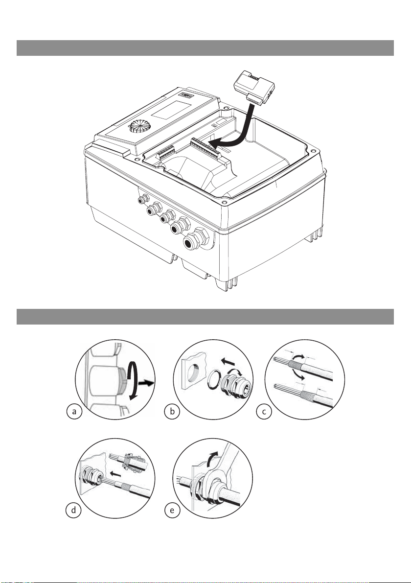
Fig.3c:
Fig.4a:
~15 mm
~15 mm
Page 6
~15 mm
~15 mm
Fig.4b:
Fig.4c:
~15 mm
~15 mm
Page 7
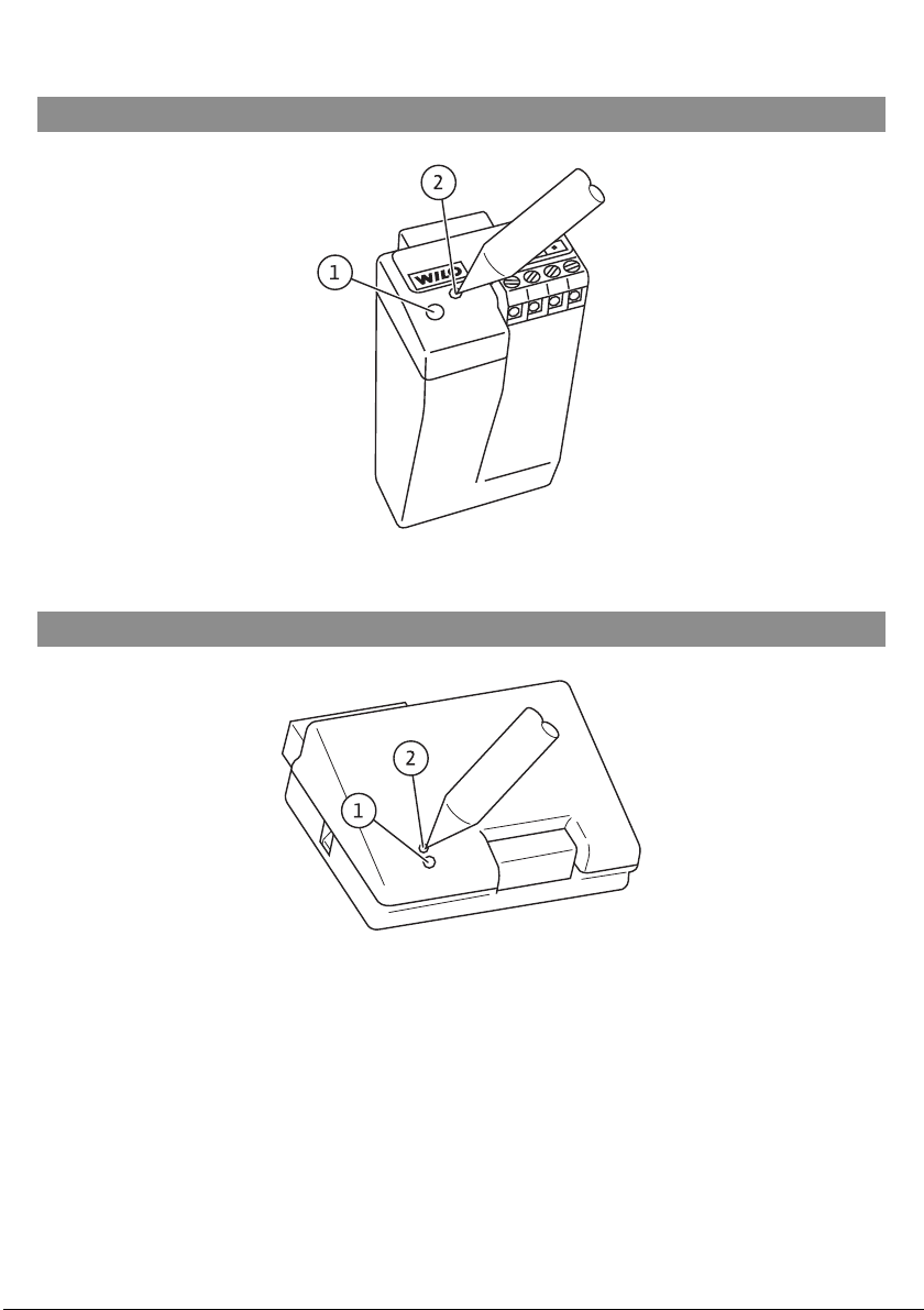
Fig.5a: IF-Modul Stratos LON
Fig.5b: IF-Modul LON
Page 8

D Einbau- und Betriebsanleitung 2
GB Installation and operating instructions 39
Page 9
Deutsch
Einbau- und Betriebsanleitung
1 Allgemeines
1.1 Über dieses Dokument
Die Sprache der Originalbetriebsanleitung ist Deutsch. Alle weiteren Sprachen
dieser Anleitung sind eine Übersetzung der Originalbetriebsanleitung.
Die Einbau- und Betriebsanleitung ist Bestandteil des Produktes. Sie ist jederzeit in Produktnähe bereitzustellen. Das genaue Beachten dieser Anweisung ist
Voraussetzung für den bestimmungsgemäßen Gebrauch und die richtige Bedienung des Produktes.
Die Einbau- und Betriebsanleitung entspricht der Ausführung des Produktes
und dem Stand der zugrunde gelegten sicherheitstechn ischen Vorschriften und
Normen bei Drucklegung.
Diese Einbau- und Betriebsanleitung ist als Ergänzung zur Einbau- und
Betriebsanleitung der an den LON-Bus angeschlossenen Pumpen zu betrachten.
2Sicherheit
Diese Betriebsanleitung enthält grundlegende Hinweise, die bei Montage,
Betrieb und Wartung zu beachten sind. Daher ist diese Betriebsanleitung unbedingt vor Montage und Inbetriebnahme vom Monteur sowie dem zuständigen
Fachpersonal/Betreiber zu lesen.
Es sind nicht nur die unter diesem Hauptpunkt Sicherheit aufgeführten allgemeinen Sicherheitshinweise zu beachten, sonde rn auch die unter den folgenden
Hauptpunkten mit Gefahrensymbolen eingefügten, speziellen Sicherheitshinweise.
2.1 Kennzeichnung von Hinweisen in der Betriebsanleitung
Symbole:
Allgemeines Gefahrensymbol
Gefahr durch elektrische Spannung
HINWEIS: ...
Signalwörter:
GEFAHR!
Akut gefährliche Situation.
Nichtbeachtung führt zu Tod oder schwersten Verletzungen.
Einbau- und Betriebsanleitung Wilo-Control IF-Modul LON / IF-Modul Stratos LON 2
Page 10

Deutsch
WARNUNG!
Der Benutzer kann (schwere) Verletzungen erleiden. 'Warnung' beinhaltet,
dass (schwere) Personenschäden wahrscheinlich sind, wenn der Hinweis
missachtet wird.
VORSICHT!
Es besteht die Gefahr, die Pumpe/Anlage zu beschädigen. 'Vorsicht' bezieht
sich auf mögliche Produktschäden durch Missachten des Hinweises.
HINWEIS:
Ein nützlicher Hinweis zur Handhabung des Produktes. Er macht auch auf mögliche Schwierigkeiten aufmerksam.
Direkt am Produkt angebrachte Hinweise wie z.B.
•Drehrichtungspfeil,
• Kennzeichen für Anschlüsse,
• Typenschild,
•Warnaufkleber,
müssen unbedingt beachtet und in vollständig lesbarem Zustand gehalten werden.
2.2 Personalqualifikation
Das Personal für die Montage, Bedienung und Wartung muss die entsprechende
Qualifikation für diese Arbeiten aufweisen. Verantwortungsbereich, Zuständigkeit und Überwachung des Personals sind durch den Betreiber sicherzustellen.
Liegen dem Personal nicht die notwendigen Kenntnisse vor, so ist dieses zu
schulen und zu unterweisen. Falls erforderlich kann dies im Auftrag des Betreibers durch den Hersteller des Produktes erfolgen.
2.3 Gefahren bei Nichtbeachtung der Sicherheitshinweise
Die Nichtbeachtung der Sicherheitshinweise kann eine Gefährdung für Personen, die Umwelt und Produkt/Anlage zur Folge haben. Die Nichtbeachtung der
Sicherheitshinweise führt zum Verlust jeglicher Schadenersatzansprüche. Die
Nichtbeachtung der Sicherheitshinweise kann zum Ve rlust jeglicher Schadenersatzansprüche führen.
Im Einzelnen kann Nichtbeachtung beispielsw eise folgende Gefährdungen nach
sich ziehen:
• Gefährdungen von Personen durch elektrische, mechanische und bakteriologische Einwirkungen,
• Gefährdung der Umwelt durch Leckage von gefährlichen Stoffen,
• Sachschäden,
• Versagen wichtiger Funktionen des Produktes/der Anlage,
• Versagen vorgeschriebener Wartungs- und Reparaturverfahren.
3 WILO SE 05/2011
Page 11

2.4 Sicherheitsbewusstes Arbeiten
Die in dieser Betriebsanleitung aufgeführten Sicherheitshinweise, die bes tehenden nationalen Vorschriften zur Unfallverhütung sowie eventuelle interne
Arbeits-, Betriebs- und Sicherheitsvorschriften des Betreibers sind zu beachten.
2.5 Sicherheitshinweise für den Betreiber
Dieses Gerät ist nicht dafür bestimmt, durch Personen (einschließlich Kinder)
mit eingeschränkten physischen, sensorischen oder geistigen Fähigkeiten oder
mangels Erfahrung und/oder mangels Wissen benutzt zu werden, es sei denn,
sie werden durch eine für ihre Sicherheit zuständige Person beaufsichtigt oder
erhielten von ihr Anweisungen, wie das Gerät zu benutzen ist.
Kinder müssen beaufsichtigt werden, um sicherzustellen, dass sie nicht mit dem
Gerät spielen.
• Führen heiße oder kalte Komponenten am Produkt/der Anlage zu Gefahren,
müssen diese bauseitig gegen Berührung gesichert sein.
• Berührungsschutz für sich bewegende Komponenten (z.B. Kupplung) darf bei
sich im Betrieb befindlichem Produkt nicht entfernt werden.
• Leckagen (z.B. Wellendichtung) gefährlicher Fördermedien (z.B. explosiv, giftig,
heiß) müssen so abgeführt werden, dass keine Gefährdung für Personen und die
Umwelt entsteht. Nationale gesetzliche Bestimmungen sind einzuhalten.
• Gefährdungen durch elektrische Energie sind auszuschließen. Weisungen lokaler oder genereller Vorschriften [z.B. IEC, VDE usw.] und der örtlichen Energieversorgungsunternehmen sind zu beachten.
Deutsch
2.6 Sicherheitshinweise für Inspektions- und Montagearbeiten
Der Betreiber hat dafür zu sorgen, dass alle Montage- und Wartungsarbeiten
von autorisiertem und qualifiziertem Fachpersonal ausgeführt werden, das sich
durch eingehendes Studium der Betriebsanleitung ausreichend informiert hat.
Die Arbeiten an dem Produkt/der Anlage dürfen nur im Stillstand durchgeführt
werden. Die in der Einbau- und Betriebsanleitung beschriebene Vorgehensweise zum Stillsetzen des Produktes/der Anlage muss unbedingt eingehalten
werden.
Unmittelbar nach Abschluss der Arbeiten müssen alle Sicherheits- und Schutzeinrichtungen wieder angebracht bzw. in Funktion gesetzt werden.
2.7 Eigenmächtiger Umbau und Ersatzteilherstellung
Eigenmächtiger Umbau und Ersatzteilherstellung gefährden die Sicherheit des
Produktes/Personals und setzen die vom Hersteller abgegebenen Erklärungen
zur Sicherheit außer Kraft.
Veränderungen des Produktes sind nur nach Absprache mit dem Hersteller
zulässig. Originalersatzteile und vom Hersteller autorisiertes Zubehör dienen
der Sicherheit. Die Verwendung anderer Teile hebt die Haftung für die daraus
entstehenden Folgen auf.
Einbau- und Betriebsanleitung Wilo-Control IF-Modul LON / IF-Modul Stratos LON 4
Page 12
Deutsch
2.8 Unzulässige Betriebsweisen
Die Betriebssicherheit des gelieferten Produktes ist nur bei bestimmungsgemäßer Verwendung entsprechend Abschnitt 4 der Betriebsanleitung gewährleistet. Die im Katalog/ Datenblatt ange gebenen Grenzwerte dürfen auf keinen Fall
unter- bzw. überschritten werden.
3 Transport und Zwischenlagerung
Bei Erhalt Produkt sofort auf Transportschäden überprüfen. Bei Festst ellung von
Transportschäden sind die notwendigen Schritte innerhalb der entsprechenden
Fristen beim Spediteur einzuleiten.
VORSICHT! Beschädigungsgefahr für das IF-Modul!
Gefahr der Beschädigung durch unsachgemäße Handhabung bei Transport
und Lagerung.
• Die IF-Module sind bei Transport und Zwischenlagerung gegen Feuchtigkeit,
Frost und mechanische Beschädigung zu schützen.
• Die IF-Module dürfen keinen Temperaturen außerhalb des Bereiches von
- 10°C bis + 70°C ausgesetzt werden.
4 Bestimmungsgemäße Verwendung
Das IF-Modul LON bzw. Stratos LON dient zum Anschluss von elektronisch
geregelten Nassläufer- oder Trockenläuferpumpen an ein LON-Netzwerk. Über
den LON-Bus können der Pumpe Sollwerte, Betriebsarten und die Daten externer Sensoren vorgegeben werden und aktuelle Betriebsdaten und Fehlermeldungen können von der Pumpe übermittelt werden.
Gleichzeitig bietet das IF-Modul LON/Stratos LON die Möglichkeit, über eine
weitere Schnittstelle DP zwei Pumpen zu einer Doppelpumpe zusammenzuschalten. Diese Schnittstelle ist separat ausgeführt, es handelt sich nicht um
eine auf LON basierende Schnittstelle. Deshalb wird der LON-Bus für die Doppelpumpenschnittstelle nicht belastet und die Slave-Pumpe kann mit einem
kostengünstigen IF-Modul PLR ausgestattet werden.
5 WILO SE 05/2011
Page 13
Anschließbare Pumpentypen:
Deutsch
Wilo-IF-Modul Stratos LON
für Nassläuferpumpen
•Wilo-Stratos
•Wilo-Stratos-D
•Wilo-Stratos-Z
•Wilo-Stratos-ZD
• weitere: siehe www.wilo.de/automation
Wilo-IF-Modul LON
für Trockenläuferpumpen
• Wilo-Stratos GIGA
• Wilo-VeroLine-IP-E/DP-E
• Wilo-VeroTwin-IL-E/DL-E
• Wilo-Economy MHIE
• Wilo-Multivert MVIE (1,1-7,5 kW)
• Wilo-Helix VE
• Wilo-Helix Excel
• weitere: siehe www.wilo.de/automation
Tabelle 4.1
5 Angaben über das Erzeugnis
5.1 Typenschlüssel
Beispiel: Wilo-Control IF-Modul LON
Control Baureihenbezeichnung
Typenbezeichnung: IF-Modul LON
IF-Modul Stratos LON
5.2 Technische Daten
Schnittstelle: TP/FT10
Klemmenquerschnitt:
Buskabel:
max. Länge Buskabel: • 900 m bei Bustopologie mit max. 3 m langen Stich-
Programm-ID (Software): 9F:FF:CC:51:14:06:04:05
Software-Version:
2,5 mm²
paarweise verdrillt, geschirmt
leitungen
• 450 m bei freier Topologie, dabei max. 250 m zwischen 2 untereinander kommunizierenden Knoten
3.00 oder höher
Einbau- und Betriebsanleitung Wilo-Control IF-Modul LON / IF-Modul Stratos LON 6
Page 14

Deutsch
5.3 Standards
Das IF-Modul LON entspricht folgenden Standards:
• LonMark Application Layer Interoperability Guidelines Version 3.4
• LonMark Layers 1-6 Interoperability Guidelines Version 3.4
• LonMark node object 0000_20
• LonMark pump controller object 8120_10
• LonMark Resource Files Version 13.04
Die gesamte Dokumentation ist unter www.wilo.de/automation zu finden.
5.4 Lieferumfang
• IF-Modul LON oder IF-Modul Stratos LON
• Metallische Kabelverschraubung Pg7 (nur IF-Modul Stratos LON)
• Metallische Kabelverschraubung Pg9 (nur IF-Modul Stratos LON)
• Einbau- und Betriebsanleitung
• CD mit ergänzenden Informationen
5.4.1 Auslieferungszustand
Gemäß den LonMark Application Layer Interoperability Guidelines wird das IFModul LON im Zustand “Application unconfigured” ausgeliefert. In diesem
Zustand kann das IF-Modul LON über den LON-Bus angesprochen werden, aber
die Applikation, die normalerweise die Kommunikation mit der Pumpe ausführt,
ist noch nicht in Betrieb. Somit ist nach dem Aufstecken des IF-Moduls LON und
dem Einschalten der Stromversorgung der Pumpe noch keine Aktivität zu
sehen.
6 Beschreibung und Funktion
6.1 Beschreibung der Objekte
Im IF-Modul LON sind 2 Objekte realisiert, das Knoten-Objekt und das PumpenObjekt. Das Knoten-Objekt dient zur Steuerung einzelner Objekte innerhalb des
Knotens, hier werden auch zentral Fehler signalisiert, die in den einzelnen
Objekten auftreten.
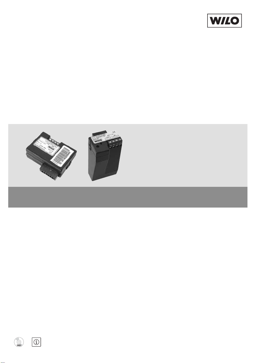
Fig.1a zeigt das Knoten-Objekt (Node Object) mit den zugehörigen Ne tz we rk variablen und Fig.1b zeigt das Pumpen-Objekt (Pump Controller Object) mit
den zugehörigen Netzwerkvariablen.
HINWEIS:
• Doppelpumpen sind immer mit dem integrierten Doppelpumpenmanagement
zu betreiben.
• Bei Doppelpumpen wird das IF-Modul LON an den Master angeschlossen.
• Wird bei Doppelpumpen das integrierte Doppelpumpenmanagement nicht
benutzt, so sind die beiden Antriebe wie zwei separate Einzelpumpen zu behandeln. In diesem Fall sind zwei IF-Module LON erforderlich.
• Steuerfunktionen beziehen sich auf die Doppelpumpe als gesamtes Aggregat.
7 WILO SE 05/2011
Page 15

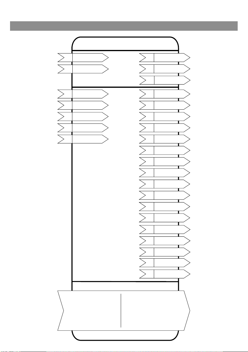
6.2 Beschreibung der Netzwerkvariablen
6.2.1 Wertebereiche und Auflösungen der Netzwerkvariablen Eingänge
Data Range and
effective
resolution WILO
.object_id: 0 - 1
.object_request:
RQ_NORMAL
RQ_DISABLED
RQ_ENABLE
RQ_UPDATE_STATUS
RQ_REPORT_MASK
RQ_CLEAR_STATUS
.state: 0 – 1
.value: 0.0 – 100.0%
HVAC_AUTO
HVAC_MRNG_WRMUP
HVAC_PRE_COOL
HVAC_ECONOMY
.state: 0 – 1
.value: 0.0 – 100.0%
0 - 100%
Eff. Resolution: 0.5%
Range depends on
Pumptype.
Eff. Resol.: 0.981kPa
0–3276.6kPa
Eff. Resol.: 0.981kPa
-273.1 – 327.6 °C
Invalid Data
-
Default Value
-
Resolution
-
-
SCPTsetpoint
-
0xFF
(HVAC_NUL)
HVAC_AUTO
-
.state: 0xFF
.state: 0xFF
-
.value: 0xFF
0x7FFF
0x7FFF
0.005 %
0x7FFF
0x7FFF
0.1 kPa
0x7FFF
0x7FFF
0.1 kPa
0x7FFF
0x7FFF
0.01°C
Deutsch
Eff. Resol.: 0.1°C
Data Range
and Units
Receive
Heartbeat
No.
Object
NVT
Mand.
Opt.
Input-
Networkvariable
-
no
1
0
SNVT_obj_request
M
nviRequest
.state: 0 – 1
.value: 0.0
- 100.0%
enum 0 ... 17
no
no
1
2
1
1
SNVT_switch
SNVT_hvac_mode
M
M
nviPumpSetpoint
nviPumpOpMode
(hvac_t)
.state: 0 – 1
.value: 0.0
... +100.0%
-163.84
no
no
6
7
1
1
SNVT_switch
SNVT_lev_percent
O
O
nviPumpOvdStop
nviOvdSpeed
... +163.83 %
-3276.8
... +3276.6 kPa
no
8
1
SNVT_press
O
nviOvdPress
-3276.8
... +3276.6 kPa
-273.17
yes
yes
10
12
1
1
SNVT_press
SNVT_temp_p
O
O
nviRemotePress
nviRemoteTemp
... +327.66 °C
Tabelle 6.2.1
Einbau- und Betriebsanleitung Wilo-Control IF-Modul LON / IF-Modul Stratos LON 8
Page 16

Deutsch
Send when value
Range and effective
Invalid
Resolution
6.2.2 Wertebereiche und Auflösungen der Netzwerkvariablen Ausgänge
changes more
than
Send upon nviRequest:
resolution WILO
Data
update
invalid_id
invalid_request
disabled
electrical_fault
unable_to_measure
manual_control
-
5 % of nroPump-
Char.pressMax
or 2 % of nroPump-
Char.speedMax resp.,
control mode changes
5 % of
nroPumpChar.pressMax
5 % of
nroPumpChar.flowMax
1 kWh
10 % of max. Power
10 % of max. Power
10 h
2 % of nroPump-
Char.speedMax
5 °C
immediately
/h
3
in_alarm
0 – 100.0%
Res: 0.2%
0x7FFF
0.005 %
Range depends on
Pumptype
0x7FFF
0.1 kPa
Res. :0.981 kPa
Range depends on
Pumptype
Res : 0.1 m
0xFFFF
/h
3
0.01 m
/h
3
0 – 65535 kWh
-
1 kWh
Res: 1 kWh
0 – 6553W
-
0.1 W
Res: min. 1 W
0 – 65.5 kW
-
0.1 kW
Res: 0.1 kW
0 – 65535 h
Res: 10 h
-
1 h
0 – 65535 rpm
Res: min.1 rpm
-
1 rpm
-50 °C – 205°C
Res : min. 0.1 °C
DCM_SPEED_CONST
0x7FFF
0xFF
0.01 °C
-
DCM_PRESS_CONST
DCM_PRESS_COMP
DCM_PRESS_AUTO
DCM_NUL
0 – 65535 kWh
0 – 6553.5 W
0 – 6553.5 kW
0 – 65535 h
0 – 65535 rpm
-273.17
– 327.66 °C
ENUM 0 – 29
yes
no
21
1
SNVT_temp_p
O
nvoFluidTemp
(device_c_mode_t)
yes
yes
5
1
SNVT_dev_c_mode
M
nvoControlMode
Data Range
and Units
Min.
Send
Time
Send
Heartbt /
Ack
No.
Obj
NVT
Mand.
Opt.
Output-
Networkvariable
yes
yes
2
0
SNVT_obj_status
M
nvoStatus
no
no
8
0
SNVT_address
O
nnvoFileDirectory
-163.84
– 163.83 %
yes
yes
3
1
SNVT_lev_percent
M
nvoPumpCapacity
-3276.8
– 3276.6 kPa
yes
no
14
1
SNVT_press
O
nvoPressure
0 – 655.34 m
yes
yes
no
no
15
24
1
1
SNVT_flow_p
SNVT_elec_kWh
O
O
nvoFlow
nvoEnergyConsum
yes
yes
no
no
22
23
1
1
SNVT_power
SNVT_power_kilo
O
O
nvo Power
nvoPowerkilo
yes
yes
no
no
18
16
1
1
SNVT_time_hour
SNVT_rpm
O
O
nvoRuntime
nvoSpeed
Tabelle 6.2.2
9 WILO SE 05/2011
Page 17

Send when value
changes more
than
Range and effective
resolution WILO
Invalid
Data--
Resolution
immediately
service_required
-
immediately
sf_voltage_low
-
Deutsch
immediately
sf_voltage_high
sf_phase
sf_no_fluid
df_motor_temp
df_motor_failure
df_pump_blocked
df_elect_temp
df_elect_failure_nf
df_elect_failure
df_sensor_failure
device_fault
supply_fault
speed_low
speed_high
setpt_out_of_range
local_control
-
-
running
remote_press
remote_temp
immediately
HVAC_AUTO
HVAC_MRNG_WRMUP
HVAC_PRE_COOL
0xFF
-
HVAC_ECONOMY
immediately
immediately
immediately
immediately
immediately
after reset
HVAC_NUL
.state: 0 – 1
.value: 0.0%, 100.0%, 0xFF
Error Codes WILO
Error Codes WILO
device_fault
supply_fault
running
device_fault
supply_fault
running
Pump Type List WILO
.state: 0xFF
0xFFFF
0xFFFF
-
-
-
-
---
-
-
Data Range
and Units
bitset
Min.
Send
Send
Heartbt /
No.
Obj
NVT
Mand.
Opt.OO
Output-
Networkvariable
Time
yes
Acknono
20
1
SNVT_dev_maint
nvoMaintenance
bitset
yes
19
1
SNVT_dev_fault
nvoPumpFault
bitset
yes
yes
13
1
SNVT_dev_status
O
nvoPumpStatus
ENUM 0 – 17
(hvac_t)
yes
yes
4
1
SNVT_hvac_mode
M
nvoEffOpMode
.state: 0 – 1
.value: 0.0-100.0%,
bitset
yes
yes
yes
yes
nonono
173839
1
SNVT_switch
O
nvoPumpOverride
no
40
111
SNVT_count
SNVT_count
SNVT_dev_status
OOO
nvoCurrentErrorM
nvoCurrentErrorS
nvoPumpStatusM
bitset
yes
yes
no
no
41
42
1
1
SNVT_dev_status
SNVT_count
O
O
nvoPumpStatusS
nvoPumpType
Tabelle 6.2.2, Fortsetzung
Einbau- und Betriebsanleitung Wilo-Control IF-Modul LON / IF-Modul Stratos LON 10
Page 18

Deutsch
Data Range and effective
Number
Object
CPT / NVT
6.2.3 Wertebereiche und Auflösungen der Netzwerkvariablen
Konfigurationseingänge
resolution WILO
0–0d17h59m59s
eff. Res: 1s-0–6553s
eff. Res: 1s
0–6553s
eff. Res: 1s
0–6553s
eff. Res: 1s
DCM_SPEED_CONST
DCM_PRESS_CONST
DCM_PRESS_COMP
DCM_PRESS_AUTO
0 – 3276.7 kPa
eff. Res: 0.981 kPa
0 – 3276.7 kPa
eff. Res: 0.981 kPa
-273.1 – 327.6 °C
eff. Res: 0.1°C
-273.1 – 327.6 °C
eff. Res: 0.1°C
.TempMin, .TempMax:
0 – 110 °C
eff. Res: 0.1°C
221748
0
SCPTmaxSndT
0
1
SCPTlocation
SCPTmaxRcvTime
49
52
1
1
SCPTmaxSendTime
SCPTminSendTime
238
1
SCPTdeviceControlMode
239
1
SCPTminRemotePressureSetpoint
240
243
1
1
SCPTmaxRemotePressureSetpoint
SCPTminRemoteTempSetpoint
244
1
1
SCPTmaxRemoteTempSetpoint
UCPTPressTemp
.PressMin, .PressMax:
0 – 3276.7 kPa
eff. Res: 0.981kPa
.state: 0–1
.value: 0–255
213
1
SCPTsetpoint
Mandatory /
Optional /
User
O
O
O
M
O
O
Input Configuration Variable
nciMaxStsSendT
nciLocation
nciRcvHrtBt
nciSndHrtBt
nciMinOutTm
nciControlMode
O
nciRemMinPress
O
O
nciRemMaxPress
nciRemMinTemp
O
U
nciRemMaxTemp
nciPressTemp
O
nciSetpPreset
Tabelle 6.2.3
11 WILO SE 05/2011
Page 19

6.2.4 Wertebereiche und Auflösungen der Netzwerkvariablen
Konfigurationsausgänge
Output
Configuration
Mandat./
Optional
CPT/NVT Object Number Value
Variable
nciDevMajVer O SCPTdevMajVer 0 165 03
nciDevMinVer O SCPTdevMinVer 0 166 00
nroPumpChar M SCPTpumpCharacteristic 1 233 depends on
pumptype
nciObjMajVer O SCPTobjMajVer 1 167 03
nciObjMinVer O SCPTobjMinVer 1 168 00
6.2.5 Beschreibung der Netzwerkvariablen
Objekt-Request
network input SNVT_obj_request nviRequest
Diese Eingangs-Netzwerkvariable veranlasst verschiedene Operationen, die
den Knoten- und Objektstatus betreffen. Sie besteht aus 2 Bytes, dem ID-Byte
und dem Wert-Byte. Das ID-Byte gibt die Nummer des Objektes an, auf das sich
der Request bezieht. Der ID-Wert 0 bezieht sich auf das Knoten-Objekt, hier
haben Requests evtl. auch Auswirkungen auf alle anderen Objekte. Der ID-Wert
1 bezieht sich auf das pump-controller-Objekt.
Wertebereich:
Wert Funktion bei ID = 0 Funktion bei ID = 1
RQ_NORMAL Normalbetrieb aller Objekte Normalbetrieb pump control-
ler
RQ_DISABLED Stop aller Objekte Stop des pump controller
RQ_ENABLE Enable des Knotenobjekts Enable des pump controller
RQ_UPDATE_STATUS Status Knotenobjekt aktuali-
sieren (Oderverknüpfung über
Status pump controller aktu-
alisieren
alle Objekte)
RQ_REPORT_MASK Unterstützte Statusmeldun-
gen Knotenobjekt (Oderver-
Unterstützte Statusmeldun-
gen pump controller
knüpfung über alle Objekte)
RQ_CLEAR_STATUS Bestimmte Statusmeldungen
in allen Objekten löschen
Bestimmte Statusmeldungen
des pump controller löschen
Deutsch
Einbau- und Betriebsanleitung Wilo-Control IF-Modul LON / IF-Modul Stratos LON 12
Page 20
Deutsch
Objekt-Status
network output SNVT_obj_status nvoStatus
Diese Ausgangs-Netzwerkvariable liefert Statusinformationen zu den einzel-
nen Objekten. Die Informationen sind Bit-Codiert. Alle Bits sind nach einem
Reset wieder gelöscht.
Wertebereich:
Bit Funktion
invalid_id Es wurde ein nicht existierendes Objekt angesprochen
invalid_request Es wurde ein unbekannter Request gesendet
disabled Das betreffende Objekt ist abgeschaltet
electrical_fault Das pump-controller-Objekt meldet einen elektrischen Fehler
unable_to_measure Das pump-controller-Objekt kann nicht mit der Pumpe kom-
munizieren
manual_control Das pump-controller-Objekt wird durch Hardware-Vorgaben
an der Pumpe an der Steuerung gehindert (ext. Off, ext. Min, IR-
Monitor)
in_alarm Das pump-controller-Objekt meldet einen Fehler
report_mask Signalisiert, daß nvoStatus aufgrund einer vorangegangenen
RQ_REPORT_MASK-Aufforderung die Status-Maske enthält,
also die Liste aller Bits, die unterstützt werden.
File Directory Address
network output SNVT_address nvoFileDirectory
Diese Netzwerkvariable gibt die Startadresse des Konfigurationsdatei-
Verzeichnisses an.
Weitere Informationen stehen in der LONmark Dokumentation des Knotenobjektes.
13 WILO SE 05/2011
Page 21

Maximum Status Send Time
network input config SNVT_elapsed_tm nciMaxStsSendT
Diese optionale Eingangs-Konfigurations-Netzwerkvariable definiert einen
Zeittakt, in welchem die Objekt-Stati automatisch aktualisiert werden. Es werden abwechselnd der Status des node-Objekts und der des pump-controllerObjekts aktualisiert.
Wertebereich:
0d0h0m0s0ms – 0d17h59m59s999ms (in 1 s-Schritten). Der Wert
0d0h0m0s0ms schaltet das automatische Aktualisieren aus.
Startwert: 0d0h0m0s0ms (automatisches Aktualisieren ausgeschaltet)
SCPT Reference: SCPTmaxSendT (22)
Device Major Version
network output config unsigned short nciDevMajVer
Diese optionale Ausgangs-Konfigurations-Netzwerkvariable liefert das High-
byte der Modulversion.
SCPT Reference: SCPTdevMajVer (165)
Device Minor Version
network output config unsigned short nciDevMinVer
Diese optionale Ausgangs-Konfigurations-Netzwerkvariable liefert das Low-
byte der Modulversion.
SCPT Reference: SCPTdevMinVer (166)
Deutsch
Location Label
network input config SNVT_str_asc nciLocation
Diese optionale Eingangs-Konfigurations-Netzwerkvariable kann genutzt wer-
den, um Informationen über den Einbauort der Pumpe abzuspeichern, die über
den im Neuron Chip abgelegten, nur 6Byte umfassenden Informationsstring
hinausgehen.
Wertebereich:
Beliebiger, NUL-terminierter ASCII-String von max. 31 Bytes Länge (incl. NUL).
Startwert:
ASCII-String, der nur aus NUL ("\0") besteht.
SCPT Reference: SCPT_location (17)
Einbau- und Betriebsanleitung Wilo-Control IF-Modul LON / IF-Modul Stratos LON 14
Page 22
Deutsch
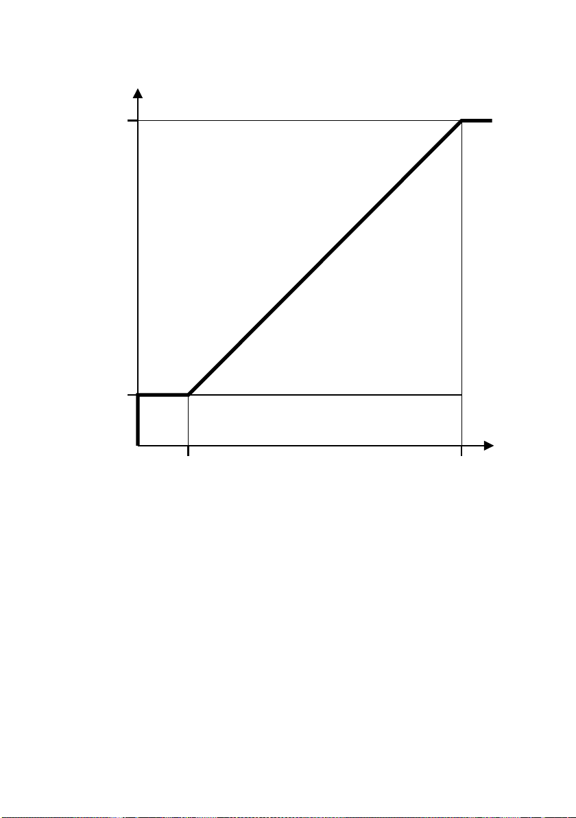
Sollwertobergrenze
(Hersteller- ,
Pumpen- und
Regelartspezifisch)
Tatsächlicher Sollwert [%]
STOP
X
100%
Pump Setpoint
nviPumpSetpoint
[%]
Sollwertuntergrenze
(Hersteller- ,
Pumpen- und
Regelartspezifisch)
X = ( Sollwertuntergrenze / Sollwertobergrenze ) * 100%
Pump Setpoint
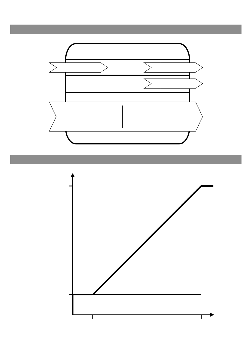
network input SNVT_switch nviPumpSetpoint
Diese Eingangs-Netzwerkvariable dient zum Ein- und Ausschalten der Pumpe
und zur Vorgabe eines Sollwertes.
Die Netzwerkvariable besteht aus einem Status-Byte, in welchem der Einschaltzustand übertragen wird, und aus einem Werte-Byte, in welchem der Sollwert übertragen wird.
Bei Vorgabe eines Status-Bytes von 0 ist die Pumpe ausgeschaltet, bei Vorgabe
eines Status-Bytes von 1 hängt der Einschaltzustand noch vom Werte-Byte ab.
Bei Vorgabe eines Sollwertes von 0% wird die Pumpe ausgeschaltet, bei Vorgabe eines Sollwertes größer 0% ist die Pumpe eingeschaltet, wenn das StatusByte 1 ist. Der Sollwert kann in 0,5%-Schritten verändert werden.
Bei Vorgabe von Sollwerten oberhalb der Sollwertobergrenze wird auf die Soll-
15 WILO SE 05/2011
wertobergrenze begrenzt, entsprechend wird bei Vorgabe von Sollwerten
unterhalb der Sollwertuntergrenze auf die Sollwertuntergrenze begrenzt.
Page 23

Die Sollwertober- und Sollwertuntergrenzen können sich ändern, wenn die
Pumpe mit einem externen Sensor betrieben wird
(siehe nviRemotePress, nciRemMinPress und nciRemMaxP re ss ).
Wertebereich:
Status Wert Funktion
0 0 – 255 STOP
10 STOP
1 1 – 200 0,5 – 100,0%
1 201 - 255 100,0%
Startwert: Status = 1, Wert = 200 = 100,0%. Startwert entspricht der Vorgabe,
die im Konfigurationsparameter SCPTsetpoint nichtflüchtig abgespeichert werden kann.
Requested Pump-Operating Mode
network input SNVT_hvac_mode nviPumpOpMode
Diese Eingangs-Netzwerkvariable dient zur Vorgabe eines Betriebsmodus. Wird
ein Betriebsmodus vorgegeben, der nicht definiert oder ungültig ist, verbleibt
die Pumpe im aktuellen Modus.
Wertebereich:
Wert Funktion Bemerkung
HVAC_AUTO Normalbetrieb Sollwert über
nviPumpSetpoint
HVAC_MRNG_WRMUP Aufwärmbetrieb Maximale Drehzahl
HVAC_PRE_COOL Abkühlbetrieb Maximale Drehzahl
HVAC_ECONOMY Energiesparbetrieb Drehzahl Absenkbetrieb
(Pumpentypspezifisch)
HVAC_NUL Ungültig
Deutsch
Startwert: HVAC_AUTO
Pump Capacity
network output SNVT_lev_percent nvoPumpCapacity
Diese Ausgangs-Netzwerkvariable liefert den aktuellen Arbeitspunkt der
Pumpe als auf den maximalen Sollwert bezogenen Prozentwert.
Bei Verwendung eines externen Druck- oder Temperatursensors liefert diese
Variable den Sensorwert als auf den maximalen Sensorwert bezogenen
Prozentwert.
Einbau- und Betriebsanleitung Wilo-Control IF-Modul LON / IF-Modul Stratos LON 16
Page 24

Deutsch
Wertebereich:
-163,840% – 163,830% (in 0,02%-Schritten). Der Wert 163,835% stellt einen
ungültigen Wert dar.
Übertragung:
Dieser Wert wird automatisch übertragen, wenn die Abweichung vom zuletzt
übertragenen Wert mehr als 5% des Wertes in nroPumpChar.pressMax (bei Differenzdruckregelung) oder 2% des Wertes in nroPumpChar.sp eedMax (bei
Drehzahlsteller) beträgt. Außerdem wird dieser Wert regelmäßig übertragen,
wenn der Konfigurationseingang nciSndHrtBt mit einem gültigen Zeittakt
beschrieben wurde. Ebenso wird dieser Wert übertragen, wenn durch vorrangige Vorgaben oder Anschließen eines externen Sensors die Regelart geändert
wurde.
Übertragungstakt:
Durch Beschreiben des Konfigurationseingangs nciMinOutTm mit einem gültigen Zeittakt kann die minimale Zeit zwischen zwei Übertragungen einer Netzwerkvariablen eingestellt werden.
Voreingestellter Servicetyp: acknowledged
Effective Operating Mode
network output SNVT_hvac_mode nvoEffOpMode
Diese Ausgangs-Netzwerkvariable liefert den aktuellen Betriebsmodus der
Pumpe. Dieser Wert entspricht der Vorgabe in der Eingangs-Netzwerkvaria blen
nviPumpOpMode, wenn nicht über lokale Vorgaben an der Pumpe (ext. off, ext.
min oder IR-Monitor) ein anderer Betriebsmodus erzwungen wird.
Wertebereich:
Wert Funktion Bemerkung
HVAC_AUTO Normalbetrieb Sollwert über
nviPumpSetpoint
HVAC_MRNG_WRMUP Aufwärmbetrieb Maximale Drehzahl
HVAC_PRE_COOL Abkühlbetrieb Maximale Drehzahl
HVAC_ECONOMY Energiesparbetrieb Drehzahl Absenkbetrieb
(Pumpentypspezifisch)
HVAC_OFF Offlinebetrieb Ext. Off oder Manueller
Betrieb über IR-Monitor
HVAC_NUL Ungültig
Übertragung:
Dieser Wert wird bei jeder Änderung automatisch übertragen.
Außerdem wird dieser Wert regelmäßig übertragen, wenn der Konfigurationseingang nciSndHrtBt mit einem gültigen Zeittakt beschrieben wurde.
17 WILO SE 05/2011
Page 25

Übertragungstakt:
Durch Beschreiben des Konfigurationseingangs nciMinOutTm mit einem gültigen Zeittakt kann die minimale Zeit zwischen zwei Übertragungen einer Netzwerkvariablen eingestellt werden.
Voreingestellter Servicetyp: acknowledged
Effective Device-Control Mode
network output SNVT_dev_c_mode nvoControlMode
Diese Ausgangs-Netzwerkvariable liefert die aktuelle Regelart der Pumpe.
Wertebereich:
Wert Funktion
DCM_SPEED_CONST Drehzahlsteller
DCM_PRESS_CONST Differenzdruck konstant / Druck konstant
DCM_PRESS_COMP Differenzdruck volumenstromabhängig
DCM_PRESS_AUTO Differenzdruck temperaturabhängig
Übertragung:
Dieser Wert wird bei jeder Änderung automatisch übertragen.
Außerdem wird dieser Wert regelmäßig übertragen, wenn der Konfigurationseingang nciSndHrtBt mit einem gültigen Zeittakt beschrieben wurde.
Übertragungstakt:
Durch Beschreiben des Konfigurationseingangs nciMinOutTm mit einem gültigen Zeittakt kann die minimale Zeit zwischen zwei Übertragungen einer Netzwerkvariablen eingestellt werden.
Voreingestellter Servicetyp: acknowledged
Deutsch
Pump Override Stop Command
network input SNVT_switch nviPumpOvdStop
Diese optionale Eingangs-Netzwerkvariable stellt eine vorrangige Ein-/Aus-
schaltfunktion zur Verfügung und ist für z. B. Wartungsarbeiten gedacht. Die
Netzwerkvariable besteht aus einem Status-Byte und aus einem Werte-Byte.
Die Vorgabe “OVDSTOP” hat Vorrang vor dem in nviPumpSetpoint vorgegebenen Sollwert sowie vor den in nviOvdSpeed und nviOvdPress vorgegebenen
vorrangigen Sollwerten.
In der Ausgangs-Netzwerkvariable nvoPumpOverride wird eine vorrangige Vorgabe signalisiert.
Einbau- und Betriebsanleitung Wilo-Control IF-Modul LON / IF-Modul Stratos LON 18
Page 26

Deutsch
Wertebereich
Status Wert Funktion
0 0 – 255 NORMAL
10 NORMAL
1 1 – 255 OVDSTOP
255 0 – 255 ungültig (NORMAL)
Startwert: Status = 255, Wert = 255
Override Setpoint for Speed
network input SNVT_lev_percent nviOvdSpeed
Diese optionale Eingangs-Netzwerkvariable dient zur vorrangigen Vorgabe
eines Drehzahlsollwertes, z. B. für Wartungsarbeiten. Der Wert wird in Prozent
des maximalen Wertes der Pumpe vorgegeben. Wenn ein gültiger Wert em pfangen wird , wird der über nviPumpSetpoint oder nviOvdPress vorgegebene Sollwert überschrieben und automatisch auf die Regelart Drehzahlsteller
umgeschaltet.
Ein ungültiger Wert in allen vorrangigen Sollwertvorgaben nviOvdSpeed und
nviOvdPress sowie eine Vorgabe “Normal” über nviPumpOvdStop setzt die
Pumpe zurück in den Normalzustand.
In der Ausgangs-Netzwerkvariablen nvoPumpOverride wird eine vorrangige
Vorgabe signalisiert.
Wertebereich:
-163,84% - 163,83% (in 0,005%-Schritten). Der Wert 163,835% stellt einen
ungültigen Wert dar.
Werte kleiner als 0% und Werte größer als 100% werden entsprechend
begrenzt und nvoPumpStatus.pump_ctrl.setpt_out_of_range wird gesetzt.
Startwert: 163,835%
Override Setpoint for Pressure
network input SNVT_press nviOvdPress
Diese optionale Eingangs-Netzwerkvariable dient zur vorrangigen Vorgabe
eines Differenzdrucksollwertes, z. B. für Wartungsarbeiten. Der Wert wird in kPa
vorgegeben. Wenn ein gültiger Wert empfangen wird, wird der über nviPumpSetpoint oder nviOvdSpeed vorgegebene Sollwert überschrieben und automatisch auf die Regelart Differenzdruck konstant umgeschaltet.
Ein ungültiger Wert in allen vorrangigen Sollwertvorgaben nviOvdSpeed und
nviOvdPress sowie eine Vorgabe “Normal” über nviPumpOvdStop setzt die
Pumpe zurück in den Normalzustand. In der Ausgangs-Netzwerkvariablen
nvoPumpOverride wird eine vorrangige Vorgabe signalisiert.
19 WILO SE 05/2011
Page 27

Wertebereich:
-3276,8 – 3276,6 kPa (in 0,1 kPa-Schritten). Der Wert 3276,7 kPa stellt einen
ungültigen Wert dar.
Werte außerhalb des für die jeweilige Pumpe gültigen Bereichs werden entsprechend begrenzt und nvoPumpStatus.pump_ctrl.setpt_out_of_range wird
gesetzt.
Startwert: 3276,7kPa
Remote Pressure-Sensor Input
network input SNVT_press nviRemotePress
Diese optionale Eingangs-Netzwerkvariable erlaubt den Einsatz eines externen
Differenzdruck-Sensors für die Regelung der Pumpe. Bei Empfang eines gültigen Wertes schaltet die Pumpe automatisch auf die Regelart Differenzdruck
konstant um. Die Regelung mit einem externen Sensor wird in der Netzwerkvariablen nvoPumpStatus.pump_ctrl.remote_press angezeigt.
Die Ausgangs-Netzwerkvariable nvoPumpCapacity zeigt dann den aktuellen
Sensor-Istwert in Prozent vom Maximum des Sensorbereiches an. Die Ausgangs-Netzwerkvariable nvoPressure liefert immer den von der Pumpe intern
ermittelten Differenzdruck-Istwert, der durchaus vom Sens orwert abweichen
kann. Dies soll zur Analyse des Systemverhaltens dienen. Bei Benutzung der
Netzwerk-Eingangsvariablen nviRemotePress wird der Differenzdruck-Sollw ert
weiterhin über die Eingangs-Netzwerkvariable nviPumpSetpoint vorgegeben.
Wenn an die Eingangs-Netzwerkvariable nviRemotePress ein ungültiger Wert
gesendet wird oder länger als in nciRcvHrtBt festgelegt kein neuer Wert empfangen wurde, kehrt die Pumpe zur internen Regelung und zu der in nciControlMode festgelegten Regelart zurück.
Der vorrangige Sollwerteingang nviOvdSpeed setzt die Regelung mit externem
Sensor ebenfalls außer Kraft.
Vorrang nviRemotePress vor nviRemoteTemp.
Achtung: Für eine stabile Regelung muß nviRemotePress alle 3s gesendet werden. Aber selbst dann kann nicht für alle Pumpentypen garantiert werden, daß
die Regelung stabil läuft.
Wertebereich:
-3276,8 – 3276,6 kPa (in 0,1 kPa-Schritten). Der Wert 3276,7 kPa stellt einen
ungültigen Wert dar.
Startwert: 3276,7 kPa.
Deutsch
Einbau- und Betriebsanleitung Wilo-Control IF-Modul LON / IF-Modul Stratos LON 20
Page 28

Deutsch
Remote Temperature-Sensor Input
network input SNVT_temp_p nviRemoteTemp
Diese optionale Eingangs-Netzwerkvariable erlaubt den Einsatz eines externen
Temperatur-Sensors für die Regelung der Pumpe. Bei Empfang eines gültigen
Wertes schaltet die Pumpe automatisch auf die Regelart Differenzdruck temperaturabhängig um. Die Regelung mit einem externen Sensor wird in der Netzwerkvariablen nvoPumpStatus.pump_ctrl.remote_temp angezeigt.
Die Ausgangs-Netzwerkvariable nvoPumpCapacity zeigt dann den aktuellen
Sensor-Istwert in Prozent vom Maximum des Sensorbereiches an. Wenn an die
Eingangs-Netzwerkvariable nviRemoteTemp ein ungültiger Wert gesendet
wird oder länger als in nciRcvHrtBt festgelegt kein neuer Wert empfangen
wurde, kehrt die Pumpe zur internen Regelung und zu der in nciControlMode
festgelegten Regelart zurück.
Die vorrangigen Sollwerteingänge nviOvdSpeed und nviOvdPress setzen die
Regelung mit externem Sensor ebenfalls ausser Kraft.
Vorrang nviRemotePress vor nviRemoteTemp.
Wertebereich:
-273,17 ... +327,66 °C (in 0,01 °C-Schritten). Der Wert 327,67 °C stellt einen
ungültigen Wert dar.
Startwert: 327,67 °C.
Pump-Status Diagnostic Information
network output SNVT_dev_status nvoPumpStatus
Diese Ausgangs-Netzwerkvariable liefert bitcodiert In formationen über den
Pumpenzustand.
Wertebereich:
Bit Beschreibung
device_fault Pumpenfehler (siehe nvoPumpFault für genauere Informa-
tion)
supply_fault Versorgungsfehler (Netzspannung, Phase fehlt, Trockenlauf,
etc. Siehe nvoPumpFault für genauere Information)
speed_low Regeluntergrenze (Pumpe läuft auf minimaler Drehzahl, des-
halb ist geforderter Arbeitspunkt nicht erreichbar)
speed_high Regelobergrenze (Pumpe läuft auf maximaler Drehzahl, des-
halb ist geforderter Arbeitspunkt nicht erreichbar)
setpt_out_of_range Sollwertüber-/unterschreitung
local_control Lokalbetrieb (Durch ext. off, ext. min oder IR-Monitor)
running Pumpe läuft
remote_press Regelung mit externem Drucksensor
remote_temp Regelung mit externem Temperatursensor
21 WILO SE 05/2011
Page 29

Übertragung:
Dieser Wert wird bei jeder Änderung automatisch übertragen.
Außerdem wird dieser Wert regelmäßig übertragen, wenn der Konfigurationseingang nciSndHrtBt mit einem gültigen Zeittakt beschrieben wurde.
Übertragungstakt:
Durch Beschreiben des Konfigurationseingangs nciMinOutTm mit einem gültigen Zeittakt kann die minimale Zeit zwischen zwei Übertragungen einer Netzwerkvariablen eingestellt werden.
Voreingestellter Servicetyp: acknowledged
Pump Pressure
network output SNVT_press nvoPressure
Diese optionale Ausgangs-Netzwerkvariable liefert den von der Pumpe intern
ermittelten Differenzdruck zwischen den Pumpenflans chen.
Wertebereich:
0 – 3276,6 kPa ( in 0,1 kPa-Schritten). Der Wert 3276,7 kPa stellt einen ungültigen Wert dar.
Übertragung:
Dieser Wert wird automatisch übertragen, wenn die Abweichung vom zuletzt
übertragenen Wert mehr als 5% des Wertes in nroPumpChar.pressMax beträgt.
Übertragungstakt:
Durch Beschreiben des Konfigurationseingangs nciMinOutTm mit einem gültigen Zeittakt kann die minimale Zeit zwischen zwei Übertragungen einer Netzwerkvariablen eingestellt werden.
Voreingestellter Servicetyp: unacknowledged
Deutsch
Pump Flow
network output SNVT_flow_p nvoFlow
Diese optionale Ausgangs-Netzwerkvariable liefert den von der Pumpe ermit-
telten Durchfluss.
Wertebereich:
0 – 655,34 m
3
/h (in 0,01 m3/h-Schritten). Der Wert 655,35 m3/h stellt einen
ungültigen Wert dar.
Übertragung:
Dieser Wert wird automatisch übertragen, wenn die Abweichung vom zuletzt
übertragenen Wert mehr als 5% des Wertes in nroPumpChar.flowMax beträgt.
Einbau- und Betriebsanleitung Wilo-Control IF-Modul LON / IF-Modul Stratos LON 22
Page 30

Deutsch
Übertragungstakt:
Durch Beschreiben des Konfigurationseingangs nciMinOutTm mit einem gültigen Zeittakt kann die minimale Zeit zwischen zwei Übertragungen einer Netzwerkvariablen eingestellt werden.
Voreingestellter Servicetyp: unacknowledged
Pump Speed
network output SNVT_rpm nvoSpeed
Diese optionale Ausgangs-Netzwerkvariable liefert die Drehzahl der Pumpe.
Wertebereich:
0 – 65535 1/min (in eins 1/min-Schritten).
Übertragung:
Dieser Wert wird automatisch übertragen, wenn die Abweichung vom zuletzt
übertragenen Wert mehr als 2% des Wertes in nroPumpChar.speedMax beträgt.
Übertragungstakt:
Durch Beschreiben des Konfigurationseingangs nciMinOutTm mit einem gültigen Zeittakt kann die minimale Zeit zwischen zwei Übertragungen einer Netzwerkvariablen eingestellt werden.
Voreingestellter Servicetyp: unacknowledged
Pump Override Active
network output SNVT_switch nvoPumpOverride
Diese optionale Ausgangs-Netzwerkvariable liefert den Status der vorrangigen
Vorgaben.
Wertebereich:
Status Wert Funktion
00 NORMAL
1200 OVERRIDE
255 0 – 255 ungültig
Übertragung:
Dieser Wert wird bei jeder Änderung übertragen.
Übertragungstakt:
Durch Beschreiben des Konfigurationseingangs nciMinOutTm mit einem gültigen Zeittakt kann die minimale Zeit zwischen zwei Übertragungen einer Netzwerkvariablen eingestellt werden.
Voreingestellter Servicetyp: unacknowledged
23 WILO SE 05/2011
Page 31

Current Error Master
network output SNVT_count nvoCurrentErrorM
Diese optionale Ausgangs-Netzwerkvariable liefert den aktuellen Fehlercode
der Master-Pumpe.
Wertebereich:
0 - 65534, siehe Liste Wilo-Errorcodes.
Übertragung:
Dieser Wert wird bei jeder Änderung übertragen.
Übertragungstakt:
Durch Beschreiben des Konfigurationseingangs nciMinOutTm mit einem gültigen Zeittakt kann die minimale Zeit zwischen zwei Übertragungen einer Netzwerkvariablen eingestellt werden.
Voreingestellter Servicetyp: unacknowledged
Current Error Slave
network output SNVT_count nvoCurrentErrorS
Diese optionale Ausgangs-Netzwerkvariable liefert den aktuellen Fehlercode
der Slave-Pumpe.
Wertebereich:
0 - 65534, siehe Liste Wilo-Errorcodes.
Übertragung:
Dieser Wert wird bei jeder Änderung übertragen.
Übertragungstakt:
Durch Beschreiben des Konfigurationseingangs nciMinOutTm mit einem gültigen Zeittakt kann die minimale Zeit zwischen zwei Übertragungen einer Netzwerkvariablen eingestellt werden.
Voreingestellter Servicetyp: unacknowledged
Deutsch
Einbau- und Betriebsanleitung Wilo-Control IF-Modul LON / IF-Modul Stratos LON 24
Page 32

Deutsch
Pump Status Master
network output SNVT_dev_status nvoPumpStatusM
Diese Ausgangs-Netzwerkvariable liefert bitcodiert In formationen über den
Pumpenzustand der Masterpumpe.
Wertebereich:
device_fault = Pumpenfehler
(siehe nvoPumpFault für genauere Information)
supply_fault = Versorgungsfehler
(Netzspannung, Phase fehlt, Trockenlauf, etc.
Siehe nvoPumpFault für genauere Information)
running = Pumpe läuft
Übertragung:
Dieser Wert wird bei jeder Änderung automatisch übertragen.
Übertragungstakt:
Durch Beschreiben des Konfigurationseingangs nciMinOutTm mit einem gültigen Zeittakt kann die minimale Zeit zwischen zwei Übertragungen einer Netzwerkvariablen eingestellt werden.
Voreingestellter Servicetyp: unacknowledged
Pump Status Slave
network output SNVT_dev_status nvoPumpStatusS
Diese Ausgangs-Netzwerkvariable liefert bitcodiert In formationen über den
Pumpenzustand der Slavepumpe.
Wertebereich:
device_fault = Pumpenfehler
(siehe nvoPumpFault für genauere Information)
supply_fault = Versorgungsfehler
(Netzspannung, Phase fehlt, Trockenlauf, etc.
Siehe nvoPumpFault für genauere Information)
running = Pumpe läuft
Übertragung:
Dieser Wert wird bei jeder Änderung automatisch übertragen.
Übertragungstakt:
Durch Beschreiben des Konfigurationseingangs nciMinOutTm mit einem gültigen Zeittakt kann die minimale Zeit zwischen zwei Übertragungen einer Netzwerkvariablen eingestellt werden.
Voreingestellter Servicetyp: unacknowledged
25 WILO SE 05/2011
Page 33

Pump Type
network output SNVT_count nvoPumpType
Diese optionale Ausgangs-Netzwerkvariable liefert den aktuellen Pumpentyp.
Wertebereich:
0 - 65534, siehe Liste Wilo-Pumpentypen
Übertragung:
Dieser Wert wird bei jeder Änderung übertragen.
Übertragungstakt:
Durch Beschreiben des Konfigurationseingangs nciMinOutTm mit einem gültigen Zeittakt kann die minimale Zeit zwischen zwei Übertragungen einer Netzwerkvariablen eingestellt werden.
Voreingestellter Servicetyp: unacknowledged
Runtime
network output SNVT_time_hour nvoRuntime
Diese optionale Ausgangs-Netzwerkvariable liefert die Betriebsstunden der
Pumpe, bzw. bei Doppelpumpen die Zeit, in der mindestens eine Pumpe gelaufen ist. Nach 65535 Stunden beginnt die Zählung wieder bei 0 Stunden.
Wertebereich:
0 – 65535 h (in 10 h-Schritten), ( max. 2730 d oder 7,48 a).
Übertragung:
Dieser Wert wird bei jeder Änderung übertragen.
Übertragungstakt:
Durch Beschreiben des Konfigurationseingangs nciMinOutTm mit einem gültigen Zeittakt kann die minimale Zeit zwischen zwei Übertragungen einer Netzwerkvariablen eingestellt werden.
Voreingestellter Servicetyp: unacknowledged
Deutsch
Fault States of the Pump
network output SNVT_dev_fault nvoPumpFault
Diese optionale Ausgangs-Netzwerkvariable liefert bitcodiert Fehlerinformati-
onen der Pumpe. Fehler können Gerätefehler oder Versorgungsfehler sein.
Einbau- und Betriebsanleitung Wilo-Control IF-Modul LON / IF-Modul Stratos LON 26
Page 34

Deutsch
Wertebereich:
Bit Beschreibung
sf_voltage_low Versorgungsfehler, Netzspannung zu niedrig
sf_voltage_high Versorgungsfehler, Netzspannung zu hoch
sf_phase Versorgungsfehler, Phase fehlt
sf_no_fluid Versorgungsfehler, Trockenlauf
df_motor_temp Gerätefehler, Übertemperatur Motor
df_motor_failure Gerätefehler, Motor defekt
df_pump_blocked Gerätefehler, Pumpe blockiert
df_elect_temp Gerätefehler, Übertemperatur
df_elect_failure_nf Gerätefehler, Elektronikfehler
df_elect_failure Gerätefehler, Elektronik defekt
df_sensor_failure Gerätefehler, Sensor defekt
Übertragung:
Dieser Wert wird bei jeder Änderung übertragen.
Übertragungstakt:
Durch Beschreiben des Konfigurationseingangs nciMinOutTm mit einem gültigen Zeittakt kann die minimale Zeit zwischen zwei Übertragungen einer Netzwerkvariablen eingestellt werden.
Voreingestellter Servicetyp: unacknowledged
Maintenance States
network output SNVT_dev_maint nvoMaintenance
Diese optionale Ausgangs-Netzwerkvariable liefert bitcodiert Serviceinforma-
tionen der Pumpe.
Wertebereich:
service_required = Service erforderlich
Übertragung:
Dieser Wert wird bei jeder Änderung übertragen.
Übertragungstakt:
Durch Beschreiben des Konfigurationseingangs nciMinOutTm mit einem gültigen Zeittakt kann die minimale Zeit zwischen zwei Übertragungen einer Netzwerkvariablen eingestellt werden.
Voreingestellter Servicetyp: unacknowledged
Fluid Temperature
network output SNVT_temp_p nvoFluidTemp
Diese optionale Ausgangs-Netzwerkvariable liefert die Mediumtemperatur.
27 WILO SE 05/2011
Page 35

Wertebereich:
-273,17 – 327,66 °C (in 0,01 °C-Schritten). Der Wert 327,67 °C stellt einen
ungültigen Wert dar.
Übertragung:
Dieser Wert wird automatisch übertragen, wenn die Abweichung vom zuletzt
übertragenen Wert mehr als 5 °C beträgt.
Übertragungstakt:
Durch Beschreiben des Konfigurationseingangs nciMinOutTm mit einem gültigen Zeittakt kann die minimale Zeit zwischen zwei Übertragungen einer Netzwerkvariablen eingestellt werden.
Voreingestellter Servicetyp: unacknowledged
Power Consumption in Watts
network output SNVT_power_kilo nvoPower
Diese optionale Ausgangs-Netzwerkvariable liefert die Leistungsaufnahme der
Pumpe, bei Doppelpumpen die Summe der Leistungen von Master und Slave.
Wertebereich:
0 – 6553,5 W (in 0,1 W-Schritten).
Übertragung:
Dieser Wert wird automatisch übertragen, wenn die Abweichung vom zuletzt
übertragenen Wert mehr als 10% der maximalen Leistungsaufnahme der
Pumpe beträgt.
Übertragungstakt:
Durch Beschreiben des Konfigurationseingangs nciMinOutTm mit einem gültigen Zeittakt kann die minimale Zeit zwischen zwei Übertragungen einer Netzwerkvariablen eingestellt werden.
Voreingestellter Servicetyp: unacknowledged
Deutsch
Power Consumption in Kilowatts
network output SNVT_power_kilo nvoPowerkilo
Diese optionale Ausgangs-Netzwerkvariable liefert die Leistungsaufnahme der
Pumpe, bei Doppelpumpen die Summe der Leistungen von Master und Slave.
Wertebereich:
0 – 6553,5 kW (in 0,1 kW-Schritten).
Übertragung:
Dieser Wert wird automatisch übertragen, wenn die Abweichung vom zuletzt
übertragenen Wert mehr als 10% der maximalen Leistungsaufnahme der
Pumpe beträgt.
Einbau- und Betriebsanleitung Wilo-Control IF-Modul LON / IF-Modul Stratos LON 28
Page 36

Deutsch
Übertragungstakt:
Durch Beschreiben des Konfigurationseingangs nciMinOutTm mit einem gültigen Zeittakt kann die minimale Zeit zwischen zwei Übertragungen einer Netzwerkvariablen eingestellt werden.
Voreingestellter Servicetyp: unacknowledged
Energy Consumption
network output SNVT_elec_kwh nvoEnergyConsum
Diese optionale Ausgangs-Netzwerkvariable liefert den Energieverbrauch der
Pumpe, bei Doppelpumpen die Summe des Energieverbrauchs von Master und
Slave. Nach 65535 kWh beginnt die Zählung wieder bei 0 kWh.
Wertebereich:
0 – 65535 kWh (in 1 kWh-Schritten).
Übertragung:
Dieser Wert wird bei jeder Änderung übertragen.
Übertragungstakt:
Durch Beschreiben des Konfigurationseingangs nciMinOutTm mit einem gültigen Zeittakt kann die minimale Zeit zwischen zwei Übertragungen einer Netzwerkvariablen eingestellt werden.
Voreingestellter Servicetyp: unacknowledged
Control Mode for Normal Operation
network input config SNVT_dev_c_mode nciControlMode
Diese optionale Eingangs-Netzwerkvariable definiert die Regelart für den Nor-
malbetrieb der Pumpe, wenn kein externer Sensor verwendet wird und keine
vorrangigen Vorgaben aktiv sind.
Wertebereich:
Wert Funktion
DCM_SPEED_CONST Drehzahlsteller
DCM_PRESS_CONST Differenzdruck konstant / Druck konstant
DCM_PRESS_COMP Differenzdruck volumenstromabhängig
DCM_PRESS_AUTO Differenzdruck temperaturabhängig
Startwert:
DCM_PRESS_COMP
SCPT Reference: SCPTdeviceControlMode (238)
29 WILO SE 05/2011
Page 37

PressTemp
network input config UCPTpressTemp nciPressTemp
Diese Wilo-spezifische Eingangs-Netzwerkvariable definiert die Kennlinie für
die Regelart DCM_PRESS_AUTO. Diese Variable wird im EEPROM gespeichert.
Wird das IF-Modul LON nach dem Ändern dieser Variablen auf eine Pumpe mit
anderer Pumpencharakteristik gesteckt, werden wieder die Startwerte gesetzt.
Wertebereich:
Der Wertebereich ergibt sich aus den ei nzelne n Netzwerkvariablentype n, die in
folgendem Datenfeld verwendet werden:
typedef struct
{
SNVT_temp_p TempMin
SNVT_temp_p TempMax
SNVT_press PressMin
SNVT_press PressMax
}
UCPTpressTemp
Startwerte
TempMin = 50 °C
TempMax = 90 °C
PressMin = nroPumpChar.pressMax / 2
PressMax = nroPumpChar.pressMax / 2 + 9,8 kPa
SCPT Reference: Keine, ist als UCPT realisiert.
Deutsch
Remote Pressure-Sensor Minimum Value
network input config nciRemMinPress
Diese optionale Eingangs-Konfigurations-Netzwerkvariable definiert den
unteren Grenzwert eines externen Differenzdrucksensors. Diese Netzwerkvariable hat z. Z. keine Funktion.
Wertebereich:
-3276,8 – 3276,6 kPa ( in 0,1 kPa-Schritten). Der Wert 3276,7 kPa stellt einen
ungültigen Wert dar.
Startwert:
<nciRemMinPress> = 3276,7 kPa
SCPT Reference: SCPTminRemotePressureSetpoint (239)
Einbau- und Betriebsanleitung Wilo-Control IF-Modul LON / IF-Modul Stratos LON 30
Page 38

Deutsch
Remote Pressure-Sensor Maximum Value
network input config nciRemMaxPress
Diese optionale Eingangs-Konfigurations-Netzwerkvariable definiert den obe-
ren Grenzwert eines externen Differenzdrucksensors. Diese Netzwerkvariable
hat Einfluss auf die relativen Sollwertvorgaben über nviPumpSetpoint sowie auf
die von nvoPumpCapacity gelieferten Werte, wenn der vorgegebene Wert kleiner ist, als nroPumpChar.pressMax. Bei größeren Werten wird intern immer auf
nroPumpChar.pressMax begrenzt.
Wertebereich:
-3276,8 – 3276,6 kPa ( in 0,1 kPa-Schritten). Der Wert 3276,7kPa stellt einen
ungültigen Wert dar.
Startwert:
<nciRemMaxPress> = 3276,7 kPa
SCPT Reference: SCPTmaxRemotePressureSetpoint (240)
Remote Temperature-Sensor Minimum Value
network input config nciRemMinTemp
Diese optionale Eingangs-Konfigurations-Netzwerkvariable hat z. Z. keine
Funktion.
Wertebereich:
-273,17 – 327,66 °C (in 0,01 °C-Schritten). Der Wert 327,67 °C stellt einen
ungültigen Wert dar.
Default Value:
<nciRemMinTemp> = 327,67°C
SCPT Reference: SCPTminRemoteTempSetpoint (243)
Remote Temperature-Sensor Maximum Value
network input config nciRemMaxTemp
Diese optionale Eingangs-Konfigurations-Netzwerkvariable hat z. Z. keine
Funktion.
Wertebereich:
-273,17 – 327,66 °C (in 0,01 °C-Schritten). Der Wert 327,67 °C stellt einen
ungültigen Wert dar.
Default Value:
<nciRemMaxTemp> = 327,67 °C
SCPT Reference: SCPTmaxRemoteTempSetpoint (244)
31 WILO SE 05/2011
Page 39

Pump Characteristic
network output config nroPumpChar
Diese Ausgangs-Konfigurations-Netzwerkvariable liefert ein Datenfeld mit der
Pumpencharakteristik.
Wertebereich:
Der Wertebereich ergibt sich aus den ei nzelne n Netzwerkvariablentype n, die in
folgendem Datenfeld verwendet werden:
typedef struct {
SNVT_rpm speedMax;
SNVT_press pressMax;
SNVT_flow_p flowMax;
} SCPT_PumpCharacteristic;
Startwert:
Die Startwerte sind vom jeweiligen Pumpentyp abhängig.
SCPT Reference: SCPTpumpCharacteristic (233)
Receive Heartbeat
network input config SNVT_time_sec nciRcvHrtBt
Diese optionale Eingangs-Konfigurations-Netzwerkvariable definiert einen
Zeittakt für den Empfang der Netzwerkvariablen nviRemotePress und nviRemoteTemp. Werden die betreffenden Netzwerkvariablen nicht mindestens einmal innerhalb des hier angegebenen Zeittaktes aktualisiert, geht die Pumpe von
ihren Startwerten aus, d. h. lokale Regelung so lange, bis wieder ein gültiger
Wert für nviRemotePress bzw. nviRemoteTemp empfangen wird.
Wertebereich:
0,0 – 6553,4 s (in 0,1 s-Schritten). Der Wert 0,0 s schaltet die Empfangs-Überwachungsfunktion aus. Der ungültige Wert 6553,5 s bewirkt das gleiche Verhalten wie der Wert 0,0 s.
Startwert:
0,0s (Empfangs-Überwachungsfunktion ausgeschaltet)
SCPT Reference: SCPTmaxRcvTime (48)
Deutsch
Setpoint Preset
Diese zusätzliche Eingangs-Konfigurations-Netzwerkvariable speichert die
Sollwertvorgabe für die Pumpe (nviPumpSetpoint) nichtflüchtig im EEPROM des
LON-Moduls ab. Mit diesem Wert läuft die Pumpe nach einer Spannungsunterbrechung, bis über LON wieder ein gültiger Wert für nviPumpSetpoint vorgegeben wird.
Wertebereich:
Siehe PumpSetpoint
Einbau- und Betriebsanleitung Wilo-Control IF-Modul LON / IF-Modul Stratos LON 32
Page 40

Deutsch
Startwert:
Status = 1, Wert = 200 = 100%.
SCPT Reference: SCPTSetpoint (213)
Send Heartbeat
network input config SNVT_time_sec nciSndHrtBt
Diese Eingangs-Konfigurations-Netzwerkvariable definiert einen Zeittakt, in
welchem bestimmte Ausgangs-Netzwerkvariablen automatisch gesendet werden (nvoPumpCapacity, nvoEffOpMode, nvoControlMode und nvoPumpStatus). Bei jedem Zeittakt wird jeweils eine andere Netzwerkvariable gesendet.
Wertebereich:
0,0 – 6553,4 s (in 0,1 s-Schritten). Der Wert 0,0 s schaltet das automatischen
Senden aus. Der ungültige Wert 6553,5 s bewirkt das gleiche Verhalten wie der
Wert 0,0 s.
Startwert:
0,0 s (automatisches Senden ausgeschaltet)
SCPT Reference: SCPTmaxSendTime (49)
Minimum Send Time
network input config SNVT_time_sec nciMinOutTm
Diese optionale Eingangs-Konfigurations-Netzwerkvariable definiert einen
minimalen Zeittakt für die automatische Übertragung von Netzwerkvariablen.
Normalerweise werden die Netzwerkvariablen au t om a t i sch übertragen, wenn
sie sich geändert haben oder wenn sie sich um mindestens einen bestimmten
Betrag geändert haben. Diese Netzwerkvariable bew irkt jetzt, dass z wei Sendevorgänge nur im vorgegebenen Abstand erfolgen. Dies dient z.B. der Reduzierung der Netzlast. Das Senden der einzelnen Netzwerkvariablen erfolgt dabei
zyklisch.
Wertebereich:
0,0 – 6553,4 s (in 0,1 s-Schritten). Der Wert 0,0 s schaltet den minimalen Zeittakt ab. Der ungültige Wert 6553,5 s bewirkt das gleiche Verhalten wie der Wert
0,0 s.
Startwert:
0,0 s
SCPT Reference: SCPTminSendTime (52)
Object Major Version
network output config unsigned short nciObjMajVer
Diese Ausgangs-Konfigurations-Netzwerkvariable liefert das Highbyte der
Softwareversion.
SCPT Reference: SCPTobjMajVer (167)
33 WILO SE 05/2011
Page 41

Object Minor Version
network output config unsigned short nciObjMinVer
Diese Ausgangs-Konfigurations-Netzwerkvariable liefert das Lowbyte der
Softwareversion.
SCPT Reference: SCPTobjMinVer (168)
7 Installation und elektrischer Anschluss
Installation und elektrischer Anschluss sind gemäß örtlicher Vorschriften und
nur durch Fachpersonal durchzuführen!
WARNUNG! Gefahr von Personenschäden!
Die bestehenden Vorschriften zur Unfallverhütung sind zu beachten.
WARNUNG! Gefahr durch Stromschlag!
Gefährdungen durch elektrische Energie sind auszuschließen.
Weisungen lokaler oder genereller Vorschriften [z.B. IEC, VDE usw.] und der
örtlichen Energieversorgungsunternehmen sind zu beachten.
7.1 Installation und elektrischer Anschluss des IF-Moduls
HINWEIS:
Das IF-Modul LON ist mit einem Doppelaufkleber der Neuron-ID ausgestattet.
Ein Aufkleber verbleibt auf dem IF-Modul, der andere Aufkleber kann z.B. an die
Stelle der zugehörigen Pumpe im Anlagenplan eingeklebt werden. Beim Binding
kann dann die Neuron-ID aus dem Anlagenplan mit einem Barcode-Leser eingelesen oder manuell eingegeben werden.
VORSICHT! Beschädigungsgefahr für das IF-Modul!
Das IF-Modul LON darf nur gesteckt oder gezogen werden, wenn die Pumpe
spannungsfrei geschaltet ist.
• Pumpe spannungsfrei schalten.
• Klemmenkastendeckel nach Lösen der Schrauben abnehmen.
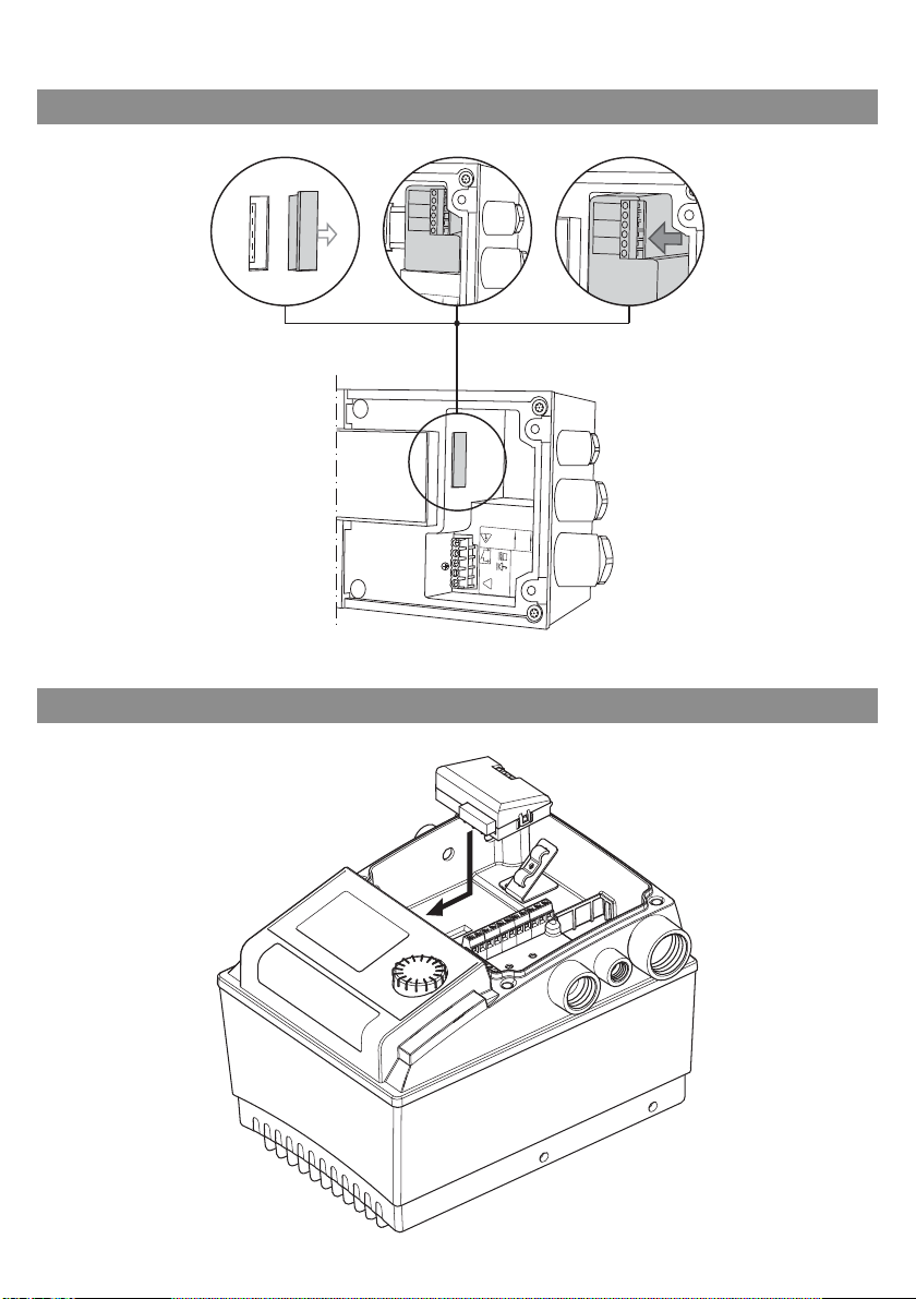
• IF-Modul auf die Platinenschnittstelle stecken:
• Stratos/-D/-Z/-ZD Fig. 3a
• IP-E/DP-E, ... Fig. 3b
• IL-E/DL-E, ... Fig. 3c
• Nicht dargestellte Pumpentypen:
Siehe Einbau- und Betriebsanleitung der jeweiligen Pumpe.
HINWEIS: Damit die in der Einbau- und Betriebsanleitung der Baureihe Stratos
angeführten EMV-Normen eingehalten werden, ist zum Anschluß der Schnittstelle LON ein geschirmtes Kabel zu verwenden.
Um den Schirm dieses Kabels an der Pumpe korrekt aufzulegen, verwenden Sie
die dem IF-Modul Stratos LON beiliegenden metallischen Kabelverschraubungen.
Zur Montage dieser Kabelverschraubung und des entsprechenden Kabels gehen
Sie wie folgt vor (Fig. 4):
Deutsch
Einbau- und Betriebsanleitung Wilo-Control IF-Modul LON / IF-Modul Stratos LON 34
Page 42

Deutsch
• Entfernen Sie die Kunststoff-Kabelverschraubung und die zugehörigen Teile
aus dem Kabeleinführung des Regelmoduls (Fig. 4, Pos.4a)
• Schrauben Sie die metallische Kabelverschraubung in die Kabeleinführung des
Regelmoduls (Fig. 4, Pos.4b)
• Setzen Sie den Kabelaußenmantel des geschirmten Kabels 10...15 mm ab und
klappen Sie den Kabelschirm über den Außenmantel (Fig. 4, Pos.4c).
• Führen Sie das Kabel in die Kabelverschraubung ein, bis der umgeklappte Kabelschirm sicher von den Kontaktfedern gehalten wird (Fig. 4, Pos.4d).
• Schließen Sie die Einzeladern an den Klemmen „LON“ des IF-Moduls an.
HINWEIS:
Die beiden Klemmen „LON“ am IF-Modul sind verdrehsicher, d.h. die Einzeladern
können beliebig an diesen Klemmen angeschlossen werden .
• Ziehen Sie die Überwurfmutter der Kabelverschraubung mit eine m ge ei gne te n
Werkzeug fest (Fig. 4, Pos.4e)
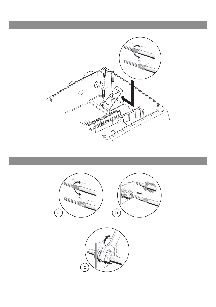
Bei beengten Platzverhältnissen im Klemmenraum der Pumpe kann auch eine
alternative Montage sinnvoll sein:
• Kabel durch Kabelverschraubung führen.
• Einzeladern an den Klemmen des IF-Moduls auflegen (IF-Modul ist noch nicht
gesteckt).
• Einzeladern des Kabels zu einer Schlaufe legen und IF-Modul montieren.
• Klemmenkastendeckel montieren.
8 Inbetriebnahme
VORSICHT!
Bei der Inbetriebnahme ist die Einbau- und Betriebsanleitung der Pumpe zu
beachten.
Die Inbetriebnahme wird stellvertretend für eine Pumpe mit IF-Modul LON
beschrieben. Bei Vorhandensein mehrerer Pumpen mit IF-Modulen LON ist entsprechend zu verfahren.
• Netzspannung der Pumpe(n) einschalten.
• Mit einem Netzwerk-Managementtool oder mit dem Programm „Nodeutil.exe“
der Fa. Echelon wird das IF-Modul LON konfiguriert und online geschaltet.
• Bei der Installation sind die Bindungen der Netzwerkvariablen mit den Netzwerkvariablen anderer Knoten durchzuführen.
• Die für die Installation erforderliche Identifizierung des IF-Moduls LON erfolgt
über den Aufkleber mit dem Code128-Barcode der Neuron-ID. Eine Hälfte des
Aufklebers kann z.B. auf einen Anlagenplan geklebt werden.
• Das IF-Modul LON verwendet Selbstdokumentation, d.h. die Beschreibung der
im IF-Modul enthaltenen Netzwerkvariablen ist im IF-Modul gespeichert und
wird von Netzwerk-Managementtools ausgewertet. Danebe n sind entsprechende XIF- und XFB-Files verfügbar. Die Unterstützung der NetzwerkManagementtools für nicht LonMark-definierte Datentypen erfolgt über
Device-Resource-Files.
35 WILO SE 05/2011
Page 43

• Gemäß den LonMark Application Layer Interoperability Guidelines wird das IFModul LON im Zustand „Application unconfigured“ ausgeliefert. Erhält das IFModul über den LON-Bus ein „Wink“-Kommando, so wird auch in diesem
Zustand ein entsprechendes Kommando zur Pumpe gesendet und an der Pumpe
erscheint das Menü „Id on/off“ für 30 s.
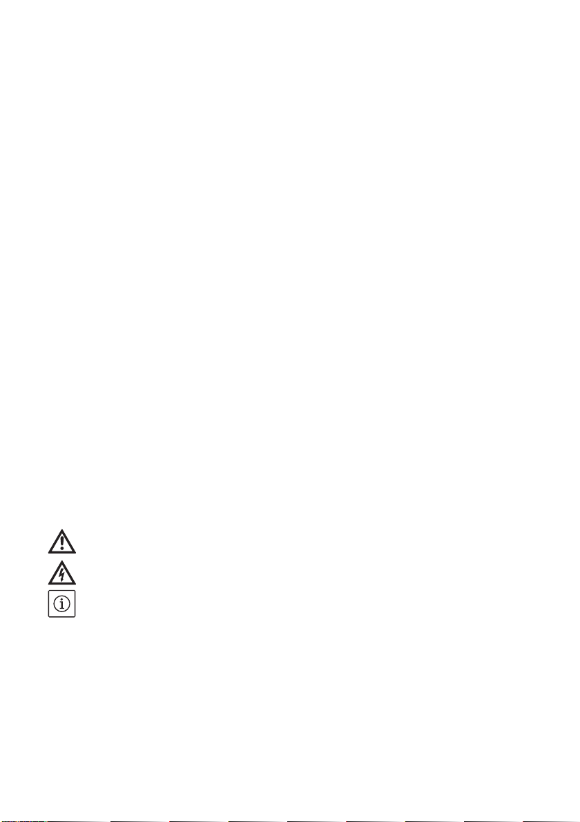
• Das IF-Modul weist einen Taster auf (Fig. 5a/5b, Pos. 2), der mit einem spitzen
Gegenstand (z.B. Kugelschreiber o.ä.) betätigt werden kann. Beim Betätigen
dieses Tasters sendet das IF-Modul eine Netzwerknachricht, in der die NeuronID übertragen wird.
Eine LED (Fig. 5a/5b, Pos. 1) leuchtet bei einem konfigurierten und online
geschalteten IF-Modul nach dem Einschalten der Pumpe oder nach einem Reset
kurz auf.
• Wenn das IF-Modul LON konfiguriert und online geschaltet ist, erscheint im Display der Pumpe ein Doppelpfeil, der bestehende Kommunikation anzeigt. Die
lokale Bedienung an der Pumpe mit dem roten Knopf ist gesperrt.
Ausnahmen:
• Einstellungen für die Doppelpumpenfunktionen Spitzenlast- oder Haupt-/
Reservebetrieb
• Durch Drehen des roten Knopfes gelangen Sie in das Menü „Id“. Durch Drü-
cken des roten Knopfes in diesem Menüpunkt wird eine Netzwerknachricht
gesendet, in der die Neuron-ID übertragen wird.
HINWEIS:
Bei einer Unterbrechung der Spannungsversorgung der Pumpe arbeitet das IFModul LON nicht mehr. Alle Eingangs-Netzwerkvariablen (nvi...) werden beim
Wiedereinschalten auf Ihre Startwerte zurückgesetzt.
Deutsch
9Wartung
Wartungs- und Reparaturarbeiten nur durch qualifiziertes Fachpersonal!
WARNUNG! Gefahr durch Stromschlag!
Gefahren durch elektrische Energie sind auszuschließen.
Bei allen Wartungs- und Reparaturarbeiten ist die Pumpe spannungsfrei zu
schalten und gegen unbefugtes Wiedereinschalten zu sichern.
HINWEIS:
Das IF-Modul LON besitzt einen lösch- und wiederbeschreibbaren Programmspeicher, sodass ein späteres Software-Update über den LON-Bus in diesen
Speicher geladen werden kann.
Bei Austausch eines IF-Moduls LON oder Stratos LON mit einer älteren Software-Version (vor 3.00) ist ein Knotentausch nicht ausreichend. Das Modul hat
eine neue Programm-ID und muss im Projekt neu verknüpft werden.
Einbau- und Betriebsanleitung Wilo-Control IF-Modul LON / IF-Modul Stratos LON 36
Page 44

Deutsch
nvoStatus
nvoMaintenance
nvoPumpStatus
10 Störungen, Ursachen und Beseitigung
10.1 Zusammenhang Wilo-Fehlercodes und Fehlermeldungen LON-Bus
Meldung
electrical_fault
in_alarm
electrical_fault
in_alarm
electrical_fault
in_alarm
in_alarm
in_alarm
in_alarm
in_alarm
in_alarm
electrical_fault
in_alarm
electrical_fault
in_alarm
electrical_fault
in_alarm
electrical_fault
in_alarm
electrical_fault
in_alarm
in_alarm
in_alarm
in_alarm
in_alarm
in_alarm
in_alarm
in_alarm
gesetzte Bits
gesetzte Bits
pump_ctrl.supply_fault
pump_ctrl.device_fault
pump_ctrl.supply_fault
pump_ctrl.service_required
pump_ctrl.device_fault
pump_ctrl.supply_fault
pump_ctrl.device_fault
pump_ctrl.device_fault
pump_ctrl.service_required
pump_ctrl.service_required
pump_ctrl.device_fault
pump_ctrl.device_fault
pump_ctrl.device_fault
pump_ctrl.device_fault
pump_ctrl.service_required
pump_ctrl.service_required
pump_ctrl.device_fault
pump_ctrl.device_fault
pump_ctrl.service_required
pump_ctrl.service_required
pump_ctrl.device_fault
pump_ctrl.device_fault
pump_ctrl.service_required
pump_ctrl.service_required
pump_ctrl.device_fault
pump_ctrl.device_fault
pump_ctrl.device_fault
pump_ctrl.service_required
pump_ctrl.service_required
pump_ctrl.service_required
pump_ctrl.device_fault
pump_ctrl.device_fault
pump_ctrl.device_fault
pump_ctrl.device_fault
pump_ctrl.service_required
pump_ctrl.device_fault
in_alarm
in_alarm
unable_to_measure
in_alarm
pump_ctrl.service_required
pump_ctrl.service_required
pump_ctrl.service_required
pump_ctrl.device_fault
pump_ctrl.device_fault
pump_ctrl.device_fault
in_alarm
pump_ctrl.device_fault
nvoPumpFault
gesetzte Bits
pump_ctrl.sf_voltage_low
pump_ctrl.sf_voltage_high
pump_ctrl.sf_phase
pump_ctrl.df_pump_blocked
pump_ctrl.sf_no_fluid
pump_ctrl.df_pump_blocked
pump_ctrl.df_motor_failure
pump_ctrl.df_motor_temp
pump_ctrl.df_motor_failure
pump_ctrl.df_motor_failure
pump_ctrl.df_motor_failure
pump_ctrl.df_motor_failure
pump_ctrl.df_motor_failure
pump_ctrl.df_sensor_failure
pump_ctrl.df_elect_tempfailure_nf
pump_ctrl.df_elect_tempfailure_nf
pump_ctrl.df_elect_failure_nf
pump_ctrl.df_elect_failure
pump_ctrl.df_elect_failure
pump_ctrl.df_sensor_failure
pump_ctrl.df_sensor_failure
pump_ctrl.df_sensor_failure
pump_ctrl.df_elect_failure
pump_ctrl.df_elect_failure_nf
WILO
Bedeutung
Netz-Unterspannung
Netz-Überspannung
2-Phasenlauf
Blockierung
Leerlauf Motor
Laufr./Rotor schwergängig
Lagerverschleiß
Übertemp. Wicklung
Überlast Motor
Kurz/Erdschluß
Wicklungsschluß
Kontaktfehler / Wicklung offen
Temp.fühler Wicklung offen
Drehzahlsensor defekt
Übertemperatur Modul
Übertemp. Leistungsteil
Zuordnung Modul/Pumpe
Laderelais/PFC defekt
Zwischenkreiselko defekt
Temp.sensor Medium
Ext. Drucksensor defekt
Ext. Schwingungs-sensor defekt
GLT-Timeout
DP-Timeout
WILO
LCD-Code
E04
E05
E06
E10
E11
E12
E16
E20
E21
E23
E24
E25
E26
E27
E30
E31
E34
E36
E37
E38
E40
E41
E50
E52
37 WILO SE 05/2011
Page 45

HINWEIS:
Bei der Fehlerdiagnose sind die Einbau- und Betrieb sa nleitungen der entsprechenden Pumpen zu beachten.
Lässt sich die Betriebsstörung der Pumpe/des IF-Moduls nicht beheben,
wenden Sie sich bitte an das Fachhandwerk oder an die nächstgelegene
Wilo-Kundendienststelle oder Vertretung.
11 Entsorgung
Mit der ordnungsgemäßen Entsorgung und durch sachgerechtes Recycling dieses Produktes werden Umweltschäden und eine Gefährdung der persönlichen
Gesundheit vermieden.
1. Zur Entsorgung des Produktes, sowie Teilen davon, die öffentlichen oder
privaten Entsorgungsgesellschaften in Anspruch nehmen.
2. Weitere Informationen zur sachgerechten Entsorgung werden bei der
Stadtverwaltung, dem Entsorgungsamt oder dort, wo das Produkt erworben
wurde, erteilt.
Technische Änderungen vorbehalten!
Deutsch
Einbau- und Betriebsanleitung Wilo-Control IF-Modul LON / IF-Modul Stratos LON 38
Page 46

English
Installation and operating instructions
1 General
1.1 About this document
The language of the original operat ing instructions is Germ an. All other languages
of these instructions are translations of the original operating instructions.
These installation and operating instructions are an integral part of the product.
They must be kept readily available at the place where the product is installed.
Strict adherence to these instructions is a pr ec o ndit i o n for the prop er use and
correct operation of the product.
These installation and operating instructions correspond to the relevant version
of the product and the underlying safety standards valid at the time of going to
print.
EC declaration of conformity:
A copy of the EC declaration of conformity is a component of these operating
instructions.
If a technical modification is made on the designs named there witho u t our
agreement, this declaration loses its validity.
These Installation and operating instructions are intended as supplement to
the Installation and operating instructions for the pumps connected to the
LON bus.
2Safety
These operating instructions contain basic information which must be adhered
to during installation, operation and maintenance. For thi s reaso n, these operating instructions must, without fail, be read by the service technician and the
responsible specialist/operator before installation and commissioning.
It is not only the general safety instructions listed under the main point "safety"
that must be adhered to but also the special safety instructions with danger
symbols included under the following main points.
2.1 Indication of instructions in the operating instructions
Symbols:
General danger symbol
Danger due to electrical voltage
NOTE: ...
Signal words:
DANGER!
Acutely dangerous situation.
Non-observance results in death or the most serious of injuries.
39 WILO SE 05/2011
Page 47

WARNING!
The user can suffer (serious) injuries. 'Warning' implies that (serious) injury
to persons is probable if this information is disregarded.
CAUTION!
There is a risk of damaging the product/unit. "Caution" implies that damage
to the product is likely if this information is disregarded.
NOTE:
Useful information on handling the product. It draws attention to possible
problems.
Information that appears directly on the product, such as
• Direction of rotation arrow,
• Identifiers for connections,
• Rating plate,
• Warning sticker
must be strictly complied with and kept in legible condition.
2.2 Personnel qualifications
The installation, operating, and maintenance personnel must have the appropriate qualifications for this work. Area of responsibility, terms of reference and
monitoring of the personnel are to be ensured by the operator. If the personnel
are not in possession of the necessary knowledge, they are to be trained and
instructed. This can be accomplished if necessary by the manufacturer of the
product at the request of the operator.
English
2.3 Danger in the event of non-observance of the safety instructions
Non-observance of the safety instructions can result in risk of injury to persons
and damage to the environment and the product/unit. Non observance of the
safety instructions results in the loss of any claims to damages.
In particular, lack of care may lead to problems such as:
• Danger to persons from electrical, mechanical and bacteriological influences,
• Damage to the environment due to leakage of hazardous materials.
• Property damage
• Failure of important product/unit functions.
• Failure of required maintenance and repair procedures.
Installation and operating instructions Wilo-Control IF-module LON / IF-module Stratos LON 40
Page 48

English
2.4 Safety consciousness on the job
The safety instructions included in these installation and operating instructions,
the existing national regulations for accident prevention together with any
internal working, operating and safety regulations of the operator are to be
complied with.
2.5 Safety instructions for the operator
This appliance is not intended for use by persons (including children) with
reduced physical, sensory or mental capabilities, or lack of experience and
knowledge, unless they have been given supervision or instruction concerning
use of the appliance by a person responsible for their safety. Children should be
supervised to ensure that they do not play with the appliance.
• If hot or cold components on the product/the unit lead to hazards, local measures must be taken to guard them against touching.
• Guards protecting against touching moving com ponents (such as the coupling)
must not be removed whilst the product is in operation.
• Leakages (e.g. from the shaft seals) of hazardous fluids (which are explosive,
toxic or hot) must be led away so that no danger to persons or to the environment arises. National statutory provisions are to be complied with.
• Danger from electrical current must be eliminated. Local directives or general
directives [e.g. IEC, VDE etc.] and local power supply companies must be adhered to.
2.6 Safety instructions for installation and maintenance work
The operator must ensure that all installation and maintenance work is carried
out by authorised and qualified personnel, who are sufficiently informed from
their own detailed study of the operating instructions.
Work on the product/unit must only be carried out when at a standstill. It is
mandatory that the procedure described in the installation and operating instructions for shutting down the product/unit be complied with.
Immediately on conclusion of the work, all safety and protective devices must
be put back in position and/or r ec o mm issioned.
2.7 Unauthorised modification and manufacture of spare parts
Unauthorised modification and manufacture of spare parts will impair the safety
of the product/personnel and will make void the manufacturer's declarations
regarding safety.
Modifications to the product are only permissible after consultation with the
manufacturer. Original spare parts and accessories authorised by the manufacturer ensure safety. The use of other parts can nullify the liability from the
results of the usage.
41 WILO SE 05/2011
Page 49

2.8 Improper use
The operating safety of the supplied product is only guaranteed for conventional use in accordance with Section 4 of the operating instructions. The limits
values must on no account fall under or exceed those specified in the catalogue/
data sheet.
3 Transport and interim storage
Inspect the product for transport damage immediately upon arrival. Any transport damage found must be reported to the carrier within the prescribed periods.
CAUTION! Risk of damage to the IF-module!
Risk of damage due to improper handling during transport and storage.
• The IF-modules should be pro tec te d against humidity, frost and mechanical
damage during transport and temporary storage.
• The IF-modules must not be exposed to temperatures outside the range of
- 10 °C to + 70 °C
4 Intended use
The IF-module LON/Stratos LON is used to connect electronically controlled
glandless or glanded pumps to a LON. The pump can be preset with setpoints,
operating modes and data from external sensors, and current operating data
and fault signals can be transferred from the pump via the LON bus.
At the same time the IF-module LON/Stratos LON allows tw o pumps to be connected to form a doublepump via an additional DP interface. This interface is a
separate device. It is not aLON-based interface. That is why the LON bus for the
double pump interface is not put under strain and the slave pump can be
equipped with an inexpensive IF-module PLR.
English
Installation and operating instructions Wilo-Control IF-module LON / IF-module Stratos LON 42
Page 50

English
Connectable pump types
Wilo-IF-Module Stratos LON
for glandless pumps
•Wilo-Stratos
•Wilo-Stratos-D
•Wilo-Stratos-Z
•Wilo-Stratos-ZD
• Additional information: see
www.wilo.de/automation
Wilo-IF-Module LON
for glanded pumps
• Wilo-Stratos GIGA
• Wilo-VeroLine-IP-E/DP-E
• Wilo-VeroTwin-IL-E/DL-E
• Wilo-Economy MHIE
• Wilo-Multivert MVIE (1,1-7,5 kW)
• Wilo-Helix VE
• Wilo-Helix Excel
• Additional information: see
www.wilo.de/automation
Table 4.1
5 Product information
5.1 Type key
Example: Wilo-Control IF-module LON
Control Series designation
Type designation: IF-module LON
IF-module Stratos LON
5.2 Technical specifications
Interface: TP/FT10
Terminal cross-section:
Bus cable: twisted in pairs, shielded
Max. bus cable length:
Program ID (software): 9F:FF:CC:51:14:06:04:05
Software version: 3.00 or higher
2.5 mm²
• 900 m with bus topology with max. 3 m long spur
lines
• 450 m with free topology, with max. 250 m between
2 inter-communicating nodes
43 WILO SE 05/2011
Page 51

5.3 Standards
The IF-module LON complies with the following st andards:
• LonMark Application Layer Interoperability Guidelines Version 3.4
• LonMark Layers 1-6 Interoperability Guidelines Version 3.4
• LonMark node object 0000_20
• LonMark pump controller object 8120_10
• LonMark Resource Files Version 13.04
The entire document can be found online at www.wilo.de/automation.
5.4 Scope of delivery
• IF-module LON or IF-module Stratos LON
• Metal threaded cable connection Pg7 (only for IF-Module Stratos LON)
• Metal threaded cable connection Pg9 (only for IF-Module Stratos LON)
• Installation and operating instructions
• CD with supplementary information
5.4.1 Delivery condition
According to the LonMark Application Layer Interoperability Guidelines, theIFmodule LON is delivered in “application unconfigured” condition.
Inthiscondition, the IF-module LON can be addressed via the LON bus,
buttheapplication which normally establishes the communication with
the pump is notyet in operation. There is therefore no activity yet after
connecting the IF-module LON and switching on the power supply of the pump.
English
6Description and function
6.1 Description of the objects
Two objects, the node object and pump object, are implemented in the IFmodule LON. The node object is used to control individual objects within the
node; errors which occur in the individual objects are also indicated centrally
here.
Fig. 1a shows the node object with the corresponding network variables,
Fig. 1bshows the pump controller object with the corresponding network
variables.
NOTE:
• Double pumps should always be equipped with the integrated double pump
management.
• At double pumps, the IF-module LON is connected to the master.
• If the integrated double pump management is not used for double pumps,
the two drives should be treated as two separate individual pump s. In this case,
two LON IF modules are necessary.
• The control functions apply to the double pump as entire unit.
Installation and operating instructions Wilo-Control IF-module LON / IF-module Stratos LON 44
Page 52

English
6.2 Description of the network variables
6.2.1 Value ranges and resolutions of the input network variables
Data range and
effective
resolution WILO
.object_id: 0 – 1
.object_request:
RQ_NORMAL
RQ_DISABLED
RQ_ENABLE
RQ_UPDATE_STATUS
RQ_REPORT_MASK
RQ_CLEAR_STATUS
.state: 0 – 1
.value: 0.0 – 100.0%
HVAC_AUTO
HVAC_MRNG_WRMUP
HVAC_PRE_COOL
HVAC_ECONOMY
.state: 0 – 1
.value: 0.0 – 100.0%
0 - 100%
Eff. resolution: 0.5%
Range depends on
pump type.
Eff. resol.: 0.981 kPa
Invalid data
-
Default value
-
Resolution
-
-
0xFF
SCPTsetpoint
HVAC_AUTO
-
-
(HVAC_NUL)
.state: 0xFF
0x7FFF
0x7FFF
.state: 0xFF
.value: 0xFF
0x7FFF
0x7FFF
-
0.005 %
0.1 kPa
0 – 3276.6 kPa
Eff. resol.: 0.981 kPa
0x7FFF
0x7FFF
0.1 kPa
-273.1 – 327.6 °C
Eff. resol.: 0.1°C
0x7FFF
0x7FFF
0.01°C
Data range
and units
-
Receive
heartbeat
no
No.
1
Object
0
NVT
SNVT_obj_request
Mand. /
opt.
M
Input
network variable
nviRequest
.state: 0 – 1
.value: 0.0
no
1
1
SNVT_switch
M
nviPumpSetpoint
– 100.0%
enum 0 ... 17
no
2
1
SNVT_hvac_mode
M
nviPumpOpMode
(hvac_t)
.state: 0 – 1
.value: 0.0
... +100.0%
-163.84
no
no
6
7
1
1
SNVT_switch
SNVT_lev_percent
O
O
nviPumpOvdStop
nviOvdSpeed
... +163.83 %
-3276.8
... +3276.6 kPa
no
8
1
SNVT_press
O
nviOvdPress
-3276.8
... +3276.6 kPa
yes
10
1
SNVT_press
O
nviRemotePress
-273.17
... +327.66 °C
yes
12
1
SNVT_temp_p
O
nviRemoteTemp
Table 6.2.1
45 WILO SE 05/2011
Page 53

6.2.2 Value ranges and resolutions of the output network variables
Send when value
changes more
than
Send upon nviRequest:
Range and effective
resolution WILO
Invalid
Data
Resolution
update
invalid_id
invalid_request
disabled
electrical_fault
unable_to_measure
manual_control
-
5 % of nroPump-
Char.pressMax
or 2 % of nroPump-
Char.speedMax resp.,
control mode changes
5 % of
nroPumpChar.pressMax
5 % of
nroPumpChar.flowMax
1 kWh
10 % of max. Power
10 % of max. Power
10 h
/h
3
in_alarm
0 – 100.0%
Res: 0.2%
0x7FFF
0.005 %
Range depends on
Pumptype
0x7FFF
0.1 kPa
Res. :0.981 kPa
Range depends on
Pumptype
Res : 0.1 m
0xFFFF
/h
3
0.01 m
/h
3
0 – 65535 kWh
-
1 kWh
Res: 1 kWh
0 – 6553W
-
0.1 W
Res: min. 1 W
0 – 65.5 kW
-
0.1 kW
Res: 0.1 kW
0 – 65535 h
Res: 10 h
-
1 h
2 % of nroPump-
Char.speedMax
0 – 65535 rpm
Res: min.1 rpm
-
1 rpm
5 °C
immediately
-50 °C – 205°C
Res : min. 0.1 °C
DCM_SPEED_CONST
DCM_PRESS_CONST
DCM_PRESS_COMP
0x7FFF
0xFF
0.01 °C
-
DCM_PRESS_AUTO
DCM_NUL
English
0 – 65535 kWh
0 – 6553.5 W
0 – 6553.5 kW
0 – 65535 h
0 – 65535 rpm
-273.17
– 327.66 °C
ENUM 0 – 29
yes
no
21
1
SNVT_temp_p
O
nvoFluidTemp
(device_c_mode_t)
yes
yes
5
1
SNVT_dev_c_mode
M
nvoControlMode
Data Range
and Units
Min.
Send
Time
Send
Heartbt /
Ack
No.
Obj
NVT
Mand.
Opt.
Output-
Networkvariable
yes
yes
2
0
SNVT_obj_status
M
nvoStatus
no
no
8
0
SNVT_address
O
nnvoFileDirectory
-163.84
– 163.83 %
yes
yes
3
1
SNVT_lev_percent
M
nvoPumpCapacity
-3276.8
– 3276.6 kPa
yes
no
14
1
SNVT_press
O
nvoPressure
0 – 655.34 m
yes
yes
no
no
15
24
1
1
SNVT_flow_p
SNVT_elec_kWh
O
O
nvoFlow
nvoEnergyConsum
yes
yes
no
no
22
23
1
1
SNVT_power
SNVT_power_kilo
O
O
nvo Power
nvoPowerkilo
yes
yes
no
no
18
16
1
1
SNVT_time_hour
SNVT_rpm
O
O
nvoRuntime
nvoSpeed
Table 6.2.2
Installation and operating instructions Wilo-Control IF-module LON / IF-module Stratos LON 46
Page 54

English
Send when value
changes more
than
Range and effective
resolution WILO
Invalid
Data--
Resolution
immediately
service_required
-
immediately
sf_voltage_low
-
immediately
sf_voltage_high
sf_phase
sf_no_fluid
df_motor_temp
df_motor_failure
df_pump_blocked
df_elect_temp
df_elect_failure_nf
df_elect_failure
df_sensor_failure
device_fault
supply_fault
speed_low
speed_high
setpt_out_of_range
local_control
-
-
running
remote_press
remote_temp
immediately
HVAC_AUTO
HVAC_MRNG_WRMUP
HVAC_PRE_COOL
0xFF
-
HVAC_ECONOMY
immediately
immediately
immediately
immediately
immediately
after reset
HVAC_NUL
.state: 0 – 1
.value: 0.0%, 100.0%, 0xFF
Error Codes WILO
Error Codes WILO
device_fault
supply_fault
running
device_fault
supply_fault
running
Pump Type List WILO
.state: 0xFF
0xFFFF
0xFFFF
-
-
-
-
---
-
-
Data Range
and Units
bitset
Min.
Send
Send
Heartbt /
No.
Obj
NVT
Mand.
Opt.OO
Output-
Networkvariable
Time
yes
Acknono
20
1
SNVT_dev_maint
nvoMaintenance
bitset
yes
19
1
SNVT_dev_fault
nvoPumpFault
bitset
yes
yes
13
1
SNVT_dev_status
O
nvoPumpStatus
ENUM 0 – 17
(hvac_t)
yes
yes
4
1
SNVT_hvac_mode
M
nvoEffOpMode
.state: 0 – 1
.value: 0.0-100.0%,
bitset
yes
yes
yes
yes
nonono
173839
1
SNVT_switch
O
nvoPumpOverride
no
40
111
SNVT_count
SNVT_count
SNVT_dev_status
OOO
nvoCurrentErrorM
nvoCurrentErrorS
nvoPumpStatusM
bitset
yes
no
41
1
SNVT_dev_status
O
nvoPumpStatusS
Table 6.2.2, continuation
47 WILO SE 05/2011
yes
no
42
1
SNVT_count
O
nvoPumpType
Page 55

6.2.3 Value ranges and resolutions of the configuration input network variables
Data range and effective
resolution WILO
0–0d17h59m59s
Eff. res: 1 s-0–6553 s
Eff. res: 1 s
0–6553s
Eff. res: 1 s
0–6553 s
Eff. res: 1 s
DCM_SPEED_CONST
DCM_PRESS_CONST
DCM_PRESS_COMP
DCM_PRESS_AUTO
0 – 3276.7 kPa
Eff. res: 0.981 kPa
0 – 3276.7 kPa
Eff. res: 0.981 kPa
-273.1 – 327.6 °C
Eff. res: 0.1°C
-273.1 – 327.6 °C
Eff. res: 0.1°C
.TempMin, .TempMax:
0 – 110 °C
Eff. res: 0.1°C
.PressMin, .PressMax:
0 – 3276.7 kPa
Number
22
17
48
49
52
Object
CPT / NVT
0
SCPTmaxSndT
0
1
SCPTlocation
SCPTmaxRcvTime
1
SCPTmaxSendTime
238
1
1
SCPTminSendTime
SCPTdeviceControlMode
239
240
1
1
SCPTminRemotePressureSetpoint
SCPTmaxRemotePressureSetpoint
243
244
1
1
SCPTminRemoteTempSetpoint
SCPTmaxRemoteTempSetpoint
1
UCPTPressTemp
Eff. res: 0.981 kPa
.state: 0–1
213
1
SCPTsetpoint
English
.value: 0–255
Mandatory /
optional /
user
O
O
O
M
O
Input configuration variable
nciMaxStsSendT
nciLocation
nciRcvHrtBt
O
nciSndHrtBt
nciMinOutTm
nciControlMode
O
O
O
O
U
nciRemMinPress
nciRemMaxPress
nciRemMinTemp
nciRemMaxTemp
nciPressTemp
O
nciSetpPreset
Table 6.2.3
Installation and operating instructions Wilo-Control IF-module LON / IF-module Stratos LON 48
Page 56

English
6.2.4 Value ranges and resolutions of the configuration output network variables
Output
configuration
Mandat./
optional
CPT / NVT Object Number Value
variable
nciDevMajVer O SCPTdevMajVer 0 165 03
nciDevMinVer O SCPTdevMinVer 0 166 00
nroPumpChar M SCPTpumpCharacteristic 1 233 depends on
pumptype
nciObjMajVer O SCPTobjMajVer 1 167 03
nciObjMinVer O SCPTobjMinVer 1 168 00
6.2.5 Description of the network variables
Object request
network input SNVT_obj_request nviRequest
This input network variable triggers various operations concerning the no de and
object status. It consists of 2 bytes, the ID byte and the value byte. The ID byte
indicates the number of the object to which the request applies. The ID value 0
refers to the node object; in this case requests may also affect all other objects.
The ID value 1 refers to the pump-controller object.
Value range
Value Function with ID = 0 Function with ID = 1
RQ_NORMAL Normal operation of all objects Normal operation of pump
controller
RQ_DISABLED Stops all objects Stops the pump controller
RQ_ENABLE Enables the node object Enables the pump controller
RQ_UPDATE_STATUS Updates the node object status
(OR operation for all objects)
RQ_REPORT_MASK Supported node object status
signals (OR operation for all
Updates the pump controller
status
Supported pump controller
status signals
objects)
RQ_CLEAR_STATUS Deletes certain status signals in
all objects
Deletes certain pump
controller status signals
49 WILO SE 05/2011
Page 57

Object status
network output SNVT_obj_status nvoStatus
This output network variable provides status information on the individual
objects. The information is bit-coded. All bits are deleted after a reset.
Value range
Bit Function
invalid_id A non-existent object was addressed.
invalid_request An unknown request was sent.
disabled The object in concern is switched off.
electrical_fault The pump controller object indicates an electrical error.
unable_to_measure The pump control ler object cannot communi cate with the pump.
manual_control The pump controller object is disabled for controlling by the
hardware settings at the pump (ext. off, ext. min, IR monitor)
in_alarm The pump controller object indicates an error.
report_mask Indicates that nvoStatus contains the status mask, i.e. the list of all
supported bits, due to a preceding RQ_REPORT_MASK request.
File Directory Address
network output SNVT_address nvoFileDirectory
This network variable specifies the start address of the configuration file direc-
tory.
Additional information can be found in the LonMark documentation pertaining
to the node object.
English
Installation and operating instructions Wilo-Control IF-module LON / IF-module Stratos LON 50
Page 58

English
Maximum status send time
network input config SNVT_elapsed_tm nciMaxStsSendT
This optional input configuration network variable defines a time cycle in which
the object statuses are automatically updated. The status of the node object is
updated in alternation with that of the pump controller object.
Value range:
0d0h0m0s0ms – 0d17h59m59s999ms (in 1 s increments). The value
0d0h0m0s0ms disables the automatic update function.
Initial value: 0d0h0m0s0ms (automatic update function disabled)
SCPT reference: SCPTmaxSendT (22)
Device major version
network output config unsigned short nciDevMajVer
This optional output configuration network variable provides the high byte of
the module version.
SCPT reference: SCPTdevMajVer (165)
Device minor version
network output config unsigned short nciDevMinVer
This optional output configuration network va ria ble provides the low byte of
the module version.
SCPT reference: SCPTdevMinVer (166)
Location label
network input config SNVT_str_asc nciLocation
This optional input configuration network variable can be used to save
information about the installation location of the pump which goes beyond the
information string stored in the Neuron chip, which only consists of 6 Byte.
Value range
Optional NUL-terminated ASCII string of max. 31 bytes length (incl. NUL)
Default value
ASCII string which only consists of NUL (“\0”)
SCPT reference: SCPT_location (17)
51 WILO SE 05/2011
Page 59

Pump setpoint
Setpoint upper limit
(depending on
manfacturer, pump
and control mode)
Actual setpoint [%]
STOP
X
100%
Pump Setpoint
nviPumpSetpoint
[%]
Setpoint lower limit
(depending on
manufacturer, pump
and control mode)
X = ( Setpoint lower limit / setpoint upper limit ) * 100%
network input SNVT_switch nviPumpSetpoint
English
This input network variable is used to switch the pump on and off and specify
asetpoint.
The network variable consists of a status byte in which the switch-on condition
is transmitted and a value byte in which the setpoint is transmitted.
If a status byte of 0 is set, the pump is switched off. If a status byte of 1 is set,
the switch-on condition depends on the value byte.
If a setpoint of 0% is preset, the pump is switched off. If a setpoint greater than
0% is preset, the pump is switched on if the status byte is 1. The setpoint can
be changed in steps of 0.5%.
If setpoints greater than the upper setpoint limit value are set, they are reduced
to the upper setpoint limit value. Accordingly setpoints below the lower
Installation and operating instructions Wilo-Control IF-module LON / IF-module Stratos LON 52
setpoint limit value are raised to the lower setpoint limit value.
The upper and lower setpoint limit values may change if the pump is operated with
an external sensor (see nviRemotePress, nciRem MinP ress a nd nciRe mMaxPres s).
Page 60

English
Value range
Status Value Function
0 0 – 255 STOP
10 STOP
1 1 – 200 0.5 – 100.0%
1 201 – 255 100.0%
Default value: status = 1, value = 200 = 100.0%. The default value corresponds
to the setting which can be stored in the SCPTsetpoint configuration parameter
in a non-volatile manner.
Requested pump operating mode
network input SNVT_hvac_mode nviPumpOpMode
This input network variable is used to set an operating mode. If an operating
mode is set which is not defined or invalid, the pump remains in the current
mode.
Value range
Value Function Comments
HVAC_AUTO Normal operation Setpoint via nviPumpSetpoint
HVAC_MRNG_WRMUP Warm-up mode Maximum speed
HVAC_PRE_COOL Cooling mode Maximum speed
HVAC_ECONOMY Energy-saving mode Setback operation speed
(pump type specific)
HVAC_NUL Invalid
Default value: HVAC_AUTO
Pump Capacity
network output SNVT_lev_percent nvoPumpCapacity
This output network variable provides the current operating point of the pump
as percentage of the maximum setpoint.
When using an external pressure or temperature sensor, this variable provides
the sensor value as a percentage of the maximum sensor value.
53 WILO SE 05/2011
Page 61

Value range
-163.840% – 163.830% (in 0,02% steps). 163.835% is an invalid value.
Transmission
This value is transmitted automatically if it deviates from the value transmitted
last by more than 5% of the value in nroPumpChar.pressMax (with differential
pressure control) or 2% of the value in nroPumpChar.speedMax (with speed
controller). Furthermore, this value is regularly transmitted if the nciSndHrtBt
configuration input was described with a valid clock. This value is also
transmitted if the control mode has been changed by overriding settings or the
connection of an external sensor.
Transmission frequency
The minimum network variable transmission interval can be set by describing
the nciMinOutTm configuration input with a valid clock.
Preset service type: acknowledged
Effective operating mode
network output SNVT_hvac_mode nvoEffOpMode
This output network variable provides the current operating mode of the pump.
This value corresponds to the setting in the nviPumpOpMode input network
variable, provided a different operating mode has not been forced by local
settings at the pump (ext. off, ext. min or IR monitor).
Value range
Value Function Comments
HVAC_AUTO Normal operation Setpoint via nviPumpSetpoint
HVAC_MRNG_WRMUP Warm-up mode Maximum speed
HVAC_PRE_COOL Cooling mode Maximum speed
HVAC_ECONOMY Energy-saving mode Setback operation speed
(pumptype specific)
HVAC_OFF Offline mode Ext. off or manual operation mode
via IR monitor
HVAC_NUL Invalid
English
Transmission
This value is automatically transmitted whenever a change is made.
Furthermore, this value is transmitted regularly if the nciSndHrtBt configuration
input was described with a valid clock.
Transmission frequency
The minimum network variable transmission interval can be set by describing
the nciMinOutTm configuration input with a valid clock.
Preset service type: acknowledged
Installation and operating instructions Wilo-Control IF-module LON / IF-module Stratos LON 54
Page 62

English
Effective device control mode
network output SNVT_dev_c_mode nvoControlMode
This output network variable provides the current control mode of the pump.
Value range
Value Function
DCM_SPEED_CONST Constant speed mode
DCM_PRESS_CONST Differential pressure constant / pressure constant
DCM_PRESS_COMP Compensated pressure mode
DCM_PRESS_AUTO Temperature-dependent differential pressure
Transmission
This value is automatically transmitted whenever a change is made.
Furthermore, this value is transmitted regularly if the nciSndHrtBt configuration
input was described with a valid clock.
Transmission frequency
The minimum network variable transmission interval can be set by describing
the nciMinOutTm configuration input with a valid clock.
Preset service type: acknowledged
Pump override stop command
network input SNVT_switch nviPumpOvdStop
This optional input network variable provides an overriding switch-on/switch-
off function and is intended for maintenance work, for example. The network
variable consists of a status byte and a value byte.
The “OVDSTOP” setting has priority over the setpoint set in nviPumpSetpoint
and the overriding setpoints set in nviOvdSpeed and nviOvdPress.
An overriding setting is indicated in the nvoPumpOverride output network variable.
Value range
Status Value Function
0 0 – 255 NORMAL
10 NORMAL
1 1 – 255 OVDSTOP
255 0 – 255 Invalid (NORMAL)
Default value: status = 255, value = 255
55 WILO SE 05/2011
Page 63

Override setpoint for speed
network input SNVT_lev_percent nviOvdSpeed
This optional input network variable is used for the overriding setting of a speed
setpoint, e.g. for maintenance work. The value is set as a percentage of the
maximum value of the pump. If a valid range is received, the setpoint set via
nviPumpSetpoint or nviOvdPress is overwritten and speed controller mode
automatically set.
The pump is reset to normal condition by an invalid value in all overriding
nviOvdSpeed and nviOvdPress setpoint settings and a “Normal” setting via
nviPumpOvdStop.
An overriding setting is indicated in the nvoPumpOverride output network variable.
Value range
-163.84% – 163.83% (in 0.005% steps). 163.835% is an invalid value.
Values lower than 0% or higher than 100% are limited accordingly and
nvoPumpStatus.pump_ctrl.setpt_out_of_range is set.
Default value: 163.835%
Override setpoint for pressure
network input SNVT_press nviOvdPress
This optional input network variable is used for the overriding setting of
a differential pressure setpoint, e.g. for maintenance work. The value is set as
a percentage of the maximum value of the pump. If a valid range is received,
the setpoint set via nviPumpSetpoint or nviOvdSpeed is overwritten and the
constant differential pressure control mode is automatically set.
The pump is reset to normal condition by an invalid value in all overriding
nviOvdSpeed and nviOvdPress setpoint settings and a “Normal” setting via
nviPumpOvdStop.
An overriding setting is indicated in the nvoPumpOverride output network variable.
Value range
-3276.8 – 3276.6 kPa (in 0.1 kPa steps). 3276.7 kPa is an invalid value.
Values outside the valid range for the respective pump are limited accordingly
and nvoPumpStatus.pump_ctrl.setpt_out_of_range is set.
Default value: 3276.7kPa
English
Remote pressure sensor input
network input SNVT_press nviRemotePress
This optional input network variable allows an external differential pressure
sensor to be used to control the pump. If a valid value is received, the pump
automatically switches to constant differential pressure control mode.
Controlby means of an external sensor is indicated in the
nvoPumpStatus.pump_ctrl.remote_press network variable.
Installation and operating instructions Wilo-Control IF-module LON / IF-module Stratos LON 56
Page 64

English
The nvoPumpCapacity output network variable then indicates the current actual
sensor value as a percentage of the maximum value of the sensor range.
ThenvoPressure output network variable always provides the actual differential
pressure value determined internally by the pump, which may vary from the
sensor value. This is used to analyse the system behaviour. The differential
pressure setpoint is still preset via the nviPumpSetpoint input network variable if
the nviRemotePress network input variable is used.
If an invalid value is sent to the nviRemotePress input network variable or no value
has been received for longer than defined in nciRcvHrtBt, the pump returns to
internal control and the control mode defined in nciControlMode.
The overriding nviOvdSpeed setpoint input also overrides the control with
external sensor.
nviRemotePress has priority over nviRemoteTemp.
Caution: To ensure stable control, nviRemotePress must be sent every 3 s.
Even in this case, stable control of all pump types cannot be ensured however.
Value range
-3276.8 – 3276.6 kPa (in 0.1 kPa steps). 3276.7 kPa is an invalid value.
Default value: 3276.7 kPa.
Remote temperature sensor input
network input SNVT_temp_p nviRemoteTemp
This optional input network variable allows an external temperature sensor
to be used to control the pump. If a valid value is received, the pump
automatically switches to temperature-dependent differential pressure
control mode. Control by means of an external sensor is indicated in the
nvoPumpStatus.pump_ctrl.remote_temp network variable.
The nvoPumpCapacity output network variable then indicates the current
actual sensor value as a percentage of the upper limit of the sensor range. If an
invalid value is sent to the nviRemoteTemp input network variable or no value
is received for longer than defined in nciRcvHrtBt, the pump returns to internal
control and to the control mode defined in nciControlMode.
The overriding nviOvdSpeed and nviOvdPress setpoint inputs also override
control by means of an external sensor.
nviRemotePress has priority over nviRemoteTemp.
Value range
-273.17 ... +327.66 °C (in 0.01 °C steps). 327.67°C is an invalid value.
Default value: 327.67°C.
57 WILO SE 05/2011
Page 65

Pump status diagnostic information
network output SNVT_dev_status nvoPumpStatus
This output network variable provides bit-coded information about the pump
status.
Value range
Bit Description
device_fault Pump error (see nvoPumpFault for detailed information)
supply_fault Supply error (mains voltage, phase missing, dry run, etc.
See nvoPumpFault for detailed information)
speed_low Lower control limit (pump is running at minimum speed, which
is why the required operating point cannot be achieved)
speed_high Upper control limit (pump is running at maximum speed, which
is why the required operating point cannot be achieved)
setpt_out_of_range Setpoint exceeded/fallen short of
local_control Local operation (by ext. off, ext. min or IR monitor)
running Pump is running
remote_press Control by means of external pressure sensor
remote_temp Control by means of external temperature sensor
Transmission
This value is automatically transmitted whenever a change is made.
Furthermore, this value is transmitted regularly if the nciSndHrtBt configuration
input was described with a valid clock.
Transmission frequency
The minimum network variable transmission interval can be set by describing
the nciMinOutTm configuration input with a valid clock.
Preset service type: acknowledged
English
Pump Pressure
network output SNVT_press nvoPressure
This optional output network variable provides the differential pressure
between the pump flanges determined internally by the pump.
Value range
0 – 3276.6 kPa ( in 0.1 kPa steps). 3276.7 kPa is an invalid value.
Transmission
This value is automatically transmitted if it deviates from the value transmitted
last by more than 5% of the value in nroPumpChar.pressMax.
Installation and operating instructions Wilo-Control IF-module LON / IF-module Stratos LON 58
Page 66

English
Transmission frequency
The minimum network variable transmission interval can be set by describing
the nciMinOutTm configuration input with a valid clock.
Preset service type: unacknowledged
Pump flow
network output SNVT_flow_p nvoFlow
This optional output network variable provides the flow rate determined by
the pump.
Value range
0 - 655.34 m
3
/h (in 0.01 m3/h steps). 655.35 m3/h is an invalid value.
Transmission
This value is automatically transmitted if it deviates from the value transmitted
last by more than 5% of the value in nroPumpChar.flowMax.
Transmission frequency
The minimum network variable transmission interval can be set by describing
the nciMinOutTm configuration input with a valid clock.
Preset service type: unacknowledged
Pump speed
network output SNVT_rpm nvoSpeed
This optional output network variable provides the speed of the pump.
Value range
0 – 65535 rpm (in 1 rpm steps).
Transmission
This value is automatically transmitted if it deviates from the value transmitted
last by more than 5% of the value in nroPumpChar.speedMax.
Transmission frequency
The minimum network variable transmission interval can be set by describing
the nciMinOutTm configuration input with a valid clock.
Preset service type: unacknowledged
59 WILO SE 05/2011
Page 67

Pump override active
network output SNVT_switch nvoPumpOverride
This optional output network variable provides the status of the overriding
settings.
Value range
Status Value Function
00 NORMAL
1200 OVERRIDE
255 0 – 255 Invalid
Transmission
This value is transmitted whenever a change is made.
Transmission frequency
The minimum network variable transmission interval can be set by describing
the nciMinOutTm configuration input with a valid clock.
Preset service type: unacknowledged
Current error master
network output SNVT_count nvoCurrentErrorM
This optional output network variable specifies the current error code of the
master pump.
Value range:
0 - 65534, see Wilo error codes list.
Transmission:
This value is transmitted whenever a change is made.
Transmission frequency:
The minimum network variable transmission interval can be set by describing
the nciMinOutTm configuration input with a valid clock pulse.
Preset service type: unacknowledged
English
Installation and operating instructions Wilo-Control IF-module LON / IF-module Stratos LON 60
Page 68

English
Current error slave
network output SNVT_count nvoCurrentErrorS
This optional output network variable specifies the current error code of the
slave pump.
Value range:
0 - 65534, see Wilo error codes list.
Transmission:
This value is transmitted whenever a change is made.
Transmission frequency:
The minimum network variable transmission interval can be set by describing
the nciMinOutTm configuration input with a valid clock pulse.
Preset service type: unacknowledged
Pump status master
network output SNVT_dev_status nvoPumpStatusM
This output network variable supplies bit coded information relating to the
pump status of the master pump.
Value range:
device_fault = pump fault
see nvoPumpFault for more detailed information)
supply_fault = supply fault
(mains voltage, phase missing, dry running, etc. See nvoPump-
Fault for more detailed information)
running = pump running
Transmission:
This value is automatically transmitted whenever a change is made.
Transmission frequency:
The minimum network variable transmission interval can be set by describing
the nciMinOutTm configuration input with a valid clock pulse.
Preset service type: unacknowledged
61 WILO SE 05/2011
Page 69

Pump status slave
This output network variable supplies bit coded information relating to the
pump status of the slave pump.
Value range:
device_fault = pump fault
see nvoPumpFault for more detailed information)
supply_fault = supply fault
(mains voltage, phase missing, dry running, etc. See nvoPump-
Fault for more detailed information)
running = pump running
Transmission:
This value is automatically transmitted whenever a change is made.
Transmission frequency:
The minimum network variable transmission interval can be set by describing
the nciMinOutTm configuration input with a valid clock pulse.
Preset service type: unacknowledged
Pump Type
network output SNVT_count nvoPumpType
This optional output network variable specifies the current pump type.
Value range:
0 - 65534, see list of Wilo pump types
Transmission:
This value is transmitted whenever a change is made.
Transmission frequency:
The minimum network variable transmission interval can be set by describing
the nciMinOutTm configuration input with a valid clock pulse.
Preset service type: unacknowledged
English
Installation and operating instructions Wilo-Control IF-module LON / IF-module Stratos LON 62
Page 70

English
Runtime
network output SNVT_time_hour nvoRuntime
This optional output network variable provides the operating hours of the
pump, or with double pumps, the time during which at least one pump was
running. The counter is reset to 0 h after 65535 h.
Value range
0 – 65535 h (in 10 h steps), (max. 2730 d or 7.48 a).
Transmission
This value is transmitted whenever a change is made.
Transmission frequency
The minimum network variable transmission interval can be set by describing
the nciMinOutTm configuration input with a valid clock.
Preset service type: unacknowledged
Fault states of the pump
network output SNVT_dev_fault nvoPumpFault
This optional output network variable provides bit-coded error information of
the pump. Errors can be device errors or supply errors.
Value range
Bit Description
sf_voltage_low Supply error, mains voltage too low
sf_voltage_high Supply error, mains voltage too high
sf_phase Supply error, phase missing
sf_no_fluid Supply error, dry running
df_motor_temp Device error, excess motor temperature
df_motor_failure Device error, motor defective
df_pump_blocked Device error, pump blocked
df_elect_temp Device faults, excess temperature
df_elect_failure_nf Device error, electronic error
df_elect_failure Device error, electronics defective
df_sensor_failure Device error, sensor defective
Transmission
This value is transmitted whenever a change is made.
Transmission frequency
The minimum network variable transmission interval can be set by describing
the nciMinOutTm configuration input with a valid clock.
Preset service type: unacknowledged
63 WILO SE 05/2011
Page 71

Maintenance states
network output SNVT_dev_maint nvoMaintenance
This optional output network variable provides bit-coded service information of
the pump.
Value range
service_required = service required
Transmission
This value is transmitted whenever a change is made.
Transmission frequency
The minimum network variable transmission interval can be set by describing
the nciMinOutTm configuration input with a valid clock.
Preset service type: unacknowledged
Fluid temperature
network output SNVT_temp_p nvoFluidTemp
This optional output network variable provides the fluid temperature.
Value range
-273.17 – 327.66 °C (in 0.01 °C steps). 327.67°C is an invalid value.
Transmission
This value is automatically transmitted if it deviates from the value transmitted
last by more than 5 °C.
Transmission frequency
The minimum network variable transmission interval can be set by describing
the nciMinOutTm configuration input with a valid clock.
Preset service type: unacknowledged
English
Power consumption in watts
network output SNVT_power nvoPower
This optional output network variable provides the power consumption of the
pump or, in the event of double pumps, the total power output of the master
and slave.
Value range
0 – 6553,5 W (in 0,1 W steps).
Transmission
This value is automatically transmitted if it deviates from the value transmitted
last by more than 10% of the maximum power consumption of the pump.
Installation and operating instructions Wilo-Control IF-module LON / IF-module Stratos LON 64
Page 72

English
Transmission frequency
The minimum network variable transmission interval can be set by describing
the nciMinOutTm configuration input with a valid clock.
Preset service type: unacknowledged
Power consumption in kW
network output SNVT_power_kilo nvoPowerkilo
This optional output network variable provides the power consumption of the
pump or, in the event of double pumps, the total power output of the master
and slave.
Value range
0 – 6553.5 kW (in 0.1 kW steps).
Transmission
This value is automatically transmitted if it deviates from the value transmitted
last by more than 10% of the maximum power consumption of the pump.
Transmission frequency
The minimum network variable transmission interval can be set by describing
the nciMinOutTm configuration input with a valid clock.
Preset service type: unacknowledged
Energy consumption
network output SNVT_elec_kwh nvoEnergyConsum
This optional output network variable provides the energy consumption of the
pump or, in the case of double pumps, the total energy consumption of the
master and slave. The counter is reset to 0 kWh after 65535 kWh.
Value range
0 – 65535 kWh (in 1 kWh steps).
Transmission
This value is transmitted whenever a change is made.
Transmission frequency
The minimum network variable transmission interval can be set by describing
the nciMinOutTm configuration input with a valid clock.
Preset service type: unacknowledged
65 WILO SE 05/2011
Page 73

Control mode for normal operation
network input config SNVT_dev_c_mode nciControlMode
This optional input network variable defines the control mode for normal operation
of the pump if no external sensors are used and no overriding settings are active.
Value range
Value Function
DCM_SPEED_CONST Constant speed mode
DCM_PRESS_CONST Differential pressure constant / pressure constant
DCM_PRESS_COMP Compensated pressure mode
DCM_PRESS_AUTO Temperature-dependent differential pressure
Default value
DCM_PRESS_COMP
SCPT reference: SCPTdeviceControlMode (238)
PressTemp
network input config UCPTpressTemp nciPressTemp
This WILO-specific input network variable defines the characteristic curve for
the DCM_PRESS_AUTO control mode. This variable is stored in the EEPROM.
If the LON IF-module is connected to a pump with other pump characteristics .
The default values are reset.
Value range
The value range depends on the individual network variable types which are
used in the following data field:
typedef struct
{
SNVT_temp_p TempMin
SNVT_temp_p TempMax
SNVT_press PressMin
SNVT_press PressMax
}
UCPTPressTemp
Default values
TempMin = 50°C
TempMax = 90°C
PressMin = nroPumpChar.pressMax / 2
PressMax = nroPumpChar.pressMax / 2 + 9.8 kPa
SCPT reference: none; implemented as UCPT
English
Installation and operating instructions Wilo-Control IF-module LON / IF-module Stratos LON 66
Page 74

English
Remote pressure sensor minimum value
network input config nciRemMinPress
This optional input configuration network variable defines the lower limit value
of an external differential pressure sensor. This network variable is not currently
assigned any function.
Value range
-3276.8 – 3276.6 kPa (in 0.1 kPa steps). 3276.7 kPa is an invalid value.
Default value
<nciRemMinPress> = 3276.7kPa
SCPT reference: SCPTminRemotePressureSetpoint (239)
Remote pressure sensor maximum value
network input config nciRemMaxPress
This optional input configuration network variable defines the upper limit value
of an external differential pressure sensor. This network variable has an
influence on the relative setpoint settings via nviPumpSetpoint and on the value
supplied by nvoPumpCapacity if the preset value is smaller than
nroPumpChar.pressMax. Larger values are always limited internally to
nroPumpChar.pressMax.
Value range
-3276.8 – 3276.6 kPa (in 0.1 kPa steps). 3276.7 kPa is an invalid value.
Default value
<nciRemMaxPress> = 3276.7 kPa
SCPT reference: SCPTmaxRemotePressureSetpoint (240)
Remote temperature sensor minimum value
network input config nciRemMinTemp
This optional input configuration network variable is currently not assigned to
any function.
Value range
-273.17 – 327.66 °C (in 0.01 °C steps). 327.67°C is an invalid value.
Default value
<nciRemMinTemp> = 327.67°C
SCPT reference: SCPTminRemoteTempSetpoint (243)
67 WILO SE 05/2011
Page 75

Remote temperature sensor maximum value
network input config nciRemMaxTemp
This optional input configuration network variable is currently not assigned to
any function.
Value range
-273.17 – 327.66 °C (in 0.01 °C steps). 327.67°C is an invalid value.
Default value
<nciRemMaxTemp> = 327.67°C
SCPT reference: SCPTmaxRemoteTempSetpoint (244)
Pump Characteristic
network output config nroPumpChar
This output configuration network variable provides a data field with the pump
characteristics.
Value range
The value range depends on the individual network variable types which are
used in the following data field:
typedef struct {
SNVT_rpm speedMax;
SNVT_press pressMax;
SNVT_flow_p flowMax;
} SCPT_PumpCharacteristic;
Default value
The default values depend on the respective pump types.
SCPT reference: SCPTpumpCharacteristic (233)
English
Receive heartbeat
network input config SNVT_time_sec nciRcvHrtBt
This optional input configuration network variable defines a clock for the
reception of the nviRemotePress and nviRemoteTemp network variables. If the
network variables in concern are not updated at least once within the clock
specified here, the pump assumes the default values, i. e. local control until a
valid value is received for nviRemotePress or nviRemoteTemp.
Value range
0.0 – 6553.4 s (in 0.1 s steps). The value 0.0 s switch es off th e recep tion
monitoring function. The invalid value 6553.5 s has the same effect as the value
0.0 s.
Installation and operating instructions Wilo-Control IF-module LON / IF-module Stratos LON 68
Page 76

English
Default value
0.0 s (reception monitoring function switched off)
SCPT reference: SCPTmaxRcvTime (48)
Setpoint preset
This additional input configuration network variable stores the setpoint setting
for the pump (nviPumpSetpoint) in the EEPROM of the IF-module LON in a nonvolatile manner. The pump runs with this value after an interruption to the
power supply until a valid value is set for nviPumpSetpoint via the LON.
Value range
See PumpSetpoint
Default value
Status = 1, value = 200 = 100%.
SCPT reference: SCPTSetpoint (213)
Send heartbeat
network input config SNVT_time_sec nciSndHrtBt
This input configuration network variable defines a clock at which
certain output network variables are automatically sent (nvoPumpCapacity,
nvoEffOpMode, nvoControlMode and nvoPumpStatus). A different network
variable is sent with each clock.
Value range
0.0 – 6553.4 s (in 0.1 s steps). The value 0.0 s switches automatic sending off.
The invalid value 6553.5 s has the same effect as the value 0.0 s.
Default value: 0.0 s (automatic sending switched off)
SCPT reference: SCPTmaxSendTime (49)
Minimum send time
network input config SNVT_time_sec nciMinOutTm
This optional input configuration network variable defines a minimum clock for
the automatic transmission of network variables. The network variables are
normally transmitted automatically if they have changed or if they have been
changed at least by a certain amount. This network variable now has the effect
that two transmission procedures are performed only at the specified interval.
This is used, for example, to reduce the system load. The individual network
variables are sent cyclically.
Value range
0.0 – 6553.4 s (in 0.1 s steps). The value 0.0 s switches off the minimum clock.
The invalid value 6553.5 s has the same effect as the value 0.0 s.
Default value: 0.0 s
SCPT reference: SCPTminSendTime (52)
69 WILO SE 05/2011
Page 77

Object major version
network output config unsigned short nciObjMajVer
This output configuration network variable provides the high byte for the
software version.
SCPT reference: SCPTobjMajVer (167)
Object minor version
network output config unsigned short nciObjMinVer
This output configuration network variable provides the low byte for the
software version.
SCPT reference: SCPTobjMinVer (168)
7 Installation and electrical connection
The installation and electrical connections should be performed only by
skilled staff in compliance with local regulations!
WARNING! Danger of injury!
The existing accident prevention regulations should be observed.
WARNING! Danger from electric shock!
Any hazards from electrical current should be ruled out.
Any local or general directives [e.g. IEC, VDE etc.] and directives of the local
power supply companies should be observed.
English
7.1 Installation and electrical connection of the IF-module
NOTE: The IF-module LON is equipped with a Neuron ID double sticker.
One sticker remains on the IF-module, the other sticker can, for example,
be stuck on the system plan in the position of the corresponding pump.
TheNeuron ID from the system plan can be read in with a barcode scanner
or entered manually during binding.
CAUTION! Risk of damage to the IF-module!
The IF-module LON may only be conneceted or disconneceted if the pump is
electrically isolated.
• Electrically isolate the pump.
• Remove the terminal box cover after undoing the screws.
• Connect the IF-module to the circuit board interface:
• Stratos/-D/-Z/-ZD Fig. 3a
• IP-E/DP-E, ... Fig. 3b
• IL-E/DL-E, ... Fig. 3c
• For pump types that are not represented here:
See the installation and operating instructions for the respective pump.
NOTE: In order to adhere to the EMC standards specified in the installation and
operating instructions for the Stratos series, a shielded cable should be used to
connect the LON interface.
Installation and operating instructions Wilo-Control IF-module LON / IF-module Stratos LON 70
Page 78

English
To apply this cable shield at the pump properly, use the metallic cable
connections supplied with the IF-module Stratos LON .
To install this cable connection and the corresponding cable, proceed as follows
(Fig. 4):
• Remove the plastic cable connection and the corresponding parts fro m the
cable feed of the control module (Fig. 4, pos. 4a).
• Screw the metallic cable connection into the cable feed of the control module
(Fig. 4, pos. 4b).
• Separate 10...15mm of the outer cable sheath of the shielded cable and fold the
cable shield over the outer sheath (Fig. 4, pos. 4c).
• Insert the cable in the cable connection until the folded cable shield is held
securely by the contact springs (Fig. 4, pos. 4d).
• Connect the individual wires to the “LON” terminals of the IF-module.
NOTE: The two “LON” terminals at the IF-module are protected against
twisting, i.e. the individual wires can be connected to any of these terminals.
• Tighten the cap nuts of the cable connection with a suitable tool (Fig. 4, pos. 4e).
If the space in the terminal room of the pump is cramped, an alternative type of
installation may make sense:
• Insert the cable through the cable connection.
• Apply the individual wires to the terminals of the IF-module (IF-module is not
yetconnected).
• Bunch the individual wires of the cable to form a loop and install the IF-module.
• Fit the terminal box cover.
8 Commissioning
CAUTION!
The installation and operating instructions of the pump should be observed
during commissioning.
Commissioning is described by the example of a pump with IF-module LON.
If there are several pumps with IF-module LON, proceed accordingly.
• Switch on the mains voltage of the pump(s).
• A network management tool or the “Nodeutil.exe” program from Echelon is
used to configure the IF-module LON and switch it online.
• The network variables should be linked to the network variables of other nodes
during the installation.
• The identification of the IF-module LON required for the installation is performed
with the sticker with the 128 barcode of the Neuron ID. One half of the sticker can
be stuck onto the system plan for example.
• The IF-module LON uses self documentation, i.e. the description of the netw ork
variables contained in the IF-module is stored in the IF-module and evaluated
by network management tools. Furthermore, corresponding XIF and XFB files
are available. The network management tools for non-LonMark-defined data
types are supported by device-resource files.
71 WILO SE 05/2011
Page 79

• According to the LonMark Application Layer Interoperability Guidelines, the IFmodule LON is delivered in “application unconfigured” condition. If the IFmodule receives a “wink” command via the LON bus, a corresponding command
is sent to the pump also in this condition and the “Id on/off” menu is displayed
at the pump for 30 s.
• The IF-modul has a button (Fig. 5a/5b, pos. 2) which can be operated with a
pointed object (e.g. a ballpoint pen). When this button is actuated, the IFmodule sends a network message in which the Neuron ID is transmitte d.
An LED (Fig. 5a/5b, pos.1) goes on briefly if the IF-module is configured and
switched online after switching on the pump or after a reset.
• Once the LON IF-module has been configured and switched online, a double
arrow appears on the pump display (Fig. 6, pos. 1) to indicate the existing
communication. Local operation of the pump with the red button is disabled.
Exceptions:
• Settings for the peak load or main/standby operation double pump functions
• You can access the “Id” menu by turning the red button. A network message
is sent in which the Neuron ID is trans mitted by pressing the red button in this
menu item.
NOTE: The IF-module LON no longer works if there is an interruption to the
power supply of the pump. All input network variables (nvi...) are reset to their
default values when the power supply is switched on again.
9 Maintenance
Have maintenance and repair work carried out by qualified skilled
personnel only!
WARNING! Danger from electric shock!
Any danger from electrical current should be ruled out.
The pump should be electrically isolated and secured against unauthorised
switch-on during any maintenance or repair work.
NOTE: The IF-module LON has a program memory which can be deleted and
overwritten to allow subsequent software updates to be loaded into this
memory via the LON bus.
If an IF-Module LON or Stratos LON is replaced with an older software version
(prior to 3.00), a node replacement is not sufficient. The module has a new program ID and a new link must be created within the project.
English
Installation and operating instructions Wilo-Control IF-module LON / IF-module Stratos LON 72
Page 80
English
nvoStatus
nvoMaintenance
nvoPumpStatus
10 Faults, causes and remedies
10.1 Connection between WILO error codes and LON bus fault signals
Meldung
electrical_fault
in_alarm
electrical_fault
in_alarm
electrical_fault
in_alarm
in_alarm
in_alarm
in_alarm
in_alarm
in_alarm
electrical_fault
in_alarm
electrical_fault
in_alarm
electrical_fault
in_alarm
electrical_fault
in_alarm
electrical_fault
in_alarm
in_alarm
in_alarm
in_alarm
in_alarm
in_alarm
in_alarm
in_alarm
gesetzte Bits
gesetzte Bits
pump_ctrl.supply_fault
pump_ctrl.device_fault
pump_ctrl.supply_fault
pump_ctrl.service_required
pump_ctrl.device_fault
pump_ctrl.supply_fault
pump_ctrl.device_fault
pump_ctrl.device_fault
pump_ctrl.service_required
pump_ctrl.service_required
pump_ctrl.device_fault
pump_ctrl.device_fault
pump_ctrl.device_fault
pump_ctrl.device_fault
pump_ctrl.service_required
pump_ctrl.service_required
pump_ctrl.device_fault
pump_ctrl.device_fault
pump_ctrl.service_required
pump_ctrl.service_required
pump_ctrl.device_fault
pump_ctrl.device_fault
pump_ctrl.service_required
pump_ctrl.service_required
pump_ctrl.device_fault
pump_ctrl.device_fault
pump_ctrl.device_fault
pump_ctrl.service_required
pump_ctrl.service_required
pump_ctrl.service_required
pump_ctrl.device_fault
pump_ctrl.device_fault
pump_ctrl.device_fault
pump_ctrl.device_fault
pump_ctrl.service_required
pump_ctrl.device_fault
in_alarm
in_alarm
unable_to_measure
in_alarm
pump_ctrl.service_required
pump_ctrl.service_required
pump_ctrl.service_required
pump_ctrl.device_fault
pump_ctrl.device_fault
pump_ctrl.device_fault
in_alarm
pump_ctrl.device_fault
nvoPumpFault
gesetzte Bits
pump_ctrl.sf_voltage_low
pump_ctrl.sf_voltage_high
pump_ctrl.sf_phase
pump_ctrl.df_pump_blocked
pump_ctrl.sf_no_fluid
pump_ctrl.df_pump_blocked
pump_ctrl.df_motor_failure
pump_ctrl.df_motor_temp
pump_ctrl.df_motor_failure
pump_ctrl.df_motor_failure
pump_ctrl.df_motor_failure
pump_ctrl.df_motor_failure
pump_ctrl.df_motor_failure
pump_ctrl.df_sensor_failure
pump_ctrl.df_elect_tempfailure_nf
pump_ctrl.df_elect_tempfailure_nf
pump_ctrl.df_elect_failure_nf
pump_ctrl.df_elect_failure
pump_ctrl.df_elect_failure
pump_ctrl.df_sensor_failure
pump_ctrl.df_sensor_failure
pump_ctrl.df_sensor_failure
pump_ctrl.df_elect_failure
pump_ctrl.df_elect_failure_nf
WILO
Bedeutung
Netz-Unterspannung
Netz-Überspannung
2-Phasenlauf
Blockierung
Leerlauf Motor
Laufr./Rotor schwergängig
Lagerverschleiß
Übertemp. Wicklung
Überlast Motor
Kurz/Erdschluß
Wicklungsschluß
Kontaktfehler / Wicklung offen
Temp.fühler Wicklung offen
Drehzahlsensor defekt
Übertemperatur Modul
Übertemp. Leistungsteil
Zuordnung Modul/Pumpe
Laderelais/PFC defekt
Zwischenkreiselko defekt
Temp.sensor Medium
Ext. Drucksensor defekt
Ext. Schwingungs-sensor defekt
GLT-Timeout
DP-Timeout
WILO
LCD-Code
E04
E05
E06
E10
E11
E12
E16
E20
E21
E23
E24
E25
E26
E27
E30
E31
E34
E36
E37
E38
E40
E41
E50
E52
73 WILO SE 05/2011
Page 81

NOTE:
The installation and operating instructions for the respective pumps should be
observed during error diagnostics.
If the pump/IF-module malfunction is unable to be rectified, please contact
a specialist or the nearest Wilo customer service or representative.
11 Disposal
Proper disposal and recycling of this product prevents damage to the environment and risks to personal health.
1. Use public or private waste management companies for the disposal of the
product or components.
2. For more information on the correct disposal, please contact your local
council or waste disposal office or the supplier from whom you obtained the
product.
We reserve the right to make technical changes.
English
Installation and operating instructions Wilo-Control IF-module LON / IF-module Stratos LON 74
Page 82

Page 83

WILO SE
Nortkirchenstraße 100
44263 Dortmund
Germany
T +49 231 4102-0
F +49 231 4102-7363
wilo@wilo.com
www.wilo.com
Algeria
Bad Ezzouar, Dar El Beida
T +213 21 247979
chabane.hamdad@
salmson.fr
Armenia
0001 Yerevan
T +374 10 544336
info@wilo.am
Bosnia and
Herzegovina
71000 Sarajevo
T +387 33 714510
zeljko.cvjetkovic@
wilo.ba
Georgia
0179 Tbilisi
T +995 32 306375
info@wilo.ge
Macedonia
1000 Skopje
T +389 2 3122058
valerij.vojneski@wilo.c
om.mk
Mexico
07300 Mexico
T +52 55 55863209
roberto.valenzuela@wi
lo.com.mx
Moldova
2012 Chisinau
T +373 22 223501
sergiu.zagurean@
wilo.md
Rep. Mongolia
Ulaanbaatar
T +976 11 314843
wilo@magicnet.mn
Tajikistan
734025 Dushanbe
T +992 37 2312354
info@wilo.tj
Turkmenistan
744000 Ashgabad
T +993 12 345838
kerim.kertiyev@wilotm.info
Uzbekistan
100015 Tashkent
T +998 71 1206774
info@wilo.uz
March 2011
Wilo – International
(Subsidiaries)
Wilo – International
(Representation offices)
Argentina
WILO SALMSON
Argentina S.A.
C1295ABI Ciudad
Autónoma de Buenos
Aires
T+ 54 11 4361 5929
info@salmson.com.ar
Austria
WILO Pumpen
Österreich GmbH
2
351 Wiener Neudorf
T +43 507 507-0
office@wilo.at
Azerbaijan
WILO Caspian LLC
1014 Baku
T +994 12 5962372
info@wilo.az
Belarus
WILO Bel OOO
220035 Minsk
T +375 17 2535363
wilo@wilo.by
Belgium
WILO SA/NV
1083 Ganshoren
T +32 2 4823333
info@wilo.be
Bulgaria
WILO Bulgaria Ltd.
1125 Sofia
T +359 2 9701970
info@wilo.bg
Canada
WILO Canada Inc.
Calgary, Alberta T2A 5L4
T +1 403 2769456
bill.lowe@wilo-na.com
China
WILO China Ltd.
101300 Beijing
T +86 10 58041888
wilobj@wilo.com.cn
Croatia
WILO Hrvatska d.o.o.
10090 Zagreb
T
+38 51 3430914
wilo-hrvatska@wilo.hr
Czech Republic
WILO Praha s.r.o.
25101 Cestlice
T +420 234 098711
info@wilo.cz
Denmark
WILO Danmark A/S
2690 Karlslunde
T +45 70 253312
wilo@wilo.dk
Estonia
WILO Eesti OÜ
12618 Tallinn
T +372 6 509780
info@wilo.ee
Finland
WILO Finland OY
02330 Espoo
T +358 207401540
wilo@wilo.fi
France
WILO S.A.S.
78390 Bois d'Arcy
T +33 1 30050930
info@wilo.fr
Great Britain
WILO (U.K.) Ltd.
DE14 2WJ BurtonUpon-Trent
T +44 1283 523000
sales@wilo.co.uk
Greece
WILO Hellas AG
14569 Anixi (Attika)
T +302 10 6248300
wilo.info@wilo.gr
Hungary
WILO Magyarország Kft
2045 Törökbálint
(Budapest)
T +36 23 889500
wilo@wilo.hu
India
WILO India Mather and
Platt Pumps Ltd.
Pune 411019
T +91 20 27442100
service@
pun.matherplatt.co.in
Indonesia
WILO Pumps Indonesia
Jakarta Selatan 12140
T +62 21 7247676
citrawilo@cbn.net.id
Ireland
WILO Engineering Ltd.
Limerick
T +353 61 227566
sales@wilo.ie
Italy
WILO Italia s.r.l.
20068 Peschiera
Borromeo (Milano)
T +39 25538351
wilo.italia@wilo.it
Kazakhstan
WILO Central Asia
050002 Almaty
T +7 727 2785961
info@wilo.kz
Korea
WILO Pumps Ltd.
621-807 Gimhae
Gyeongnam
T +82 55 3405890
wilo@wilo.co.kr
Latvia
WILO Baltic SIA
1019 Riga
T +371 7 145229
mail@wilo.lv
Lebanon
WILO SALMSON
Lebanon
12022030 El Metn
T +961 4 722280
wsl@cyberia.net.lb
Lithuania
WILO Lietuva UAB
03202 Vilnius
T +370 5 2136495
mail@wilo.lt
The Netherlands
WILO Nederland b.v.
1551 NA Westzaan
T +31 88 9456 000
info@wilo.nl
Norway
WILO Norge AS
0975 Oslo
T +47 22 804570
wilo@wilo.no
Poland
WILO Polska Sp. z.o.o.
05-090 Raszyn
T +48 22 7026161
wilo@wilo.pl
Portugal
Bombas Wilo-Salmson
Portugal Lda.
4050-040 Porto
T +351 22 2080350
bombas@wilo.pt
Romania
WILO Romania s.r.l.
077040 Com. Chiajna
Jud. Ilfov
T +40 21 3170164
wilo@wilo.ro
Russia
WILO Rus ooo
123592 Moscow
T +7 495 7810690
wilo@wilo.ru
Saudi Arabia
WILO ME - Riyadh
Riyadh 11465
T +966 1 4624430
wshoula@wataniaind.com
Serbia and
Montenegro
WILO Beograd d.o.o.
11000 Beograd
T +381 11 2851278
office@wilo.co.yu
Slovakia
WILO Slovakia s.r.o.
83106 Bratislava
T +421 2 33014511
wilo@wilo.sk
Slovenia
WILO Adriatic d.o.o.
1000 Ljubljana
T +386 1 5838130
wilo.adriatic@wilo.si
South Africa
Salmson South Africa
1610 Edenvale
T +27 11 6082780
errol.cornelius@
salmson.co.za
Spain
WILO Ibérica S.A.
28806 Alcalá de
Henares (Madrid)
T +34 91 8797100
wilo.iberica@wilo.es
Sweden
WILO Sverige AB
35246 Växjö
T +46 470 727600
wilo@wilo.se
Switzerland
EMB Pumpen AG
4310 Rheinfelden
T +41 61 83680-20
info@emb-pumpen.ch
Taiwan
WILO-EMU Taiwan Co.
Ltd.
110 Taipeh
T +886 227 391655
nelson.wu@
wiloemutaiwan.com.tw
Turkey
WILO Pompa Sistemleri
San. ve Tic. A.S¸.
34888 Istanbul
T +90 216 6610211
wilo@wilo.com.tr
Ukraina
WILO Ukraina t.o.w.
01033 Kiew
T +38 044 2011870
wilo@wilo.ua
United Arab Emirates
WILO Middle East FZE
Jebel Ali Free Zone South
- Dubai
T +971 4 880 91 77
info@wilo.ae
USA
WILO USA LLC
1290 N 25
th
Ave
Melrose Park, Illinois
60160
T +1 866 945 6872
info@wilo-usa.com
Vietnam
WILO Vietnam Co Ltd.
Ho Chi Minh City,
Vietnam
T +84 8 38109975
nkminh@wilo.vn
Page 84

WILO SE
Nortkirchenstraße 100
44263 Dortmund
Germany
T 0231 4102-0
F 0231 4102-7363
wilo@wilo.com
www.wilo.de
Nord
WILO SE
Vertriebsbüro Hamburg
Beim Strohhause 27
20097 Hamburg
T 040 5559490
F 040 55594949
hamburg.anfragen@wilo.com
Nord-Ost
WILO SE
Vertriebsbüro Berlin
Juliusstraße 52–53
12051 Berlin-Neukölln
T 030 6289370
F 030 62893770
berlin.anfragen@wilo.com
Ost
WILO SE
Vertriebsbüro Dresden
Frankenring 8
01723 Kesselsdorf
T 035204 7050
F 035204 70570
dresden.anfragen@wilo.com
Süd-Ost
WILO SE
Vertriebsbüro München
Adams-Lehmann-Straße 44
80797 München
T 089 4200090
F 089 42000944
muenchen.anfragen@wilo.com
Süd-West
WILO SE
Vertriebsbüro Stuttgart
Hertichstraße 10
71229 Leonberg
T 07152 94710
F 07152 947141
stuttgart.anfragen@wilo.com
Mitte
WILO SE
Vertriebsbüro Frankfurt
An den drei Hasen 31
61440 Oberursel/Ts.
T 06171 70460
F 06171 704665
frankfurt.anfragen@wilo.com
West
WILO SE
Vertriebsbüro Düsseldorf
Westring 19
40721 Hilden
T 02103 90920
F 02103 909215
duesseldorf.anfragen@wilo.com
Kompetenz-Team
Gebäudetechnik
WILO SE
Nortkirchenstraße 100
44263 Dortmund
T 0231 4102-7516
T 01805 R•U•F•W•I•L•O*
7•8•3•9•4•5•6
F 0231 4102-7666
Kompetenz-Team
Kommune
Bau + Bergbau
WILO SE, Werk Hof
Heimgartenstraße 1-3
95030 Hof
T 09281 974-550
F 09281 974-551
Werkskundendienst
Gebäudetechnik
Kommune
Bau + Bergbau
Industrie
WILO SE
Nortkirchenstraße 100
44263 Dortmund
T 0231 4102-7900
T 01805 W•I•L•O•K•D*
9•4•5•6•5•3
F 0231 4102-7126
kundendienst@wilo.com
Täglich 7-18 Uhr erreichbar
24 Stunden Technische
Notfallunterstützung
– Kundendienst-
Anforderung
– Werksreparaturen
– Ersatzteilfragen
– Inbetriebnahme
– Inspektion
– Technische
Service-Beratung
– Qualitätsanalyse
Wilo-International
Österreich
Zentrale Wiener
Neudorf:
WILO Pumpen Österreich
GmbH
Max Weishaupt Straße 1
A-2351 Wiener
Neudorf
T +43 507 507-0
F +43 507 507-15
Vertriebsbüro Salzburg:
Gnigler Straße 56
5020 Salzburg
T +43 507 507-13
F +43 507 507-15
Vertriebsbüro
Oberösterreich:
Trattnachtalstraße 7
4710 Grieskirchen
T +43 507 507-26
F +43 507 507-15
Schweiz
EMB Pumpen AG
Gerstenweg 7
4310 Rheinfelden
T +41 61 83680-20
F +41 61 83680-21
Standorte weiterer
Tochter gesellschaften
Argentinien,
Aserbaidschan, Belarus,
Belgien, Bulgarien, China,
Dänemark, Estland,
Finnland, Frankreich,
Griechenland,
Großbritannien, Indien,
Indonesien, Irland, Italien,
Kanada, Kasachstan, Korea,
Kroatien, Lettland, Libanon,
Litauen, Niederlande,
Norwegen, Polen, Portugal,
Rumänien, Russland,
Saudi-Arabien, Schweden,
Serbien und Montenegro,
Slowakei, Slowenien,
Spanien, Südafrika, Taiwan,
Tschechien, Türkei,
Ukraine, Ungarn, USA,
Vereinigte Arabische
Emirate, Vietnam
Die Adressen finden Sie
unter www.wilo.com.
Stand August 2010
Wilo-Vertriebsbüros in Deutschland
Erreichbar Mo–Fr von 7–18 Uhr.
– Antworten auf
– Produkt- und Anwendungsfragen
– Liefertermine und Lieferzeiten
– Informationen über Ansprechpartner vor Ort
– Versand von Informationsunterlagen
* 0,14 €/Min. aus dem Festnetz,
Mobilfunk max. 0,42 €/Min.
 Loading...