

Wilo Drain TM 32, Drain TMW 32, Drain TMR 32 Installation And Operating Instructions Manual
Page 1
Pioneering for You
Wilo-Drain TM 32, TMW 32, TMR 32
de Einbau- und Betriebsanleitung
en Installation and operating instructions
fr Notice de montage et de mise en service
nl Inbouw- en bedieningsvoorschriften
el Οδηγίεςεγκατάστασηςκαιλειτουργίας
tr Montajvekullanmakılavuzu
2 036 885-Ed.07 / 2015-06-Wilo
sv Monterings- och skötselanvisning
da Monterings- og driftsvejledning
hu Beépítésiésüzemeltetésiutasítás
pl Instrukcjamontażuiobsługi
ru Инструкцияпомонтажуиэксплуатации
lt Montavimo ir naudojimo instrukcija
Page 2
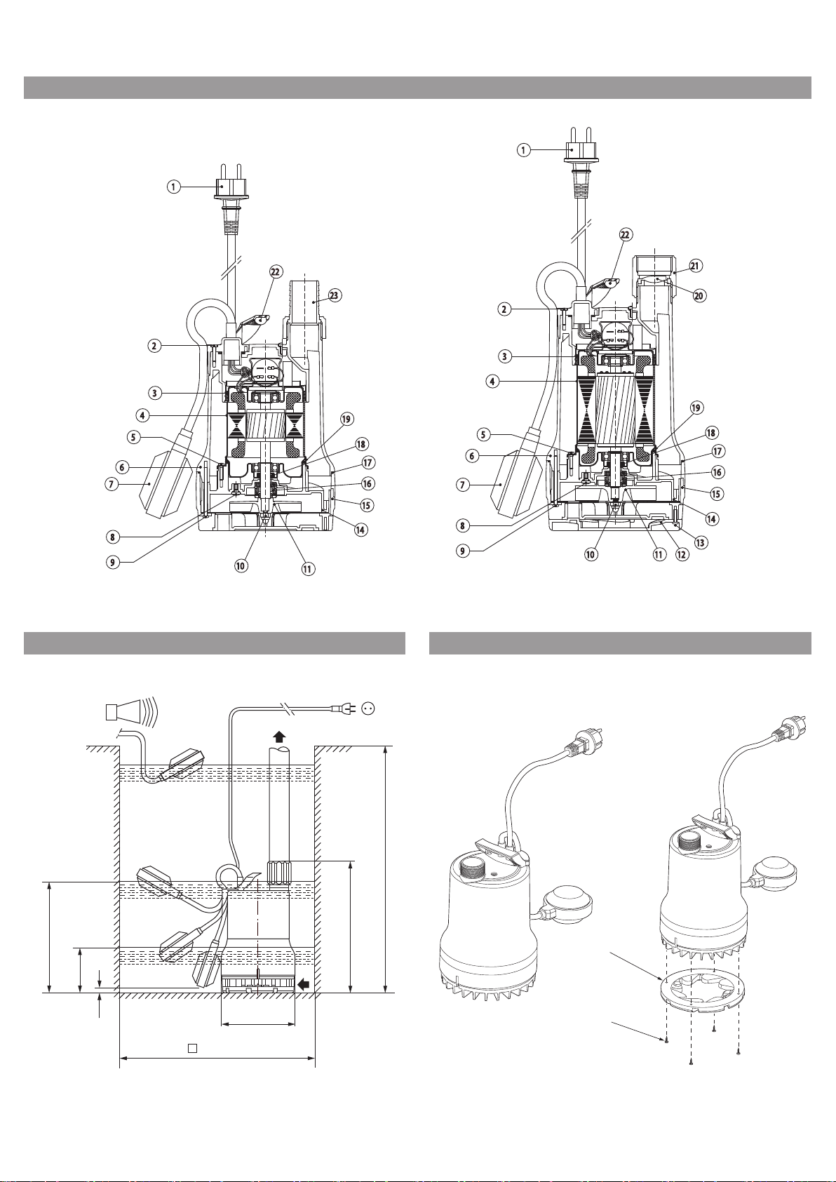
Fig. 1:
Fig. 2: Fig. 3:
1~230 V, 50 Hz
min
H
h
1
h
2
h
D
L
23 WMT23 RMT / 23 MT
1
2
B
min
Page 3
English
Installation and operating instructions
1 General
About this document
The language of the original operating instructions is French. All other languages of these
instructions are translations of the original operating instructions.
These installation and operating instructions are
an integral part of the product. They must be kept
readily available at the place where the product is
installed. Strict adherence to these instructions is
a precondition for the proper use and correct
operation of the product.
These installation and operating instructions correspond to the relevant version of the product and
the underlying safety standards valid at the time
of going to print.
EC declaration of conformity:
A copy of the EC declaration of conformity is a
component of these operating instructions.
If a technical modification is made on the designs
named there without our agreement, this declaration loses its validity.
2 Safety
These operating instructions contain basic information which must be adhered to during installation and operation. For this reason, these
operating instructions must, without fail, be read
by the service technician and the responsible
operator before installation and commissioning.
It is not only the general safety instructions listed
under the main point “safety” that must be
adhered to but also the special safety instructions
with danger symbols included under the following
main points.
2.1 Indication of instructions in the operating
instructions
Symbols:
General danger symbol
Danger due to electrical voltage
USEFUL INFORMATION
Signal words:
DANGER!
Acutely dangerous situation
Non-observance results in death or the most
serious of injuries.
WARNING!
The user can suffer (serious) injuries. 'Warning'
implies that (serious) injury to persons is probable if this information is disregarded.
CAUTION!
There is a risk of damaging to the product/
installation. 'Caution' implies that damage to the
product is likely if the information is disregarded.
NOTE: Useful information on handling the product. It draws attention to possible problems.
2.2 Personnel qualifications
The installation personnel must have the appropriate qualifications for this work.
2.3 Danger in the event of non-observance of the
safety instructions
Non-observance of the safety instructions can
result in risk of injury to persons and damage to
product/installation. Non-observance of the
safety instructions can result in the loss of any
claims for damages.
In detail, non-observance can, for example, result
in the following risks:
• Failure of important functions of the product/
installation,
• Failure of specified maintenance and repair procedures,
• Risks to persons through electrical, mechanical
and bacteriological effects,
• Property damage.
2.4 Safety instructions for the operator
The existing directives for accident prevention
must be adhered to. Danger from electrical current
must be eliminated. Local directives or general
directives [e.g. IEC, VDE etc.] and local power supply companies must be adhered to.
This appliance is not intended for use by persons
(including children) with reduced physical, sensory
or mental capabilities, or lack of experience and
knowledge, unless they have been given supervision or instruction concerning use of the appliance
by a person responsible for their safety.
Children should be supervised to ensure that they
do not play with the appliance.
2.5 Safety instructions for inspection and
installation work
The operator must ensure that all inspection and
installation work is carried out by authorised and
qualified personnel, who are sufficiently informed
from their own detailed study of the operating
instructions.
Work to the product/installation must only be carried out when at a standstill. It is mandatory that
the procedure described in the installation and
operating instructions for shutting down the
product/unit be complied with.
Installation and operating instructions Wilo-Drain TM/TMW/TMR 9
Page 4
English
2.6 Unauthorised modification and manufacture of
spare parts
Modifications to the product are only permissible
after consultation with the manufacturer. Original
spare parts and accessories authorised by the
manufacturer ensure safety. The use of other
parts can nullify the liability from the results of
their usage.
2.7 Improper use
The operational safety of the supplied product is
only guaranteed for conventional use in accordance with section 4 of the installation and operating instructions. The limit values must on no
account fall under or exceed those specified in the
catalogue/data sheet.
3 Transport and interim storage
As soon as the product arrives:
• Check the product for damage in transit,
• In the case of transport damage, initiate the necessary procedures with the forwarding agent
within the time stipulated.
CAUTION! Danger of property damage!
Incorrect transport and incorrect intermediate
storage can lead to product damage.
• The pump may only be suspended/carried by the
strap provided for transport purposes. The cable
should never be used for lifting!
• The pump must be protected against moisture,
frost and mechanical damage when transported
and stored.
The pumps are usually installed under water (submerged) and can only be permanently or transportably installed vertically. Because of the sheath
current cooling, the pumps can also be operated
unsubmerged.
Submersible pumps with a mains connection cable
of less than 10 metres are (according to EN 60335)
only permitted for use inside buildings, i.e. not for
operating outside.
Pumps that are intended for use in or at garden
ponds or similar places must have a mains connecting cable that is not lighter than rubber
sheathed cables reference H07 RN-F (245 IEC 66)
according to EN 60335.
Danger! Mortal danger due to electric shock
The pump many not be used to drain swimming
pools / garden ponds or similar places if anyone
is in the water.
WARNING! Hazardous to health!
Owing to the materials used, the pumps are not
suitable for potable water! Unpurified foul and
waste water represents a health hazard.
CAUTION! Danger of property damage!
Pumping unpermitted substances can lead to
product damage.
The pumps are not suitable for water with
coarse contamination such as sand, fibres or
combustible, caustic fluids or for use in potentially explosive areas.
Correct use of the product also includes following
these instructions.
Any use over and beyond these is interpreted as
incorrect use.
4 Intended use
The Drain TM series drainage and submersible
waste water pumps are used:
• for the automatic drainage of pits and shafts,
• for keeping dry yard areas and basement rooms
exposed to flooding,
• for lowering surface water,
if the waste water is not able to flow off into the
sewer system through natural fall.
The pumps are suitable for pumping slightly contaminated water, rainwater, drainage water and
washing water.
TMR pumps versions are intended for pumping
down to 2 mm suction level from the floor. This
version is recommended for mobile installation
and pumping clear water.
5.2 Technical data
Mains voltage: 1~230 V, ± 10 %
Mains frequency: 50 Hz
Protection class: IP 68
Insulation class: 155
Speed: 2900 rpm (50 Hz)
Max. current consumption: See name plate
Power consumption P1: See name plate
Max. flow rate: See name plate
Max. delivery head: See name plate
Operating mode S1: 200 operating hours a year
Example: TM 32/8 -10M
TM Submersible pump
W W = with whirl system (TWISTER function)
32 Nominal diameter of pressure port [mm]:
/8 Max. delivery head [m] when Q = 0m³/h
HD For aggressive water
10M Length of mains connecting cable [m]: 10
5 Product information
5.1 Type key
TMW 32/11 HD
R = low suction version
32 = Rp 1¼
(material 1.4435 (AISI316L))
10 WILO SE 06/2015
Page 5
5.2 Technical data
Operating mode S3 (optimum):
Recommended switching frequency:
Intermittent duty, 25 % (2.5 min. operation, 7.5 min. interval).
20/h
Max. switching frequency: 50/h
Free ball passage: 10 mm (Model TMR: 2 mm)
Nominal diameter of the pressure port:
Ø 32 mm (Rp 1¼),
grooved hose connector Ø 35 mm supplied with TM32/7 and TM32/8-10M
Admissible fluid temperature:
briefly 3 min.:
Max. submersion depth :
Flat suction up to: 14 mm (Model TMR: 2 mm)
Maximum fluid density: 1060 kg/m
+3 to 35 °C
90 °C
4 m connecting cable = 1 m - 10 m connecting cable = 3 m
3
English
5.3 Scope of delivery
Pump with
• 4 m connecting cable with mains plug
(Model TM ... 10M: 10 m)
• Connected float switch
(except TM32/8-10M)
• Whirl self cleaning system (TWISTER function)
for TMW
• Pressure port Rp 1¼
(Model TM32/7 and TM32/8-10M: grooved hose
connector Ø 35 mm)
• Non-return valve
(except TM32/7 and TM32/8-10M)
• Installation and operating instructions
5.4 Accessories
Accessories must be ordered separately
(see catalogue):
• Switchgear for 1 or 2 pump operation
• Alarm switchgear AlarmControl with mini float
switch and plug
• External monitoring devices / tripping unit
• Level control (e.g. flow switch)
• Accessories for transportable wet sump installa-
tion (e.g. hose couplings, hoses, etc.).
• Accessories for stationary wet sump installation
(e.g. check valves, non-return valves, etc.)
The use of new accessories is recommended.
6 Description and function
6.1 Description of the product (Fig. 1)
Pos. Description of the
component
Cable 13 Screw
1
Screw 14 Diffusor
2
O-ring 15 Strainer
3
Motor housing 16 Mechanical seal
4
Screw 17 O-ring
5
External housing 18 Rotary shaft seal
6
Float swich 19 O-ring
7
Screw 20 Non-return valve
8
Screw 21 Pressure port Rp 1¼
9
Nut 22 Handle
10
Impeller 23 Grooved hose connector
11
Whirl system
12
(TWISTER function)
Pos. Description of the
component
The pump can be completely submerged in the
fluid.
The electric motor is protected against the pump
chamber by a rotary shaft seal to seal the motor
against the oil chamber and a mechanical seal to
seal the oil chamber against the fluid. The
mechanical seal chamber is filled with medical
white oil so that the mechanical seal is lubricated
and cooled during a dry run. A further rotary shaft
seal protects the mechanical seal facing the fluid.
The motor is cooled by the surrounding fluid.
The pump is installed on the floor of a shaft. For a
stationary installation, it is bolted to a fixed pres-
sure pipe or for a transportable installation, it is
connected to a hose connection.
The pumps are commissioned by plugging in the
protective contact plug.
They operate automatically, when the float switch
switches the pump on from a certain water level
“h” (Fig. 2) and switches it off at a minimum water
level “h1”.
The motors are equipped with thermal motor protection, which switches off the motor automatically if it overheats and switches it on again when
it has cooled down. The condenser is integrated in
the single-phase motor.
Version with whirl system (TWISTER function)
For waste water with precipitating and floating
particles, the submersible pump has been
equipped with a whirl system at the suction
strainer. Precipitating particles are continuously
whirled up in the suction area of the pump and
pumped off with the water. Therefore, mud accumulation in the pump shaft, with problematic
consequences such as clogging of the pump and
odour formation, is largely prevented.
If the removal of the waste water does not allow
any interruption, a second pump (automatic
standby pump), together with the necessary
switchgear (accessory), increases the operating
reliability if the 1st pump develops a fault.
Installation and operating instructions Wilo-Drain TM/TMW/TMR 11
Page 6

English
7 Installation and electrical connection
DANGER! Risk of fatal injury!
Incorrect installation and improper electrical
connections can result in a risk of fatal injury.
• The installation and electrical connections
should only be done by properly skilled staff and
in compliance with the applicable regulations!
• Follow all accident prevention regulations!
7.1 Installation
The pump is designed for stationary or transportable installation.
CAUTION! Danger of property damage!
Danger of damage due to incorrect handling.
Only suspend the pump by the strap with the aid
or a chain or rope, never by the electrical or float
switch cable or the pipe/hose connection.
The installation site or shaft for the pump must be
free of frost.
The shaft must be cleared of coarse material such
as rubble before setting up and starting the pump.
The quality of the shaft must guarantee the
unhindered mobility of the float switch.
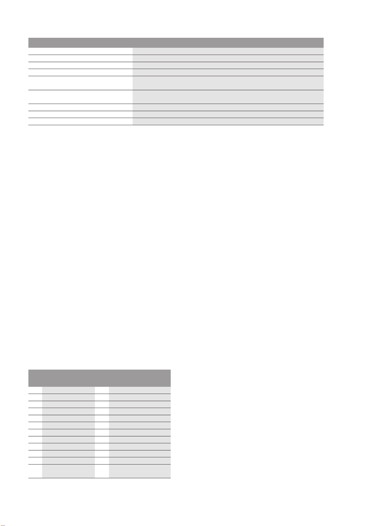
Installation dimension / shaft dimensions
(cf. Fig 2)
Pump H
TM 32/7
TM 32/8
TM 32/11
Pump h
TM 32/7
TM 32/8
TM 32/11
The diameter of the pressure pipe (pipe/hose connection) should not be smaller than the pressure
connection of the pipe because of the increased
risk of clogging and greater pressure losses. To
avoid pressure losses, it is recommended that the
pipe connection one number higher is selected.
min
B
min
[mm]
280 350 x 350 294 165
280 350 x 350 293 165
330 350 x 350 323 165
max
h1
min
[mm]
237 50 14
250 50 14
280 50 14
L D
h2
min
• Seal the pipe connections to the pressure port
with Teflon tape.
NOTE: Permanent leakage in this area can lead to
destruction of the non-return valve and of the
screwed connection.
Transportable wet sump installation
In the case of a transportable wet sump installation with hose connection, the pump must be
secured in the shaft to prevent it from falling over
and wandering (e.g. secure chain / rope with slight
pre-tension).
NOTE: When used in a sump without a firm base,
the pump must be put on a sufficiently large plate
or hung from a rope or a chain in a suitable position.
7.2 Electrical connection
DANGER! Risk of fatal injury!
If the electrical connection is not made properly,
there is a risk of fatal injury from electric shock.
Only allow the electrical connection to be made
by an electrician approved by the local electricity supplier and in accordance with the local regulations in force.
• The type of mains connection current and voltage
must correspond to the details on the name plate
• Fuse in the power supply: 10 A, slow,
• Earth the installation according to the regulations.
• The installation of a leakage current protection
switch to be provided on site for a trip current of
30 mA is recommended (caution when installing
outside).
• The pump is ready to connect.
To connect the pump to the switchgear, the
shock-proof plug is disconnected and the connecting cable is then connected as follows (see
Installation and operating instructions for the
switchgear):
3-wire connection cable: 3x1.0 mm
Conductor Terminal
brown L1
blue
green/yellow
N
PE
²
Stationary wet sump installation
In the case of a stationary wet sump installation of
Socket and switchgear must be installed in a dry
room and protected against flooding.
the pump with a permanent pressure pipe, the
pump must be positioned and secured so that:
• The pressure pipe connection does not support
the weight of the pump.
• The load of the pressure pipe does not act on the
connecting socket.
• The pump is installed stress-free.
To protect against any backflow from the public
drainage pipe, the pressure pipe must be taken in
an arc over the locally established backflow level
(usually street level). A non-return valve does not
represent a guaranteed backflow seal.
• The attached non-return valve should be installed
8 Commissioning
DANGER! Danger through electric shock!
The pump may not be used to drain swimming
pools / garden ponds or similar place if anyone is
in the water.
CAUTION! Danger of property damage!
Do not allow the mechanical seal to run dry!
Dry running shortens the service life of the
motor and the mechanical seal. If the mechanical
seal is damaged, small amounts of oil may
escape into the pumped fluid.
if the pump is installed permanently.
12 WILO SE 06/2015
Page 7

English
• When filling the shaft or lowering the pump into
the pit, make sure that the float switches can
move freely. The switch must switch off the pump
before the intake openings of the pump can draw
in air.
• After filling the shaft and opening the check valve
on the pressure side (if provided), the pump starts
up automatically when the switch-on level “h” is
reached and switches off as soon as the switchoff level “h1” responds.
• Do not direct the jet of water to be fed into the
shaft at the suction strainer of the pump.
Entrained air can prevent the operating pump
from functioning if the vent slit in the housing is
blocked.
• The maximum volume of water entering the shaft
must not exceed the performance of the pump.
Keep an eye on the shaft when commissioning the
pump.
NOTE: The venting of the pump when commissioned for the first time will be improved by submersion in the fluid at an angle or by positioning it
at a slight angle.
Adjusting the switching level of the float switch
The perfect functioning of the level control system is guaranteed if the details according to the
table in 7.1 and Fig. 2 are observed.
The switching level (switch-on/off point) can be
changed via the free float switch cable by moving
the cable within the clip on the pump handle. The
level “h2 min” must be respected (see Fig. 2).
On version TMR, to reach the maximum low suction level, the float switch must be manually lifted.
A small degree of water evacuation (lateral slit
between suction strainer and housing) when level
“h2” is reached is normal and necessary to ensure
the operational safety of the pump.
• Do not direct the jet of water to be fed into the
shaft at the suction strainer of the pump.
Entrained air can prevent the operating pump
from functioning if the vent slit in the housing is
blocked.
• The maximum quantity of water feeding into the
shaft may not exceed the pump's capacity. Monitor the sump during commissioning.
• To increase the required capacity (by approx.16%
of the delivery head) the whirl system device of
the TMW pump can be shut down as follows
(fig. 3):
• Pull the mains plug,
• Remove pump from the sump,
• Remove the 4 screws (pos. 2) below the suction
basket,
• Remove the whirl device (pos. 1), rotate by 180°
and secure again with the 4 screws,
• Lower pump again and start up.
9 Maintenance
Maintenance and repairs may only be carried out
by qualified experts!
DANGER! Risk of fatal injury!
There is a mortal danger through shock when
working on electrical equipment.
• Before any maintenance and repair work, the
pump must be switched off and prevented from
being switched on again in an unauthorised
manner.
• Damage to the connecting cable may only be
repaired by a qualified electrical contractor in
principle.
• When checking the function following long
downtimes, avoid contact with the fluid.
In order to prevent blockage of the pump resulting
from long downtimes, its ability to function should
be checked at regular intervals (every 2 months)
by manual raising of the float switch or direct
switching-on and brief start-up of the pump.
Minor wear of the rotary shaft seal and mechanical
seal can lead to fouling of the liquid following an
oil leak from the oil chamber.
The pump should therefore be serviced after
approx. 2000 operating hours by a specialist or
Wilo After-sales Service, mainly in order to check
the seals.
Only specialist companies or Wilo After-sales
Service may open the encapsulated motor.
Cleaning the pump
Depending on the use of the pump, fouling can
occur within the suction strainer and the impeller.
Rinse off he pump under running water after use.
1 Switch off the power supply. Disconnect the
mains plug.
2 Drain the pump
TMW:
3 The whirl device is screwed to the suction
strainer (fig. 3).
• Loosen 4 screws (∅3.5 x 14),
• Remove whirl device,
4 The suction strainer is screwed to the pump
housing,
• Loosen 4 screws (∅4 x 60),
• Remove suction strainer, handle O-ring
(∅155 x 2) between suction strainer / pump
housing and O-ring (∅14 x 2) in the bypass
hole (necessary for the whirl function) with
care.
TM/TMR:
4 The suction strainer is screwed to the pump
housing,
• Loosen 4 screws (∅4 x 60),
• Remove suction strainer, handle O-ring
(∅155 x 2) between suction strainer / pump
housing with care.
5 Clean the impeller and pump housing under
running water. The impeller must turn freely.
6 Replace damaged or worn parts with original
spares.
7 Re-assembly the pump in the reverse order.
Installation and operating instructions Wilo-Drain TM/TMW/TMR 13
Page 8

English
10 Faults, causes and remedies
Only have faults remedied by qualified personnel!
Observe safety instructions in 9 Maintentance.
Fault Cause Remedy
The pump does not start or stops
during operation
Pump does not switch on/off
Pump does not pump
Flow rate drops during operation
Current supply interrupted Check fuses, cables and electrical
connections.
Motor protection switch has tripped Allow the pump to cool down, it will start
again automatically
Fluid temperature too high Allow to cool down
Pump silted up or blocked Disconnect the pump from the mains and
remove from the shaft.
Remove the suction strainer and rinse the
suction strainer / impeller under running
water
Float switch blocked or cannot move freely Check float switch and ensure mobility
Air in the installation cannot escape Place the pump at an angle in water briefly
until the air escapes.
Vent the installation / drain if necessary
Dismantle suction strainer / whirl device,
rinse suction strainer / vent slit under run-
ning water.
Check the switch-off level “h1”
Water level below the intake port If possible, submerge the pump deeper
(observe the switch-off level)
Pressure pipe / hose diameter too small
(losses too high)
Non-return valve sticking in the pressure
port
Hose kinked / check valve closed Clear kink in hose / open check valve
Suction strainer blocked / impeller blocked Disconnect the pump from the mains and
Bigger dimensioning of the pressure pipe /
hose diameters
Check function
remove from the shaft.
Remove the suction strainer and rinse the
suction strainer / impeller under running
water.
If the fault cannot be remedied, please contact
the trade or your nearest Wilo-After-sales
Service or agent.
11 Spare parts
Spares should be ordered through local trade outlets and/or the Wilo-After-sales Service.
To avoid queries and incorrect orders, all the data
on the name plate must be indicated when ordering.
Subject to change without prior notice!
14 WILO SE 06/2015
Page 9

Page 10

(BG) - български език (CS) - Čeština
ДЕКЛАРАЦИЯ ЗА СЪОТЕТСТВИЕ EO ES PROHLÁŠENÍ O SHODĚ
(DA) - Dansk (EL) - Ελληνικά
De er ligeled es i overensstemmelse med de harmo niserede europæis ke
και επίσης με τα εξής εναρμονισμένα ευρωπαϊκά πρότυπα που αναφέρονται
(ES) - Español (ET) - Eesti keel
(FI) - Suomen kieli (HR) - Hrvatski
Lisäksi ne ovat seuraavien edellisellä sivulla mainittujen
i usklađenim europskim normama navedenim na prethodnoj stranici.
(HU) - Magyar (IT) - Italiano
EK-MEGFELELŐSÉGI NYILATKOZAT DICHIARAZIONE CE DI CONFORMITÀ
(LT) - Lietuvių kalba (LV) - Latviešu valoda
(MT) - Malti (NL) - Nederlands
DIKJARAZZJONI KE TA’ KONFORMITÀ EG-VERKLARING VAN OVEREENSTEMMING
preċedenti.
De producten voldoen eveneens aan de geha rmoniseerde Europes e normen
F_GQ_013-05
приелите ги национални законодателства:
předpisům, které je přejímají:
las legislaciones nacionales que les son aplicables :
seadusandlustega, mis ni metatud direktiivid üle o n v õ tnud:
termékek megfelelnek a következő európai irányelvek előírásainak, valamint
azok nemzeti jogrendbe átültet et t ren d elkezéseinek:
legislazioni nazionali che le traspongono :
WILO SE декларират, че продуктите посочени в настоящата декларация
съответстват на разпоредбите на следните европейски директиви и
Hиско Hапрежение 2006/95/ЕО ; Електромагнитна съвместимост
2004/108/ЕО
както и на хармонизираните европейски стандарти, упоменати на
предишната страница.
EF-OVERENSSTEMMELSESERKLÆRING ΔΗΛΩΣΗ ΣΥΜΜΟΡΦΩΣΗΣ EK
WILO SE erklærer, at produkterne, s om beskrives i denne erklæring, er i
overensstemm else med bestemmelserne i følg ende europæiske direktiver,
samt de natio n ale lovgivninger, der gennemfø re r dem:
Lavspændings 2006/95/EF ; El ek trom ag neti s k K o m p atibilitet 2004/108/EF
standarder, der er anført på forrige side.
DECLARACIÓN CE DE CONFORMIDAD EÜ VASTAVUSDEKLARATSIOONI
WILO SE declara que los produc to s c itados en la presenta declaración están
conformes con las disposiciones de las siguientes directivas europeas y con
Baja Tensión 2006/95/CE ; Compatibilidad Electromagnética 2004/108/CE
Y igualmente están conformes con las disposi ci ones de las normas europeas
armonizadas citadas en la página anterior.
WILO SE prohlašuje, že výrobky uvedené v tomto prohlášení odpovídají
ustanovením níže uvedených evropských směrnic a národním právním
Nízké Napětí 2006/95/ES ; Elektromagnetická Kompatibilita 2004/108/ES
a rovněž splňují požadavky harmonizovaných evropských norem uvedených
na předcházející stránce.
WILO SE δηλώνει ότι τα προϊόντα που ορίζονται στην παρούσα ευρωπαϊκά
δήλωση είναι σύμφωνα με τις διατάξεις των παρακάτω οδηγιών και τις
εθνικές νομοθεσίες στις οποίες έχει μεταφερθεί:
Χαμηλής Tάσης 2006/95/ΕΚ ; Ηλεκτρομαγνητικής συμβατότητας
2004/108/ΕΚ
στην προηγούμενη σελίδα.
WILO SE kinnitab, et selles vastavustunnistuses kirjeldatud to o ted o n
kooskõlas alljärgnevate Euroopa direktiivide sätetega ning riiklike
Madalpingeseadmed 2006/95/EÜ ; Elektromagnetilist Ühilduvust
2004/108/EÜ
Samuti on tooted kooskõlas eelmisel leheküljel ära toodud harmoniseeritud
Euroopa standarditega.
EY-VAATIMUSTENMUKAISUUSVAKUUTUS EZ IZJAVA O SUKLADNOSTI
WILO SE vakuuttaa, että tässä vakuutuksess a k uv atut tuo tteet ov at
seuraavien eurooppalaisten direktiivien määräysten sekä niihin
sovellettavien kansallisten lakiasetusten mukaisia:
Matala Jännite 2006/95/EY ; Sähköma gneettinen Yhteensopivuus
2004/108/EY
yhdenmukaistettujen euroo p p alaisten normien mukaisia.
WILO SE kijelenti, hogy a jelen megfelelőségi nyilatkozatban megjelölt
Alacsony Feszültségű 2006/95/EK ; Elektromágneses összeférhetőségre
2004/108/EK
valamint az előző oldalon szereplő, harmonizált európai szabványoknak. E sono pure conformi alle disposizioni delle norme europee armonizzate
WILO SE izjavljuje da su proizvodi navedeni u ovoj izjavi u skladu sa
sljedećim prihvaćenim europskim direktivama i nacionalnim zakonima:
Smjernica o niskom napo nu 2006/ 95/ EZ ; Elektromagnetna kompatibil no s t -
smjernica 2004/108/EZ
WILO SE dichiara che i prodotti descritti nella presente dichiarazione sono
conformi alle disposizioni delle seguenti direttive europee nonché alle
Bassa Tensione 2006/95/CE ; Compatibil ità Elettromagnetica 2004/108/CE
citate a pagina precedente.
EB ATITIKTIES DEKLARACIJA EK ATBILSTĪBAS DEKLARĀCIJU
WILO SEdeklarē, ka izstrādājumi, kas ir nosaukti šajā deklarācijā, atbilst
WILO SE pareiškia, kad šioje deklaracijoje nurodyti gaminiai atitinka šių
Europos direktyvų ir jas perkeliančių nacionalinių įstatymų nuostatus:
Žema įtampa 2006/95/EB ; Elektromagnetinis Suderinamumas 2004/108/EB Zemsprieguma 2006/95/EK ; Elektromagnētiskās Saderības 2004/108/EK
šeit uzskaitīto Eiropas direktīvu nosacījumiem, kā arī atsevišķu valstu
likumiem, kuros tie ir ietverti:
ir taip pat harmonizuo tas Europ as no rm as , k urios buvo cituotos
ankstesniame puslapyje.
WILO SE jiddikjara li l-prodotti speċifikati f’din id-dikjarazzjoni huma
konformi mad-direttivi Ewropej li jsegwu u mal-leġislazzjonijiet nazzjonali li
japplikawhom:
Vultaġġ Baxx 2006/95/KE ; Kompatibbiltà Elettromanjetika 2004/108/KE
kif ukoll man-normi Ewropej armoniżżati li jsegwu imsemmija fil-paġna
un saskaņotajiem Eiropas standartiem, kas minēti iepriekšējā lappusē.
WILO SE verklaart dat de in deze v e rklaring vermelde producten voldoen
aan de bepali ngen van de volgende Eu ropese richtli j n en e venals aan de
nationale w et g evingen waarin deze bepalingen zijn overgenomen:
Laagspannings 2006/95/EG ; El ek tro m ag netische Compatibilitei t
2004/108/EG
die op de vorige pagina worden genoemd.
Page 11

(NO) - Norsk (PL) - Polski
EU-OVERENSSTEMMELSESERKLAEING DEKLARACJA ZGODNOŚCI WE
(PT) - Português (RO) - Română
E obedecem também às normas europeias harmonizadas citadas na página
şi, de asemenea, sunt conforme cu normele europene armonizate citate în
(RU) - русский язык (SK) - Slovenčina
(SL) - Slovenščina (SV) - Svenska
pa tudi z usklajenimi evropskih standardi, navedenimi na prejšnji strani.
Det överensstämmer även med följ a nde harmoniserade europeiska
(TR) - Türkçe
CE UYGUNLUK TEYID BELGESI
F_GQ_013-05
ulusal kanunlara uygun olduğunu beyan etmektedir:
med følgend e e ur o peiske direktiver og nasjonal e lover:
transponującymi je przepisami prawa krajowego:
национальным предписаниям:
odpovedajúcich národných legislatívnych predpisov:
WILO SE erklærer at produktene nevnt i denne erklærin g en er i samsvar
WILO SE oświadcza, że produkty wymienione w niniejszej deklaracji są
zgodne z postanowieniami następujących dyrektyw europejskich i
EG–Lavspenningsdirektiv 2006/95/ EG ; EG–EMV–El ektro m agnetisk
kompatibili tet 2004/108/ EG
og harmonis er t e eu ropeiske standard er nevnt på forrige side. oraz z nastepującymi normami europejskich zharmonizowanymi podanymi
Niskich Napięć 2006/95/WE ; Kompatybilności Elektromagnetycznej
2004/108/WE
na poprzedniej stronie.
DECLARAÇÃO CE DE CONFORMIDADE DECLARAŢIE DE CONFORMITATE CE
WILO SE declara que os materiais designados na presente declaração
obedecem às disposições das directivas europeias e às legislações nacionais
que as transcrevem :
Baixa Voltagem 2006/95/CE ; Com p atibilidade Electromagnética
2004/108/CE
precedente.
WILO SE declară că produsele citate în prezenta declaraţie sunt conforme cu
dispoziţiile directivelor europene următoare şi cu legislaţiile naţionale care le
transpun :
Joasă Tensiune 2006/95/CE ; Compatibilitate Electromagnetică 2004/108/CE
pagina precedentă.
Декларация о соответствии Европейским нормам ES VYHLÁSENIE O ZHODE
WILO SE заявляет, что продукты, перечисленные в данной декларации
о соответствии, отвечают следующим европейским директивам и
Директива ЕС по низковольтному оборудованию 2004/95/ЕС ; Директива
ЕС по электромагнитной совместимости 2004/108/ЕС
и гармонизированным европейским стандартам, упомянутым на
предыдущей странице.
WILO SE čestne prehlasuje, že výrobky ktoré sú predmetom tejto
deklarácie, sú v súlade s požiadavkami nasledujúcich európskych direktív a
Nízkonapäťové zariadenia 2006/95/ES ; Elektromagnetickú Kompatibilitu
2004/108/ES
ako aj s harmoniz o vanými európskych normami uvedenými na
predchádzajúcej strane.
ES-IZJAVA O SKLADNOSTI EG-FÖRSÄKRAN OM ÖVERENSSTÄMMELSE
WILO SE izjavlja, da so izdelki, navedeni v tej izjavi, v skladu z določili
naslednjih evropskih direktiv in z nacionalnimi zakonodajami, ki jih
vsebujejo:
Nizka Napetost 2006/95/ES ; Elektro m ag netno Združljivostjo 2004/108/ES
WILO SEbu belgede belirtilen ürünlerin aşağıdaki Avrupa yönetmeliklerine ve
Alçak Gerilim Yönetmeliği 2006/95/AT ; Elektromanyetik Uyumluluk
Yönetmeliği 2004/108/AT
ve önceki sayfada belirtilen uyumlaştırılmış Avrupa standartlarına.
WILO SE intygar att materialet s o m b es k rivs i följande intyg
överensstämm er med bestämmels er na i följande europ eiska direktiv och
nationella lagstiftningar som inför dem:
Lågspännings 2006/95/EG ; Elektromagneti s k K o m p atibilitet 2004/108/EG
standarder som nämnts på den föregående sid an.
Page 12

Page 13

Page 14

Page 15

Wilo – International (Subsidiaries)
Argentina
WILO SALMSON
ArgentinaS.A.
C1295ABI Ciudad
Autónoma de Buenos Aires
T+ 54 11 4361 5929
info@salmson.com.ar
Australia
WILO Australia Pty Limited
Murrarrie, Queensland,
4172
T +61 7 3907 6900
chris.dayton@wilo.com.au
Austria
WILO Pumpen
ÖsterreichGmbH
2351 Wiener Neudorf
T +43 507 507-0
office@wilo.at
Azerbaijan
WILO Caspian LLC
1014 Baku
T +994 12 5962372
info@wilo.az
Belarus
WILO Bel OOO
220035 Minsk
T +375 17 2535363
wilo@wilo.by
Belgium
WILO SA/NV
1083Ganshoren
T +32 2 4823333
info@wilo.be
Bulgaria
WILOBulgariaLtd.
1125 Sofia
T +359 2 9701970
info@wilo.bg
Brazil
WILO Brasil Ltda
Jundiaí – São Paulo – Brasil
ZIPCode:13.213-105
T +55 11 2923 (WILO)
9456
wilo@wilo-brasil.com.br
Canada
WILOCanadaInc.
Calgary, Alberta T2A 5L4
T +1 403 2769456
bill.lowe@wilo-na.com
China
WILOChinaLtd.
101300 Beijing
T +86 10 58041888
wilobj@wilo.com.cn
Croatia
WiloHrvatskad.o.o.
10430 Samobor
T +38 51 3430914
wilo-hrvatska@wilo.hr
Czech Republic
WILOCS,s.r.o.
25101Cestlice
T +420 234 098711
info@wilo.cz
Denmark
WILO Danmark A/S
2690 Karlslunde
T +45 70 253312
wilo@wilo.dk
Estonia
WILO Eesti OÜ
12618 Tallinn
T +372 6 509780
info@wilo.ee
Finland
WILO Finland OY
02330 Espoo
T +358 207401540
wilo@wilo.fi
France
WILOS.A.S.
78390Boisd‘Arcy
T +33 1 30050930
info@wilo.fr
Great Britain
WILO(U.K.)Ltd.
Burton Upon Trent
DE14 2WJ
T +44 1283 523000
sales@wilo.co.uk
Greece
WILOHellasAG
14569 Anixi (Attika)
T +302 10 6248300
wilo.info@wilo.gr
Hungary
WILOMagyarországKft
2045Törökbálint
(Budapest)
T +36 23 889500
wilo@wilo.hu
India
WILOIndiaMatherand
PlattPumpsLtd.
Pune 411019
T +91 20 27442100
services@matherplatt.com
Indonesia
WILO Pumps Indonesia
Jakarta Selatan 12140
T +62 21 7247676
citrawilo@cbn.net.id
Ireland
WILO Ireland
Limerick
T +353 61 227566
sales@wilo.ie
Italy
WILOItalias.r.l.
20068Peschiera
Borromeo (Milano)
T +39 25538351
wilo.italia@wilo.it
Kazakhstan
WILO Central Asia
050002 Almaty
T +7 727 2785961
info@wilo.kz
Korea
WILOPumpsLtd.
618-220Gangseo,Busan
T +82 51 950 8000
wilo@wilo.co.kr
Latvia
WILOBalticSIA
1019 Riga
T +371 6714-5229
info@wilo.lv
Lebanon
WILO LEBANON SARL
Jdeideh12022030
Lebanon
T +961 1 888910
info@wilo.com.lb
Lithuania
WILOLietuvaUAB
03202 Vilnius
T +370 5 2136495
mail@wilo.lt
Morocco
WILO MAROC SARL
20600 CASABLANCA
T + 212 (0) 5 22 66 09
24/28
contact@wilo.ma
The Netherlands
WILONederlandb.v.
1551NAWestzaan
T +31 88 9456 000
info@wilo.nl
Norway
WILO Norge AS
0975 Oslo
T +47 22 804570
wilo@wilo.no
Poland
WILOPolskaSp.z.o.o.
05-506Lesznowola
T +48 22 7026161
wilo@wilo.pl
Portugal
Bombas Wilo-Salmson
PortugalLda.
4050-040 Porto
T +351 22 2080350
bombas@wilo.pt
Romania
WILORomanias.r.l.
077040Com.Chiajna
Jud.Ilfov
T +40 21 3170164
wilo@wilo.ro
Russia
WILO Rus ooo
123592Moscow
T +7 495 7810690
wilo@wilo.ru
Saudi Arabia
WILOME-Riyadh
Riyadh11465
T +966 1 4624430
wshoula@wataniaind.com
Serbia and Montenegro
WILOBeogradd.o.o.
11000 Beograd
T +381 11 2851278
office@wilo.rs
Slovakia
WILOCSs.r.o.,org.Zložka
83106Bratislava
T +421 2 33014511
info@wilo.sk
Slovenia
WILOAdriaticd.o.o.
1000 Ljubljana
T +386 1 5838130
wilo.adriatic@wilo.si
South Africa
SalmsonSouthAfrica
1610Edenvale
T +27 11 6082780
errol.cornelius@
salmson.co.za
Spain
WILOIbéricaS.A.
28806AlcaládeHenares
(Madrid)
T +34 91 8797100
wilo.iberica@wilo.es
Sweden
WILOSverigeAB
35246 Växjö
T +46 470 727600
wilo@wilo.se
Switzerland
EMBPumpenAG
4310Rheinfelden
T +41 61 83680-20
info@emb-pumpen.ch
Taiwan
WILOTaiwanCompanyLtd.
SanchongDist.,NewTaipei
City 24159
T +886 2 2999 8676
nelson.wu@wilo.com.tw
Turkey
WILO Pompa Sistemleri
San.veTic.A.S¸.
34956İstanbul
T +90 216 2509400
wilo@wilo.com.tr
Ukraina
WILOUkrainat.o.w.
01033Kiew
T +38 044 2011870
wilo@wilo.ua
United Arab Emirates
WILO Middle East FZE
JebelAliFreeZone–South
PO Box 262720 Dubai
T +971 4 880 91 77
info@wilo.ae
USA
WILO USA LLC
Rosemont, IL 60018
T +1 866 945 6872
info@wilo-usa.com
Vietnam
WILOVietnamCoLtd.
HoChiMinhCity,Vietnam
T +84 8 38109975
nkminh@wilo.vn
May 2013Furthersubsidiaries,representationandsalesofficesonwww.wilo.com
Page 16

Pioneering for You
WILO SE
Nortkirchenstraße 100
D-44263 Dortmund
Germany
T +49(0)231 4102-0
F +49(0)231 4102-7363
wilo@wilo.com
www.wilo.com
 Loading...