

Page 1
Pioneering for You
Wilo-Drain TC 40
de Einbau- und Betriebsanleitung
en Installation and operating instructions
fr Notice de montage et de mise en service
2 028 957-Ed.05 / 2016-03-Wilo
it Istruzioni di montaggio, uso e manutenzione
nl Inbouw- en bedieningsvoorschriften
ru Инструкцияпомонтажуиэксплуатации
Page 2
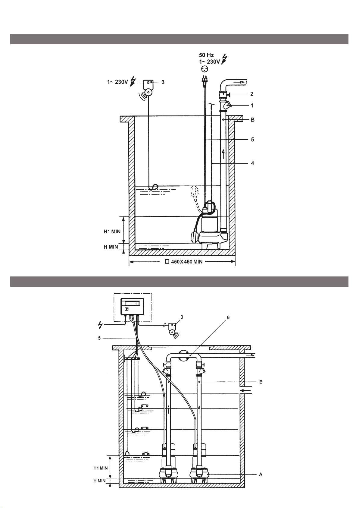
Fig. 1
Fig. 2
Page 3
English
1. General
1.1 About this document
The language of the original operating instructions is English. All other languages of these
instructions are translations of the original operating instructions.
These installation and operating instructions are
an integral part of the product. They must be kept
readily available at the place where the product is
installed. Strict adherence to these instructions
is a precondition for the proper use and correct
operation of the product.
These installation and operating instructions correspond to the relevant version of the product and
the underlying safety standards valid at the time
of going to print.
EC declaration of conformity:
A copy of the EC declaration of conformity is a
component of these operating instructions.
If a technical modification is made on the designs
named there without our agreement, this declaration loses its validity.
2. Safety
These operating instructions contain basic information which must be adhered to during installation, operation and maintenance. For this reason,
these operating instructions must, without fail, be
read by the service technician and the responsible
specialist/operator before installation and commissioning.
It is not only the general safety instructions
listed under the main point “safety” that must be
adhered to but also the special safety instructions
with danger symbols included under the following
main points.
2.1 Indication of instructions in the operating
instructions
Symbols
General danger symbol
Danger due to electrical voltage
NOTE
Signal words:
DANGER!
Acutely dangerous situation.
Non-observance results in death or the most
serious of injuries.
WARNING!
The user can suffer (serious) injuries. ‘Warning’
implies that (serious) injury to persons is probable if this information is disregarded.
CAUTION!
There is a risk of damaging the product/unit.
“Caution” implies that damage to the product
is likely if this information is disregarded.
HINWEIS:
Useful information on handling the product. It
draws attention to possible problems.
Information that appears directly on the product,
such as:
• Direction of rotation arrow,
• Identifiers for connections,
• Name plate,
• Warning sticker,
must be strictly complied with and kept in legible
condition.
2.2 Personnel qualifications
The installation, operating, and maintenance personnel must have the appropriate qualifications
for this work. Area of responsibility, terms of
reference and monitoring of the personnel are to
be ensured by the operator. If the personnel are
not in possession of the necessary knowledge,
they are to be trained and instructed. This can be
accomplished if necessary by the manufacturer of
the product at the request of the operator.
2.3 Danger in the event of non-observance of the
safety instructions
Non-observance of the safety instructions can
result in risk of injury to persons and damage
to the environment and the product/unit. Non
observance of the safety instructions results in
the loss of any claims to damages.
In detail, non-observance can, for example, result
in the following risks:
• Danger to persons from electrical, mechanical
and bacteriological influences,
• Damage to the environment due to leakage of
hazardous materials.
• Property damage
• Failure of important product/unit functions
• Failure of required maintenance and repair procedures.
2.4 Safety consciousness on the job
The safety instructions included in these installation and operating instructions, the existing
national regulations for accident prevention
together with any internal working, operating
and safety regulations of the operator are to be
complied with.
2.5 Safety instructions for inspection and installation
This appliance is not intended for use by persons
(including children) with reduced physical, sensory
or mental capabilities, or lack of experience and
knowledge, unless they have been given supervision or instruction concerning use of the appliance
by a person responsible for their safety. Children
should be supervised to ensure that they do not
play with the appliance.
• If hot or cold components on the product/the unit
lead to hazards, local measures must be taken to
guard them against touching.
• Guards protecting against touching moving compo-
8 WILO SE 06/2015
Page 4

English
nents (such as the coupling) must not be removed
whilst the product is in operation.
• Leakages (e.g. from the shaft seals) of hazardous
fluids (which are explosive, toxic or hot) must be led
away so that no danger to persons or to the environment arises. National statutory provisions are to
be complied with.
• Highly flammable materials are always to be kept at
a safe distance from the product.
• Danger from electrical current must be eliminated.
Local directives or general directives [e.g. IEC, VDE
etc.] and local power supply companies must be
adhered to.
2.6 Safety instructions for installation and maintenance work
The operator must ensure that all installation
and maintenance work is carried out by authorised and qualified personnel, who are sufficiently
informed from their own detailed study of the
operating instructions.
Work on the product/unit must only be carried out
when at a standstill. It is mandatory that the procedure described in the installation and operating
instructions for shutting down the product/unit
be complied with.
Immediately on conclusion of the work, all safety
and protective devices must be put back in position and/or recommissioned.
2.7 Unauthorised modification and manufacture of
spare parts
Unauthorised modification and manufacture of
spare parts will impair the safety of the product/
personnel and will make void the manufacturer’s
declarations regarding safety.
Modifications to the product are only permissible after consultation with the manufacturer.
Original spare parts and accessories authorised by
the manufacturer ensure safety. The use of other
parts will absolve us of liability for consequential
events.
2.8 Improper use
The operating safety of the supplied product is
only guaranteed for conventional use in accordance with Section 4 of the operating instructions.
The limit values must on no account fall under
or exceed those specified in the catalogue/data
sheet.
carbon, detergent.
– For fixed installation in a sump or a tank.
– For housing, garages, car-parks, restaurants,
boiler plants.
CAUTION! The pump must not be used for
pumping drinking water.
4.2 Description (see Fig. 1-2)
1 Check valve adapted to the conveyed medium
2 Isolating valve
3 Overflow audible signal
4 Pump lifting chain
5 Motor cable - length 5 m
6 Collector for twinned pump.
4.3 Description of pump
– Submersible monobloc electropump,
– Centrifugal single-stage with vortex impeller,
– Vertical discharge port,
– Tightness with mechanical seal and lip seal.
4.4 Description of motor
– Monophase-motor equipped with a built-in motor
cut-out, which switches the motor off if it over-
loads and automatically switches it back on again
once it has cooled down; delivered with electric
cable-length 5 m with a CEI 23-5 plug and float
switch.
Integrated capacitor.
– Protection index: IP 68
– Insulation class: B
– Oil-cooled motor.
4.5 Products delivered
– Submersible motor-driven pump complete,
– Installation and operating instructions.
4.6 Accessories
Accessories must be ordered separately.
– Isolating valve,
– Non-return valve,
– Floatswitch,
– Lifting chain,
– switch box for the automatic transmitter-
dependent control of one or two submersible
motor-driven pumps,
– Alarm switching device.
3. Transport and interim storage
The pump may only be transported/suspended
on the handle provided for transport. It is
to be protected against humidity, frost and
mechanical damage.
4. Product and accessory description
4.1 Applications
Pumps for lifting of domestic waste water:
– sewage, rainwater containing sludge and parti-
cles (except rigid particles) with traces of hydro-
9WILO SE 06/2015
Page 5
English
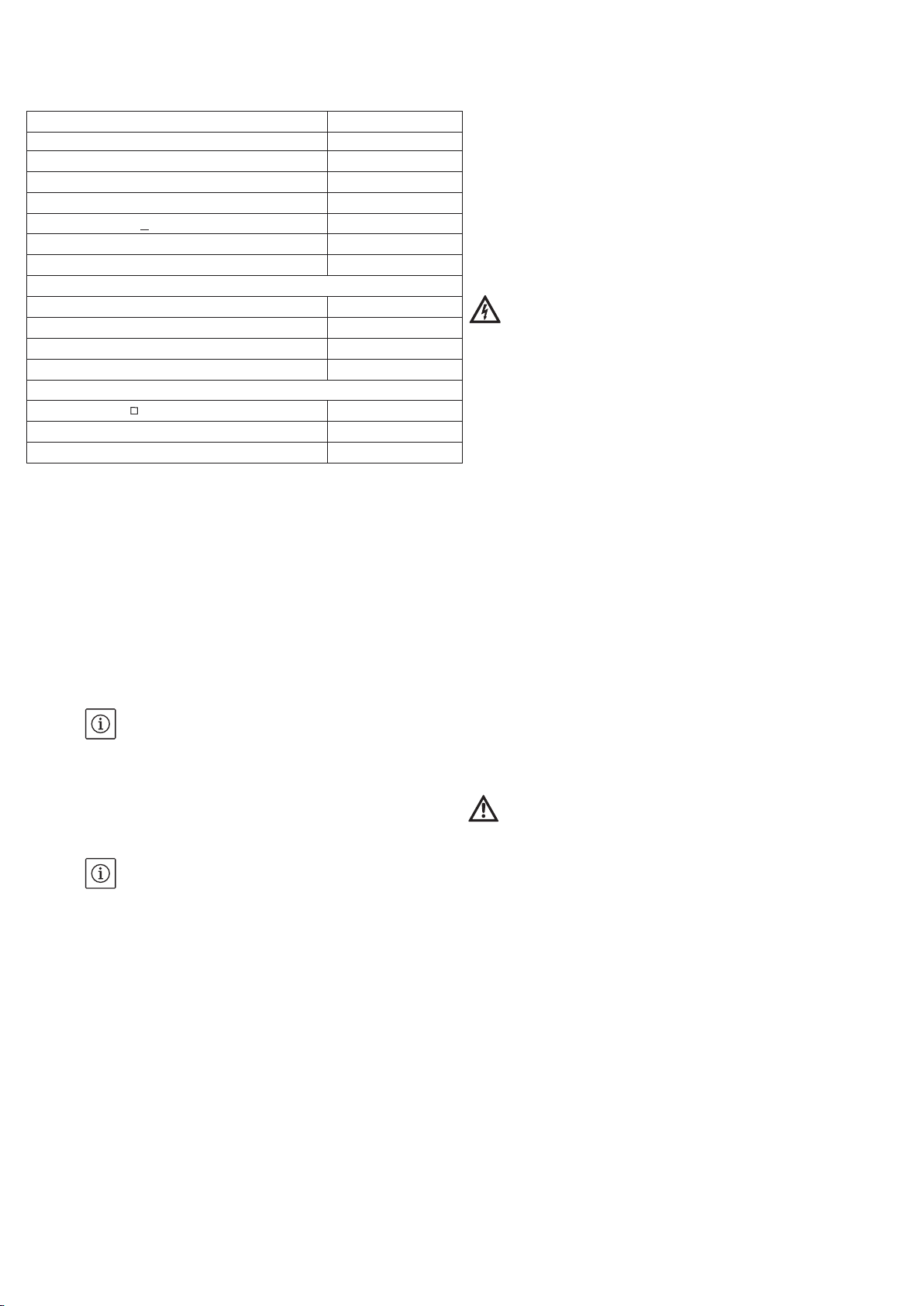
5. Product Information
Power consumption P1 [kW] see rating plate
Motor-output P2 [kW] see rating plate
Nominal current I 1~230 V [A] see rating plate
Protection class at max. immersion depth IP68
Insulation class B
Immersion depth ( ) max. [m] 2
Temperature range [°C] 3 to 40
Max. particle size [mm] Ø 40
Equipment
Cable type H07RN-F
Cable length [m] / plug 5 / Schuko (CEI 23-5)
Float switch connected
Pressure support DN 1 1/2”
Level control (Fig. 1, 2)
Shaft dimension min [mm] 450 x 450
Cut-out level continuous duty H1min [mm] 230
Cut-out level intermittent duty (short-term) Hmin [mm] 40
∆
When ordering spare parts, please give all the
information on the pump rating plate.
6. Assembly/Installation
6.1 Installation
– Fig. 1: Installation of a pump with monophase
motor, float switch and optional overflow audible
signal.
– Fig. 2: Fixed installation of 2 pumps connected
to a collector for twinned pumps and operatingcontol by 4 float switches.
NOTE:
Cut-out level:
For intermitted duty:
H min = 40 mm short-term,
For continuous duty:
H1 min = 230 mm (Fig. 1-2)
The shaft should be of ample size, so that the
motor does not start too often.
NOTE:
Lower the pump into the sump using a chain (or a
rope) hooked to the handle, never by its poweror float switch cable.
Take care not to damage the power cable of the
motor during the going down in the sump.
Avoid placing the regulators near the outlet of
the pipe through which the water enters the
sump, since this could mover them.
Keep the lowest regulator away from the pump
suction port so that it will not be sucked in.
If the installation is outside protect the discharge
pipes, the isolating and check valve, and the electric controls from frost. Connect the cables to the
overload release or to the control box.
bore isolation valve.
– Provide a 4 mm diameter hole on the discharge
pipe before the check valve for a possible vent-
ing following a draining (Fig. 1-2, pos. B).
– Installation of twinned pumps to a collector,
connect each discharge pipes to a check valve
and an isolation valve (Fig. 2).
– Seal pipe connections carefully with appropriate
products.
6.3 Electrical connection
WARNING! Electrical connection should be made
by a qualified electrician. Current national and
local regulations must be observed (e.g. VDE
regulations in Germany).
– Make sure that the electric installation is in com-
pliance with the standard IEC 364 and that the
line power supply has a high-sensitivity earth
fault breaker (max. 30 mA).
– The electrical connections have to be done
before the pump is lowered into the sump.
– Check that the type, voltage and frequency of
the electric line power supply complies with the
indications mentioned on the name plate.
– The pump with monophase motor is delivered
with a 3 wires cable equipped with a standardised plug (2 poles + earth). Connect obligatory
the cable on a socket with 2 poles + earth.
7. Commissioning
7.1 Filling and venting
– Fill up the sump,
– Check that the float switch or the level regula-
tors operate freely.
7.2 Starting
– Make sure that the sump is full of water.
CAUTION! The pump must never run dry. Dryrunning will damage the mechanical seal.
– Open the discharge valve,
– Start the pump,
– The functioning is now controlled automatically
by the float switch or the level regulators.
6.2 Hydraulic connections
– Diameter of discharge pipe (1 1/2”)
– The non-return valve must be connected to the
upper side of the discharge pipe before the full-
10 WILO SE 06/2015
Page 6

English
8. Service
DANGER! Pull the mains plug before checking
the pump!
No special servicing while the pump runs but
cleaning the impeller and draining the oil can be
necessary.
Proceed as follow:
– Separate the pump from the discharge pipe,
– Lift the pump and wash it carefully with clean
water before touching it (bear in mind the risk of
infection).
Cleaning of the impeller:
– Turn the pump upside down, remove the 3
screws of the feet, remove the feet and disman-
tle the cover.
– Avoid removing the impeller for cleaning.
Drain the motor oil:
– Place the pump horizontally,
– Remove the plug A and its seal (Fig. 3, pos. A),
– Drain the oil in a transparent receptacle,
– Check the oil: A possible presence of water
means that the mechanical seal is in bad state
and must be replaced.
Oil Quality: “MOBIL DTE Oil Medium“ or similar.
Quantity: about 0.6 litre.
9. Problems, Causes and Remedies
Problems Causes Remedies
The pump fails to start No current Check the line
Replace the fuses if necessary.
Close the overload release or the switch
of the control box
Winding or cable open-circuit Check the resistances between the cable
ends; if necessary replace the cable.
Attention: in case of replacing, reconnect
correctly the supply wires according to
the colours
Rotor blocked (the motor “growls“) Dismantle the impeller and clean it
The pump fails to deliver
or delivers too little
The pump trips out Faulty electrical installation Check the whole electrical installation
Water in oil The mechanical seals is in poor condition Let the Wilo after-sales service replace
Discharge pipe obstructed Remove the pipe and clean it
Impeller obstructed by particles see 9.1-c
The check-valve is mounted upside
down
Pump blocked see 9.1-c
The pump is hard to turn see 9.1-c
Check the direction of fitting
the mechanical seal
If the fault cannot be remedied, please
contact your plumbing and heating
specialist or your nearest Wilo customer services or representative.
Subject to technical alterations!
11WILO SE 06/2015
Page 7

Page 8

(BG) - български език (CS) - Čeština
ДЕКЛАРАЦИЯ ЗА СЪОТЕТСТВИЕ EO ES PROHLÁŠENÍ O SHODĚ
(DA) - Dansk (EL) - Ελληνικά
De er ligeledes i overensstemmelse med de harmoniserede europæiske
και επίσης με τα εξής εναρμονισμένα ευρωπαϊκά πρότυπα που αναφέρονται
(ES) - Español (ET) - Eesti keel
(FI) - Suomen kieli (HR) - Hrvatski
Lisäksi ne ovat seuraavien edellisellä sivulla mainittujen
i usklađenim europskim normama navedenim na prethodnoj stranici.
(HU) - Magyar (IT) - Italiano
EK-MEGFELELŐSÉGI NYILATKOZAT DICHIARAZIONE CE DI CONFORMITÀ
(LT) - Lietuvių kalba (LV) - Latviešu valoda
(MT) - Malti (NL) - Nederlands
DIKJARAZZJONI KE TA’ KONFORMITÀ EG-VERKLARING VAN OVEREENSTEMMING
preċedenti.
De producten voldoen eveneens aan de geharmoniseerde Europese normen
F_GQ_013-05
приелите ги национални законодателства:
předpisům, které je přejímají:
las legislaciones nacionales que les son aplicables :
seadusandlustega, mis nimetatud direktiivid üle on võtnud:
azok nemzeti jogrendbe átültetett rendelkezéseinek:
legislazioni nazionali che le traspongono :
WILO SE декларират, че продуктите посочени в настоящата декларация
съответстват на разпоредбите на следните европейски директиви и
Машини 2006/42/ЕО ; Електромагнитна съвместимост 2004/108/ЕО
както и на хармонизираните европейски стандарти, упоменати на
предишната страница.
WILO SE prohlašuje, že výrobky uvedené v tomto prohlášení odpovídají
ustanovením níže uvedených evropských směrnic a národním právním
Stroje 2006/42/ES ; Elektromagnetická Kompatibilita 2004/108/ES
a rovněž splňují požadavky harmonizovaných evropských norem uvedených
na předcházející stránce.
EF-OVERENSSTEMMELSESERKLÆRING ΔΗΛΩΣΗ ΣΥΜΜΟΡΦΩΣΗΣ EK
WILO SE erklærer, at produkterne, som beskrives i denne erklæring, er i
overensstemmelse med bestemmelserne i følgende europæiske direktiver,
samt de nationale lovgivninger, der gennemfører dem:
Maskiner 2006/42/EF ; Elektromagnetisk Kompatibilitet 2004/108/EF Μηχανήματα 2006/42/ΕΚ ; Ηλεκτρομαγνητικής συμβατότητας 2004/108/ΕΚ
standarder, der er anført på forrige side.
WILO SE δηλώνει ότι τα προϊόντα που ορίζονται στην παρούσα ευρωπαϊκά
δήλωση είναι σύμφωνα με τις διατάξεις των παρακάτω οδηγιών και τις
εθνικές νομοθεσίες στις οποίες έχει μεταφερθεί:
στην προηγούμενη σελίδα.
DECLARACIÓN CE DE CONFORMIDAD EÜ VASTAVUSDEKLARATSIOONI
WILO SE declara que los productos citados en la presenta declaración están
conformes con las disposiciones de las siguientes directivas europeas y con
Máquinas 2006/42/CE ; Compatibilidad Electromagnética 2004/108/CE Masinad 2006/42/EÜ ; Elektromagnetilist Ühilduvust 2004/108/EÜ
Y igualmente están conformes con las disposiciones de las normas europeas
armonizadas citadas en la página anterior.
WILO SE kinnitab, et selles vastavustunnistuses kirjeldatud tooted on
kooskõlas alljärgnevate Euroopa direktiivide sätetega ning riiklike
Samuti on tooted kooskõlas eelmisel leheküljel ära toodud harmoniseeritud
Euroopa standarditega.
EY-VAATIMUSTENMUKAISUUSVAKUUTUS EZ IZJAVA O SUKLADNOSTI
WILO SE vakuuttaa, että tässä vakuutuksessa kuvatut tuotteet ovat
seuraavien eurooppalaisten direktiivien määräysten sekä niihin
sovellettavien kansallisten lakiasetusten mukaisia:
Koneet 2006/42/EY ; Sähkömagneettinen Yhteensopivuus 2004/108/EY
yhdenmukaistettujen eurooppalaisten normien mukaisia.
WILO SE kijelenti, hogy a jelen megfelelőségi nyilatkozatban megjelölt
termékek megfelelnek a következő európai irányelvek előírásainak, valamint
Gépek 2006/42/EK ; Elektromágneses összeférhetőségre 2004/108/EK Macchine 2006/42/CE ; Compatibilità Elettromagnetica 2004/108/CE
valamint az előző oldalon szereplő, harmonizált európai szabványoknak. E sono pure conformi alle disposizioni delle norme europee armonizzate
WILO SE izjavljuje da su proizvodi navedeni u ovoj izjavi u skladu sa
sljedećim prihvaćenim europskim direktivama i nacionalnim zakonima:
EZ smjernica o strojevima 2006/42/EZ ; Elektromagnetna kompatibilnost smjernica 2004/108/EZ
WILO SE dichiara che i prodotti descritti nella presente dichiarazione sono
conformi alle disposizioni delle seguenti direttive europee nonché alle
citate a pagina precedente.
EB ATITIKTIES DEKLARACIJA EK ATBILSTĪBAS DEKLARĀCIJU
WILO SEdeklarē, ka izstrādājumi, kas ir nosaukti šajā deklarācijā, atbilst
WILO SE pareiškia, kad šioje deklaracijoje nurodyti gaminiai atitinka šių
Europos direktyvų ir jas perkeliančių nacionalinių įstatymų nuostatus:
Mašinos 2006/42/EB ; Elektromagnetinis Suderinamumas 2004/108/EB Mašīnas 2006/42/EK ; Elektromagnētiskās Saderības 2004/108/EK
šeit uzskaitīto Eiropas direktīvu nosacījumiem, kā arī atsevišķu valstu
likumiem, kuros tie ir ietverti:
ir taip pat harmonizuotas Europas normas, kurios buvo cituotos
ankstesniame puslapyje.
WILO SE jiddikjara li l-prodotti speċifikati f’din id-dikjarazzjoni huma
konformi mad-direttivi Ewropej li jsegwu u mal-leġislazzjonijiet nazzjonali li
japplikawhom:
Makkinarju 2006/42/KE ; Kompatibbiltà Elettromanjetika 2004/108/KE Machines 2006/42/EG ; Elektromagnetische Compatibiliteit 2004/108/EG
kif ukoll man-normi Ewropej armoniżżati li jsegwu imsemmija fil-paġna
un saskaņotajiem Eiropas standartiem, kas minēti iepriekšējā lappusē.
WILO SE verklaart dat de in deze verklaring vermelde producten voldoen
aan de bepalingen van de volgende Europese richtlijnen evenals aan de
nationale wetgevingen waarin deze bepalingen zijn overgenomen:
die op de vorige pagina worden genoemd.
Page 9

(NO) - Norsk (PL) - Polski
EU-OVERENSSTEMMELSESERKLAEING DEKLARACJA ZGODNOŚCI WE
(PT) - Português (RO) - Română
E obedecem também às normas europeias harmonizadas citadas na página
şi, de asemenea, sunt conforme cu normele europene armonizate citate în
(RU) - русский язык (SK) - Slovenčina
(SL) - Slovenščina (SV) - Svenska
pa tudi z usklajenimi evropskih standardi, navedenimi na prejšnji strani.
Det överensstämmer även med följande harmoniserade europeiska
(TR) - Türkçe
CE UYGUNLUK TEYID BELGESI
F_GQ_013-05
ulusal kanunlara uygun olduğunu beyan etmektedir:
med følgende europeiske direktiver og nasjonale lover:
transponującymi je przepisami prawa krajowego:
национальным предписаниям:
odpovedajúcich národných legislatívnych predpisov:
WILO SE erklærer at produktene nevnt i denne erklæringen er i samsvar
EG–Maskindirektiv 2006/42/EG ; EG–EMV–Elektromagnetisk kompatibilitet
2004/108/EG
og harmoniserte europeiske standarder nevnt på forrige side. oraz z nastepującymi normami europejskich zharmonizowanymi podanymi
WILO SE oświadcza, że produkty wymienione w niniejszej deklaracji są
zgodne z postanowieniami następujących dyrektyw europejskich i
Maszyn 2006/42/WE ; Kompatybilności Elektromagnetycznej 2004/108/WE
na poprzedniej stronie.
DECLARAÇÃO CE DE CONFORMIDADE DECLARAŢIE DE CONFORMITATE CE
WILO SE declara que os materiais designados na presente declaração
obedecem às disposições das directivas europeias e às legislações nacionais
que as transcrevem :
Máquinas 2006/42/CE ; Compatibilidade Electromagnética 2004/108/CE
precedente.
WILO SE declară că produsele citate în prezenta declaraţie sunt conforme cu
dispoziţiile directivelor europene următoare şi cu legislaţiile naţionale care le
transpun :
Maşini 2006/42/CE ; Compatibilitate Electromagnetică 2004/108/CE
pagina precedentă.
Декларация о соответствии Европейским нормам ES VYHLÁSENIE O ZHODE
WILO SE заявляет, что продукты, перечисленные в данной декларации
о соответствии, отвечают следующим европейским директивам и
Директива ЕС по машинному оборудованию 2006/42/ЕС ; Директива ЕС
по электромагнитной совместимости 2004/108/ЕС
и гармонизированным европейским стандартам, упомянутым на
предыдущей странице.
WILO SE čestne prehlasuje, že výrobky ktoré sú predmetom tejto
deklarácie, sú v súlade s požiadavkami nasledujúcich európskych direktív a
Strojových zariadeniach 2006/42/ES ; Elektromagnetickú Kompatibilitu
2004/108/ES
ako aj s harmonizovanými európskych normami uvedenými na
predchádzajúcej strane.
ES-IZJAVA O SKLADNOSTI EG-FÖRSÄKRAN OM ÖVERENSSTÄMMELSE
WILO SE izjavlja, da so izdelki, navedeni v tej izjavi, v skladu z določili
naslednjih evropskih direktiv in z nacionalnimi zakonodajami, ki jih
vsebujejo:
Stroji 2006/42/ES ; Elektromagnetno Združljivostjo 2004/108/ES
WILO SEbu belgede belirtilen ürünlerin aşağıdaki Avrupa yönetmeliklerine ve
Makine Yönetmeliği 2006/42/AT ; Elektromanyetik Uyumluluk Yönetmeliği
2004/108/AT
ve önceki sayfada belirtilen uyumlaştırılmış Avrupa standartlarına.
WILO SE intygar att materialet som beskrivs i följande intyg
överensstämmer med bestämmelserna i följande europeiska direktiv och
nationella lagstiftningar som inför dem:
Maskiner 2006/42/EG ; Elektromagnetisk Kompatibilitet 2004/108/EG
standarder som nämnts på den föregående sidan.
Page 10

Page 11

Page 12

Page 13

Wilo – International (Subsidiaries)
Argentina
WILO SALMSON
ArgentinaS.A.
C1295ABI Ciudad
Autónoma de Buenos Aires
T+ 54 11 4361 5929
info@salmson.com.ar
Australia
WILO Australia Pty Limited
Murrarrie, Queensland,
4172
T +61 7 3907 6900
chris.dayton@wilo.com.au
Austria
WILO Pumpen
ÖsterreichGmbH
2351 Wiener Neudorf
T +43 507 507-0
office@wilo.at
Azerbaijan
WILO Caspian LLC
1014 Baku
T +994 12 5962372
info@wilo.az
Belarus
WILO Bel OOO
220035 Minsk
T +375 17 2535363
wilo@wilo.by
Belgium
WILO SA/NV
1083Ganshoren
T +32 2 4823333
info@wilo.be
Bulgaria
WILOBulgariaLtd.
1125 Sofia
T +359 2 9701970
info@wilo.bg
Brazil
WILO Brasil Ltda
Jundiaí – São Paulo – Brasil
ZIPCode:13.213-105
T +55 11 2923 (WILO)
9456
wilo@wilo-brasil.com.br
Canada
WILOCanadaInc.
Calgary, Alberta T2A 5L4
T +1 403 2769456
bill.lowe@wilo-na.com
China
WILOChinaLtd.
101300 Beijing
T +86 10 58041888
wilobj@wilo.com.cn
Croatia
WiloHrvatskad.o.o.
10430 Samobor
T +38 51 3430914
wilo-hrvatska@wilo.hr
Czech Republic
WILOCS,s.r.o.
25101Cestlice
T +420 234 098711
info@wilo.cz
Denmark
WILO Danmark A/S
2690 Karlslunde
T +45 70 253312
wilo@wilo.dk
Estonia
WILO Eesti OÜ
12618 Tallinn
T +372 6 509780
info@wilo.ee
Finland
WILO Finland OY
02330 Espoo
T +358 207401540
wilo@wilo.fi
France
WILOS.A.S.
78390Boisd‘Arcy
T +33 1 30050930
info@wilo.fr
Great Britain
WILO(U.K.)Ltd.
Burton Upon Trent
DE14 2WJ
T +44 1283 523000
sales@wilo.co.uk
Greece
WILOHellasAG
14569 Anixi (Attika)
T +302 10 6248300
wilo.info@wilo.gr
Hungary
WILOMagyarországKft
2045Törökbálint
(Budapest)
T +36 23 889500
wilo@wilo.hu
India
WILOIndiaMatherand
PlattPumpsLtd.
Pune 411019
T +91 20 27442100
services@matherplatt.com
Indonesia
WILO Pumps Indonesia
Jakarta Selatan 12140
T +62 21 7247676
citrawilo@cbn.net.id
Ireland
WILO Ireland
Limerick
T +353 61 227566
sales@wilo.ie
Italy
WILOItalias.r.l.
20068Peschiera
Borromeo (Milano)
T +39 25538351
wilo.italia@wilo.it
Kazakhstan
WILO Central Asia
050002 Almaty
T +7 727 2785961
info@wilo.kz
Korea
WILOPumpsLtd.
618-220Gangseo,Busan
T +82 51 950 8000
wilo@wilo.co.kr
Latvia
WILOBalticSIA
1019 Riga
T +371 6714-5229
info@wilo.lv
Lebanon
WILO LEBANON SARL
Jdeideh12022030
Lebanon
T +961 1 888910
info@wilo.com.lb
Lithuania
WILOLietuvaUAB
03202 Vilnius
T +370 5 2136495
mail@wilo.lt
Morocco
WILO MAROC SARL
20600 CASABLANCA
T + 212 (0) 5 22 66 09
24/28
contact@wilo.ma
The Netherlands
WILONederlandb.v.
1551NAWestzaan
T +31 88 9456 000
info@wilo.nl
Norway
WILO Norge AS
0975 Oslo
T +47 22 804570
wilo@wilo.no
Poland
WILOPolskaSp.z.o.o.
05-506Lesznowola
T +48 22 7026161
wilo@wilo.pl
Portugal
Bombas Wilo-Salmson
PortugalLda.
4050-040 Porto
T +351 22 2080350
bombas@wilo.pt
Romania
WILORomanias.r.l.
077040Com.Chiajna
Jud.Ilfov
T +40 21 3170164
wilo@wilo.ro
Russia
WILO Rus ooo
123592Moscow
T +7 495 7810690
wilo@wilo.ru
Saudi Arabia
WILOME-Riyadh
Riyadh11465
T +966 1 4624430
wshoula@wataniaind.com
Serbia and Montenegro
WILOBeogradd.o.o.
11000 Beograd
T +381 11 2851278
office@wilo.rs
Slovakia
WILOCSs.r.o.,org.Zložka
83106Bratislava
T +421 2 33014511
info@wilo.sk
Slovenia
WILOAdriaticd.o.o.
1000 Ljubljana
T +386 1 5838130
wilo.adriatic@wilo.si
South Africa
SalmsonSouthAfrica
1610Edenvale
T +27 11 6082780
errol.cornelius@
salmson.co.za
Spain
WILOIbéricaS.A.
28806AlcaládeHenares
(Madrid)
T +34 91 8797100
wilo.iberica@wilo.es
Sweden
WILOSverigeAB
35246 Växjö
T +46 470 727600
wilo@wilo.se
Switzerland
EMBPumpenAG
4310Rheinfelden
T +41 61 83680-20
info@emb-pumpen.ch
Taiwan
WILOTaiwanCompanyLtd.
SanchongDist.,NewTaipei
City 24159
T +886 2 2999 8676
nelson.wu@wilo.com.tw
Turkey
WILO Pompa Sistemleri
San.veTic.A.S¸.
34956İstanbul
T +90 216 2509400
wilo@wilo.com.tr
Ukraina
WILOUkrainat.o.w.
01033Kiew
T +38 044 2011870
wilo@wilo.ua
United Arab Emirates
WILO Middle East FZE
JebelAliFreeZone–South
PO Box 262720 Dubai
T +971 4 880 91 77
info@wilo.ae
USA
WILO USA LLC
Rosemont, IL 60018
T +1 866 945 6872
info@wilo-usa.com
Vietnam
WILOVietnamCoLtd.
HoChiMinhCity,Vietnam
T +84 8 38109975
nkminh@wilo.vn
May 2013Furthersubsidiaries,representationandsalesofficesonwww.wilo.com
Page 14

Pioneering for You
WILO SE
Nortkirchenstraße 100
D-44263 Dortmund
Germany
T +49(0)231 4102-0
F +49(0)231 4102-7363
wilo@wilo.com
www.wilo.com
 Loading...