

Page 1
Pioneering for You
Wilo-Drain STS 65
D Einbau- und Betriebsanleitung
GB Installation and operating instructions
F Notice de montage et de mise en service
E Instrucciones de instalación y funcionamiento
I Istruzioni di montaggio, uso e manutenzione
P Manual de Instalação e funcionamento
GR Οδηγίες εγκατάστασης και λειτουργίας
TR Montaj ve kullanma kılavuzu
S Monterings- och skötselanvisning
FIN Asennus- ja käyttöohje
H Beépítési és üzemeltetési utasítás
2 081 931-Ed.02/2010-06-Kothes!
PL Instrukcja montażu i obsługi
CZ Návod k montáži a obsluze
RUS Инструкция по монтажу и эксплуатации
EST Paigaldus- ja kasutusjuhend
LV Instalēšanas un ekspluatācijas instrukcijas
LT Montavimo ir naudojimo instrukcija
SK Návod na montáž a obsluhu
SLO Navodila za vgradnjo in vzdrževanje
BG Инструкция за монтаж и експлоатация
RO Instrucţiuni de montaj şi exploatare
Page 2
6
min.
min.*
1
4
5
2
3
1
Fig.1:
1
2
3
4
5
7
6
9
9
8
10
10
Fig.2: Fig.3:
1
2
5
7
6
8
Fig.4:
6
15
15
12
4
11
min.*
min.
14
13
11
4
9
2
18
183
min.* min.*
17
17
Page 3

D Einbau- und Betriebsanleitung 3
GB Installation and operating instructions 11
F Notice de montage et de mise en service 19
E Instrucciones de instalación y funcionamiento 27
I Istruzioni di montaggio, uso e manutenzione 35
P Manual de Instalação e funcionamento 43
GR Οδηγίες εγκατάστασης και λειτουργίας 51
TR Montaj ve kullanma kılavuzu 59
S Monterings- och skötselanvisning 67
FIN Asennus- ja käyttöohje 75
H Beépítési és üzemeltetési utasítás 83
PL Instrukcja montażu i obsługi 91
CZ Návod k montáži a obsluze 99
RUS Инструкция по монтажу и эксплуатации 107
EST Paigaldus- ja kasutusjuhend 115
LV Instalēšanas un ekspluatācijas instrukcijas 123
LT Montavimo ir naudojimo instrukcija 131
SK Návod na montáž a obsluhu 141
SLO Navodila za vgradnjo in vzdrževanje 149
BG Инструкция за монтаж и експлоатация 157
RO Instrucţiuni de montaj şi exploatare 165
Page 4
English
Installation and operating instructions
1 General
About this document
These installation and operating instructions are
an integral part of the product. They must be kept
readily available at the place where the product is
installed. Strict adherence to these instructions is
a precondition for the proper use and correct
operation of the product.
These installation and operating instructions correspond to the relevant version of the product and
the underlying safety standards valid at the time
of going to print.
2Safety
These operating instructions contain basic information which must be adhered to during installation and operation. For this reason, these
operating instructions must, without fail, be read
by the service technician and the responsible
operator before installation and commissioning.
It is not only the general safety instructions listed
under the main point "safety" that must be
adhered to but also the special safety instructions
with danger symbols included under the following
main points.
2.3 Danger in the event of non-observance of the
safety instructions
Non-observance of the safety instructions can
result in risk of injury to persons and damage to
pump/installation. Non-observance of the safety
instructions can result in the loss of any claims to
damages.
In detail, non-observance can, for example, result
in the following risks :
• Failure of important pump/installation functions,
• Failure of required maintenance and repair procedures
• Danger to persons from electrical, mechanical and
bacteriological influences,
• Property damage
2.4 Safety instructions for the operator
The existing directives for accident prevention
must be adhered to.
Danger from electrical current must be eliminated.
Local directives or general directives [e.g. IEC, VDE
etc.] and local power supply companies must be
adhered to.
Risks through mechanical or bacteriological
effects must be prevented. Local conditions and
guidelines relating to sewage technology must be
adhered to.
2.1 Indication of instructions in the operating
instructions
Symbols:
General danger symbol
Danger due to electrical voltage
NOTE
Signal words:
DANGER!
Acutely dangerous situation
Non-observance results in death or the most
serious of injuries.
WARNING!
The user can suffer (serious) injuries. 'Warning'
implies that (serious) injury to persons is probable if this information is disregarded.
CAUTION!
There is a risk of damaging the pump/installation. 'Caution' implies that damage to the product is likely if the information is disregarded.
NOTE: Useful information on using the product. It
draws attention to possible problems.
2.2 Personnel qualifications
The installation personnel must have the appropriate qualifications for this work.
2.5 Safety instructions for inspection and
installation work
The operator must ensure that all inspection and
installation work is carried out by authorised and
qualified personnel, who are sufficiently informed
from their own detailed study of the operating
instructions.
Work to the pump/installation must only be carried out when at a standstill.
2.6 Unauthorised modification and manufacture of
spare parts
Modifications to the pump/installation are only
permissible after consultation with the manufacturer. Original spare parts and accessories authorised by the manufacturer ensure safety. The use of
other parts can nullify the liability from the results
of their usage.
2.7 Incorrect use
The operating safety of the supplied pump/installation is only guaranteed for conventional use in
accordance with Section 4 of the operating
instructions. The limit values must on no account
fall under or exceed those specified in the catalogue/data sheet.
Installation and operating instructions Wilo-Drain STS 65 11
Page 5
English
3 Transport and interim storage
On receipt of the product, check immediately for
transport damage. If any transport damage is
found, initiate the necessary procedure with the
forwarding agent within the period specified.
CAUTION! Danger of property damage!
Incorrect transport and incorrect storage can
lead to damage to the pump.
• When transporting, only carry or suspend the
pump by the handle/holder. The cable should
never be used for lifting!
• When transporting and storing the pump, protect it against moisture, frost and mechanical
damage.
4Intended use
The submersible pumps Wilo-Drain STS 65 are
suitable for pumping polluted water and sewage
containing air, long-fibre solids, light faeces or
sludge (up to 10 % dry mass).
They are used in:
• domestic and site drainage
• sewage and water management
• environmental and water treatment technology
• industrial and process engineering
As a rule, the pumps are used in standard sumps:
• Single pumping station: diameter up to Ø1.5 m or
1 m x 1 m
• Double pumping station: diameter up to Ø2.5 m or
2 m x 2 m
Operating mode S3-25 % means over a period of
10 minutes:
• Operation time 2.5 min.
• Standstill time 7.5 min.
In this operating mode, the pumps can be operated with/without cooling jacket with the motor
on the surface and with the following switching
levels.
• Switch-off level: top of pump housing
• Switch-on level: top of motor
If used in basins with bigger cross-sections (e.g.
rainwater storage basins), the pumps
• must be operated submerged without cooling
jacket,
• submerged or on the surface with cooling jacket.
DANGER! Mortal danger through electric shock!
The pump must not be used for draining swimming pools, garden ponds or similar installations
if there is someone in the water.
WARNING! Health hazard!
Owing to the materials used, the pumps are not
suitable for potable water! Unpurified wastewater is a health hazard.
CAUTION! Danger of property damage!
Unpermitted substances in the fluid can destroy
the pump. Abrasive solids (e.g. sand) increase
pump wear.
Pumps without an Ex certificate are not suitable
for use in potentially explosive areas.
Correct use of the pump/installation also includes
following these instructions.
Any use over and beyond these is interpreted as
incorrect use.
5 Product information
5.1 Type key
Pumps with motor seal:
• Mechanical seal against the fluid
• Rotary shaft seal against the motor compartment
Example: STS65/6-1-230-50-2
ST Sewage Technology
S Stainless Steel Motor
65 Nominal diameter of pressure port [mm]
/6 Maximum delivery head [m] when Q = 0 m³/h
1 1: Single-phase motor, 1 ~
3: Three-phase motor, 3 ~
230 Mains voltage [V]
50 Mains frequency [Hz]
2 2 pole motor
Pumps with motor seal:
• Mechanical seal against the fluid
• Mechanical seal against motor compartment
Example: STS 65F 6.60/13-3-400-50-2-CS-EX
ST Sewage Technology
S Stainless Steel Motor
65 Nominal diameter of pressure port [mm]
F Vortex impeller
6 Max. delivery head [m] when Q = 0 m³/h
60 Max. delivery head Q [m³/h]
/13 Nominal motor power P2 [kW] (value = 1/10)
3 3: Three-phase motor, 3 ~
400 Mains voltage [V]
50 Mains frequency [Hz]
2 2 pole motor
CS Cooling System - pump with cooling jacket
EX Explosion protection
12 WILO AG 05/2008
Page 6

5.2 Technical data
Mains voltages 1 ~ 230 V, ± 10 %, 3 ~ 400 V, ± 10 %
Mains frequency
50 Hz
Protection class IP 68
Nominal speed (50 Hz)
See name plate
Current consumption See name plate
Power consumption P
Nominal motor power P
Max. flow rate
Max. delivery head
Operating mode S1
1)
1
2
Without cooling jacket Motor submerged
See name plate
See name plate
See name plate
See name plate
With cooling jacket Motor on surface
Operating mode: intermittent duty S3
2)
Motor on surface:
25 % in sumps up to max. Ø3 m, or 2.5 m x 2.5 m
Recommended switching frequency 6 1/h
Max. switching frequency
20 l/h
Nominal diameter of pressure port See type key
Free ball passage
Max. submersion depth
Corresponds to nominal diameter DN [mm]
See name plate
Permitted temperature range of fluid +3 to 40 °C
Noise level at min. level
Seal:
on the fluid side Mechanical seal SiC/SiC
< 70 dB(A)
on motor side Rotary shaft seal or
mechanical seal Cr-cast/carbon
Oil filling:
Motor Volume
1.5 kW; 1~ / 3~ 2 pole 150 ml
2.5 - 4.0 kW; 2 pole 190 ml
1.5 - 4.0 kW; Ex 2 pole 230 ml
Oil type MARCOL 82 or comparable oils
Number of connections: (See section 7.2.1)
Power P
1,5 kW
2
Connections / h Zmax (acc. to DIN EN / IEC 61000-3-11)
10 0,118
20 0,086
Fuse in the power supply:
1)
Operation with a constant load until the machine can reach the thermal state of inertia.(acc. to DIN EN 60034-1)
2)
Operating time: 2.5 min., standstill time: 7.5 min. (within 10 min.)
16 A, slow
English
5.3 Scope of delivery
Pump, depending on type, with:
• 10 m replaceable electrical connecting cable
(special lengths on request)
• Single-phase type with condenser box
• Three-phase type with free cable end
• Installation and operating instructions
5.4 Accessories
Accessories have to be ordered separately:
• Switchgear for 1 or 2 pump operation
• External monitoring devices / tripping unit
• Level control (level sensor / float switch)
• Accessories for portable wet well installation
• Accessories for stationary wet well installation
• Accessories for vertical dry well installation
See the catalogue for a detailed list
Installation and operating instructions Wilo-Drain STS 65 13
Page 7

English
6 Description and function
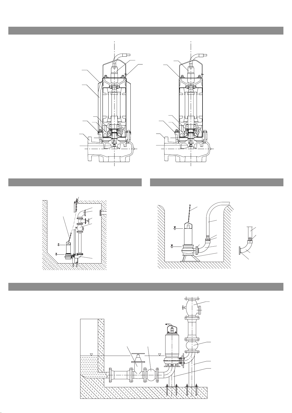
6.1 Description of the pump (Fig. 1))
Pos. Description of the
component
1 Electrical connection
cable
2
Handle/holder 7 Lantern
3 Cooling jacket 8 Mechanical seal
4
Return pipe 9 Pump housing
5
Rotary shaft seal or
mechanical seal
The submersible pumps in the Wilo-Drain STS 65
series consist of:
• Pressure encapsulated, watertight single-phase
or three-phase motor in stainless steel (1.4404 /
AISI 316L)
• Hydraulics in cast iron EN-GJL-250 (GG25)
The fluid penetrates from underneath through a
central opening and emerges from the pressure
port (DN 65) at the side. The sealing chamber
between the seal on the fluid side and the motor
side is filled with white oil when delivered. The oil
filling is used for cooling, lubricating and protecting the two seals against dry running. White oil is
biologically degradable. The oil volume depends
on the type of motor, see 5.2. of the Technical
data.
The motors are equipped with thermal motor protection (thermal winding contact) against overheating.
• Motor 1~:
on the flex L. After excessive heating, the pump is
switched off and then switched on again automatically after it has cooled down.
• Motor 3~: Three winding protection contacts
(WSK), one contact in each winding head. The
thermal winding contact must be connected to
the switchgear and evaluated there. The pump is
switched off after excessive heating. The fault
must be acknowledged via the switchgear.
One winding protection contact (WSK)
Pos. Description of the
component
6 Oil chamber
10 Impeller
7 Installation and electrical connection
DANGER! Risk of fatal injury!
Incorrect installation and improper electrical
connections can result in a risk of fatal injury.
• The installation and electrical connections
should only be done by properly skilled staff and
in compliance with the applicable regulations!
• Follow all accident prevention regulations!
7.1 Installation
The pumps of the Wilo-Drain STS 65 series are
standard for stationary/portable wet well installations. They are also suitable for stationary dry well
installation, vertically or horizontally.
CAUTION! Danger of property damage!
Danger of damage due to incorrect handling.
Using a chain or rope, only suspend the pump by
the handle or holder, never by the electric or
float switch cable or pipe/hose connection.
General
• The installation site for the pump must be free of
frost.
• The shaft must be cleared of coarse material such
as rubble before setting up and starting the pump.
• The pressure pipe must have the nominal diameter
of the pump (DN 65; it can be upgraded to DN 80).
• Install the pipes so that they are stress-free. Fix
the pipes so that the pump does not carry the
weight of the pipes.
• To protect against any backflow from the public
drainage system, install the pressure pipe as a
loop. It must be above the established backflow
level (usually street level).
• In the case of a stationary installation, install a
non-return valve and a stop valve with full passage cross-section in the pressure pipe. In double
pump systems, these fittings must be installed
over each pump.
NOTE: It is best to install the fittings outside in an
additional sump (fittings sump). If this is not feasible, the fittings should not be connected directly
to the pressure port or the pipe bend. A device to
vent the pump must be provided. Otherwise the
air cushion cannot open the non-return valve.
"Original-Wilo-accessories" are recommended to
guarantee perfect functioning of the pump.
7.1.1 Stationary wet well installation (Fig. 2)
Pos. Description of the
component
1 Foot elbow 4 Bend
2 Non-return valve 5 Installation accessories
3
Gate valve 6 Chain
• The fixed pipe connections on the pressure side
must be provided on site.
• Mount the foot elbow with the floor fixing accessories on the
• Connect the pressure pipe with the necessary fittings (accessories) on the foot elbow.
• Fix the pump bracket, profile joint on the pressure
port of the pump.
• Plug R1 ¼“ guide pipe (to be provided on site) on
to the foot elbow.
• Suspend the pump in the guide tube and lower
carefully on the chain. The pump reaches the correct operating position automatically and seals
the pressure connection on the foot elbow
through its dead weight.
• Fix the chain on the guide tube bracket with
shackle (provide on site).
Pos. Description of the
component
bottom of the sump and align it.
14 WILO AG 05/2008
Page 8

English
7.1.2 Transportable wet well installation (Fig. 3
Pos. Description of the
component
Pos. Description of the
component
4 Bend 12 Hose connection
6
Chain 13 Fixed coupling
(instead of item 12)
9 Floor supporting foot 14 Hose coupling
(instead of item 12)
11 Counter-flange 15 Pressure hose
In the case of a portable wet well installation,
secure the pump in the pit to prevent accidents
and wandering (e.g. secure the chain with slight
pre-tension).
NOTE: When used in a sump without a firm base,
the pump must be put on a sufficiently large plate
or hung from a rope or a chain in a suitable position.
7.1.3 Stationary dry well installation, for pump with
cooling jacket only (Fig 4)
Pos. Description of the
component
Pos. Description of the
component
2 Non-return valve 17 Installation set
3 Gate valve 18 Compensator
• The fixed pipe connections on the pressure side
must be provided on site.
• The weight of pipes and fittings must not be carried by the pump and compensators and must be
intercepted through the use of suitable fixings.
A resonance-free pump installation must be
•
ensured on site. The pipes
must be supported at
suitable intervals to prevent inadmissible vibrations. The use of suitable compensators is recommended for decoupling the pump.
7.2 Electrical connection
DANGER! Risk of fatal injury!
If the electrical connection is not made properly,
there is a risk of fatal injury from an electric
shock.
• Only allow the electrical connection to be made
by an electrician approved by the local electricity supplier and in accordance with the local regulations in force.
• Follow the installation and operating instructions for the pump, level control device and
other accessories.
7.2.1 Pump with single-phase motor (1~230 V)
• The motor is already wired with the condenser box
at the works. The mains connection is made at
terminals L1, N, PE of the terminal box.
• According to DIN EN / IEC 61000-3-11, the pump
is designed with a power of 1.5 kW for operating
on a power supply mains with a system impedance
Zmax on the house connection of maximum 0.118
(0.086) Ohm with a maximum number of 10 (20)
connections.
• Number of connections, see 5.2 of the Technical
data.
NOTE: If the mains impedance and the number of
connections per hour is greater than the values
specified, because of the unfavourable mains
connections, the pump may lead to temporary
voltage drops and also to disturbing voltage fluctuations, or flickering.
Therefore, measures may be necessary before the
pump can be operated correctly on this connection.
The necessary information must be obtained from
the electricity supply company and the manufacturer.
7.2.2 Pump with three-phase motor (3~400 V):
• The use of a residual current circuit-breaker is
recommended.
• The switchbox for the pump(s) is available as an
accessory.
CAUTION! Danger of property damage!
Risk of damage through incorrect electrical connection.
If the switchbox is provided by the customer on
site, the following requirements of the electricity supply companies must be met.
•P
4 kW: direct starting:
2
• Set the motor protection switch to the nominal
current of the motor according to the name
plate.
• For the thermal monitoring of the motor, a
standard evaluation device can be used to connect the thermal winding contact. Connect with
230 V AC, max. 1 A, recommended: 24V DC
Preparation of the electrical connection
• Make sure that the type of current and voltage of
the mains connection corresponds to the details
on the name plate.
• Protect the connection on the mains side: 16 A,
slow or automatic fuse with C characteristic.
• Earth the system according to regulations.
•Use a 30 mA residual current circuit-breaker.
• Use an isolating device with a min. 3 mm contact
opening to isolate from the mains.
• Connect the pump.
Installation and operating instructions Wilo-Drain STS 65 15
Page 9

English
Connecting cable
• Allocate the connecting cable wires as follows:
Pumps with P2 1.5 kW:
6-wire connection cable: 6x1.0 mm²
Wire no. 1 2 3 green/yellow 4 5
Terminal
7-wire connection cable: 6x1.5 mm²
Wire no. 1 2 3 green/
Terminal U V W PE WSK WSK not
U V W PE WSK WSK
Pumps with P2 = 1.5 kW to 4.0 kW:
4 5 6
yellow
allocated
Wire the free cable end in the switchbox (see
Switchbox installation and operating instructions).
8 Commissioning
DANGER! Danger through electric shock!
The pump must not be used for draining swimming pools, garden ponds or similar installations
if anyone is in the water.
CAUTION! Danger of property damage!
Before installation, clear the pond and the supply pipes of all solid materials such as rubble.
8.1 Checking the direction of rotation (three-phase
motors only)
WARNING! Risk of injury!
• Jerking occurs when the freely suspended pump
is switched on. People may be injured if the
pump drops down. Make sure that the pump is
safely suspended and cannot drop down.
• The rotating impeller creates an increased risk
of injury. Do not reach into the pump housing
during operation.
The pumps are checked for the correct direction
of operation and set at the works.
Check that the pump is rotating in the correct
direction before submersion.
• To do this, suspend the pump safely in a hoist.
• Switch the pump on briefly. The pump recoils in
the opposite direction (anticlockwise) to the
motor's direction of rotation.
• If the direction of rotation is incorrect, proceed as
follows:
• When using Wilo switchgear:
• The Wilo switchgear is designed so that the
connected pump is operated in the correct
direction of rotation. If the direction of rotation
is wrong, 2 phases/conductors of the mains
power supply to the switchgear must be
changed over.
• In the case of switchboxes provided on site:
• If the direction of rotation is wrong, change over
2 phases.
8.2 Setting the level control device
CAUTION! Danger of property damage!
Do not allow the mechanical seal to run dry!
Dry running shortens the service life of the
motor and the mechanical seal. If the mechanical
seal is damaged, small amounts of oil may
escape into the pumped fluid.
The water level must not drop below the permitted minimum switch-off level.
• See the installation and operating instructions for
the level control device.
The switch-off point must be chosen so that the
operating conditions indicated in Intended use are
met.
The water level ( Tmin ) (Fig. 2, 3, 4) may only
be reduced to the upper edge of the motor
( Tmin* Construction with cooling jacket). The
level control is to be set at this minimum level.
8.3 Operating conditions in a potentially explosive
environment
See additional operating instructions for
9Maintenance
Maintenance and repairs may only be carried out
by qualified experts!
It is recommended that the pump is maintained
and checked by Wilo after-sales service.
DANGER! Risk of fatal injury!
There is a mortal danger through shock when
working on electrical equipment.
• Work on electrical equipment may only be done
by electricians approved by the local electricity
supplier.
• Before working on electrical equipment, switch
it off and prevent it from being switched on
again.
• Follow the installation and operating instructions for the pump, level control device and
other accessories.
DANGER! Danger of suffocation!
Toxic or health-hazardous substances in sewage
sumps may lead to infections or suffocation.
• Only work in the pump sump when another person is present outside the sump.
• Always wear protective clothing, mouth protection and gloves when working.
9.1 Maintenance intervals
Pump stations with Wilo-Drain STS 65 pumps
must be maintained by qualified personnel
according to EN 12056-4. The intervals must not
exceed:
• ¼ year in the case of commercial companies
• ½ year in the case of apartment building stations
• 1 year in the case of detached house stations
The system operator must make sure that all the
maintenance, inspection and installation work is
done by authorised and qualified personnel, who
have acquainted themselves sufficiently with the
system through a detailed study of the installation
and operating instructions.
16 WILO AG 05/2008
Page 10

English
NOTE: When drafting a maintenance plan, expensive repairs can be avoided and a fault-free operation of the system can be achieved with a
minimum of maintenance effort. The Wilo-aftersales service is available for commissioning and
maintenance work. A maintenance report must be
issued.
9.2 Maintenance procedure
• Open pump sump, station and ventilate.
• Inspect the inside visually
• Deposits on the pump, sump floor and on the
accessories
• Shut off sewage inlet(s) (e.g. with air plugs)
• Measure the pump delivery head when Q = 0 m³/h.
• If the flow rate of the pump drops by more than
10 %, lift it out of the sump. Then check the
impeller and the pump housing for wear.
• Check the sump level.
• Drain the sump manually until slurping operation.
• Check the sump floor for deposits.
• Clean the sump if there are major deposits.
• Fill the sump and carry out a trial run.
• If the delivery head cannot be measured
• Wait until the sump is filled and the pump starts
up
• Measure the time between switching on and off
(t) and also the drop in level (h).
• Calculate the flow rate according to the following formula.
With the horizontal section A, the following general formula can be used:
Q [m³/h] = 36 x A [m
2
] x h [cm] / t [s]
Have the oil changed once a year or after 1000
operating hours during a maintenance operation.
• Provide suitable hoisting gear depending on the
weight of the pump.
• Oil type and fill volumes: see 5.2 Technical data.
NOTE: When you change the oil, the old oil and
water have to be disposed of as hazardous waste!
Sump type Formula
WB 100 Q [m³/h] = 28,3 x h [cm] / t [s]
WB 150 Q [m³/h] = 63,6 x h [cm] / t [s]
WB 200
Square sump
Q [m³/h] = 113,1 x h [cm] / t [s]
Q [m³/h] = 36 x A [m] x B [m] x h [cm] / t [s]
9.3 Oil change
WARNING! Risk of injury!
The pumps are heavy and can fall over.
People may be injured if the pump is not properly secured during maintenance work.
Always check the stability of the pump and use
suitable hoisting gear.
WARNING! Risk of injury!
An overpressure may prevail in the sealing
chamber/separation chamber.
If the oil drain plug is undone, hot oil may spurt
out under pressure and cause injury or scalding.
Before changing the oil, put on protective goggles and undo the oil drain plug with care.
WARNING! Danger to the environment!
Oil may leak out if the pump is damaged or dismantled.
This can damage the environment.
Avoid damage and adopt suitable measures to
take up the oil.
Installation and operating instructions Wilo-Drain STS 65 17
Page 11

English
10 Faults, causes and remedies
Only have faults remedied by qualified personnel! Follow the safety instructions in
9 Maintenance.
Fault Cause Remedy
Pump does not start No voltage Check the wires and fuses, or switch auto-
matic fuses in the distribution station back
on
Rotor blocked Clean the housing and impeller, if still
blocked replace the pump
Fuses, condenser defective (1~) Replace fuses, condenser
Cable rupture Check cable resistance. If necessary, change
the cable. Only use original special cable!
Safety switches thrown
Pump has no power Pump sucking air because the fluid level has
Water in the motor chamber Ask the after-sales service
Foreign bodies in the pump, winding protection contact triggered
dropped too far
Pressure pipe plugged Detach the pipe and clean it
Switch off the installation and prevent it
from being switched on again, lift the pump
out of the pit.
Remove the objects.
Check the function/setting of the level con-
trol
If the operating fault cannot be remedied,
please get in touch with the trade outlet or the
nearest customer service or agent.
11 Spare parts
Spares are ordered through local trade outlets
and/or the Wilo after-sales service.
To avoid queries and incorrect orders, always provide all of the details on the name plate with every
order.
Subject to change without prior notice!
18 WILO AG 05/2008
Page 12

D EG - Konformitatserklarung
GB EC - Declaration
of
conformity
F Declaration de conformite CE
(gemaB Anhangjaccording annexj conforme appendice lA, 2006j42jEG)
Hiermit erklaren wir, dass die Bauart der Baureihe :
Herewith,
we
declare that the product typeofthe series:
STS 65 ...
Par Ie present, nous declarons que I'agregat de la serie :
(Die Seriennummer ist auf dem Typenschild des Produktes angegeben./
The serial number is marked on the product site plate'; Le numero de serie est inscrit sur la plaque signaletique du produit.)
in der gelieferten AusfUhrung folgenden einschlagigen Bestimmungen entspricht:
in its delivered state complies with the following relevant provisions:
est conforme aux dispositions suivantes dont il releve:
EG-Maschinenrichtlinie
EC-Machinery directive
Directives CE relatives aux machines
Niederspan nungsrichtli nie
Low Voltage directive
Directive basse-tension
EG-Maschinenrichtlinie
EC-Machinery directive
Directives CE relatives aux machines
Die Schutzziele der Niederspannungsrichtlinie 2006/95/EG werden gemaB Anhang I, Nr. 1.5.1 der 2006/42/EG Maschinenrichtlinie eingehalten.
The protection objectives of the low-voltage directive 2006j95jEC are realized according annex I, No.
EC-Machinery directive 2006j42jEC.
Les objectifs protection de la directive basse-tension 2006j95jEC sont respectees conformement
directive CErelatives aux machines 2006j42jCE.
98/37/EG
(gOltig bis /valid up to /
valide jusqu'a 28.12.2009)
2006/95/EG
(gOltig bis / valid up to /
valide jusqu'a 28.12.2009)
2006/42/EG
(gOltig ab / valid from /
valide de 29.12.2009)
1.5.1
of the
a
appendice I, n°
1.5.1
de la
Elektromagnetische Vertraglichkeit - Richtlinie
Electromagnetic compatibility - directive
Compatibilite electromagnetique- directive
Bauproduktenrichtlinie
Construction product directive
Directive de produit de construction
Angewendete harmonisierte Normen, insbesondere:
Applied harmonized standards, in particular:
Normes harmonisees, notamment:
Bei einer mit uns nicht abgestimmten technischen Anderung der oben genannten Bauarten, verliert diese Erklarung ihre Gultigkeit.
If the above mentioned series are technically modified without our approval, this declaration shall no longer be applicable.
5i les gammes mentionnees ci-dessus sont modifiees sans notre approbation, cette declaration perdra sa validite.
Bevollmachtigter fUr die Zusammenstellung der technischen Unterlagen ist:
representative for the completion of the technical documentation: Mandataire pour Ie
complement de la documentation technique est:
Authorized
89/106/EWG
i.d.F/ as amended/ avec les amendements
suivants :
93j68jEWG
EN 809
EN 14121-1
EN 12100-1
EN 12100-2
EN 60335-2-41
EN 60034-1
EN 60204-1
EN 12050-1
Volker Netsch
HeimgartenstraBe 1-3
95030 Hof
Germany
IW/LOI
WILO SE
NortkirchenstraBe 100
44263 Dortmund
Germany
Page 13

NL I E
Směrnice pro stavební výrobky 89/106/EHS
znění 93/68/EHS
dyrektywą w sprawie wyrobów budowlanych 89/106/EWG
brzmieniu
Директива о строительных изделиях 89/106/EWG
поправками
EG-verklaring van overeenstemming Dichiarazione di conformità CE Declaración de conformidad CE
Hiermede verklaren wij dat di t aggregaat in de geleverde uitvoering voldoet
aan de volgende bepalingen:
EG-richtlijnen betreffende machines 98/37/EG bzw. 2006/42/EG Direttiva macchine 98/37/EG bzw. 2006/42/EG Directiva sobre máquinas 98/37/EG bzw. 2006/42/EG
De veiligheidsd oelstellingen van de laagspannings richtlijn worden
overeenkomstig bijlage I, nr. 1.5.1 van de machinerichtlijn 2006/42/EG
aangehouden.
Elektromagnetische compatibiliteit 2004/108/EG Compatibilità elettromagnetica 2004/108/EG Directiva sobre compatibilidad electromagnética 2004/108/EG
Bouwproductenrichtlijn 89/106/EEG als vervolg op 93/86/EEG Direttiva linee guida costruzione dei prodotti 89/106/CEE e seguenti
gebruikte geharmoniseerde normen, in het bijzonder: norme armonizzate applica te, in particolare: normas armoni zadas adoptadas, especialmente:
zie vorige pagina vedi pagina precedente véase página anterior
PSN
Declaração de Conformidade CE CE- försäkran EU-Overensstemmelseserklæring
Pela presente, declaramos que esta unidade no seu estado original, está
conforme os seguintes requisitos:
Directivas CEE relativas a máquinas 98/37/EG bzw. 2006/42/EG EG–Maskindirektiv 98/37/EG bzw. 2006/42/EG EG–Maskindirektiv 98/37/EG bzw. 2006/42/EG
Os objectivos de protecção da dire ctiva de baixa tensão são cumpridos de
acordo com o anexo I, nº 1.5.1 da directiva de máquinas 2006/42/CE.
Compatibilidade electromagnética 2004/108/EG EG–Elektromagnetisk kompatibilitet – riktlinje 2004/108/EG EG–EMV–Elektromagnetisk kompatibilitet 2004/108/EG
Directiva sobre produtos de construção 89/106/CEE com os aditamentos
seguintes 93/68/EWG
normas harmonizadas aplicadas, especialmente: till ämpade harmoniserade normer, i synnerhet: anvendte harmoniserte standarder, særlig:
ver página anterior se föregående sida se forrige side
FIN DK H
CE-standardinmukaisuusseloste EF-overensstemmelseserklæring EK-megfelelőségi nyilatkozat
Ilmoitamme täten, että tämä laite vastaa seuraavia asiaankuuluvia
määräyksiä:
EU–konedirektiivit: 98/37/EG bzw. 2006/42/EG EU–maskindirektiver 98/37/EG bzw. 2006/42/EG Gépek irányelv: 98/37/EK bzw. 2006/42/EK
Pienjännitedirektiivin suojatavoitteita noudatetaan
konedirektiivin 2006/42/EY liitteen I, nro 1.5.1 mukaisesti.
Sähkömagneettinen soveltuvuus 2004/108/EG Elektromagnetisk kompatibilitet: 2004/108/EG Elektromágneses összeférhetőség irányelv: 2004/108/EK
EU materiaalidirektiivi 89/106/EWG seuraavin täsmennyksin 93/68/EWG Produktkonstruktionsdirektiv 98/106/EWG følgende 93/68/EWG Építési termékek irányelv 89/106/EGK és az azt kiváltó 93/68/EGK
käytetyt yhteensovitetut standardit, e rityisesti: anvendte harmoniserede standarder, særligt: alkalmazott harmonizált s zabványoknak, különösen:
katso edellinen sivu. se forrige side lásd az előző oldalt
CZ PL RUS
Pr
ohlášení o shodě ES Deklarac ja Zgodności WE Декларация о соответствии Европейским нормам
Prohlašujeme tímto, že tento agregát vdodaném provedení odpovídá
následujícím příslušným ustanovením:
Směrnice ES pro stroj ní zařízení 98/37/ES bzw. 2006/42/ES dyrektywą maszynową WE 98/37/WE bzw. 2006/42/WE Директивы EC в отношении машин 98/37/EG bzw. 2006/42/EG
Cíle týkající se bezpečnosti stanovené ve směrnici o elektrických zařízeních
nízkého napětí jsou dodrženy podle přílohy I, č. 1.5.1 směrnice o strojních
zařízeních 2006/42/ES.
Směrnice o elektromagnetické kompatibilitě 2004/108/ES dyrektywą dot. kompatybilności elektromagnetycznej 2004/108/WE Электромагнитная устойчивость 2004/108/EG
použité harmonizační normy, zejména: stosowa nymi normami zharmonizowanymi, a w szczególności: Используемые согласованные стандарты и нормы, в частности:
viz předchozí strana patrz poprzednia strona см. предыдущую страницу
GR TR RO
Δήλωση συμμόρφωσης της ΕΕ CE Uygunluk Teyid Belgesi EC-Declaraţie de conformitate
Δηλώνουμε ότι το προϊόν αυτό σ’ αυτή την κατάσταση παράδοσης
ικανοποιεί τις ακόλουθες διατάξεις :
Οδηγίες EΚ για μηχανήματα 98/37/EK bzw. 2006/42/EΚ AB-
Οι απαιτήσεις προστασίας της οδηγίας χαμηλής τάσης τηρούνται σύμφωνα
με το παράρτημα I, αρ. 1.5.1 της οδηγίας σχετικά με τα μηχανήματα
2006/42/EG.
Ηλεκτρομαγνητική συμβατότητα EΚ-2004/108/EΚ Elektromanyetik Uyumluluk 2004/108/EG Compatibilitatea electromagnetică – directiva 2004/108/EG
Οδηγία κατασκευής 89/106/EΟΚ όπως τροποποιήθηκε 93/68/EΟΚ Ürün imalat yönetme liği 89/106/EWG ve takip eden, 93/68/EWG Directiva privind produsele pentru construcţii 89/106/EWG cu
Εναρμονισμένα χρησιμοποιούμενα πρότυπα, ιδ ιαίτερα:kısmen kullanılan standartlar için: standarde armonizate aplicate, îndeosebi:
Βλέπε προηγούμενη σελίδα bkz. bir önceki sayfa vezi pagina precedentă
EST
EÜ
vastavusdeklarats ioon EC - atbilstības deklarācija EB atitikties deklaracija
Käesolevaga tõendame, et see toode vastab järgmistele asjakohastele
direktiividele:
Masinadirektiiv 98/37/EÜ bzw. 2006/42/EÜ Mašīnu direktīva 98/37/EK bzw. 2006/42/EK Mašinų direktyvą 98/37/EB bzw. 2006/42/EB
Madalpingedirektiivi kaitse-eesmärgid on täidetud vastavalt masinate
direktiivi 2006/42/EÜ I lisa punktile 1.5.1.
Elektromagnetilise ühilduvuse direktiiv 2004/108/EÜ Elektromagnētiskās savietojamības direktīva 2004/108/EK Elektromagnetinio suderinamumo direktyvą 2004/108/EB
Ehitustoodete direktiiv 89/106/EÜ, muudetud direktiiviga 93/68/EMÜ Direktīva par būvizstrādājumiem 89/106/EK pēc labojumiem 93/68/EES Statybos produktų direktyvos 89/106/EB pataisą 93/68/EEB
kohaldatud harmoneeritud standardid, eriti: piemēroti harmoniz ēti standarti, tai skaitā: pritaikytus vieningus standartus, o būtent:
vt eelmist lk skatīt iepriekšējo lappusi žr. ankstesniame puslapyje
SK
yhlásenie o zhode ES – izjava o skladnosti EО-Декларация за съответствие
ES v
Týmto vyhlasujeme, že konštrukcie tejto konštrukčnej série v dodanom
vyhotovení vyhovujú nasle dujúcim príslušným ustanoveniam:
Stroje - smernica 98/37/ES bzw. 2006/42/ES Direktiva o strojih 98/37/ES bzw. 2006/42/ES Машинна директива 98/37/EO bzw. 2006/42/EO
Bezpečnostné ciele smernice o níz kom napätí sú dodržiavané v zmysle
prílohy I, č. 1.5.1 smernice o strojových zariadeniach 2006/42/ES.
Elektromagnetická zhoda - smernica 2004/108/ES Direktiva o elektromagnetni združljivosti 2004/108/ES Eлектромагнитна съместимост – директива 2004/108/EО
Stavebné materiály - smernica 89/106/ES pozmenená 93/68/EHP Direktiva o gradbenih proizvodih 89/106/EGS v verziji 93/68/EGS Директива за строителни мате
používané harmonizované normy, najmä: uporabljeni harmonizirani standardi, predvsem: Хармонизирани стандарти:
pozri predchádzajúcu stranu glejte prejšnjo stran вж. предната страница
M
Dikjarazzjoni ta’ konformità KE
B'dan il-mezz, niddikjaraw li l-prodotti tas-serje jissodisfaw iddispożizzjonijiet relevanti li ġejjin:
Makkinarju - Direttiva 98/37/KE bzw. 2006/42/KE
L-objettivi tas-si gurta tad-Direttiva dwar il-Vultaġġ Baxx huma konformi
mal-Anness I, Nru 1.5.1 tad-Direttiva dwar il-Makkinarju 2006/42/KE.
Kompatibbiltà elettromanjetika - Direttiva 2004/108/KE
Direttiva dwar il-prodotti tal-kostruzzjoni 89/106/KEE kif emendata bid-
Direttiva 93/68/KEE
kif ukoll standards armonizzati b'mod partikolari:
ara l-paġna ta' qabel
ve
Con la presente si dichiara che i presenti prodotti sono conformi alle
seguenti disposizioni e direttive rilevanti:
Gli obiettivi di protezi one della direttiva macchine vengono rispettati
secondo allegato I, n. 1.5.1 dalla direttiva macchine 2006/42/CE.
modifiche 93/68/CEE
Härmed förklarar vi att denna ma skin i levererat utförande motsvarar
följande tillämpliga bestämmelser:
Produkten uppfyller säkerhetsmålen i lågspänningsdirektivet enligt bilaga
I, nr 1.5.1 i maskindirektiv 2006/42/EG.
EG-Byggmaterialdirektiv 89/106/EWG med följande ändringar
93/68/EWG
Vi erklærer hermed, at denne enhed ved levering overholder følgende
relevante bestemmelser:
Lavspændingsdirektivets mål om beskyttelse overholdes i henhold til bilag
I, nr. 1.5.1 i maskindirektivet 2006/42/EF.
Niniejszym deklarujemy z pełną odpowiedzialnością, że dostarczony wyrób
jest zgodny z następującymi dokumentami:
Przes
trzegane są cele ochrony dyrektywy niskonapięciowej zgodnie z
załącznikiem I, nr 1.5.1 dyrektywy maszynowej 2006/42/WE.
93/68/EWG
Bu cihazın teslim edildiği şekliyle aşağıdaki standartlara uygun olduğunu
teyid ederiz:
Makina Standartl arı 98/37/EG bzw. 2006/42/EG Directiva CE pentru maşini 98/37/EG bzw. 2006/42/EG
Alçak gerilim yönergesinin koruma hedefleri, 2006/42/AT makine
yönergesi Ek I, no. 1.5.1'e uygundur.
LV LT
Ar šo mēs apliecinām, ka šis izstrādājums atbilst sekojošiem noteikumiem: Šiuo pažymima, kad šis gaminys atitinka šias normas ir direktyvas:
Zemsprieguma direktīvas drošības mērķi tiek ievēroti atbilstoš i Mašīnu
direktīvas 2006/42/EK pielikumam I, Nr. 1.5.1.
SLO BG
Izjavljamo, da dobavljene vrste izvedbe te serije ustrezajo sledečim
zadevnim določilom:
Cilji Direkt ive o nizkonapetostni opremi so v skl adu s
prilogo I, št. 1.5.1 Direktive o strojih 2006/42/EG doseženi.
w
Por la presente declaramos la conformidad del producto en su estado de
suministro con las disposiciones pertinentes siguientes:
Se cumplen los objetivos en materia de seguridad establecidos en la
Directiva de Baja tensión según lo especificado en el
Anexo I, punto 1.5.1 de la Directiva de Máquinas 2006/42/CE.
Directiva sobre productos de construcción 89/106/CEE modificada por
93/68/CEE
Vi erklærer hermed at denne e nheten i utførelse som levert er i
overensstemmelse med følgende relevante bestemmelser:
Lavspenningsdirektivets vernemål overholdes i samsvar med
vedlegg I, nr. 1.5.1 i maskindirektivet 2006/42/EF.
Byggevaredirektiv 89/106/EWG med senere tilføyelser 93/68/EWG
Ezennel kijelentjü k, hogy az berendezés megfelel az al ábbi irányelveknek:
A kisfeszültségű irányelv védelmi előírásait a
2006/42/EK gépekre vonatkozó irányelv I. függelékének 1.5.1. sz. pontja
szerint teljesíti.
irányelv
Настоящим документом заявляем, что данный агрегат в его объеме
поставки соответствует следующим нормативным док ументам:
Требования по безопасности, изложенные в директиве по
низковольтному напряжению, соблюдаются согласно приложению I,
№ 1.5.1 директивы в отношении машин 2006/42/ЕG.
93/68/EWG
Prin prezenta declarăm că acest produs aşa cum este livrat, corespunde cu
următoarele prevederi aplicabile:
Sunt respectate obiectivele de protecţie din directiva privind joasa tensiune
conform Anexei I, Nr. 1.5.1 din directiva privind maşinile 2006/42/CE.
amendamentele ulterioare 93/68/EWG
Laikomasi Žemos įtampos direktyvos keliamų saugos reikalavimų pagal
Mašinų direktyvos 2006/42/EB I priedo 1.5.1 punktą.
Декларираме, че продуктът отговаря на следните изисквания:
Целите за защита на разпоредбата за ниско напрежение са съставени
съгласно. Приложение I, № 1.5.1 от Директивата за машини
2006/42/EС.
93/68/ЕИО
WILO SE
WILO SE
Nortkirchenstraße 100
Nortkirchenstraße 100
44263 Dortmund
Germany
риали 89/106/ЕИО изменени
с
Page 14

WILO AG
Nortkirchenstraße 100
44263 Dortmund
Germany
T +49 231 4102-0
F +49 231 4102-7363
wilo@wilo.de
www.wilo.com
Algeria
Bad Ezzouar, Dar El Beida
T +213 21 247979
chabane.hamdad@salmson.fr
Armenia
375001 Yerevan
T +374 10 544336
info@wilo.am
Bosnia and Herzegovina
71000 Sarajevo
T +387 33 714510
zeljko.cvjetkovic@wilo.ba
Georgia
0177 Tbilisi
T +995 32317813
info@wilo.ge
Macedonia
1000 Skopje
T +389 2 3122058
valerij.vojneski@wilo.com.mk
Moldova
2012 Chisinau
T +373 2 223501
sergiu.zagurean@wilo.md
Rep. Mongolia
Ulaanbaatar
T +976 11 314843
wilo@magicnet.mn
Tajikistan
734025 Dushanbe
T +992 37 2232908
farhod.rahimov@wilo.tj
Turkmenistan
744000 Ashgabad
T +993 12 345838
wilo@wilo-tm.info
Uzbekistan
700046 Taschkent
sergej.arakelov@wilo.uz
May 2008
Wilo – International (Subsidiaries)
Wilo – International (Representation offices)
Argentina
WILO SALMSON
Argentina S.A.
C1270ABE Ciudad
Autónoma de Buenos Aires
T +54 11 43015955
info@salmon.com.ar
Austria
WILO Handelsges. m.b.H.
1230 Wien
T +43 507 507-0
office@wilo.at
Azerbaijan
WILO Caspian LLC
1065 Baku
T +994 12 5962372
info@wilo.az
Belarus
WILO Bel OOO
220035 Minsk
T +375 17 2503393
wilobel@wilo.by
Belgium
WILO SA/NV
1083 Ganshoren
T +32 2 4823333
info@wilo.be
Bulgaria
WILO Bulgaria Ltd.
1125 Sofia
T +359 2 9701970
info@wilo.bg
Canada
WILO Canada Inc.
Calgary, Alberta T2A 5L4
T +1 403 2769456
bill.lowe@wilo-na.com
China
WILO China Ltd.
101300 Beijing
T +86 10 80493900
wilobj@wilo.com.cn
Croatia
WILO Hrvatska d.o.o.
10090 Zagreb
T +38 51 3430914
wilo-hrvatska@wilo.hr
Czech Republic
WILO Praha s.r.o.
25101 Cestlice
T +420 234 098711
info@wilo.cz
Denmark
WILO Danmark A/S
2690 Karlslunde
T +45 70 253312
wilo@wilo.dk
Estonia
WILO Eesti OÜ
12618 Tallinn
T +372 6509780
info@wilo.ee
Finland
WILO Finland OY
02330 Espoo
T +358 207401540
wilo@wilo.fi
France
WILO S.A.S.
78390 Bois d'Arcy
T +33 1 30050930
info@wilo.fr
Great Britain
WILO (U.K.) Ltd.
DE14 2WJ BurtonUpon-Trent
T +44 1283 523000
sales@wilo.co.uk
Greece
WILO Hellas AG
14569 Anixi (Attika)
T +302 10 6248300
wilo.info@wilo.gr
Hungary
WILO Magyarország Kft
2045 Törökbálint
(Budapest)
T +36 23 889500
wilo@wilo.hu
Ireland
WILO Engineering Ltd.
Limerick
T +353 61 227566
sales@wilo.ie
Italy
WILO Italia s.r.l.
20068 Peschiera
Borromeo (Milano)
T +39 25538351
wilo.italia@wilo.it
Kazakhstan
WILO Central Asia
050002 Almaty
T +7 727 2785961
in.pak@wilo.kz
Korea
WILO Pumps Ltd.
621-807 Gimhae
Gyeongnam
T +82 55 3405800
wilo@wilo.co.kr
Latvia
WILO Baltic SIA
1019 Riga
T +371 7 145229
mail@wilo.lv
Lebanon
WILO SALMSON
Lebanon
12022030 El Metn
T +961 4 722280
wsl@cyberia.net.lb
Lithuania
WILO Lietuva UAB
03202 Vilnius
T +370 5 2136495
mail@wilo.lt
The Netherlands
WILO Nederland b.v.
1948 RC Beverwijk
T +31 251 220844
info@wilo.nl
Norway
WILO Norge AS
0901 Oslo
T +47 22 804570
wilo@wilo.no
Poland
WILO Polska Sp. z.o.o.
05-090 Raszyn
T +48 22 7026161
wilo@wilo.pl
Portugal
Bombas Wilo-Salmson
Portugal Lda.
4050-040 Porto
T +351 22 2080350
bombas@wilo.pt
Romania
WILO Romania s.r.l.
077040 Com. Chiajna
Jud. Ilfov
T +40 21 3170164
wilo@wilo.ro
Russia
WILO Rus ooo
123592 Moscow
T +7 495 7810690
wilo@orc.ru
Saudi Arabia
WILO ME - Riyadh
Riyadh 11465
T +966 1 4624430
wshoula@wataniaind.com
Serbia and Montenegro
WILO Beograd d.o.o.
11000 Beograd
T +381 11 2851278
office@wilo.co.yu
Slovakia
WILO Slovakia s.r.o.
82008 Bratislava 28
T +421 2 45520122
wilo@wilo.sk
Slovenia
WILO Adriatic d.o.o.
1000 Ljubljana
T +386 1 5838130
wilo.adriatic@wilo.si
South Africa
Salmson South Africa
1610 Edenvale
T +27 11 6082780
errol.cornelius@
salmson.co.za
Spain
WILO Ibérica S.A.
28806 Alcalá de Henares
(Madrid)
T +34 91 8797100
wilo.iberica@wilo.es
Sweden
WILO Sverige AB
35246 Växjö
T +46 470 727600
wilo@wilo.se
Switzerland
EMB Pumpen AG
4310 Rheinfelden
T +41 61 83680-20
info@emb-pumpen.ch
Taiwan
WILO-EMU Taiwan Co. Ltd.
110 Taipeh
T +886 227 391655
nelson.wu@
wiloemutaiwan.com.tw
Turkey
WILO Pompa Sistemleri
San. ve Tic. A.S¸.
34530 Istanbul
T +90 216 6610211
wilo@wilo.com.tr
Ukraina
WILO
Ukraina
t.o.w.
01033 Kiew
T +38 044 2011870
wilo@wilo.ua
Vietnam
Pompes Salmson Vietnam
Ho Chi Minh-Ville Vietnam
T +84 8 8109975
nkm@salmson.com.vn
United Arab Emirates
WILO ME - Dubai
Dubai
T +971 4 3453633
info@wilo.com.sa
USA
WILO-EMU USA LLC
Thomasville,
Georgia 31792
T +1 229 5840097
info@wilo-emu.com
USA
WILO USA LLC
Melrose Park, Illinois 60160
T +1 708 3389456
mike.easterley@
wilo-na.com
Page 15

WILO AG
Nortkirchenstraße 100
44263 Dortmund
Germany
T 0231 4102-0
F 0231 4102-7363
wilo@wilo.de
www.wilo.de
G1 Nord
WILO AG
Vertriebsbüro Hamburg
Beim Strohhause 27
20097 Hamburg
T 040 5559490
F 040 55594949
hamburg.anfragen@wilo.de
G2 Ost
WILO AG
Vertriebsbüro Berlin
Juliusstraße 52–53
12051 Berlin-Neukölln
T 030 6289370
F 030 62893770
berlin.anfragen@wilo.de
G3 Sachsen/Thüringen
WILO AG
Vertriebsbüro Dresden
Frankenring 8
01723 Kesselsdorf
T 035204 7050
F 035204 70570
dresden.anfragen@wilo.de
G4 Südost
WILO AG
Vertriebsbüro München
Landshuter Straße 20
85716 Unterschleißheim
T
089
4200090
F 089 42000944
muenchen.anfragen@wilo.de
G5 Südwest
WILO AG
Vertriebsbüro Stuttgart
Hertichstraße 10
71229 Leonberg
T 07152 94710
F 07152 947141
stuttgart.anfragen@wilo.de
G6 Rhein-Main
WILO AG
Vertriebsbüro Frankfurt
An den drei Hasen 31
61440 Oberursel/Ts.
T 06171 70460
F 06171 704665
frankfurt.anfragen@wilo.de
G7 West
WILO AG
Vertriebsbüro Düsseldorf
Westring 19
40721 Hilden
T
02103
90920
F 02103 909215
duesseldorf.anfragen@wilo.de
Kompetenz-Team
Gebäudetechnik
WILO AG
Nortkirchenstraße 100
44263 Dortmund
T 0231 4102-7516
T 01805 R•U•F•W•I•L•O*
7•8•3•9•4•5•6
F 0231 4102-7666
Kompetenz-Team
Kommune
Bau + Bergbau
WILO EMU GmbH
Heimgartenstraße 1
95030 Hof
T 09281 974-550
F 09281 974-551
Werkskundendienst
Gebäudetechnik
Kommune
Bau + Bergbau
Industrie
WILO AG
Nortkirchenstraße 100
44263 Dortmund
T 0231 4102-7900
T 01805 W•I•L•O•K•D*
9•4•5•6•5•3
F
0231
4102-7126
Erreichbar Mo–Fr von
7–17 Uhr.
Wochenende und feiertags
9–14 Uhr elektronische
Bereitschaft mit
Rückruf-Garantie!
–Kundendienst-Anforderung
–Werksreparaturen
–Ersatzteilfragen
–Inbetriebnahme
–Inspektion
–Technische Service-Beratung
–Qualitätsanalyse
Wilo-International
Österreich
Zentrale Wien:
WILO Handelsgesellschaft mbH
Eitnergasse 13
1230 Wien
T +43 507 507-0
F +43 507 507-15
Vertriebsbüro Salzburg:
Gnigler Straße 56
5020 Salzburg
T +43 507 507-13
F +43 507 507-15
Vertriebsbüro Oberösterreich:
Trattnachtalstraße 7
4710 Grieskirchen
T +43 507 507-26
F +43 507 507-15
Schweiz
EMB Pumpen AG
Gerstenweg 7
4310 Rheinfelden
T +41 61 83680-20
F +41 61 83680-21
Standorte weiterer
Tochtergesellschaften
Argentinien, Aserbaidschan,
Belarus, Belgien, Bulgarien,
China, Dänemark, Estland,
Finnland, Frankreich,
Griechenland, Großbritannien,
Irland, Italien, Kanada,
Kasachstan, Korea, Kroatien,
Lettland, Libanon, Litauen,
Niederlande, Norwegen,
Polen, Portugal, Rumänien,
Russland, Saudi-Arabien,
Schweden, Serbien und
Montenegro, Slowakei,
Slowenien, Spanien,
Südafrika, Taiwan,
Tschechien, Türkei, Ukraine,
Ungarn, Vereinigte Arabische
Emirate, Vietnam, USA
Die Adressen finden Sie unter
www.wilo.de oder
www.wilo.com.
Stand Mai 2008
Erreichbar Mo–Fr von 7–18 Uhr.
–
Antworten
auf
– Produkt- und Anwendungsfragen
– Liefertermine und Lieferzeiten
–Informationen
über Ansprechpartner vor Ort
–Versand von Informationsunterlagen
* 14 Cent pro Minute aus dem deutschen Festnetz
der T-Com. Bei Anrufen aus Mobilfunknetzen
sind Preisabweichungen möglich.
Wilo-Vertriebsbüros in Deutschland
 Loading...