

Wilo Drain LPC 80, Drain LPC 40, Drain LPC 50 Installation And Operating Instructions Manual
Page 1
Wilo-Drain LPC
D Einbau- und Betriebsanleitung
GB Installation and operating instructions
F Notice de montage et de mise en service
2 081 598-Ed.01/2007-08-Kothes!
Page 2
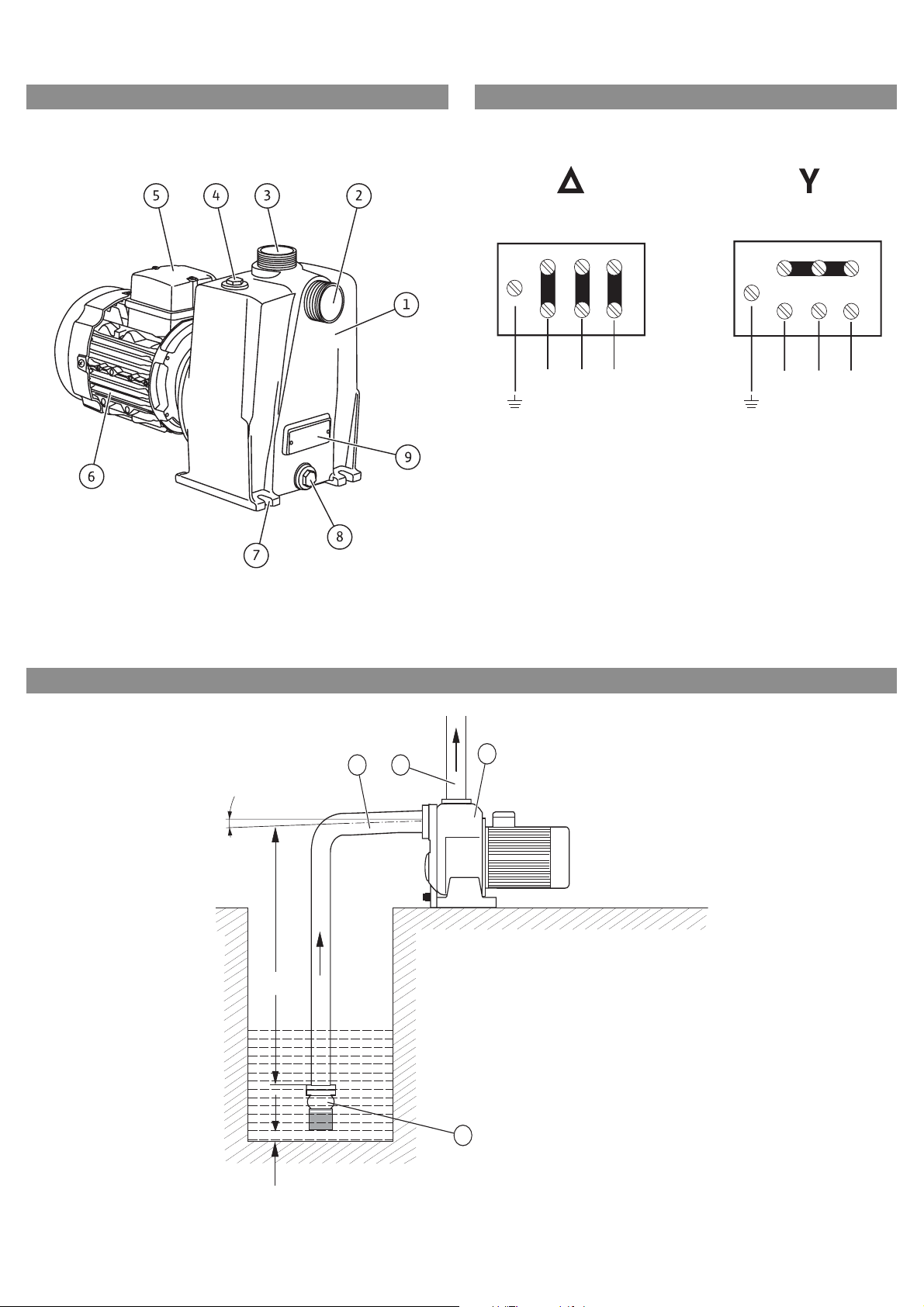
Fig.1: Fig.2:
Fig.3:
ZXY
UVW
ZXY
UVW
min. 2%
max. 7,5 m
min. 0,1 m
3
2
1
4
Page 3

D Einbau- und Betriebsanl ei t u ng 3
GB Installation and operating instructions 8
F Notice de montage et de mise en service 13
Page 4

Page 5

Deutsch
Einbau- und Betriebsanleitung
1 Allgemeines
Über dieses Dokument
Die Einbau- und Betriebsanleitung ist Bestandteil
des Produktes. Sie ist jederzeit in Produktnähe
bereitzustellen. Das genaue Beachten dieser
Anweisung ist Voraussetzung für den bestimmungsgemäßen Gebrauch und die richtige Bedienung des Produktes.
Die Einbau- und Betriebsanleitung entspricht der
Ausführung des Produktes und dem Stand der
zugrunde gelegten sicherheitstechnischen Normen bei Drucklegung.
2Sicherheit
Diese Betriebsanleitung enthält grundlegende
Hinweise, die bei Aufstellung und Betrieb zu
beachten sind. Daher ist diese Betriebsanleitung
unbedingt vor Montage und Inbetriebnahme vom
Monteur sowie dem zuständigen Betreiber zu
lesen.
Es sind nicht nur die unter diesem Hauptpunkt
Sicherheit aufgeführten allgemeinen Sicherheitshinweise zu beachten, sondern auch die unte r den
folgenden Hauptpunkten mit Gefahrensymbolen
eingefügten, speziellen Sicherheitshinweise.
2.1 Kennzeichnung von Hinweisen in der
Betriebsanleitung
Symbole:
Allgemeines Gefahrensymbol
Gefahr durch elektrische Spannung
NÜTZLICHER HINWEIS
Signalwörter:
GEFAHR!
Akut gefährliche Situation.
Nichtbeachtung führt zu Tod oder schwersten
Verletzungen.
WARNUNG!
Der Benutzer kann (schwere) Verletzungen
erleiden. 'Warnung' beinhaltet, dass (schwere)
Personenschäden wahrscheinlich sind, wenn der
Hinweis missachtet wird.
VORSICHT!
Es besteht die Gefahr, die Pumpe/Anlage zu
beschädigen. 'Vorsicht' bezieht sich auf mögliche Produktschäden durch Missachten des Hinweises.
HINWEIS: Ein nützlicher Hinweis zur Handhabung
des Produktes. Er macht auch auf mögliche
Schwierigkeiten aufmerksam.
2.3 Gefahren bei Nichtbeachtung der
Sicherheitshinweise
Die Nichtbeachtung der Sicherheitshinweise kann
eine Gefährdung für Personen und Pumpe/Anlage
zur Folge haben. Die Nichtbeachtung der Sicherheitshinweise kann zum Verlust jeglicher Schadenersatzansprüche führen.
Im einzelnen kann Nichtbeachtung beispielsweise
folgende Gefährdungen nach sich ziehen:
• Versagen wichtiger Funktionen der Pumpe/
Anlage,
• Versagen vorgeschriebener Wartungs- und Reparaturverfahren
• Gefährdungen von Personen durch elektrische,
mechanische und bakteriologische Einwirkungen,
• Sachschäden
2.4 Sicherheitshinweise für den Betreiber
Die bestehenden Vorschriften zur Unfallverhütung sind zu beachten.
Gefährdungen durch elektrische Energie sind aus zuschließen. Weisungen lokaler oder genereller
Vorschriften [z.B. IEC, VDE usw.] und der örtlichen
Energieversorgungsunternehmen sind zu beachten.
2.5 Sicherheitshinweise für Inspektions- und
Montagearbeiten
Der Betreiber hat dafür zu sorgen, dass alle
Inspektions- und Montagearbeiten von autorisiertem und qualifiziertem Fachpersonal ausgeführt werden, das sich durch eingehendes
Studium der Betriebsanleitung ausreichend infor miert hat.
Die Arbeiten an der Pumpe/Anlage dürfen nur im
Stillstand durchgeführt werden.
2.6 Eigenmächtiger Umbau und
Ersatzteilherstellung
Veränderungen der Pumpe/Anlage sind nur nach
Absprache mit dem Hersteller zulässig. Originalersatzteile und vom Hersteller autorisiertes Zubehör
dienen der Sicherheit. Die Verwendung anderer
Teile kann die Haftung für die daraus entstehenden Folgen aufheben.
2.7 Unzulässige Betriebsweisen
Die Betriebssicherheit der gelieferten Pumpe/
Anlage ist nur bei bestimmungsgemäßer Verwendung entsprechend Abschnitt 4 der Betriebsanleitung gewährleistet. Die im Katalog/Datenblatt
angegebenen Grenzwerte dürfen auf keinen Fall
unter- bzw. überschritten werden.
3 Transport und Zwischenlagerung
2.2 Personalqualifikation
Das Personal für die Montage muss die entsprechende Qualifikation für diese Arbeiten aufweisen.
Einbau- und Betriebsanleitung Wilo-Drain LPC 3
Sofort nach Erhalt des Produkts:
• Produkt auf Transportschäden überprüfen,
• Transportschäden in den Lieferpapieren dokumentieren, vom Spediteur gegenzeichnen lassen
und umgehend den Hersteller informieren.
Page 6
Deutsch
VORSICHT! Gefahr von Sachschäden!
Unsachgemäßer Transport und unsachgemäße
Zwischenlagerung können zu Sachschäden am
Produkt führen.
• Pumpe stets vorsichtig transportieren.
• Pumpe vor der Lagerung entleeren.
• Pumpe an einem trockenen und frostfreien Ort
lagern.
• Beim Benzin-Verbrennungsmotors die
Betriebsanleitung des Motors beachten.
Pumpe zur Zwischenlagerung entleeren
• Pumpe ausschalten und gegen Wiedereinschalten
sichern.
• Revisionsöffnung/Entleerungsöffnung öffnen
und Wasser vollständig ablaufen lassen.
• Revisionsöffnung/Entleerungsöffnung wieder
verschließen.
4 Bestimmungsgemäße Verwendung
Die Pumpen der Baureihe Wilo-Drain LPC dienen
zur Förderung von Schmutzwasser mit geringem
Feststoffanteil. Einsatzgebiete:
• Entwässerung von Baugruben
• Entleerung von Teichen
• Abpumpen von Sickerwasser
• Beregnung / Berieselung von Gärten und Grünanlagen
WARNUNG! Erstickungsgefahr!
Die Abgase von Verbrennungsmotoren sind giftig und beim Einatmen von Abgasen besteht
Erstickungsgefahr. Pumpen mit Verbrennungsmotoren nur im Freien verwenden, niemals in
geschlossenen Räumen!
WARNUNG! Gesundheitsgefahr!
Durch die eingesetzten Werkstoffe ist die
Pumpe nicht zur Förderung von Trinkwasser
geeignet! Durch Verunreinigung mit Abwasser
besteht die Gefahr von Gesundheitsschäden.
Pumpen nicht für Trinkwasser einsetzen!
VORSICHT! Gefahr von Sachschäden!
Die Förderung unzulässiger Stoffe kann zu
Sachschäden am Produkt führen. Niemals salzoder chlorhaltiges Wasser und niemals Stoffe
wie z. B. grobes Papier, Schutt, Müll, Schlachtabfälle, langfaserige Stoffe, oder Schwimmbadwasser fördern!
Zur bestimmungsgemäßen Verwendung gehört
auch die Einhaltung dieser Anleitung.
Jede darüber hinausgehende Verwendung gilt als
nicht bestimmungsgemäß.
5 Angaben über das Erzeugnis
5.1 Typenschlüssel
Beispiel: LPC 40/19 3-400-50-2 M
LP Selbstansaugende Pumpe (Lifting Pump)
CGrauguss (cast iron)
40 Nennweite (DN 40)
/19 Maximale Förderhöhe [m]
3-400 Elektromotor: 3~400 V
-50 Frequenz 50 Hz
-2 2 polig
M Mobil: Ausführung mit Handwagen
Beispiel: LPC 40/27 PM
LP Selbstansaugende Pumpe (Lifting Pump)
CGrauguss (cast iron)
40 Nennweite (DN 40)
/27 Maximale Förderhöhe [m]
P Petrol: 4-Takt Benzin-Verbrennungsmotor
M Mobil: Ausführung mit Handwagen
5.2 Technische Daten LPC 40 LPC 50 LPC 80
Pumpe
Saugstutzen / Druckstutzen G 1 1/2" (DN40) G 2" (DN50) G 3" (DN80)
Max. Korngröße
Gehäusewerkstoff
Laufradwerkstoff
Werkstoff Gleitringdichtung
Werkstoff statische Dichtung
< 4 mm < 4 mm < 4 mm
Aluminiumguss Grauguss EN-GJL-250 Grauguss EN-GJL-250
EN-GJL-250 EN-GJL-250 EN-GJL-250
Kohle / Aluminiumoxid Kohle / Aluminiumoxid SiC / SiC
NBR NBR NBR
Elektromotor LPC 40 LPC 50
Motornennleistung P
2
Nennstrom
Frequenz
Wicklung Drehstrom 230 - 400 V
Drehzahl
siehe Typenschild
siehe Typenschild
50 Hz
2900 min
-1
Isolierstoffklasse F
Schutzart IP55
Betriebsart
Kühlung
S1
Luftkühlung
4 WILO AG 08/2007
Page 7
4-Takt Benzin-Verbrennungsmotor LPC 40 LPC 50
Motorleistung 2,21kW / 3 PS 3,68 kW / 5PS
Hubraum
127 cm
3
205 cm
3
Kraftstoffart Siehe Betriebsanleitung des Benzin-Verbrennungsmotors
Tankvolumen
2,8 l
Leerlaufdrehzahl 3600 1/min
Kühlung Luftkühlung
Anlasser manuell, Seilstarter
Deutsch
5.3 Lieferumfang
5.3.1 Stationäre Ausführung
• Pumpe mit Elektronormmotor ohne Kabel oder
mit Benzin-Verbrennungsmotor
• Einbau- und Betriebsanleitung Pumpe
• Bei Benzin-Verbrennungsmotor, Betriebsanleitung zum Motor
5.3.2 Transportable Ausführung
• Pumpe mit Elektronormmotor ohne Kabel oder
mit Benzin-Verbrennungsmotor mit Handwagen
•Einbau- und Betriebsanleitung Pumpe
• Bei Benzin-Verbrennungsmotor, Betriebsanleitung zum Motor
5.4 Empfohlenes Zubehör
Zubehör muß gesondert bestellt werden:
• Schlauchkupplung
• Saugschlauch mit Saugsieb
• Motorschutzschalter
•Absperrventile
• Rückschlagklappe
6 Beschreibung und Funktion
Die Pumpen der Baureihe Wilo-Drain LPC sind
selbstansaugende Kreiselpumpen mit offenem
Mehrkanallaufrad. Die Antriebswelle und
Saugstutzen sind horizontal ausgeführt, der
Druckstutzen ist vertikal angeordnet.
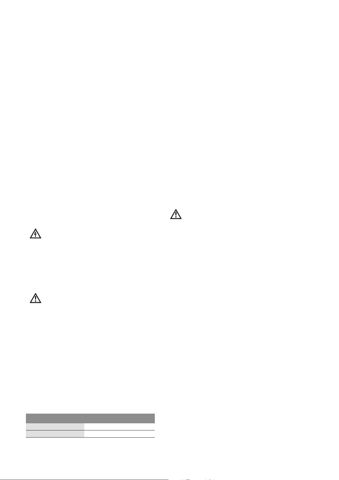
Beschreibung der Pumpe (Fig. 1) :
1 Pumpengehäuse
2 Saugstutzen
3 Druckstutzen
4 Einfüll-/Entlüftungsöffnung
5 Anschlusskasten für Kabel (nur bei
Elektromotor, nicht LPC...P)
6 Motor
7 Befestigungslaschen
8 Revisionsöffnung (LPC 40 mit
Entleerungsstopfen)
9 Typenschild
Weitere Merkmale:
• eingebaute Rückschlagklappe (nur LPC 40)
• Gleitringdichtung und statische Dichtung zur
Abdichtung der Wellendurchführung
• Revisionsöffnung zur Reinigung der Pumpe
(nicht LPC 40)
7 Installation und elektrischer Anschluss
GEFAHR! Lebensgefahr!
Unsachgemäße Installation und unsachgemäßer
elektrischer Anschluss können lebensgefährlich
sein.
• Installation und elektrischen Anschluss nur
durch Fachpersonal und gemäß geltender Vorschriften durchführen lassen!
• Vorschriften zur Unfallverhütung beachten!
HINWEIS Für einen optimalen Betrieb der Pumpe
Originalzubehör von Wilo verwenden, siehe Katalog.
7.1 Installation
VORSICHT! Gefahr von Sachschäden!
Bei Frost kann das Fördemedium einfrieren und
die Pumpe zerstören.
• Sicherstellen, dass der Aufstellungsort frostfrei
ist.
Zu große Feststoffteile können die Pumpe zerstören.
• Mit passendem Ansaugfilter in der Saugleitung
sicherstellen, dass die max. zulässige Korngröße
nicht überschritten wird.
Unsachgemäße Aufstellung kann die Pumpe
beschädigen.
• Bei mobilen Pumpen auf sichere Aufstellung
achten.
• Bei Festinstallation Grundplatte mit Fundament
verschrauben.
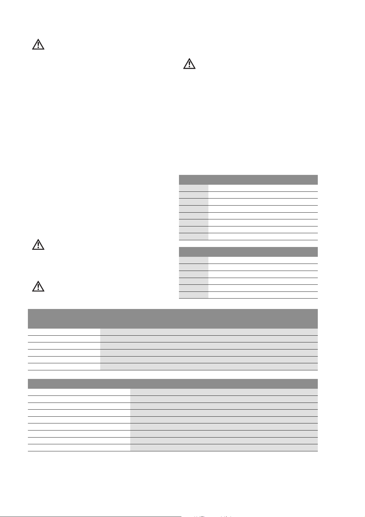
Installationsbeispiel (Fig. 3)
Fig.3 stellt ein Beispiel für eine Festinstallation
mit Zubehör dar:
1 Pumpe
2 Saugleitung (Zubehör)
3 Druckleitung (Zubehör)
4 Saugsieb (Zubehör)
7.1.1 Vor der Installation beachten
• Saugleitung mit mindestens 2% Gefälle (Fig.3)
ansteigend zur Pumpe hin verlegen, damit sich
keine Luftblasen in der Ansaugleitung festsetzen.
• Saugleitung als starre Leitung ausführen.
• Saugleitung so kurz wie möglich ausführen.
Druckverluste z. B. durch Kniestücke, Verengungen oder Ventile nach Möglichkeit vermeiden.
• Durchmesser der Saugleitung muss mindestens
der Nennweite der Pumpe entsprechen, um
Ansaugvermögen und Pumpenleistung nicht zu
beeinträchtigen.
• Durchmesser der Druckleitung muss mindestens
der Nennweite der Pumpe entsprechen.
Einbau- und Betriebsanleitung Wilo-Drain LPC 5
Page 8
Deutsch
• Bei mobilen Pumpen kann die Druckleitung entweder starr oder flexibel ausgeführt werden.
• Dichtungsmaterial bereithalten (z. B. mit Teflonband).
• Rohrleitungen nicht oberhalb des Motors verlegen, um herabtropfendes Schwitzwasser zu vermeiden.
• Bei mobilen Anlagen ist kein Fußventil erforderlich, da die Pumpen bereits mit einer Rückschlagklappe im Ansaugstutzen ausgestattet sind.
7.1.2 Pumpe installieren
• Mobile Pumpe:
Pumpe mit Handwagen zum Einsatzort bringen,
auf einer ebenen Fläche abstellen und gegen
Wegrollen sichern.
• Pumpe für Festinstallation:
Pumpe am Einsatzort aufstellen und mit Ankerschrauben über die Befestigungslaschen auf Fundament verschrauben.
• Saug- und Druckleitung anschließen und sorgfältig abdichten.
• Notwendiges Zubehör installieren, siehe Katalog.
• Pumpe mit 4-Takt Benzin-Verbrennungsmotor:
Keine weiteren Installationsarbeiten erforderlich.
• Pumpe mit Elektromotor:
Elektromotor anschließen, siehe Abschnitt Elektrischer Anschluss.
7.2 Elektrischer Anschluss (nur bei Elektromotor)
GEFAHR! Lebensgefahr!
Bei unsachgemäßem elektrischem Anschluss
besteht Lebensgefahr durch Strom schlag.
• Elektrischen Anschluss nur durch einen vom
örtlichen Energieversorger zugelassenen Elektroinstallateur und gemäß geltender Vorschriften ausführen lassen.
• Vor dem Anschließen Spannungsversorgung
unterbrechen und gegen Wiedereinschalten
sichern.
VORSICHT! Gefahr von Sachschäden!
Trockenlauf kann die Gleitringdichtung zerstören.
• Pumpe vor Prüfung der Motordrehrichtung
sachgemäß befüllen und entlüften.
• Pumpe niemals trocken laufen lassen.
7.2.1 Vor dem Anschließen beachten
• Alle geltenden Vorschriften beachten und einhalten.
• Spannungsversorgung unterbrechen und gegen
Wiedereinschalten sichern.
• Sicherstellen, dass die elektrische Versorgung den
Angaben auf dem Typenschild entspricht. Die verfügbare elektrische Leistung muss für den Anlaufstrom (6- bis 8-facher Nennstrom) ausreichen
• Geeignete 4-adrige elektrische Anschlussleitung
bereithalten, Leitungsquerschnitt beachten:
• Fehlerstromschutzschalter (max. 30 mA) für den
Personenschutz einsetzen.
• Sicherungsautomat für den auf dem Typenschild
angegebenen Nennstrom zum Schutz des Elektromotors einsetzen.
• Allpoligen Trennschalter mit Mindestkontaktöffnungsweite von 3 mm und Schmelzsicherung vorsehen.
• Sicherstellen, dass die elektrischen Anschlüsse vor
Feuchtigkeit geschützt sind.
7.2.2 Motor anschließen (Fig. 2)
• Klemmenanschlusskasten öffnen.
• Motor entsprechend Fig.2 an die Anschlussleitung anschließen. Kabelenden fest verschrauben.
• Motor vorschriftsmäßig erden.
• Sicherstellen, dass die Kabeldurchführung spritzwasserdicht ist.
• Klemmenanschlusskasten fest verschließen.
• Der Motor muss gegen Überlast durch einen
Motorschutzschalter abgesichert werden. Für den
Direktanlauf den Motorschutzschalter auf den
Motornennstrom des Motortypenschildes einstellen.
8 Inbetriebnahme
VORSICHT! Gefahr von Sachschäden!
Trockenlauf kann die Gleitringdichtung zerstören.
• Pumpe und System vor der Inbetriebnahme
sachgemäß befüllen und entlüften.
• Pumpe niemals trocken laufen lassen.
Pumpe füllen/entlüften
• Schraubstopfen aus der Einfüll-/Entlüftungsöffnung (Fig. 1/Pos.4) herausschrauben.
• Pumpe bis zur Einfüll-/Entlüftungsöffnung mit
Wasser füllen.
• Schraubstopfen in die Einfüll-/Entlüftungsöffnung einschrauben.
Motordrehrichtung prüfen
• Motor kurz einschalten und prüfen, ob der Motorlüfter sich in der auf dem Pumpengehäuse mit
einem Pfeil markierten Drehrichtung dreht.
• Bei falscher Motordrehrichtung:
• Spannungsversorgung unterbrechen und gegen
Wiedereinschalten sichern.
• Anschlüsse von zwei Phasen tauschen (Fig.2).
Pumpe einschalten
• Alle Ventile im System öffnen.
• Pumpe einschalten. Der Ansaugvorgang kann
zwischen einigen Sekunden und 5Minuten dauern. (Fig. 2)
Anschlussspannung LPC 40 LPC 50
3~230 V 4 x 1,5mm
3~400 V 4 x 1,5mm
6 WILO AG 08/2007
2
2
4x1,5mm
4x1,5mm
2
2
Page 9
Deutsch
9Wartung
GEFAHR! Lebensgefahr!
Bei Arbeiten an elektrischen Bauteilen besteht
Lebensgefahr durch Stromschlag.
• Arbeiten an elektrischen Bauteilen nur durch
eine Elektrofachkra ft und gemäß geltender Vorschriften ausführen lassen.
• Vor Arbeiten an elektrischen Bauteilen Spannungsversorgung unterbrechen und gegen Wiedereinschalten sichern.
WARNUNG! Verletzungsgefahr!
An rotierenden Bauteilen besteht Verletzungsgefahr bei Berührung.
• Vor allen Wartungsarbeiten Pumpe ausschalten
und gegen Wiedereinschalten sichern.
VORSICHT! Gefahr von Sachschäden!
Unsachgemäße oder unzureichende Wartung
kann zu Schäden am Verbrennungsmotor führen. Betriebsanleitung des Benzin-Verbrennungsmotors beachten.
WARNUNG! Gefahr von Gesundheitsschäden!
Betriebstoffe können gesundheits- und
umweltschädigend sein.
• Mit Betriebsstoffen stets vorsichtig umgehen
und Hautkontakt vermeiden, nicht schlucken!
• Betriebsstoffe stets umweltgerecht entsorgen.
Überholung von Pumpen, die Flüssigkeiten mit
Feststoffanteilen befördert haben.
Durchsatz und Druck lassen nach, wenn die Pumpenkammer zu stark verschlissen ist. In diesem Fall
sollte das Laufrad, das Leitrad, die Verschleißplatte und in den meisten Fällen auch die Gleitringdichtung erneuert werden. Es wird empfohlen
diese Arbeiten durch den Wilo Kundendienst
durchführen zu lassen.
Angaben zu Wartungsarbeiten der Benzin-Verbrennungsmotoren sind in der Betriebsanleitung
zum Motor enthalten.
10 Störungen, Ursachen und Beseitigung
GEFAHR! Lebensgefahr!
Bei unsachgemäßer Störungsbeseitigung
besteht Lebensgefahr durch Stromschlag.
• Störungsbeseitigung nur durch qualifiziertes
Fachpersonal durchführen lassen!
• Vor allen Arbeiten Pumpe ausschalten, Spannungsversorgung unterbrechen und gegen Wiedereinschalten sichern.
Störungen Ursachen Beseitigung
Pumpe saugt nicht an. Falsche Vorgehensweise bei der Inbetrieb-
nahme.
Pumpe saugt Luft an. Dichtheit der Rohrleitungen prüfen.
Saugsieb verstopft. Saugsieb reinigen.
Druckstutzen verstopft. Rohrleitung abbauen und Druckstutzen rei-
Saugseitig integrierte Rückschlagklappe
blockiert (nur LPC 40).
Zu große Ansaughöhe. Ansaughöhe prüfen (max. 7,5m) und
Kein oder geringer Durchsatz. Saugsieb verstopft. Sieb reinigen.
Drehrichtung des Motors falsch. Anschlüsse von zwei Phasen durch Elektro-
Leitrad verstopft. Kundendienst anfordern.
Laufrad ist verschlissen.
Motorschutzschalter löst aus oder
Motor wird heiß.
Lässt sich die Betriebsstörung nicht beheben,
wenden Sie sich bitte an das Fachhandwerk oder
an die nächstgelegene Wilo Kundendienststelle
oder Vertretung.
Zu geringe verfügbare Leistung. Verfügbare Leistung netzseitig prüfen las-
Laufrad blockiert. Kundendienst anfordern.
Eine Phase ist unterbrochen. Ursache durch Elektrofachkraft finden und
Bedienungsanleitung beachten.
nigen.
Saugstutzen demontieren und Rückschlagklappe deblockieren/reinigen.
Anlage ggf. anpassen.
fachkraft vertauschen lassen.
sen. Bei unzureichender Leistung Energieversorger kontaktieren.
beseitigen lassen.
11 Ersatzteile
Die Ersatzteil-Bestellung erfolgt über örtliche
Fachhandwerker und/oder den Wilo Kunden-
dienst.
Um Rückfragen und Fehlbestellungen zu vermeiden, sind bei jeder Bestellung sämtliche Daten des
Typenschildes anzugeben.
Technische Änderungen vorbehalten !
Einbau- und Betriebsanleitung Wilo-Drain LPC 7
Page 10

English
Installation and operating instructions
1 General information
About this document
These installation and operating instructions are
an integral part of the product. They must be kept
readily available at the place where the product is
installed. Strict adherence to th ese inst r uct io ns is
a precondition for the proper use and correct
operation of the product.
These installation and operating instructions correspond to the relevant version of the product and
the underlying safety standards valid at the time
of going to print.
2Safety
These operating instructions contain basic information which must be adhered to during installations and operation. For this reason, these
operating instructions must, without fail, be read
by the service technician and the responsible
operator before installation and commissioning.
It is not only the general safety ins truct ion s list ed
under the main point “safety” that must be
adhered to but also the special safety instructions
with danger symbols included under the following
main points.
2.1 Designation of information in the operating
instructions
Symbols:
General danger symbols
2.3 Danger in event of non-observance of the
safety instructions
Non-observance of the safety instructions can
result in risk of injury to persons and damage to
pump/unit. Non-observance of the safety
instructions can result in the loss of any claims to
damages.
In detail, non-observance can, for example, result
in the following risks:
• Failure of important pump/unit functions,
• Failure of required maintenance and repair procedures,
• Danger to persons from electrical, mechanical and
bacteriological influences,
• Property damage
2.4 Safety instructions for the operator
The existing directives for accident prevention
must be adhered to.
Danger from electrical current must be eliminated.
Local directives or general directives [e.g. IEC, VDE
etc.] and local power supply companies must be
adhered to.
2.5 Safety instructions for inspection and
installation work
The operator must ensure that all inspection and
installation work is carried out by authorised and
qualified personnel, who are sufficiently informed
from their own detailed study of the operating
instructions.
Work to the pump/unit must only be carried out
when at a standstill.
Danger due to electrical voltage
NOTE: …
Signal words:
DANGER!
Acutely dangerous situation.
Non-observance results in death or the most
serious of injuries.
WARNING!
The user can suffer (serious) injuries. ‘Warning’
implies that (serious) injury to persons is probable if this information is disregarded.
CAUTION!
There is a risk of damaging the pump/unit. ‘Caution’ implies that damage to the product is likely
if the information is disregarded.
NOTE: Useful information on using the product. It
draws attention to possible problems.
2.2 Personnel qualification
The installation personnel must have the appropriate qualification for this work.
2.6 Unauthorised alteration and spare part
production
Alterations to the pump/unit are only permissible
after consultation with the manufacturer. Original
spare parts and accessories authorised by the
manufacturer ensure safety. The use of other
parts can nullify the liability from the results of
their usage.
2.7 Unacceptable operating modes
The operating safety of the supplied pump/unit is
only guaranteed for conventional use in accordance with Section 4 of the operating instructions.
The limit values must on no account fall under or
exceed those specified in the catalogue/data
sheet.
3 Transport and temporary storage
As soon as the product is received:
• check the product for any transport damage,
• document the transport damage in the shipping
documents, have it signed by the forwarding
agent and inform the manufacturer immediately.
8 WILO AG 08/2007
Page 11

English
CAUTION! Danger of material damage!
Improper transport or temporary storage can
result in damage to the product.
• Always transport the pump with care.
• Drain the pump prior to storage.
• Store the pump somewhere dry and frost-free.
• Observe the operating instructions of the combustion engine.
Draining the pump for temporary storage
• Switch off the pump and secure it against being
switched back on again.
• Open the access/drain opening and drain the
water entirely.
• Close the access/drain opening again.
4Intended use
The pumps of the Wilo-Drain LPC series are for
pumping wastewater with a low proportion of
solid particles. Areas of application:
• Draining excavation ditches
• Draining ponds
• Pumping out seepage water
• Spraying/irrigation of gardens and lawns
WARNING! Danger of suffocation!
The exhaust fumes of combustion engines are
toxic. There is a danger of suffocation if they are
inhaled. Only use pumps with combustion
engines outdoors, never indoors!
WARNING! Health hazard!
Due to the materials used, the pump is not suitable for pumping drinking water! Contamination
with wastewater poses a health hazard. Do not
use pumps for drinking water!
CAUTION! Danger of material damage!
Pumping impermissible substances can damage
the product. Never pump water containing salt
or chlorine and never pump substances such as
rough paper, rubble, waste, animal waste, longfibred material or swimming pool water!
Proper use includes following these instructions.
Any other use is considered improper.
5 Product details
5.1 Type key
Example: LPC 40/19 3-400-50-2 M
LP Self-priming pump (lifting pump)
C Grey cast ir on
40 Nominal width (DN 40)
/19 Maximum delivery head [m]
3-400 Electric motor: 3~400 V
-50 Frequency 50 Hz
-2 2-pole
M Mobile: version with trolley
Example: LPC 40/27 PM
LP Self-priming pump (lifting pump)
C Grey cast ir on
40 Nominal width (DN 40)
/27 Maximum delivery head [m]
P Petrol: four-stroke combustion engine (petrol)
M Mobile: version with trolley
5.2 Technical Data LPC 40 LPC 50 LPC 80
Pump
Suction port / discharge port G 1 1/2" (DN40) G 2" (DN50) G 3" (DN80)
Max. Korngröße
Housing material
Impeller material
Material of mechanical seal Carbon / aluminiumoxide Carbon / aluminium oxide SiC / SiC
Material of static seal
Electric motor
Rated motor power P
Rated current
Frequency 50 Hz
Winding
Speed
Insulating material class F
Protection class
Operating mode
Cooling Air cooling
2
< 4 mm < 4 mm < 4 mm
Cast aluminium Grey cast iron EN-GJL-250 Grey cast iron EN-GJL-250
EN-GJL-250 EN-GJL-250 EN-GJL-250
NBR NBR NBR
See data plate
See data plate
Three-phase current 230 - 400 V
2900 rpm
IP55
S1
Installation and operating instructions Wilo-Drain LPC 9
Page 12

English
Four-stroke combustion engine LPC 40 LPC 50
Engine power 2,21 kW / 3PS 3,68kW / 5 PS
Cubic capacity
127 cm
3
205 cm
3
Fuel type See the operating instructions for the combustion engine
Tank capacity
2,8 l
No-load speed 3600 1/rpm
Cooling Air cooling
Starter Manual, pull starter
5.3 Scope of delivery
5.3.1 Stationary version
• Pump with standard electric motor without cable
or with combustion engine
• Pump installation and operating instructions
• For combustion engine, operating inst ructions f or
the engine
5.3.2 Transportable version
• Pump with standard electric motor without cable
or with combustion engine with trolley
• Pump installation and operating instructions
• For combustion engine, operating inst ructions f or
the engine
5.4 Recommended accessories
Accessories must be ordered separately:
•Hose coupling
• Suction hose with filter
• Motor protection switch
•Stop valves
• Non-return valve
6 Description and function
7 Installation and electrical connection
DANGER! Danger to life!
Improper installation and incorrect electrical
connections can result in fatal injury.
• The installation and electrical connections
should only be made by properly skilled staff
and in compliance with applicable regulations!
• Follow all accident prevention regulations!
NOTE Use original accessories from Wilo, see catalogue, for the optimum operation of the pump.
7.1 Installation
CAUTION! Danger of material damage!
Frost can freeze the pumping fluid and destroy
the pump.
• Make sure that the installation site is frost-free.
Solid particles that are too large can destroy the
pump.
• Use the appropriate inlet filter in the suction line
to make sure that the maximum permissible
grain size is not exceeded.
If set up incorrectly, this can damage the pump.
• Make sure that mobile pumps are set up
securely.
• For a fixed installation, screw the base plate to
the foundation.
The pumps of the Wilo-Drain LPC series are selfpriming centrifugal pumps with open multivane impeller. Drive shaft and suction port are
horizontal, the discharge port is arranged vertically.
Description of the pump (fig. 1):
1 Pump housing
2 Suction port
3 Discharge port
4 Feed/breather hole
5 Connection box for cables (only for electric
motor, not LPC...P)
6 Motor
7 Mounting links
8 Access opening (LPC 40 with drain plug)
9 Data plate
Other features:
• Built-in non-return valve (only LPC 40)
• Mechanical seal and static seal for sealing the
shaft passage
• Access opening for cleaning the pump
(not LPC 40)
Installation example (fig. 3)
Fig. 3 shows an example of a fixed installation with
accessories:
1Pump
2 Suction line (accessory)
3 Pressure line (accessory)
4 Intake strainer (accessory)
7.1.1 Observe the following prior to installation
• Lay the suction line with a gradient of at least 2%
(fig. 3) in upward direction towards the pump so
that no air bubbles can get trapped in the intake
line.
• The suction line should be a rigid line.
• The suction line should be as short as possible.
Avoid pressure losses if possible, e.g. due to elbow
pipes, constrictions or valves.
• The diameter of the suction line should at least be
equivalent to the pump's nominal width so as not
to affect the suction capacity and pump performance.
• The diameter of the pressure line must at least be
equivalent to the pump's nominal width.
• With mobile pumps, the pressure line may be
either rigid or flexible.
• Hold sealing material ready (e.g. with teflon tape).
10 WILO AG 08/2007
Page 13
English
• Do not lay pipes above the motor to avoid condensation water dripping.
• No foot valve is required for mobile systems, since
the pumps are already equipped with a non-return
valve in the intake port.
7.1.2 Installing the pump
• Mobile pump:
Use a trolley to move the pump to the installation
location, set it down on a flat surface and secure it
against rolling away.
• Pump for fixed installation:
Set up the pump at the installation location and
use anchor screws to screw it on to the foundation
at the mounting links.
• Connect suction and pressure lines and seal them
carefully.
• See the catalogue for the installation of the
accessories required.
• Pump with four-stroke combustion engine:
No more installation work required.
• Pump with electric motor:
Connect the electric motor, see section Electrical
Connection.
7.2 Electrical connection (only for electric motors)
DANGER! Danger to life!
If the electrical connection is not established
properly, there is a risk of fatal injury from an
electric shock.
• The electrical connection should only be made
by an electrician approved by the local energy
provider and in accordance with the applicable
regulations.
• Prior to establishing the connection, disconnect
the power supply and secure it against being
switched back on again.
CAUTION! Danger of material damage!
Dry running can destroy the mechanical seal.
• Before checking the motor's direction of rotation, fill and bleed the pump correctly.
• Never let the pump run dry.
7.2.1 Observe the following prior to connecting
• Observe and comply with all applicable regulations.
• Disconnect the power supply and secure it against
being switched back on again.
• Make sure that the power supply complies with
the data on the data plate. The available electrical
power must be sufficient for the starting current
(6 to 8 times the rated current).
• Keep a suitable 4-core electrical connection line
ready and observe the line diameter:
• Use residual current circuit breakers (max. 30 mA)
to protect the operator.
• Use an automatic circuit breaker for the rated current specified on the data plate to protect the
electric motor.
• Provide an all-pole disconnector with a minimum
contact opening width of 3 mm and fusible link.
• Make sure that the electrical connections are protected from moisture.
7.2.2 Connecting the motor (fig. 2)
• Open the terminal box.
• Connect the motor to the connection line as
shown in fig. 2. Connect the cable ends firmly.
• Earth the motor as required by the regulations.
• Make sure that the cable passage is splash-proof.
• Close the terminal box firmly.
• The motor must be protected against overloading
by a motor protection switch. For a direct start, set
the motor protection switch to the rated motor
current on the motor's data plate.
8 Commissioning
CAUTION! Danger of material damage!
Dry running can destroy the mechanical seal.
• Before commissioning, fill and bleed the pump
correctly.
• Never let the pump run dry.
Filling/bleeding the pump
• Remove the screw plug from the feed/breather
hole (fig. 1, pos. 4).
• Fill the pump with water up to the feed/breather
hole.
• Insert the plug screw in the feed/breather hole.
Checking the motor's direction of rotation
• Switch on the motor briefly and check whether
the motor fan rotates in the direction marked by
an arrow on the pump housing.
• If the motor's direction of rotation is incorrect:
• Disconnect the power supply and secure it
against being switched back on again.
• Exchange the connections of two phas es
(fig. 2).
Switching on the pump
• Open all valves in the system.
• Switch on the pump. The suction process can take
between a few seconds and 5minutes.
Anschlussspannung LPC 40 LPC 50
3~230 V 4 x 1,5mm
3~400 V 4 x 1,5mm
Installation and operating instructions Wilo-Drain LPC 11
2
2
4x1,5mm
4x1,5mm
2
2
Page 14

English
9Maintenance
DANGER! Danger to life!
When working on electrical components, there
is a risk of fatal injury from an electric shock.
• Work on electrical components should only be
carried out by an electrician in accordance with
the applicable regulations.
• Prior to work on electrical components, disconnect the power supply and secure it against
being switched back on again.
WARNING! Risk of injury!
There is a risk of being injured if rotating components are touched.
• Prior to all maintenance work, switch off the
pump and secure it against being switched back
on again.
CAUTION! Danger of material damage!
Incorrect or insufficient maintenance can damage the combustion engine. Observe the operating instructions for the combustion engine.
WARNING! Health hazard!
Operating supplies can damage your health or
pollute the environment.
• Always handle operating supplies with care and
prevent skin contact. Do not swallow!
• Always dispose of operating supplies in an environmentally sound manner.
Maintenance of pumps used to pump liquids
containing solid particles.
Delivery rate and pressure are reduced if the
pumping chamber is too severely worn. In this
case, the impeller, the diffuser, the wear plate and
in most cases also the mechanical seal have to be
replaced. It is recommended to have this work
performed by Wilo customer service.
Information on the maintenance work for the
combustion engines can be found in the operating
instructions for the engine.
10 Problems, causes and remedies
DANGER! Danger to life!
Incorrect troubleshooting poses a risk of fatal
injury from an electric shock.
• Troubleshooting should only be carried out by
qualified specialists!
• Prior to all work, switch off the pump, disconnect the power supply and secure it against
being switched back on again.
Fault Causes Remedy
Pump does not suck. Incorrect procedure during commissioning. Observe the operating instructions.
Pump sucks in air. Check the pipes for leaks.
Intake strainer clogged. Clean intake strainer.
Discharge port clogged. Remove pipe and clean discharge port.
Integrated non-return val ve on suctio n side
blocked (only LPC 40).
Suction height too high. Check suction height (max. 7.5m) and
No or insufficient delivery. Intake strainer clogged. Clean strainer.
Motor's direction of rota tion incorrect. Have the connections of two phases
Diffuser blocked. Request customer service.
Impeller is worn.
Motor protection switch triggers
or motor gets hot.
If the fault cannot be fixed, please contact your
regional specialist or your nearest Wilo customer service location or representative.
Available power insufficient. Check available power on mains side. If
Impeller blocked. Request customer service.
One phase is interrupted. Have an electrician find the cause and elim-
Dismantle suction port and remove blockage from/clean non-return valve.
adapt system if necessary.
exchanged by an electrician.
power insufficient, contact the energy provider.
inate it.
11 Spare parts
Spare parts can be ordered from your local specialist and/or via Wilo customer service.
To avoid queries and incorrect orders, always
specify all details on the data plate with every
order.
We reserve the right to make technical changes !
12 WILO AG 08/2007
Page 15

Français
Notice de montage et de mise en service
1 Généralités
À propos de ce document
La notice de montage et de mise en service fait
partie intégrante du matériel et doit toujours être
disponible en permanence à proximité du produit.
Le strict respect de ces instructions est une condition nécessaire à l’installation et à l’utilisation
conformes du matériel.
La rédaction de la notice de montage et de mise en
service correspond à la version du matériel et aux
normes de sécurité en vigueur à la date de son
impression.
2Sécurité
Ce manuel renferme des instructions essentielles
qui doivent être respectées lors du montage et de
l’utilisation. Ainsi il est indispensable que l’installateur et l’opérateur du matériel en prennent connaissance avant de procéder au montage et à la
mise en service.
Les instructions à respecter ne sont pas uniquement celles de sécurité générale de ce chapitre,
mais aussi celles de sécurité particulière qui figurent dans les chapitres suivants, accompagnées
d’un symbole de danger.
2.1 Signalisation des consignes de la notice
Symboles :
Symbole général de danger
Consignes relatives aux risques électriques
REMARQUE UTILE
SIGNAUX :
DANGER!
Situation extrêmement dangereuse.
Le non-respect entraîne la mort ou des blessures graves.
AVERTISSEMENT !
L’utilisateur peut souffrir de blessures (graves).
« Avertissement » implique que des dommages
corporels (graves) sont vraisemblables lorsque
l’indication n’est pas respectée.
ATTENTION !
Il existe un risque d’endommager la pompe/installation. « Attention » signale une instruction
dont la non-observation peut engendrer en
dommage pour le matériel et son fonctionnement.
REMARQUE: Remarque utile sur le maniement du
produit. Elle fait remarquer les difficultés éventuelles.
2.2 Qualification du personnel
Il convient de veiller à la qualification du personnel
amené à réaliser le montage.
2.3 Dangers en cas de non-observation des
consignes
La non-observation des consignes de sécurité
peut constituer un danger pour les personnes, la
pompe ou l’installation. Elle peut également
entraîner la suspension de tout recours en garantie.
Plus précisément, les dangers encourus peuvent
être les suivants :
• défaillance de fonctions importantes de la pompe
ou de l’installation
• défaillance du processus d’entretien et de réparation prescrit
• dangers pour les personnes par influences électriques, mécaniques ou bactériologiques
• dommages matériels
2.4 Consignes de sécurité pour l’utilisateur
Il convient d’observer les consignes en vue
d’exclure tout risque d’accident.
Il y a également lieu d’exclure tout danger lié à
l’énergie électrique. On se conformera aux dispositions de la réglementation locale ou générale
[IEC, VDE etc.], ainsi qu’aux prescription de
l’entreprise qui fournit l’énergie électrique .
2.5 Consignes de sécurité pour les travaux
d'inspection et de montage
L'utilisateur doit faire réaliser ces travaux par une
personne spécialisée qualifiée ayant pris connaissance du contenu de la notice.
Les travaux réalisés sur la pompe ou l’installation
ne doivent avoir lieu que si les appareillages correspondants sont à l’arrêt.
2.6 Modification du matériel et utilisation de pièces
détachées non agréées
Toute modification de la pompe ou de l'installation ne peut être effectuée que moyennant
l’autorisation préalable du fabricant. L’utilisation
de pièces de rechange d’origine et d’accessoires
autorisés par le fabricant garantit la sécurité.
L’utilisation d’autres pièces dégage la société de
tout responsabilité.
2.7 Modes d’utilisation non autorisés
La sécurité de fonctionnement de la pompe / de
l'installation livrée n’est garantie que si les prescriptions précisées au chap. 4 de la notice d’utilisation sont respectées. Les valeurs indiquées dans
le catalogue ou la fiche technique ne doivent en
aucun cas être dépassées, tant en maximum qu’en
minimum.
3 Transport et stockage avant utilisation
Dès réception de l'appareil :
• Vérifier que le produit n'a pas subi de dommages
durant son transport.
• Le cas échéant, noter les dommages sur le bordereau de livraison, le faire signer par le transporteur
et informer immédiatement le fabricant.
Notice de montage et de mise en service Wilo-Drain LPC 13
Page 16

Français
ATTENTION ! Risque de dégâts matériels !
Un transport inapproprié et un stockage incorrect risquent d'entraîner des dégâts matériels
sur l'appareil.
• Toujours transporter la pompe avec précaution.
• Vidanger la pompe avant le stockage.
• Stocker la pompe dans un endroit sec et à l'abri
du gel.
• Si l'appareil est équipé d'un moteur à combustion d'essence, respecter les instructions de service du moteur.
Vidange de la pompe pour le stockage intermédiaire
• Arrêter la pompe et la protéger contre toute
remise en marche inopinée.
• Ouvrir l'orifice de contrôle/de vidange et laisser
l'eau s'écouler entièrement.
• Refermer l'orifice de contrôle/de vidange.
4 Utilisation conforme
Les pompes de la gamme Wilo-Drain LPC sont
destinées au pompage d’eaux claires, sales ou peu
chargées. Domaines d'application:
• Épuisement des nappes ou de fouilles de travaux
publics
• Vidage des étangs
• Vidange d'eaux de puisard / assèchement des
caves inondées
• Arrosage /irrigation de serres et jardins
AVERTISSEMENT ! Risque d'asphyxie !
Les gaz d'échappement des moteurs à combustion sont toxiques et leur inhalation entraîne un
risque d'asphyxie. Les pompes équipées d'un
moteur à combustion ne doivent être utilisées
qu'à l'air libre, jamais dans des locaux fermés!
AVERTISSEMENT ! Risque pour la santé !
En raison des matériaux utilisés, la pompe n'est
pas appropriée pour le pompage d'eau potable !
Le risque de contamination par des eaux usées
présente en effet un danger pour la santé. Ne
pas utiliser ces pompes pour l'eau potable !
ATTENTION ! Risque de dégâts matériels !
Le pompage de fluide non autorisés peut entraîner des dégâts matériels au niveau de l'appareil.
Ne jamais pomper de l'eau salée ou chlorée ni de
matériaux tels que du papier grossier, des gravats, des détritus, des débris d'excavation, des
matériaux à fibres longues ou de l'eau de
piscine !
Le respect des instructions de ce manuel est obligatoire pour un bon fonctionnement de la pompe.
Toute utilisation dépassant le cadre décrit dans
ces instructions est considérée comme non conforme à l'emploi prévu.
5 Caractéristiques du produit
5.1 Dénomination
Exemple: LPC40/193-400-50-2M
LP Pompe autoamorçante (Lifting Pump)
C Fonte grise (cast iron)
40 Diamètre nominal (DN 40)
/19 Hauteur de refoulement maximale [m]
3-400 Moteur électrique : 3~400 V
-50 Fréquence 50 Hz
-2 2 pôles
M Mobile: version avec chariot manuel
Exemple: LPC40/27 PM
LP Pompe autoamorçante (Lifting Pump)
C Fonte grise (cast iron)
40 Diamètre nominal (DN 40)
/27 Hauteur de refoulement maximale [m]
P Petrol : moteur à combustion d'essence à 4
temps
M Mobile: version avec chariot manuel
5.2 Caractéristiques
techniques
Pompe
Orifice d'aspiration / orifice de
refoulement
Granulométrie maximale < 4 mm < 4 mm < 4 mm
Matériau du corps
Matériau de la roue
Matériau de la garniture
mécanique
Matériau du joint statique
14 WILO AG 08/2007
LPC 40 LPC 50 LPC 80
G 1 1/2" (DN40) G 2" (DN50) G 3" (DN80)
Fonte d'aluminium Fonte grise EN-GJL-250 Fonte grise EN-GJL-250
EN-GJL-250 EN-GJL-250 EN-GJL-250
Charbon / oxyde d'aluminium Charbon / oxyde d'aluminium SiC / SiC
NBR NBR NBR
Page 17

Moteur électrique
Puissance nominale du moteur P
Courant nominal
2
Voir plaque signalétique
Voir plaque signalétique
Fréquence 50Hz
Bobinage
Vitesse de rotation
Courant triphasé 230 - 400 V
2900 tr/min
Classe d'isolation F
Indice de protection
Mode de fonctionnement
IP55
S1
Refroidissement Refroidissement par air
Moteur à combustion d'essence à 4 temps LPC 40 LPC 50
Puissance moteur 2,21 kW / 3ch 3,68kW / 5ch
Cylindrée
127 cm
3
205 cm
3
Type de carburant Voir les instructions de service du moteur à combustion d'essence
Volume du réservoir 2,8 l
Vitesse de ralenti 3600 tr/min
Refroidissement Refroidissement par air
Starter Manuel, démarreur à corde
Français
5.3 Caractéristiques techniques
5.4 Etendue de la fourniture
5.4.1 Version stationnaire
• Pompe avec moteur électrique normalisé sans
câble ou moteur à combustion d'essence
• Notice de montage et de mise en service de la
pompe
• Dans le cas du moteur à combustion d'essence,
instructions de service du moteur
5.4.2 Version mobile
• Pompe avec moteur électrique normalisé sans
câble ou moteur à combustion d'essence avec
chariot manuel
• Notice de montage et de mise en service de la
pompe
• Dans le cas du moteur à combustion d'essence,
instructions de service du moteur
5.5 Accessoires recommandés
Les accessoires doivent être commandés
séparément:
• Raccord pompier
• Flexible d'aspiration avec crépine d'aspiration
• Disjoncteur-protecteur
• Vannes d'arrêt
• Clapet anti-retour
6 Description et fonctionnement
3 Orifice de refoulement
4 Orifice de remplissage / purge
5 Boîtier de raccordement des câbles (uniquement
dans le cas du moteur électrique, pas sur les
modèles LPC...P)
6 Moteur
7 Pattes de fixation
8 Bouchon de vidange (LPC 40)
9 Plaque signalétique
Autres composants non représentés :
• Clapet anti-retour intégré (uniquement sur le
modèle LPC 40)
• Garniture mécanique et joint statique pour étancher le passage de l'arbre
• Orifice de contrôle pour le nettoyage de la pompe
(pas sur le modèle LPC 40)
7 Installation et raccordement électrique
DANGER ! Danger de mort !
Une installation et un raccordement électrique
incorrects peuvent être dangereux pour la
santé.
• L'installation et le raccordement électrique doivent être effectués par un électricien agréé,
conformément aux prescriptions locales en
vigueur !
• Respecter les consignes de prévention des
accidents !
REMARQUE : Pour une exploitation optimale de la
pompe, utiliser uniquement les accessoires d'origine Wilo, voir le catalogue.
Les pompes de la gamme Wilo-Drain LPC sont
des pompes centrifuges autoamorçantes avec
roue mobile ouverte. L'arbre d'entraînement et
l’orifice d'aspiration sont disposés à l'horizontale et l’orifice de refoulement à la verticale.
Description de la pompe (Fig. 1) :
1 Corps de pompe
2 Orifice d'aspiration
Notice de montage et de mise en service Wilo-Drain LPC 15
Page 18

Français
7.1 Installation
ATTENTION ! Risque de dégâts matériels !
En cas de gel, le fluide peut geler et détruire la
pompe.
• Veiller à ce que l'emplacement d'installation soit
à l'abri du gel.
Des matières solides trop grosses peuvent
détruire la pompe.
• Utiliser un filtre d'aspiration approprié monté
dans la conduite d'aspiration pour ne pas dépasser la granulométrie maximale autorisée.
Un montage incorrect peut endommager la
pompe.
• Dans le cas des pompes mobiles, veiller à les installer de manière stable.
• Dans le cas des pompes stationnaires, visser la
plaque de base dans les fondations.
Exemple d'installation (Fig. 3)
La Fig. 3 illustre un exemple d'installation fixe avec
accessoires:
1 Pompe
2 Tuyauterie d'aspiration (accessoire)
3 Tuyauterie de refoulement (accessoire)
4 Tamis d'aspiration (accessoire)
7.1.1 Avant l'installation, respecter les points
suivants
• Poser la tuyauterie d'aspiration avec une pente
montante de 2 % (Fig.3) minimum vers la pompe
pour éviter la formation et la stagnation de poches
d'air dans la conduite.
• Poser la tuyauterie d'aspiration de manière rigide.
• Limiter la longueur de la tuyauterie d'aspiration au
maximum. Dans la mesure du possible, éviter les
pertes de charge (coudes, rétrécissements ou
vannes).
• Le diamètre de la tuyauterie d'aspiration doit correspondre au minimum au diamètre nominal de la
pompe pour ne pas compromettre la capacité
d'aspiration et les performances de la pompe.
• Le diamètre de la tuyauterie de refoulement doit
correspondre au minimum au diamètre nominal de
la pompe.
• En cas d’utilisation de la pompe en position
mobile, la tuyauterie de refoulement peut être soit
rigide soit flexible.
• Avoir du matériau d'étanchéité (par ex. du ruban
Téflon) à portée de main.
• Afin d’éviter la formation de condensats, veiller à
ce que les tuyauteries ne passent pas au-dessus
du moteur.
• Dans le cas des installation mobiles, il est inutile de
monter un clapet de pied car les pompes sont déjà
équipées d'un clapet anti-retour dans l’orifice
d'aspiration.
7.1.2 Installation de la pompe
• Pompe mobile :
Amener la pompe avec chariot manuel vers le lieu
d'utilisation, la placer sur une surface plane et
l'immobiliser pour l'empêcher de se mettre à rouler.
• Pompe fixe :
Installer la pompe sur le lieu d'utilisation et la fixer
sur un socle avec des vis d'ancrage au niveau des
pattes de fixation.
• Raccorder les tuyauterie d'aspiration et de refoulement en veillant à leur étanchéité.
• Installer les accessoires requis, voir le catalogue.
• Pompe avec moteur à combustion d'essence 4
temps :
l'installation est terminée.
• Pompe avec moteur électrique:
raccorder le moteur électrique, voir la section Raccordement électrique.
7.2 Raccordement électrique (uniquement dans le
cas du moteur électrique)
DANGER ! Danger de mort !
Risque d'électrocution en cas de raccordement
électrique incorrect.
• Le raccordement électrique doit uniquement
être effectué par un électricien agréé par le distributeur d'énergie local et conformément aux
prescriptions en vigueur.
• Avant le raccordement, couper l'alimentation en
tension et la protéger contre toute remise en
marche inopinée.
ATTENTION ! Risque de dégâts matériels !
Un fonctionnement à sec risque de détruire la
garniture mécanique.
• Avant de contrôler le sens de rotation du
moteur, remplir et purger la pompe correctement.
• Ne jamais faire fonctionner la pompe à sec.
7.2.1 Points à respecter avant de procéder au
raccordement
• Respecter toutes les prescriptions en vigueur.
• Couper l'alimentation en tension et la protéger
contre toute remise en marche inopinée.
• Vérifier que l'alimentation électrique correspond
aux valeurs indiquées sur la plaque signalétique. La
puissance électrique disponible doit être suffisante pour le courant de démarrage (6 à 8 fois le
courant nominal).
• Prévoir un câble de raccordement à 4 conducteurs
et de section appropriée :
Tension d'alimentationg LPC 40 LPC 50
3~230 V 4 x 1,5 mm
3~400 V 4 x 1,5 mm
2
2
4 x 1,5 mm
4 x 1,5 mm
• Utiliser un disjoncteur differentielle (max. 30mA)
pour assurer la protection des personnes.
• Utiliser un coupe-circuit adapté au courant nominal indiqué sur la plaque signalétique pour assurer
la protection du moteur électrique.
• Prévoir un sectionneur à fusibles présentant une
ouverture de contact minimale de 3 mm.
• Protéger les raccordements électriques de l'humidité.
2
2
16 WILO AG 08/2007
Page 19

Français
7.2.2 Raccordement du moteur (Fig. 2)
• Ouvrir le boîtier de raccordement des bornes.
• Brancher le moteur conformément à la Fig. 2. Visser à fond les extrémités de câble.
• Mettre le moteur à la terre conformément aux
prescriptions.
• Veiller à ce que le passage de câbles soit étanche
aux projections.
• Refermer le boîtier de raccordement des bornes.
• Le moteur doit être protégé contre les surcharges
par un disjoncteur-protecteur. Pour le démarrage
direct, régler le disjoncteur-protecteur sur le courant nominal du moteur, indiqué sur la plaque
signalétique de ce dernier.
8 Mise en service
ATTENTION ! Risque de dégâts matériels !
Un fonctionnement à sec risque de détruire la
garniture mécanique.
• Avant de les mettre en service, remplir et purger
correctement la pompe et le système.
• Ne jamais faire fonctionner la pompe à sec.
Remplissage ou purge de la pompe
• Dévisser le bouchon de l'orifice de remplissage /
de purge (Fig. 1, Pos. 4).
• Remplir la pompe d'eau jusqu'à l'orifice de remplissage.
• Revisser le bouchon de remplissage / de purge.
Contrôle du sens de rotation du moteur
• Donner une brève impulsion pour mettre le
moteur en marche et vérifier que le ventilateur du
moteur tourne bien dans le sens indiqué par une
flèche sur le corps de pompe.
• Si le sens de rotation du moteur est incorrect :
• Couper l'alimentation en tension et la protéger
contre toute remise en marche inopinée.
• Intervertir les raccords de deux phases (Fig.2).
AVERTISSEMENT ! Risque de blessures !
Il y a risque de blessures en cas de contact avec
des pièces en rotation.
• Arrêter la pompe avant tout travail de maintenance et la protéger contre toute remise en
marche inopinée.
ATTENTION ! Risque de dégâts matériels !
Une maintenance incorrecte ou insuffisante risque d'entraîner un endommagement du moteur
à combustion. Respecter les instructions de service du moteur à combustion d'essence.
AVERTISSEMENT ! Risques pour la santé !
Les ingrédients et lubrifiants peuvent être nuisibles pour la santé et pour l'environnement.
• Toujours manipuler les ingrédients et lubrifiants
avec précaution et éviter tout contact avec la
peau. Ne pas les avaler !
• Toujours éliminer les ingrédients et lubrifiants
dans le respect de l'environnement.
Rénovation des pompes ayant véhiculé des
liquides chargés.
Les caractéristiques de débit et de pression se
dégradent lorsque l'usure de l’ensemble roue et
diffuseur est trop importante. Il est alors nécessaire de remplacer ces éléments, ainsi que la plaque d'usure et, la plupart du temps, également la
garniture mécanique. Il est recommandé de confier ces travaux au service après-vente de Wilo.
Vous trouverez des indications concernant les travaux de maintenance sur les moteurs à combustion d'essence dans les instructions de service du
moteur.
Mise en marche de la pompe
• Ouvrir toutes les vannes du système.
• Mettre la pompe en marche. La procédure d'aspiration peut durer de quelques secondes à
5minutes.
9Entretien
DANGER ! Danger de mort!
Il y a un risque d'électrocution lors de travaux
sur les composants électriques.
• Les travaux sur des composants électriques doivent toujours être exécutés par des électriciens
spécialisés et conformément aux prescriptions
en vigueur.
• Avant de procéder à des travaux sur des composants électriques, couper l'alimentation en tension et la protéger contre toute remise en
marche inopinée.
Notice de montage et de mise en service Wilo-Drain LPC 17
Page 20

Français
10 Pannes, causes et remèdes
DANGER ! Danger de mort !
Risque d'électrocution en cas d'élimination
incorrecte des dérangements.
• Faire éliminer les dérangements uniquement par
un personnel spécialisé et spécialement formé !
Pannes Causes Remèdes
La pompe n'aspire pas. Mauvaise mise en service. Respecter le manuel d'utilisation.
La pompe aspire de l'air. Contrôler l'étanchéité des tuyauteries.
La crépine d'aspiration est obstruée. Nettoyer la crépine d'aspiration.
La tuyauterie de refoulement est obstruée. Déposer la tuyauterie et nettoyer la tubu-
Côté aspiration, le clapet anti-retour intégré
est bloqué (uniquement sur le
modèle LPC 40).
Hauteur d'aspiration trop importante. Contrôler la hauteur d'aspiration (max.
Débit absent ou trop faible. La crépine d'aspiration est obstrué. Nettoyer la crépine.
Sens de rotation du moteur incorrect. Faire inverser deux fils de phase par un élec-
Roue obstruée. Contacter le service après-vente.
Roue usée.
Le disjoncteur se déclenche ou le
moteur chauffe.
L'intensité disponible est insuffisante. Faire contrôler l'intensité disponible du
Roue bloquée. Contacter le service après-vente.
Une phase est coupée. Faire rechercher et éliminer la cause par un
• Avant de procéder à des travaux, arrêter la
pompe, couper l'alimentation en tension et la
protéger contre toute remise en marche inopinée.
lure.
Démonter la tubulure d'aspiration et débloquer/nettoyer le clapet anti-retour.
7,5 m) et revoir l'installation si nécessaire.
tricien spécialisé.
réseau. Si elle est insuffisante, contacter le
distributeur d'énergie.
électricien spécialisé.
S'il n'est pas possible de remédier au défaut,
faire appel à un installateur agréé, au SAV Wilo
le plus proche ou à son représentant.
11 Pièces de rechange
Les pièces de rechange doivent être commandées
auprès de l'installateur agréé local et/ou du SAV
Wilo .
Pour éviter toute demande d'informations complémentaires ou commande incorrecte, indiquer
toutes les données de la plaque signalétique lors
de la commande.
Sous réserve de modifications techniques !
18 WILO AG 08/2007
Page 21

D EG - Konformitätserklärung
GB EC – Declaration of conformity
F Déclaration de conformité CEE
Hiermit erklären wir, dass die Bauarten der Baureihe :
Herewith, we declare that this product:
Par le présent, nous déclarons que cet agrégat :
in der gelieferten Ausführung folgenden einschlägigen Bestimmungen entspricht:
in its delivered state comply with the following relevant provisions:
est conforme aux dispositions suivants dont il relève:
EG-Maschinenrichtlinie 98/37/EG
EC-Machinery directive
Directives CEE relatives aux machines
Elektromagnetische Verträglichkeit - Richtlinie 89/336/EWG
Electromagnetic compatibility - directive
Compatibilité électromagnétique- directive
LPC
i.d.F/ as amended/ avec les amendements suivants:
91/263/EWG
92/31/EWG
93/68/EWG
Angewendete harmonisierte Normen, insbesondere:
Applied harmonized standards, in particular:
Normes harmonisées, notamment:
Dortmund, 05.12.2006
Erwin Prieß
Quality Manager
Document: 2084186.1
EN 809
EN 61000-6-1
EN 61000-6-2
EN 61000-6-3
EN 61000-6-4
WILO AG
Nortkirchenstraße 100
44263 Dortmund
Page 22

NL EG-verklaring van overeenstemming
Hiermede verklaren wij dat dit aggregaat in de
geleverde uitvoering voldoet aan de volgende
bepalingen:
EG-richtlijnen betreffende machines 98/37/EG
Elektromagnetische compatibiliteit 89/336/EEG
als vervolg op 91/263/EEG, 92/31/EEG, 93/68/EEG
Gebruikte geharmoniseerde normen, in het
bijzonder:
1)
P Declaração de Conformidade CE
Pela presente, declaramos que esta unidade no
seu estado original, está conforme os seguintes
requisitos:
Directivas CEE relativas a máquinas 98/37/CE
Compatibilidade electromagnética 89/336/CEE
com os aditamentos seguintes 91/263/CEE,
92/31/CEE, 93/68/CEE
I Dichiarazione di conformità CE
Con la presente si dichiara che i presenti prodotti
sono conformi alle seguenti disposizioni e
direttive rilevanti:
Direttiva macchine 98/37/CE
Compatibilità elettromagnetica 89/336/CEE e
seguenti modifiche 91/263/CEE, 92/31/CEE,
93/68/CEE
Norme armonizzate applicate, in particolare:
S CE-försäkran
Härmed förklarar vi att denna maskin i levererat
utförande motsvarar följande tillämpliga
bestämmelser:
EG–Maskindirektiv 98/37/EG
EG–Elektromagnetisk kompatibilitet – riktlinje
89/336/EWG med följande ändringar
91/263/EWG, 92/31/EWG, 93/68/EWG
E Declaración de conformidad CE
Por la presente declaramos la conformidad del
producto en su estado de suministro con las
disposiciones pertinentes siguientes:
Directiva sobre máquinas 98/37/CE
Directiva sobre compatibilidad electromagnética
89/336/CEE modificada por 91/263/CEE,
92/31/CEE, 93/68/CEE
1)
Normas armonizadas adoptadas, especialmente:
1)
N EU-Overensstemmelseserklæring
Vi erklærer hermed at denne enheten i utførelse
som levert er i overensstemmelse med følgende
relevante bestemmelser:
EG–Maskindirektiv 98/37/EG
EG–EMV–Elektromagnetisk kompatibilitet
89/336/EWG med senere tilføyelser:
91/263/EWG, 92/31/EWG, 93/68/EWG
Normas harmonizadas aplicadas, especialmente:
FIN CE-standardinmukaisuusseloste
Ilmoitamme täten, että tämä laite vastaa
seuraavia asiaankuuluvia määräyksiä:
EU–konedirektiivit: 98/37/EG
Sähkömagneettinen soveltuvuus 89/336/EWG
seuraavin täsmennyksin 91/263/EWG 92/31/EWG,
93/68/EWG
Käytetyt yhteensovitetut standardit, erityisesti:
CZ Prohlášení o shodĈ EU
Prohlašujeme tímto, že tento agregát v dodaném
provedení odpovídá následujícím pįíslušným
ustanovením:
SmĈrnicím EU–strojní zaįízení 98/37/EG
SmĈrnicím EU–EMV 89/336/EWG ve sledu
91/263/EWG, 92/31/EWG, 93/68/EWG
Použité harmonizaüní normy, zejména:
1)
GR ŕŮŻƇƁŷ ½ſžƁűſpžųŮƀ ƁƂŹƀ
½ſžŴŹűųſűƄŭƀ Ƃŷƀ Ŗ.Ŗ. (ŖƃſƇ½űƈźŮƀ
ŋżƇƁŷƀ)
ŕŷŻƌżžƃpŵ ƊƂŹ Ƃž ½ſžƈƊż űƃƂƊ Ɓ’ űƃƂŮ Ƃŷż
źűƂŬƁƂűƁŷ ½űſŬŴžƁŷƀ Źźűżž½žŹŵů ƂŹƀ űźƊŻžƃŸŵƀ
ŴŹűƂŬŽŵŹƀ :
ŠŴŷųůŵƀ EG ƁƅŵƂŹźŬ pŵ pŷƅűżŮpűƂű 98/37/EG
ŘŻŵźƂſžpűųżŷƂŹźŮ ƁƃpŲűƂƊƂŷƂű EG-89/336/EWG
Ɗ½Ƈƀ Ƃſž½ž½žŹŮŸŷźŵ 91/263/EWG 92/31/EWG,
93/68/EWG
1)
Tillämpade harmoniserade normer, i synnerhet:
DK EF-overensstemmelseserklæring
Vi erklærer hermed, at denne enhed ved levering
overholder følgende relevante bestemmelser:
EU–maskindirektiver 98/37/EG
Elektromagnetisk kompatibilitet: 89/336/EWG,
følgende 91/263/EWG, 92/31/EWG, 93/68/EWG
1)
Anvendte harmoniserede standarder, særligt:
PL Deklaracja Zgodnoıci CE
Niniejszym deklarujemy z peğnö
odpowiedzialnosciöŅe dostarczony wyrób jest
zgdony z nastĆpujöcymi dokumentami:
EC–dyrektywa dla przemysğu maszynowego
98/37/EG
Odpowiednioıø elektromagnetyczna 89/336/EWG
ze zmianö 91/263/EWG, 92/31/EWG, 93/68/EWG
Wyroby sö zgodne ze szczegóğowymi normami
zharmonizowanymi:
1)
TR EC Uygunluk Teyid Belgesi
Bu cihazın teslim edildiĊi ijekliyle aijaĊıdaki
standartlara uygun olduĊunu teyid ederiz:
AB-Makina Standartları 98/37/EG
Elektromanyetik Uyumluluk 89/336/EWG ve takip
eden, 91/263/EWG, 92/31/EWG, 93/68/EWG
Kısmen kullanılan standartlar:
1)
1)
Anvendte harmoniserte standarder, særlig:
H EK. Azonossági nyilatkozat
Ezennel kijelentjük,hogy az berendezés az
alábbiaknak megfelel:
EK Irányelvek gépekhez: 98/37/EG
Elektromágneses zavarás/türés: 89/336/EWG és
az azt kiváltó 91/263/EWG, 92/31/EWG,
93/68/EWG
1)
Felhasznált harmonizált szabványok, különösen:
RUS
ƟǀDždžƻǑǃǚ lj njljljǍƽǀǍnjǍƽǃǃ
ƠƽNjljNJǀDŽnjDžǃLJ LjljNjLJƻLJ
ƨƻnjǍljǚǔǃLJ ƿljDžǎLJǀLjǍljLJ ǂƻǚƽdžǚǀLJ, ǒǍlj ƿƻLjLjǖDŽ
ƻƾNjǀƾƻǍ ƽ ǀƾlj ljƼǕǀLJǀ NJljnjǍƻƽDžǃ njljljǍƽǀǍnjǍƽǎǀǍ
njdžǀƿǎǙǔǃLJ LjljNjLJƻǍǃƽLjǖLJ ƿljDžǎLJǀLjǍƻLJ:
ƟǃNjǀDžǍǃƽǖ EC ƽ ljǍLjljǓǀLjǃǃ LJƻǓǃLj 98/37/EG
ƸdžǀDžǍNjljLJƻƾLjǃǍLjƻǚ ǎnjǍljDŽǒǃƽljnjǍǗ 89/336/EWG
nj NJljNJNjƻƽDžƻLJǃ 91/263/EWG, 92/31/EWG,
93/68/EWG
ƣnjNJljdžǗǂǎǀLJǖǀ njljƾdžƻnjljƽƻLjLjǖǀ njǍƻLjƿƻNjǍǖ ǃ
LjljNjLJǖ, ƽ ǒƻnjǍLjljnjǍǃ :
EN 809
1)
EN 61000-6-1
EN 61000-6-2
EN 61000-6-3
EN 61000-6-4
1)
1)
1)
ŖżűſpžżŹƁpŭżű ƅſŷƁŹpž½žŹžƋpŵżű ½ſƊƂƃ½ű,
ŹŴŹűůƂŵſű:
1)
Erwin Prieß
Quality Manager
WILO AG
Nortkirchenstraße 100
44263 Dortmund
Page 23

WILO AG
Nortkirchenstraße 100
44263 Dortmund
Germany
T +49 231 4102-0
F +49 231 4102-7363
www.wilo.com
Bosnia and Herzegovina
71000 Sarajevo
T +387 33 714510
F +387 33 714511
zeljko.cvjetkovic@wilo.ba
Georgia
0177 Tbilisi
T/F +995 32317813
info@wilo.ge
Macedonia
1000 Skopje
T/F +389 2122058
valerij.vojneski@wilo.com.mk
Moldova
2012 Chisinau
T/F +373 2 223501
sergiu.zagurean@wilo.md
Tajikistan
Dushanbe
T +992 93 5554541
Uzbekistan
100046 Taschkent
T/F +998 71 1206774
info@wilo.uz
January 2007
Wilo – International (Subsidiaries)
Wilo – International (Representation offices)
Austria
WILO Handelsges. m.b.H.
1230 Wien
T +43 5 07507-0
F +43 5 07507-42
office@wilo.at
Azerbaijan
WILO Caspian LLC
1014 Baku
T +994 12 4992386
F +994 12 4992879
info@wilo.az
Belarus
WILO Bel OOO
220035 Minsk
T +375 17 2503393
F +375 17 2503383
wilobel@wilo.by
Belgium
WILO SA/NV
1083 Ganshoren
T +32 2 4823333
F +32 2 4823330
info
@wilo.be
Bulgaria
WILO Bulgaria Ltd.
1125 Sofia
T +359 2 9701970
F +359 2 9701979
info@wilo.bg
Canada
WILO Canada Inc.
Calgary, Alberta T2A5L4
T/F +1 403 2769456
bill.lowe@wilo-na.com
China
WILO SALMSON (Beijing)
Pumps System Ltd.
101300 Beijing
T +86 10 80493900
F +86 10 80493788
wilobj@wilo.com.cn
Croatia
WILO Hrvatska d.o.o.
10090 Zagreb
T +38 51 3430914
F
+38 51 3430930
wilo-hrvatska@wilo.hr
Czech Republic
WILO Praha s.r.o.
25101 Cestlice
T +420 234 098 711
F +420 234 098 710
info@wilo.cz
Denmark
WILO Danmark A/S
2690 Karlslunde
T +45 70 253312
F +45 70 253316
wilo@wilo.dk
Estonia
WILO Eesti O
12618 Tallinn
T +372 6509780
F +372 6509781
info@wilo.ee
Finland
WILO Finland OY
02330 Espoo
T +
358 207401540
F +358 207401549
wilo@wilo.fi
France
WILO S.A.S.
78310 Coigni res
T +33 1 30050930
F +33 1 34614959
info@wilo.fr
Great Britain
WILO (U.K.) Ltd.
DE14 2WJ BurtonUpon-Trent
T +44 1283 523000
F +44 1283 523099
sales@wilo.co.uk
Greece
WILO Hellas AG
14569 Anixi (Attika)
T +302 10 6248300
F +302 10 6248360
wilo.info@wilo.gr
Hungary
WILO Magyarország Kft
2045 Törökbálint
(Budapest)
T +36 23 889500
F +36 23 889599
wilo@wilo.hu
Ireland
WILO Engineering Ltd.
Limerick
T +353 61 227566
F +
353 61 229017
sales@wilo.ie
Italy
WILO Italia s.r.l.
20068 Peschiera
Borromeo (Milano)
T +39 25538351
F +39 255303374
wilo.italia@wilo.it
Kazakhstan
WILO Central Asia
050002 Almaty
T +7 3272 785961
F +7 3272 785960
in.pak@wilo.kz
Korea
WILO Pumps Ltd.
621-807 Gimhae
Gyeongnarn
T +82 55 3405809
F +82 55 3405885
wilo@wilo.co.kr
Latvia
WILO Baltic SIA
1019 Riga
T +371 7 145229
F +371 7 145566
mail@wilo.lv
Lebanon
WILO SALMSON
Lebanon
12022030 El Metn
T +961 4 722280
F +961 4 722285
wsl@cyberia.net.lb
Lithuania
WILO Lietuva UAB
03202 Vilnius
T/F +370 2 236495
mail@wilo.lt
Montenegro
WILO Beograd d.o.o.
11000 Beograd
T +381
11 2850410
F +381 11 2851278
office@wilo.co.yu
The Netherlands
WILO Nederland b.v.
1948 RC Beverwijk
T +31 251 220844
F +31 251 225168
info@wilo.nl
Norway
WILO Norge AS
0901 Oslo
T +47 22 804570
F +47 22 804590
wilo@wilo.no
Poland
WILO Polska Sp. z.o.o.
05-090 Raszyn
T +48 22 7026161
F +48 22 7026100
wilo@wilo.pl
Portugal
Bombas Wilo-Salmson
Portugal Lda.
4050-040 Porto
T +351 22 2076900
F +351 22 2001469
bombas@wilo-salmson.pt
Romania
WILO Romania s.r.l.
041833 Bucharest
T +40 21 4600612
F +40 21 4600743
wilo@wilo.ro
Russia
WILO Rus ooo
123592 Moscow
T +7 495 7810690
F +7 495 7810691
wilo@orc.ru
Serbia
WILO Beograd d.o.o.
11000 Beograd
T +381 11 2850410
F +381 11 2851278
office@wilo.co.yu
Slovakia
WILO Slovakia s.r.o.
82008 Bratislava 28
T +421 2 45520122
F +421 2 45246471
wilo@wilo.sk
Slovenia
WILO Adriatic d.o.o.
1000 Ljubljana
T +386 1 5838130
F +386 1 5838138
wilo.adriatic@wilo.si
Spain
WILO Ibérica S.A.
28806 Alcalá de Henares
(Madrid)
T +34 91 8797100
F +34 91 8797101
wilo.iberica@wilo.es
Sweden
WILO Sverige AB
35246 Växjö
T +46 470 727600
F +46 470 727644
wilo@wilo.se
Switzerland
EMB Pumpen AG
4310 R
heinfelden
T +41 61 8368020
F +41 61 8368021
info@emb-pumpen.ch
Turkey
WILO Pompa Sistemleri
San. ve Tic. A.S¸ .
34857 Istanbul
T +90 216 6610203
F +90 216 6610212
wilo@wilo.com.tr
Ukraina
WILO Ukraina t.o.w.
01033 Kiew
T +38 044 2011870
F +38 044 2011877
wilo@wilo.ua
USA
WILO-EMU LLC
Thomasville, Georgia
31758-7810
T +1 229 584 0098
F +1 229 584
0234
terry.rouse@wilo-emu.com
USA
WILO USA LLC
Calgary, Alberta T2A5L4
T/F +1 403 2769456
bill.lowe@wilo-na.com
Page 24

WILO AG
Nortkirchenstraße 100
44263 Dortmund
Germany
T 0231 4102-0
F 0231 4102-7363
wilo@wilo.de
www.wilo.de
G1 Nord
WILO AG
Vertriebsbüro Hamburg
Beim Strohhause 27
20097 Hamburg
T 040 5559490
F 040 55594949
hamburg.anfragen@wilo.de
G2 Ost
WILO AG
Vertriebsbüro Berlin
Juliusstraße 52–53
12051 Berlin-Neukölln
T 030 6289370
F 030 62893770
berlin.anfragen@wilo.de
G3 Sachsen/Thüringen
WILO AG
Vertriebsbüro Dresden
Frankenring 8
01723 Kesselsdorf
T 035204 7050
F 035204 70570
dresden.anfragen@wilo.de
G4 Südost
WILO AG
Vertriebsbüro München
Landshuter Straße 20
85716 Unterschleißheim
T 089 4200090
F 089 42000944
muenchen.anfragen@wilo.de
G5 Südwest
WILO AG
Vertriebsbüro Stuttgart
Hertichstraße 10
71229 Leonberg
T 07152 94710
F 07152 947141
stuttgart.anfragen@wilo.de
G6 Rhein-Main
WILO AG
Vertriebsbüro Frankfurt
An den drei Hasen 31
61440 Oberursel/Ts.
T 06171 70460
F 06171 704665
frankfurt.anfragen@wilo.de
G7 West
WILO AG
Vertriebsbüro Düsseldorf
Westring 19
40721 Hilden
T 02103 90920
F 02103 909215
duesseldorf.anfragen@wilo.de
Kompetenz-Team
Gebäudetechnik
WILO AG
Nortkirchenstraße 100
44263 Dortmund
T 0231 4102-7516
T 01805 R•U•F•W•I•L•O*
7•8•3•9•4•5•6
F 0231 4102-7666
Kompetenz-Team
Kommune
Bau + Bergbau
WILO EMU GmbH
Heimgartenstraße 1
95030 Hof
T 09281 974-550
F 09281 974-551
Werkskundendienst
Gebäudetechnik
Kommune
Bau + Bergbau
Industrie
WILO AG
Nortkirchenstraße 100
44263 Dortmund
T 0231 4102-7900
T 01805 W•I•L•O•K•D*
9•4•5•6•5•3
F 0231 4102-7126
Erreichbar Mo–Fr von
7–17 Uhr.
Wochenende und feiertags
9–14 Uhr elektronische
Bereitschaft mit
Rückruf-Garantie!
–Kundendienst-Anforderung
–Werksreparaturen
–Ersatzteilfragen
–Inbetriebnahme
–Inspektion
–Technische Service-Beratung
–Qualitätsanalyse
Wilo-International
Österreich
Zentrale Wien:
WILO Handelsgesellschaft mbH
Eitnergasse 13
1230 Wien
T +43 5 07507-0
F +43 5 07507-15
Vertriebsbüro Salzburg:
Gnigler Straße 56
5020 Salzburg
T +43 5 07507-0
F +43 5 07507-15
Vertriebsbüro Oberösterreich:
Trattnachtalstraße 7
4710 Grieskirchen
T +43 5 07507-0
F +43 5 07507-15
Schweiz
EMB Pumpen AG
Gerstenweg 7
4310 Rheinfelden
T +41 61 8368020
F +41 61 8368021
Standorte weiterer
Tochtergesellschaften
Aserbaidschan, Belarus,
Belgien, Bulgarien, China,
Dänemark, Estland, Finnland,
Frankreich, Griechenland,
Großbritannien, Irland, Italien,
Kanada, Kasachstan, Korea,
Kroatien, Lettland, Libanon,
Litauen, Montenegro,
Niederlande, Norwegen,
Polen, Portugal, Rumänien,
Russland, Schweden, Serbien,
Slowakei, Slowenien,
Spanien, Tschechien, Türkei,
Ukraine, Ungarn, USA
Die Adressen finden Sie unter
www.wilo.de oder
www.wilo.com.
Stand Februar 2007
* 14 Cent pro Minute aus
dem deutschen Festnetz
der T-Com
Erreichbar Mo–Fr von 7–18 Uhr.
–Antworten auf
– Produkt- und Anwendungsfragen
– Liefertermine und Lieferzeiten
–Informationen über Ansprechpartner vor Ort
–Versand von Informationsunterlagen
Wilo-Vertriebsbüros in Deutschland
 Loading...