

Page 1
Wilo-DrainLift XS-F
D Einbau- und Betriebsanleitung
GB Installation and operating instructions
F Notice de montage et de mise en service
CZ Návod k montáži a obsluze
GR Οδηγίες εγκατάστασης και λειτουργίας
RUS Инструкция по монтажу и эксплуатации
2 528 658-Ed.01/2007-11-Kothes!
Page 2

Page 3

D Einbau- und Betriebsanleitung 3
GB Installation and operating instructions 19
F Notice de montage et de mise en service 35
CZ Návod k montáži a obsluze 51
GR Οδηγίες εγκατάστασης και λειτουργίας 67
RUS Инструкция по монтажу и эксплуатации 83
Page 4

Page 5

English
Installation and operating instructions
1 General information
About this document
These installation and operating instructions are an integral part of the product. They must
be kept readily available at the place where the product is installed. Strict adherence to
these instructions is a precondition for the proper use and correct operation of the product.
These installation and operating instructions correspond to the relevant version of the
product and the underlying safety standards valid at the time of going to print..
2Safety
These operating instructions contain basic information which must be adhered to during
installation and operation. For this reason, these operating instructions must, without fail,
be read by the service technician and the responsible operator before installation and
commissioning .
It is not only the general safety instructions listed under the main point "safety" that must
be adhered to but also the special safety instructions with danger symbols included under
the following main points .
2.1 Designation of information in the operating instructions
Symbols:
General danger symbol
Danger due to electric voltage
NOTE:...
Signal words:
DANGER!
Acutely dangerous situation.
Non-observance results in death or the most serious of injuries.
WARNING!
The user can suffer (serious) injuries. “Warning” implies that (serious) injuries to persons is probable if this information is disregarded.
CAUTION!
There is a risk of damaging the pump/unit. 'Caution' implies that damage to the product
is likely if the information is disregarded.
NOTE: Useful information on using the product. It draws attention to possible problems.
2.2 Personnel qualifications
The installation personnel must have the appropriate qualification for this work.
2.3 Danger in the event of non-observance of the safety instructions
Non-observance of the safety instructions can result in risk of injury to persons and
damage to pump/unit. Non-observance of the safety instructions can result in the loss of
any claims to damages.
In detail, non-observance can, for example, result in the following risks :
• Failure of important pump/unit functions
• Failure of required maintenance and repair procedures
• Danger to persons from electrical, mechanical and bacteriological influences
• Property damage
2.4 Safety instructions for the operator
The existing directives for accident prevention must be adhered to.
Danger from electrical current must be eliminated. Local directives or general directives
[e.g. IEC, VDE etc.] and local power supply companies must be adhered to.
Installation and operating instructions Wilo-DrainLift XS-F 19
Page 6
English
2.5 Safety instructions for inspection and installation work
The operator must ensure that all inspection and installation work is carried out by authorised and qualified personnel, who are sufficiently informed from their own detailed study
of the operating instructions.
Work to the pump/unit must only be carried out when at a standstill.
2.6 Unauthorised modification and spare part production
Modifications to the pump/unit are only permissible after consultation with the manufacturer. Original spare parts and accessories authorised by the manufacturer ensure safety.
The use of other parts can nullify the liability from the results of their usage.
2.7 Improper use
The operating safety of the supplied pump/unit is only guaranteed for conventional use in
accordance with Section 4 of the operating instructions. The limit values must on no
account fall under or exceed those specified in the catalogue/data sheet.
3 Transport and interim storage
Immediately after receiving the product:
• Check the product for damage in transit
• If there is damage in transit, take the necessary steps with the shipping company within
the required period.
CAUTION! Risk of damage!
Incorrect transport and interim storage can cause damage to the product.
• The unit must be protected from humidity and physical damage during transport and
interim storage.
• The unit is frost-resistant when stored at temperatures down to –20 °C. When the unit
is installed, however, do not allow water left in the reservoir to freeze.
4Intended use
The DrainLift XS-F is a sewage lifting unit for restricted use (according to DIN 1986-100
and DIN EN 12050-3) which is ready to be directly connected to an wall hung toilet. The
unit fulfils all conditions for front wall installation, especially where a toilet or shower must
be installed, particularly in cellars or basements, during modernisation or restoration work.
Faeces and toilet paper are pumped into the on-site collector pipes.
The unit disposes of sewage for a single toilet or an additional washbasin, a shower and/or
a bidet, where the waste water cannot be directed to the canalisation via a natural fall, or
for waste water which accumulates below the backflow level.
• All connected drainage points must be
ting unit).
• It is designed for a small number of users and there must be another toilet above the backflow level.
• The connection of additional drainage fixtures such as a washing machine, dishwasher or
bathtub is prohibited by DIN EN 12050-3.
• The unit must be operated with a cistern with a capacity of at least 6 litres. When the flushing water is less than 6 litres, for example on dual-flush toilets, satisfactory operation is
not guaranteed.
• The system is only suitable for domestic sewage as defined in EN 12056-1.
CAUTION! Risk of damage!
Inappropriate materials in the system can cause damage to the product.
• Never put hygiene products, paper towels, moist toilet paper, leftover food, solvents,
chemicals, grease etc. in units for restricted use.
• Never put solid materials, fibrous materials, tar, sand, cement, ash, coarse paper,
rubble, refuse, butcher's waste, grease, oil or swimming-pool water in the unit.
in the same room as the unit (limited use of the lif-
20 WILO AG 11/2007
Page 7
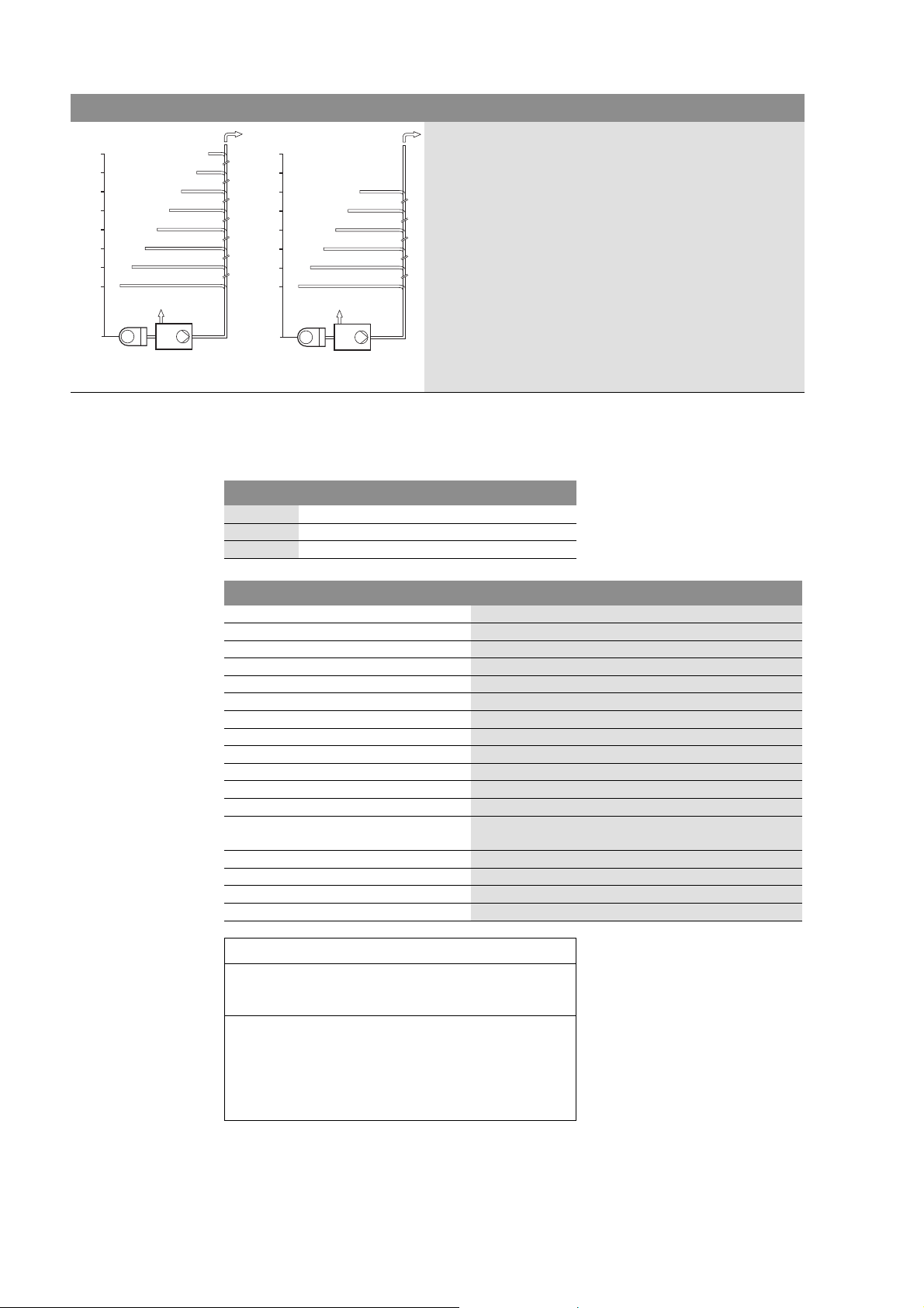
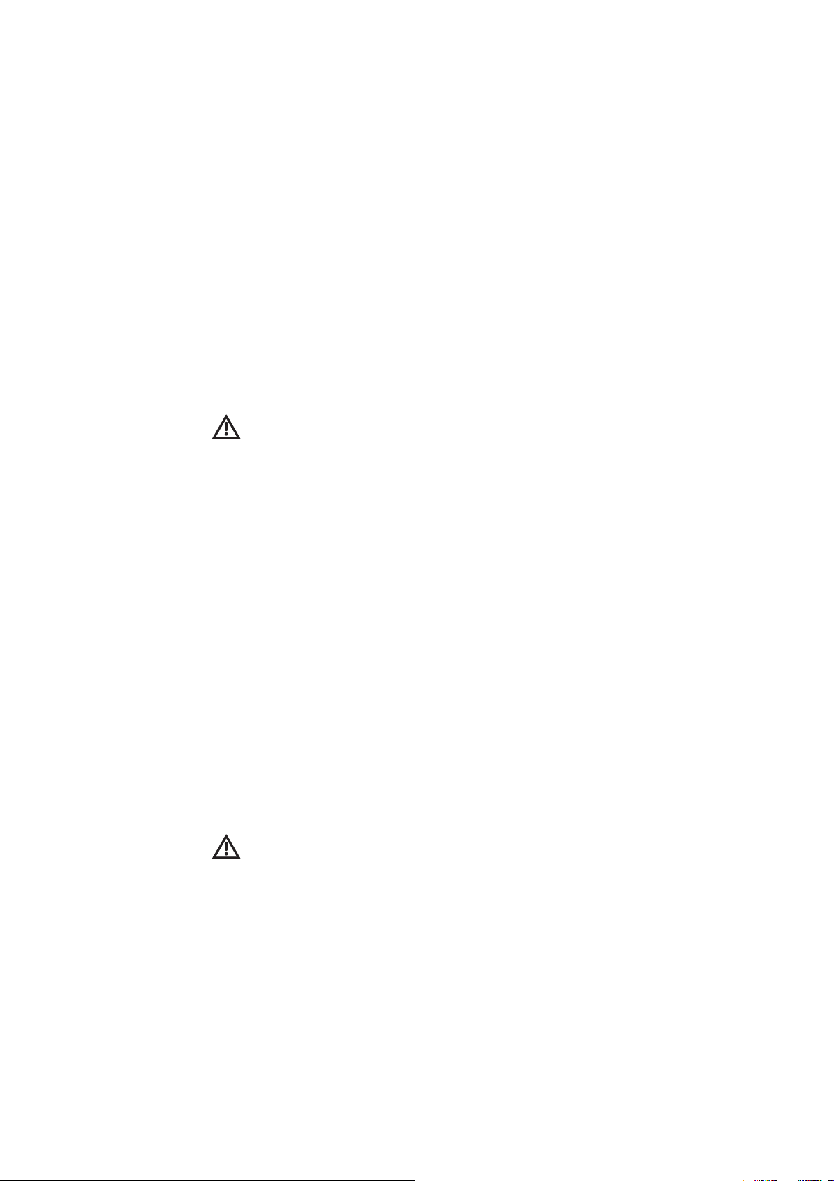
Fig. 1: Application limits
4,0
DN 32
2 m
11 m
20 m
29 m
39 m
48 m
57 m
3,5
3,0
2,5
2,0
1,5
1,0
0,5
0
H[m]
65 m
DN 25
4,0
3 m
7 m
11 m
15 m
19 m
3,5
3,0
2,5
2,0
1,5
1,0
0,5
0
H[m]
23 m
English
The flow rate in the pressure pipe must be at least 0.7 m/s. For
safe operation, the maximum geodesic delivery head of 4 mWS
must not be exceeded. Fig. 1 shows the resulting application
limits and delivery distances (maximum pressure pipe lengths DN
32 / DN 25) depending on the pipe diameter.
For best results, the pressure pipe should be laid first vertically
and then horizontally (including two 90° bends and an integrated
non-return valve).
When installed according to the regulations and properly used,
the unit complies with the EMC safety requirements of EU directive 89/336 EEC and is suitable for domestic use on the public
electricity mains.
Proper use includes compliance with the instructions in this
manual.
Any other use is considered improper.
5 Product information
5.1 Type key
Example: DrainLift XS-F
DrainLift Lifting unit
XS Size
-F Front-wall
5.2 Technical data
Connected voltage [V] 1~230, ± 10%
Power consumption P
1 [kW] 0,4
Rated current [A] 1,8
Mains frequency
Protection class
[Hz] 50
IP 24
Speed [¹/min] 2610
Operating mode
Max. total delivery head
[mWS] See name plate
S 3 30% (3 min. operation – 7 min. pause)
Max. permitted geodesic delivery head [mWS] 4
Max. volume flow
Max. fluid temperature
Gross volume
Dimensions incl. non-return valve
[m³/h] See name plate
[°C] 35
[l] 7,9
[mm] 515x168x410
(WxDxH)
Weight [kg] 6,5
Pressure port
Inlet ports
Ventilation
[DN] 32 (outer diameter AD 40)
[DN] 50, 100
[DN] 50
CE
WILO AG Dortmund
Nortkirchenstr. 100, 44263 Dortmund
07
EN 12050-3
DN 25 Sewage lifting unit for limited use
Lifting power - see rating plate
Installation and operating instructions Wilo-DrainLift XS-F 21
Noise level < 70 db(A)
Corrosion
protection
- inox/composite corrosion-resistant
materials
Please state all the information on the system name plate when ordering spare parts.
Page 8
English
8
9
7
4
1
4
15
14
13
12
2
5
5
5
2
3
6
11
2
10
10
19
18
17
16
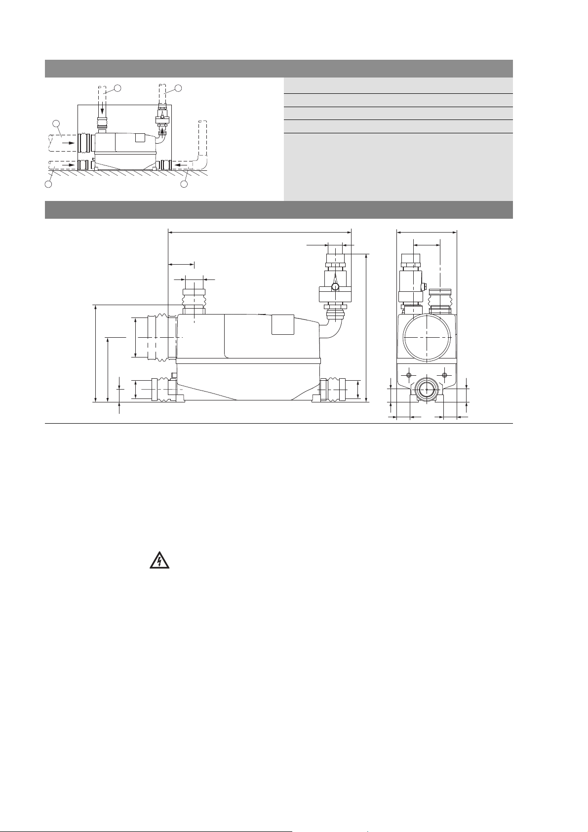
5.3 Scope of delivery
Complete DrainLift XS-F, with integrated alarm system and potential-free contact,
installed ready to plug in.
Fig. 2: Scope of delivery
1 1 pressure port discharge
elbow DN 32
2 3 sleeves DN 50
3 1 sleeve DN 100
4 2 hose clips 32-50
5 6 hose clips 40-60
6 2 hose clips 100-120
7 1 adapter joint 40 x 1 ¼"
8 1 adapter joint 40/50 x 1 ¼"
9 1 non-return valve 1 ¼" pressure pipe
10 1 non-return valve for inlet pipe DN 50
11 1 drain hose 600 mm with plug and hose clip
12 1 ventilation insert
13 1 active carbon filter
14 1 compensating orifice plate
15 1 ventilation grille
16 1 hanger bolt M8x200
17 1 wall plug S10
18 1 “Prohibited substances” sticker
19 1 installation and operating instructions
5.4 Accessories
Accessories must be ordered separately:
•Service hatch
•Gate valve 1¼"
• Alarm switchgear KAS
• Alarm switchgear DrainAlarm 2
For a detailed list and description see the catalogue/price list.
6Description and function
6.1 Description of the unit
An automatically operating small lifting unit (Fig. 3) including all required switching and
control mechanisms, with non-return valve, active carbon filter, elastic pressure port and
connections for a toilet, two additional drainage fixtures and a ventilation pipe.
The DrainLift XS-F small lifting unit is directly connected to the outflow bend of a wallhung toilet.
The direct toilet connection and the connections for additional drainage fixtures are on the
longitudinal sides of the unit, and the two ventilation ports are on the top of the tank. The
fluid flows out through an elastic, rotatable pressure pipe.
Ventilation takes place via the active carbon filter supplied into the installation room, or
odour-free via a ventilation pipe through the rough.
22 WILO AG 11/2007
Page 9
English
Ø110
Ø50
Ø50 75
168
73
515
Ø50
Ø50
37
37
37 37
35
180
271
410
Fig. 3: Connections
3
4
Dimensions
12
1 Pressure pipe
2 Ventilation pipe
3 Inlet for wall hung toilet, HT pipe DN 100
4 Inlet pipe for shower/bidet
5 Inlet pipe for washbasin
5
6.2 Function
The DrainLift XS-F has a level switch, which switches on the pump according to the water
level. It is switched off automatically after a set time.
The motor winding is protected by an overload safety device which automatically switches
off the pump and switches it on again after it has cooled down.
An integrated, mains-dependent alarm signal (buzzer) signals any operating faults which
occur. An additional potential-free contact (5 A/250 V) on the board can be used to forward the signal.
7 Installation and electrical connection
DANGER! Risk of fatal injury!
Incorrect installation and inexpert electrical connection can pose a risk of fatal injury.
• The installation and electrical connection may only be carried out by qualified personnel in accordance with the applicable regulations!
• Observe the regulations on the prevention of accidents!
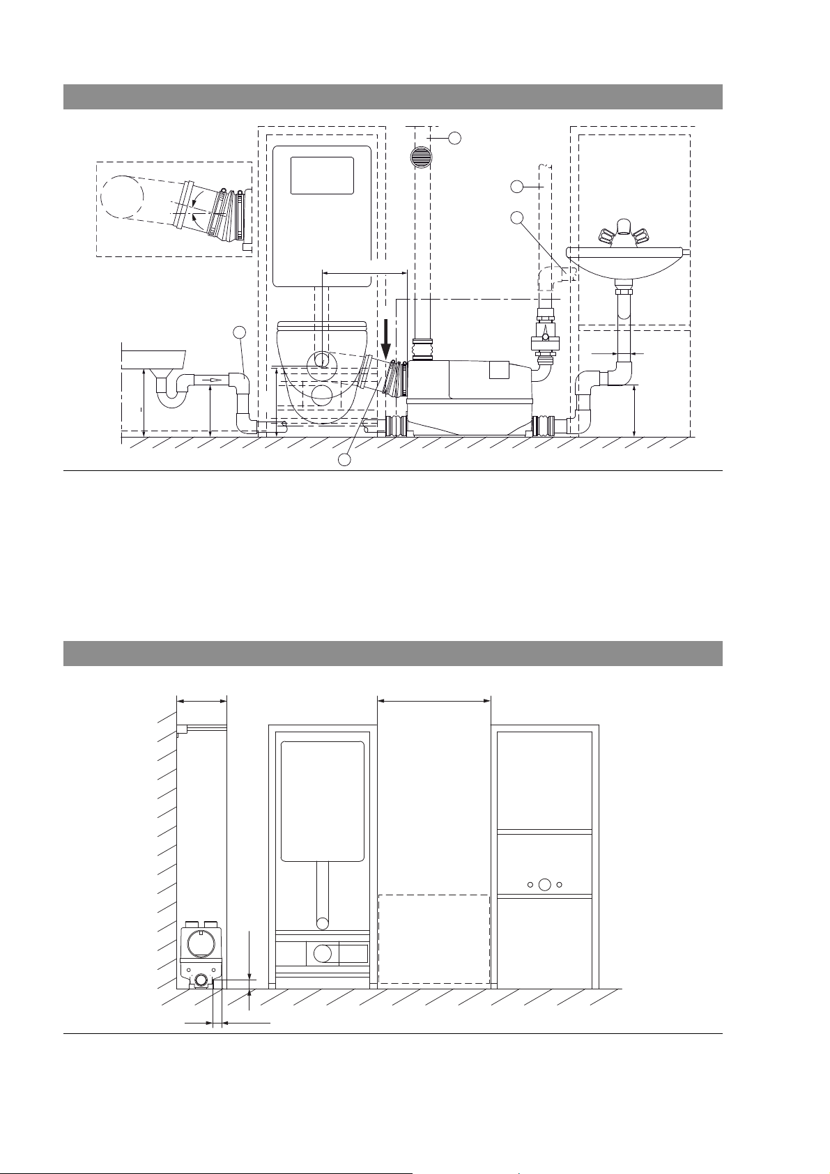
7.1 Preparing for installation
The DrainLift XS-F is designed for front wall installation (Fig. 4). The unit is installed directly
beside the module for a wall-hung toilet.
• The unit must be installed in a room protected from frost.
• The installation surface must be horizontal and flat.
• The lifting unit and its electrical connection (power plug) must remain accessible for maintenance after it is installed.
Installation and operating instructions Wilo-DrainLift XS-F 23
Page 10
English
2%
15°
max. 350
min. 180
Ø50
min. 180
220
>
220
5
2
3
1
4
A*
A*
Fig. 4: Front wall installation
7.1.1 Modules for front wall installation
The DrainLift XS-F can be combined with all commercially available front wall installation
systems. The main installation conditions for the unit are shown in Fig. 5. To guarantee
accessibility, there must be a service hatch of at least 500 x 400 mm. An installation kit for
making a service hatch is available as an accessory.
If the front wall depth is 200 mm and several modules are aligned on a floor-mounted rail
larger than 37 x 37 mm, a compensating plate may have to be placed under the unit. The
plate should not be too thick, in order to ensure a sufficient fall in the drain pipe of the toilet bowl. The shower must also be placed higher by the thickness of the plate.
Fig. 5: Modules for front wall installation
min. 180
min. 550
500 x 400
min. 37
max. 37
24 WILO AG 11/2007
Page 11

7.1.2 Inlet ports
The toilet connection (Fig. 4, Pos. 4) takes place directly with the outflow bend of the front
wall installation and an HT bend DN 100, 15 °C, and can be either to the right or the left of
the toilet basin.
CAUTION! Risk of damage!
Incorrect installation can result in damage.
The distance between the middle of the wall-hung toilet and the unit may not be more
than 350 mm, as otherwise malfunctions may occur.
Therefore, do not use an additional connecting pipe between the toilet outflow bend
and the unit.
The middle of the toilet outflow must be 220 mm above the installation level of the
unit.
As well as a wall-hung toilet, the unit can be connected to a washbasin, a shower and a
bidet; other connections are not permitted.
The tank has one port for additional DN 50 HT pipes on each longitudinal side, located
lower down, as well as two ports on the top of the tank.
The elastic connecting sleeves supplied for connecting the outflow pipe simplify installation and are required for reasons of noise prevention.
The inlet pipes from the shower and washbasin must be fitted with a bend (Fig. 4, Pos. 5)
as close as possible to the unit, if they are connected to the low ports on the longitudinal
sides. This bend must have a height of at least 180 mm between the bottom of the pipe
and the installation level, in order to prevent sewage containing faeces from flowing back
into the inlet pipe.
Installing the lifting unit before covering the frame makes it easier to inspect the connections.
English
7.1.3 Pressure pipe
Fig. 6: Pressure pipe connection
The on-site pressure pipe (Fig. 4, Pos. 1) DN 25 or DN 32 (minimum clear diameter 28 mm)
is connected via an S-shaped discharge elbow to the pressure outlet of the unit. The waste
water pressure pipes may be made of PVC, PP or PE-HD.
The pressure pipe should be laid without a fall. If laying it
with a fall to the transfer point is unavoidable, a wider pipe
should be laid from the highest point in order to prevent a lifting effect and associated malfunctions (Fig. 4, Pos. 2 and
Fig. 6-3).
Fasten the 1 ¼" non-return valve with a 40 x 1 ¼" adapter
directly to the S-shaped pressure pipe elbow, so that the
water flowing back after the pump is switched off is reduced
to a minimum and the valve can be easily accessed through
the inspection opening during maintenance
(Fig. 6-1).
7.1.4 Tank ventilation
CAUTION! Risk of damage!
Incorrect installation can result in damage.
Improperly installed tank ventilation can cause malfunctions.
The tank must be ventilated in order for the unit to work properly.
Installation and operating instructions Wilo-DrainLift XS-F 25
Page 12

English
min. 180
850
4
3
2
1
Fig. 7: Tank ventilation
Fig. 8: Fitting the tank ventilation
The ventilation insert can be positioned as in Fig. 4, Pos. 3
and Fig. 7. The filter insert can also be fed upwards or sideways through the front wall.
The tank is ventilated (Fig. 8) through an on-site HT pipe DN
50, which connects the ventilation insert (supplied) or a ventilation pipe through the roof to the unit. The unit is supplied
with an active carbon filter which reduces smells in the ventilation insert. Before installation, remove the foil. To change
the active carbon filter, simply remove the ventilation grille
from outside.
1 Ventilation insert with active carbon filter
2 Ventilation grille
3 Ventilation pipe (HT) DN 50
4 Connecting sleeve DN 50
Fig. 9: Hole for ventilation insert
+2
Ø76
850
Fig. 9 shows how to drill a hole 76 mm in diameter for installing the ventilation insert.
26 WILO AG 11/2007
Page 13

Fig. 10: Ventilation insert
8
7
6
4
3
2
1
5
1
2
English
Fig. 10 shows a cross-section through the finished wallmounted installation around the ventilation insert. If ventilation is through the roof, the ventilation insert and the active
carbon filter are not required.
1 HT pipe sleeve DN 50
2 Ventilation insert
3 Ventilation grille
4 Compensating orifice plate
5 Active carbon filter
6 Tiles
7 Tile adhesive
8 Moisture-proof board
7.2 Electrical connection
DANGER! Risk of fatal injury!
If the electrical installation is not properly carried out, there is a risk of fatal electric
shock.
• Always have the electrical connection performed by a qualified electrician.
• For installation in bath and shower rooms, observe the relevant local regulations [e.g.
VDE 0100 Part 701 in Germany].
The unit is delivered ready to plug in and may only be connected to standard safety
sockets.
• The current type and voltage of the mains connection must correspond to those stated on
the name plate,
• Mains fuse: 10 A, slow-blow
• Earth the unit according to the regulations.
7.2.1 Mains connection
Fig. 11: Position of the safety socket
There are two options for positioning the safety socket:
1 Within the front wall installation, behind the cover
of the maintenance hatch (Fig. 11, Pos. 1). The
inspection hatch must be opened in order to
respond to an alarm by pulling out the mains plug.
2 Outside the front wall installation, near the main-
tenance hatch (Fig. 11, Pos. 2). There is immediate
access to the main plug for responding to an alarm
or switching off the unit in an emergency.
Installation and operating instructions Wilo-DrainLift XS-F 27
Page 14

English
Fig. 12: Installing the safety socket
7.2.2 Potential-free contact
Fig. 13: Switching diagram
P1
For installation outside the front wall installation, a flushmounted cavity wall socket with a cut-out base is required
(Fig. 12). It is covered with a commercially available cooker
socket from any manufacturer. When the insert for the
cooker socket is removed, the mains plug can be passed
through for initial connection and maintenance.
The device has a potential-free normally open alarm contact
on the motor board (Fig. 13) for forwarding alarms:
Terminals 40 / 41
Max. contact load: 5 A/250 V.
K2
40 41
max.
5A/250V
K1
1
1
4332
HA HI
M
PE
CB
1~230V/50Hz
Note for using screwless terminals:
Open the terminal with a screwdriver and push the cable into
the lower opening.
Each terminal can only hold one conductor.
40 4
28 WILO AG 11/2007
Page 15

7.3 Installation
4 5
~
480
~
275
35
~
235
500
3
1
2
35
180
400
Before starting installation, check the scope of delivery of the unit and the local installation
conditions. .
Fig. 14: Pre-mounting the connections
Fig. 15: Buoyancy protection
English
The inlet and pressure pipes must be pre-mounted as illustrated (Fig. 14) in the room where the unit is to be installed. If
the unit is mounted to the right of the toilet, assembly is the
reverse of the illustration.
1 Pressure pipe
2 Ventilation pipe
3 Inlet for wall-hung toilet
4 Inlet pipe for shower/bidet
5 Inlet pipe for washbasin
Fig. 16: Preparing the connecting ports of the unit
Ø40
The DrainLift XS-F cannot be flooded, which means the
installation site must be secure against flooding. EN 120503 requires that sewage lifting units must be protected
against buoyancy (Fig. 15). Place the unit in the installation
room and align it to the pipes to be connected. Use a long 10
mm stone bit to drill a marking just above the tank (not
above the detachable hood), so that the hanger bolt to be
mounted later will touch or only have a slight gap to the tank.
After drilling, take the unit out of the maintenance hatch and
finish drilling the hole. Then put in the wall plug. Only fit the
hanger bolt after
you have installed the system.
Open the connecting ports for the drainage fixtures in addition to the wall-hung toilet (shower, washbasin and / or
bidet) and for the ventilation ports using a 40 mm hole saw
(Fig. 16). Then deburr the holes.
CAUTION! Risk of damage!
Remove the cut-out circle; do not leave it in
the tank.
Installation and operating instructions Wilo-DrainLift XS-F 29
Page 16

English
max. Ø9
4
5
3
12
500
400
Fig. 17: Shower inlet non-return valve (not permitted in Germany)
The 40 mm non-return valve supplied (Fig. 17) is inserted in
the lower inlet opening of the shower connection via the
guide grooves until it snaps in.
CAUTION! Risk of malfunctions!
Malfunctions will occur if the valve is incorrectly fitted
• The valve hinge must face upwards (check the
condition on delivery).
• The valve must open towards the inside of the
tank.
Fig. 18: Emergency drain connection
NOTE: The PVC hose with plug supplied can be
attached to the tank for simple draining in emergencies (Fig. 23). Drill the 13 mm port on the bottom of the tank with a spiral drill (max. Ø 9 mm)
(Fig. 18). Push in the hose and fasten it with the
hose clip (1.5 Nm tightening torque). Make sure
that the drain opening of the hose is securely
sealed with the plug.
Fig. 19: Mounting the connecting sleeves
Before installing the unit, fasten the DN 50 and DN 100 connecting sleeves to the inlet pipes using the clips (supplied)
(Fig. 19).
Make sure they are correctly seated and do not leak.
30 WILO AG 11/2007
Page 17

Fig. 20: Installing the unit
4
5
3
12
Fig. 21: Prohibited substances
English
Place the unit in the room w here it is to be instal led, li ne it up
and fit the hanger bolt for buoyancy protection. Then fit the
connecting sleeves to the tank ports using the clips. Fit the
discharge elbow between the pressure pipe and the pressure
outlet of the unit and fasten it with the clips (Fig. 20).
Make sure all clip connections they are correctly seated and
do not leak.
Attach the sticker warning of prohibited substances
(Fig. 21).
Attach the sticker supplied showing instructions (symbols)
for the user of the toilet somewhere clearly visible, for
example above the toilet lid or on the inside of the toilet lid.
CAUTION! Risk of damage!
Putting in prohibited materials can cause malfunctions, damage the unit and invalidate the
warranty.
8 Commissioning
•Plug in the safety plug
• On initial use, flush the toilet twice
• Check all pipe connections for leaks and tighten the clips if necessary
• Adjust the cistern of the toilet so that the flush volume is not less than 6 litres of water
Operation
NOTE: After using mild, commercially available detergents, flush several times so that no
traces of the cleaning agent are left in the unit.
CAUTION! Risk of damage!
The unit can be damaged by incorrectly fastened toilet cleaners.
Fasten holders for toilet cleaners very securely to the toilet bowl to ensure that they
are not flushed into the unit.
9 Maintenance and cleaning
Maintenance and repairs may only be carried out by qualified personnel
WARNING! Risk of infection!
All maintenance must be carried out wearing suitable safety clothing (gloves) in order
to prevent the risk of infection.
DANGER! Risk of fatal injury!
There is a risk of fatal electric shock when working on electrical equipment.
• Before all maintenance and repair work, switch off the unit from the power supply and
make sure it cannot be switched on by unauthorised persons.
• Disconnect the power plug!
• Work on the electrical part of the unit may only be carried out by a qualified electrician.
Installation and operating instructions Wilo-DrainLift XS-F 31
Page 18

English
When properly used, the DrainLift XS-F requires little maintenance. Nevertheless, the unit
should be inspected at least once a year:
• Check all connections for leaks.
• Check the active carbon filter in the ventilation insert and replace it.
9.1 Remove obstructions after alarms
Disconnect the power plug before any work on the unit!
• Take off the cover of the inspection opening.
• If the pump is obstructed or blocked, you can free it with a screwdriver without removing
any other parts.
Fig. 22: Freeing the motor shaft
• Remove the plug in the middle of the cover cap.
• Insert a long screwdriver through the hole in the cover
(Fig. 22).
• Find the slot in the motor shaft by slightly turning it and
remove the obstruction by forcefully turning the shaft in
both directions.
• Check the pump by temporarily connecting the power
plug.
• If the pump does not run as normal, remove the pump unit.
Fig. 23: Draining the unit
9.1.1 Dismantling the pump unit
Emergency drainage
Before dismantling, you must drain the water from the toilet bowl and the unit. Use an
electric drill (n > 2000/min clockwise) and a long screwdriver to drive the pump using the
slot in the motor shaft and carry out emergency draining.
If the supplied PVC hose was fitted during assembly
(Fig. 18 / 23), the accumulated water can be easily drained in
an emergency.
The water is drained out through the hose into a flat receptacle.
The hose is then sealed with the plug.
For the rest of the work, the tank remains installed in the wall. Only the pump unit has to
be removed.
32 WILO AG 11/2007
Page 19

English
Fig. 24: Removing the pump unit
1
3
2
4x
5
1 Remove the screw from the cover.
2 Push the cover slightly towards the pressure pipe
until it snaps out.
3 Lift off the cover.
4 Release the clips of the discharge elbow on the
pressure pipe and pull off the discharge elbow.
5 Undo the four screws on the corners of the pump
unit and lift it out of the tank.
4
• Remove any foreign matter from the tank or the pump through the suction opening and, if
necessary, clean the parts and the opening to the blockage pressure switch.
• Carefully reassemble the unit in the reverse order.
CAUTION! Risk of damage!
Incorrect reassembly can cause damage to the product.
• Before reassembly, generously grease the O-ring and the seat on the tank, for example
using petroleum jelly.
• Make sure the O-ring is correctly seated on the pump unit during reassembly.
• P us h th e p ump un it b y h and in to t he sea l s eat an d ha nd -ti gh ten the s cr ews cr oss wi se. First
turn them slightly anticlockwise to find the thread.
9.2 Installing / changing the active carbon filter
The active carbon filter (supplied) must be installed when ventilation through the roof is
not possible. The filter should be changed at least once a year, as well as after malfunctions
where water escapes, or when smells accumulate.
• To install or change the filter, take the ventilation grille off the ventilation housing.
• Take out the old filter and insert the new filter (after removing the foil) into the ventilation
insert as far as it will go, to the same position as the old filter (Fig. 8).
• The push the ventilation grille back on.
Installation and operating instructions Wilo-DrainLift XS-F 33
Page 20

English
10 Faults, causes and remedies
Faults may only be repaired by qualified personnel!
Fault Cause Remedy
Unit will not start,
Water remains in
toilet bowl.
Water only drains very slowly from
the toilet bowl.
Pump switches on frequently
after normal delivery.
Noisy operation.
Unit alarm sounds. Running time too long (pressure pipe or
Occasional obstructions, no
audible sipping mode.
Power failure. Check mains voltage.
Faulty fuse. Replace fuse.
Mains cable damaged. Attention! The special cable may only be
Unit overloaded; motor shut down. Unit switches on again after cooling down,
Motor defective. Have after-sales service replace pump unit.
Impeller blocked. See 9.1
Obstruction in siphon of toilet bowl.
Obstruction in front of tank in toilet inlet.
Obstruction in pump suction opening due to
too much paper and not enough water.
Delivery head too high. See 7.1.3, pressure pipe.
Cistern valve leaks, water constantly flows
through the toilet bowl to the unit.
Leaky or defective non-return valve; after
pumping water returns from the pressure
pipe to the unit.
Obstruction in the tank in front of the pump,
so that water is only pumped out at short
intervals.
Defective level switch on the unit. Call after-sales service.
Foreign matter in the pump. See 9.1
pump inlet opening blocked).
Water level in tank too high (pump blocked
or obstructed).
Water level in tank too high (level switch
defective).
No homogenisation of fluid. Call after-sales service.
replaced by after-sales service or a qualified
electrician.
avoid overload if possible.
Check the amount of water for flushing in
the toilet cistern and set it to 9 litres or the
maximum quantity. If more water than usual
remains in the toilet bowl, flush again and
repeat as long as it is pumped out.
See 9.1
Check the cistern valve.
Check the non-return valve; if there is no
backflow in the toilet bowl, flush at intervals
several times.
See 9.1
See 9.1
See 9.1
Call after-sales service.
If the malfunction cannot be rectified, call a specialist or the nearest Wilo agent or
after-sales support.
11 Spare parts
Spare parts can be ordered from local specialists or Wilo after-sales service.
To prevent queries or faulty orders, please state all the information on the name plate when
ordering.
Subject to change without prior notice
34 WILO AG 11/2007
Page 21

7.3 Монтаж
4 5
~
480
~
275
35
~
235
500
3
1
2
35
180
400
Перед началом монтажа необходимо проверить объем поставки установки и
местные условия монтажа.
Рис. 14. Предварительный монтаж соединений
Рис. 15. Защита от действия подъемной силы
Русский
В подготовленном помещении для монтажа установки
следует смонтировать подводящие трубопроводы и
напорный трубопровод согласно приведенной схеме
(рис. 14). При монтаже установки справа от унитаза
следует для монтажа трубопроводов следует
использовать зеркальное отражение схемы.
1 Напорный трубопровод
2 Вентиляционный трубопровод
3 Подводящий патрубок унитаза,монтируемого
за наружной стеной здания
4 Подводящий трубопровод от душа или биде
5 Подводящий трубопровод от умывальника
Рис. 16. Подготовка соединительных патрубков установки
Ø40
Установка DrainLift XS-F не должна подвергаться
затоплению, поэтому место установки необходимо
защитить от затопления. Согласно требованиям
нормативов EN12050-3 установки для отведения
сточных вод, содержащих фекалии, должны быть
защищены от действия подъемной силы (рис. 15).
Следует установить установку на месте монтажа и
выровнять ее в соответствии с расположением
подключаемых трубопроводов. Длинным сверлом по
бетону ø 10 мм непосредственно
над резервуаром (не
над съемной крышкой!) сделать отметку на стене таким
образом, чтобы установленный затем в этом месте
винт-шуруп касался резервуара или был расположен с
небольшим зазором над резервуаром. После
засверливания следует убрать установку через люк для
технического обслуживания и окончательно
просверлить отверстие. Затем необходимо вставить
дюбель. Монтаж винтатолько после
монтажа установки.
шурупа следует выполнять
Соединительные патрубки для дополнительных
санитарно-технических объектов помимо унитаза,
монтируемого за наружной стеной здания (душевой
кабины, умывальника и / или биде), а также вентиляционные патрубки необходимо открыть при помощи
кольцевой пилы ø 40 мм (рис. 16). После этого следует
удалить заусенцы с отверстий.
ВНИМАНИЕ! Опасность повреждения
оборудования!
Необходимо удалить вырезанные круги; не
допускается оставлять
их в резервуаре.
Инструкция по монтажу и эксплуатации Wilo-DrainLift XS-F 97
Page 22

Русский
max. Ø9
4
5
3
12
500
400
Рис. 17. Обратный клапан ввода от душевой кабины (в Германии использование не допускается)
Входящий в объем поставки обратный клапан Ш 40 мм
(рис. 17) вставить в нижнее входное отверстие
подключения душевой кабины в направляющие пазы до
фиксации.
ВНИМАНИЕ! Опасность нарушения работы
оборудования!
Неправильный монтаж клапана приводит к
нарушению работы
• Шарнир клапана должен быть расположен
наверху (проверить состояние при
поставке)
• Клапан должен открываться внутрь
резервуара.
Рис. 18. Подключение аварийного слива
УКАЗАНИЕ.
Для облегчения аварийного слива
накопившихся в резервуаре сточных вод
можно подключить к резервуару
прилагаемый шланг из ПВХ с заглушкой
(рис. 23). Для этого необходимо
просверлить отверстие в патрубке
расположенном в нижней части
резервуара, при помощи винтового
сверла (макс.
ø 9 мм) (рис. 18). Надеть
шланг и закрепить его хомутом (момент
затяжки 1,5 Н·м). Следить за тем, чтобы
сливное отверстие шланга было
надежно закрыто заглушкой.
ø 13,
Рис. 19. Монтаж соединительных манжет
Перед монтажом установки необходимо закрепить
соединительные манжеты DN 50 и DN 100 на
подводящих трубопроводах при помощи хомутов
(входят в объем поставки) (рис. 19).
При этом необходимо следить за правильностью и
герметичностью посадки.
98 WILO AG 11/2007
Page 23

Рис. 20. Монтаж установки
4
5
3
12
Рис. 21. Недопустимые материалы
Установить установку на место монтажа, выровнять и
установить винт-шуруп болт для защиты от действия
подъемной силы. После этого закрепить
соединительные манжеты на патрубках резервуара при
помощи хомутов. Установить выходной отвод между
напорным трубопроводом и напорным патрубком
установки и закрепить при помощи хомутов (рис. 20).
При выполнении всех соединений с использованием
хомутов
следить за надежной и герметичной посадкой.
Прикрепить наклейку с указаниями в отношении
недопустимых материалов (рис. 21).
Входящую в комплект принадлежностей наклейку с
указаниями для пользователей (символическими
обозначениями) прикрепить в месте хорошей
видимости для пользователей туалета, например на
крышке унитаза или на внутренней стороне крышки
унитаза.
ВНИМАНИЕ! Опасность повреждения
оборудования!
Попадание недопустимых материалов
приводит к нарушению работы и
повреждению
изделия, и может привести к
отказу в гарантийном обслуживании.
Русский
8 Ввод в эксплуатацию
• Вставить штепсельную вилку с защитным контактом в розетку.
• При первом вводе в эксплуатацию нажать 2 раза смыв туалета.
• Проверить герметичность всех соединений трубопроводов. При необходимости
подтянуть хомуты.
• Смывной бачок туалета настроить таким образом, чтобы объем смывной воды был
не меньше 6 л.
Эксплуатация
УКАЗАНИЕ. После использования обычных мягких моющих средств несколько раз
смыть воду, чтобы в установке не оставалось остатков моющего средства.
ВНИМАНИЕ! Опасность повреждения оборудования!
Опасность повреждения в результате ненадлежащего крепления чистящих
средств долговременного действия для туалета.
Чистящие средства для туалета должны быть надежно закреплены на унитазе,
чтобы они не могли быть смыты водой в установку.
9 Техническое обслуживание и очистка
Работы по техническому обслуживанию и ремонту должны выполняться только
квалифицированными специалистами.
ОСТОРОЖНО! Опасность инфекции!
При проведении работ по техническому обслуживанию следует надевать
соответствующую защитную одежду (защитные перчатки), чтобы избежать
возможной опасности воздействия инфекции.
ОПАСНО! Опасно для жизни!
При проведении работ с электрооборудованием существует опасность
поражения электрическим током.
Инструкция по монтажу и эксплуатации Wilo-DrainLift XS-F 99
Page 24

Русский
• При проведении любых работ по техническому обслуживанию и ремонту
необходимо отключить установку от источника электропитания и обеспечить
защиту от несанкционированного включения.
• Вынуть штепсельную вилку из розетки!
• Работы с электрическими компонентами установки должны выполняться только
квалифицированными электриками.
• При использовании по назначению установка DrainLift XS-F не требует частого
технического обслуживания. Тем не менее необходимо проверять установку не
реже одного раза в год.
• Проверить герметичность всех соединений.
• Проверить и заменить фильтр с активированным углем в вентиляционной насадке.
9.1 Устранение засорения при срабатывании аварийной сигнализации
Перед проведением каких-либо работ с установкой необходимо вынуть
штепсель из розетки.
• Снять крышку люка для технического обслуживания.
• Если
восстановлена при помощи отвертки без дальнейшего демонтажа.
Рис. 22. Разблокирование вала мотора
насос вращается с трудом или заблокирован, его работа может быть
• Вынуть заглушку, установленную в средней части
защитной крышки.
• Вставить длинную плоскую отвертку в отверстие в
защитной крышке (рис. 22).
• Путем осторожного вращения найти шлиц в валу
мотора и для устранения блокировки повернуть вал с
усилием в обоих направлениях.
• Проверить работу насоса путем кратковременного
подключения штепсельной вилки.
• Если насос не
работает надлежащим образом,
необходимо демонтировать узел насоса.
9.1.1 Демонтаж узла насоса
Аварийный слив
Перед дальнейшим демонтажом следует устранить обратный подпор воды в унитазе и
установке. При помощи дрели (частота вращения> 2000 об./мин., вращение по часовой
стрелке) и длинной насадки в виде отвертки
можно привести насос в действие,
используя шлиц вала мотора, и тем самым выполнить аварийный слив.
100 WILO AG 11/2007
Page 25

Русский
Рис. 23. Удаление воды из установки
При выполнении дальнейших работ резервуар остается установленным в стене.
Необходимо демонтировать только узел насоса.
Если при монтаже к резервуару был подключен
прилагаемый шланг из ПВХ (рис. 18 / 23), остатки воды
могут быть легко удалены в случае аварии.
Для этого следует слить остатки воды через шланг в
плоский сосуд.
После этого снова следует закрыть шланг заглушкой.
Рис. 24. Демонтаж узла насоса
1
3
2
4x
5
1 Отвинтить винт защитной крышки.
2 Легко потянуть крышку в направлении
напорного трубопровода до освобождения
крепления.
3 Снять крышку, потянув ее вверх.
4 Ослабить хомуты выходного отвода напорного
патрубка и снять выходной отвод.
5 Отвинтить четыре винта в углах узла насоса и
снять узел насоса с резервуара.
4
Инструкция по монтажу и эксплуатации Wilo-DrainLift XS-F 101
Page 26

Русский
• Удалить посторонние предметы из резервуара или из насоса через отверстие
всасывания; при необходимости очистить детали и отверстие к реле давления,
срабатывающему при засорении.
• Аккуратно выполнить монтаж установки в обратной последовательности.
ВНИМАНИЕ! Опасность повреждения оборудования!
Неправильный повторный монтаж может привести к повреждению изделия.
• Перед повторной сборкой необходимо тщательно смазать уплотнительное
кольцо, а также место посадки на резервуаре, например, вазелином.
• При повторном монтаже необходимо следить за правильной посадкой
уплотнительного кольца на узле насоса.
• Нажать на узел насоса рукой, чтобы установить его на месте посадки уплотнения, и
плотно затянуть рукой винты (крест-накрест). При этом сначала для обнаружения
сформированной резьбы следует слегка поворачивать винты против часовой
стрелки.
9.2 Установка / замена фильтра с активированным углем
Фильтр с активированным углем (прилагается) необходимо установить, если
удаление воздуха через крышу невозможно. Замена фильтра должна выполняться
после неисправностей, сопровождающихся выходом воды через фильтр, и при
появлении неприятного запаха, но не реже 1 раза в год.
• Для установки или замены
следует снять вентиляционную решетку с корпуса
вентиляционной насадки.
• Удалить старый фильтр, вставить новый фильтр (предварительно сняв пленку) в
вентиляционную насадку до упора на место старого фильтра (рис. 8).
• По окончании снова установить вентиляционную решетку.
102 WILO AG 11/2007
Page 27

10 Неисправности, причины и способы устранения
Устранение неисправностей может выполняться только квалифицированными
специалистами.
Неисправности Причины Способы устранения
Русский
Установка не запускается,
вода остается в
чаше унитаза.
Вода из унитаза уходит
слишком медленно.
Частое включение установки
после нормального цикла
подачи.
Повышенный уровень шума при
работе.
Срабатывание звуковой
сигнализации установки.
Периодическое засорение, нет
звука работы с подсосом
воздуха.
Отключение электроэнергии. Проверить сетевое напряжение.
Неисправность предохранителей. Заменить предохранители.
Поврежден кабель питания от сети. ВНИМАНИЕ! Специальный кабель может
быть заменен только специалистом
технического отдела или электриком.
Перегрузка установки. Мотор отключен
защитой от перегрузки.
Неисправен мотор. Вызвать специалистов технического
Рабочее колесо заблокировано. См. пункт 9.1
Засорение сифона унитаза.
Засорение в передней части резервуара у
подводящего патрубка унитаза.
Засорение отверстия всасывания насоса
(слишком много бумаги и слишком мало
воды).
Высота подачи слишком велика. Обратиться в технический отдел.
Негерметичность клапана смывного
бачка, постоянная подача воды в
установку из унитаза.
Негерметичность или неисправность
обратного клапана, после цикла
откачивания вода попадает обратно в
насос из напорного трубопровода.
Засорение в резервуаре перед насосом
— вода откачивается с небольшими
интервалами.
Неисправность переключателя уровня
установки.
Посторонние предметы в насосе. См. пункт 9.1
Слишком длительное время работы
(засорение напорного трубопровода или
отверстия всасывания насоса).
Слишком высокий уровень воды в
резервуаре (насос заблокирован или
засорен).
Слишком высокий уровень воды в
резервуаре (неисправность
переключателя уровня).
Отсутствие гомогенизации
перекачиваемой среды.
После охлаждения происходит
повторное включение установки; по
возможности следует избегать
перегрузки.
отдела для замены узла насоса.
Проверить объем смыва в смывном бачке
унитаза и при необходимости установить
объем 9 л или максимальный объем.
Если в чаше унитаза остается не больше
воды, чем обычно, смыть еще раз и при
необходимости повторить до полного
откачивания воды.
См. пункт 9.1
Проверить клапан смывного бачка.
Проверить обратный клапан. При
отсутствии обратного подпора в чаше
унитаза повторить смыв несколько раз с
интервалом.
См. пункт 9.1
Обратиться в технический отдел.
См. пункт 9.1
См. пункт 9.1
Обратиться в технический отдел.
Обратиться в технический отдел.
Если устранить неисправность не удается, следует обратиться в мастерскую по
ремонту систем водоснабжения или в ближайший технический отдел или
представительство компании Wilo.
Инструкция по монтажу и эксплуатации Wilo-DrainLift XS-F 103
Page 28

Русский
11 Запчасти
Для заказа запасных частей следует обращаться к местным специалистам по
обслуживанию систем водоснабжения и / или в технический отдел компании Wilo.
Во избежание дополнительных уточнений и ошибочного заказа при каждом заказе
следует указывать все данные, приведенные на фирменной табличке.
Возможны технические изменения !
104 WILO AG 11/2007
Page 29

D EG - Konformitätserklärung
GB EC – Declaration of conformity
F Déclaration de conformité CEE
Hiermit erklären wir, dass die Bauarten der Baureihe :
DrainLift XS-F
Herewith, we declare that this product:
Par le présent, nous déclarons que cet agrégat :
in der gelieferten Ausführung folgenden einschlägigen Bestimmungen entspricht:
in its delivered state comply with the following relevant provisions:
est conforme aux dispositions suivants dont il relève:
Elektromagnetische Verträglichkeit - Richtlinie 89/336/EWG
Electromagnetic compatibility - directive
i.d.F/ as amended/ avec les amendements suivants:
Compatibilité électromagnétique- directive
91/263/EWG
92/31/EWG
93/68/EWG
Niederspannungsrichtlinie 2006/95/EG
Low voltage directive
Direction basse-tension
Bauproduktenrichtlinie 89/106/EWG
Construction product directive
i.d.F/ as amended/ avec les amendements suivants :
Directive de produit de construction
93/68/EWG
Angewendete harmonisierte Normen, insbesondere:
EN 12050-3
Applied harmonized standards, in particular:
EN 50366
Normes harmonisées, notamment:
EN 55014-1/2
EN 61000-3-2/3
EN 60335-1
EN 60335-2-41
Dortmund, 09.07.2007
Erwin Prieß
Quality Manager
WILO AG
Nortkirchenstraße 100
44263 Dortmund
Document: 2088067.2
Page 30

NL
EG-verklaring van overeenstemming
Hiermede verklaren wij dat dit aggregaat in de
geleverde uitvoering voldoet aan de volgende
bepalingen:
Elektromagnetische compatibiliteit 89/336/EEG
als vervolg op 91/263/EEG, 92/31/EEG, 93/68/EEG
EG-laagspanningsrichtlijn 2006/95/EG
Bouwproductenrichtlijn 89/106/EEG als vervolg
op 93/86/EEG
Gebruikte geharmoniseerde normen, in het bijzonder:
1)
I
Dichiarazione di conformità CE
Con la presente si dichiara che i presenti prodotti
sono conformi alle seguenti disposizioni e
direttive rilevanti:
Compatibilità elettromagnetica 89/336/CEE e
seguenti modifiche 91/263/CEE, 92/31/CEE,
93/68/CEE
Direttiva bassa tensione 2006/95/EG
Direttiva linee guida costruzione dei prodotti
89/106/CEE e seguenti modifiche 93/68/CEE
Norme armonizzate applicate, in particolare:
1)
E
Declaración de conformidad CE
Por la presente declaramos la conformidad del
producto en su estado de suministro con las
disposiciones pertinentes siguientes:
Directiva sobre compatibilidad electromagnética
89/336/CEE modificada por 91/263/CEE,
92/31/CEE, 93/68/CEE
Directiva sobre equipos de baja tensión
2006/95/EG
Directiva sobre productos de construcción
89/106/CEE modificada por 93/68/CEE
Normas armonizadas adoptadas, especialmente:
1)
P
Declaração de Conformidade CE
Pela presente, declaramos que esta unidade no
seu estado original, está conforme os seguintes
requisitos:
Compatibilidade electromagnética 89/336/CEE
com os aditamentos seguintes 91/263/CEE,
92/31/CEE, 93/68/CEE
Directiva de baixa voltagem 2006/95/EG
Directiva sobre produtos de construção
89/106/CEE com os aditamentos seguintes
93/68/EWG
Normas harmonizadas aplicadas, especialmente:
1)
S
CE- försäkran
Härmed förklarar vi att denna maskin i levererat
utförande motsvarar följande tillämpliga
bestämmelser:
EG–Elektromagnetisk kompatibilitet – riktlinje
89/336/EWG med följande ändringar
91/263/EWG, 92/31/EWG, 93/68/EWG
EG–Lågspänningsdirektiv 2006/95/EG
EG-Byggmaterialdirektiv 89/106/EWG med
följande ändringar 93/68/EWG
Tillämpade harmoniserade normer, i synnerhet:
1)
N
EU-Overensstemmelseserklæring
Vi erklærer hermed at denne enheten i utførelse
som levert er i overensstemmelse med følgende
relevante bestemmelser:
EG–EMV–Elektromagnetisk kompatibilitet
89/336/EWG med senere tilføyelser:
91/263/EWG, 92/31/EWG, 93/68/EWG
EG–Lavspenningsdirektiv 2006/95/EG
Byggevaredirektiv 89/106/EWG med senere
tilføyelser 93/68/EWG
Anvendte harmoniserte standarder, særlig:
1)
FIN
CE-standardinmukaisuusseloste
Ilmoitamme täten, että tämä laite vastaa
seuraavia asiaankuuluvia määräyksiä:
Sähkömagneettinen soveltuvuus 89/336/EWG
seuraavin täsmennyksin 91/263/EWG 92/31/EWG,
93/68/EWG
Matalajännite direktiivit: 2006/95/EG
EU materiaalidirektiivi 89/106/EWG seuraavin
täsmennyksin 93/68/EWG
Käytetyt yhteensovitetut standardit, erityisesti:
1)
DK
EF-overensstemmelseserklæring
Vi erklærer hermed, at denne enhed ved levering
overholder følgende relevante bestemmelser:
Elektromagnetisk kompatibilitet: 89/336/EWG,
følgende 91/263/EWG, 92/31/EWG, 93/68/EWG
Lavvolts-direktiv 2006/95/EG
Produktkonstruktionsdirektiv 98/106/EWG
følgende 93/68/EWG
Anvendte harmoniserede standarder, særligt:
1)
H
EK. Azonossági nyilatkozat
Ezennel kijelentjük,hogy az berendezés az
alábbiaknak megfelel:
Elektromágneses zavarás/türés: 89/336/EWG és
az azt kiváltó 91/263/EWG, 92/31/EWG,
93/68/EWG
Kisfeszültségü berendezések irány-Elve:
2006/95/EG
Építési termékek irányelv 98/106/EWG és az azt
kiváltó 93/68/EWG
Felhasznált harmonizált szabványok, különösen:
1)
CZ
Prohlášení o shodĈ EU
Prohlašujeme tímto, že tento agregát v dodaném
provedení odpovídá následujícím pįíslušným
ustanovením:
SmĈrnicím EU–EMV 89/336/EWG ve sledu
91/263/EWG, 92/31/EWG, 93/68/EWG
SmĈrnicím EU–nízké napĈtí 2006/95/EG
SmĈrnicím stavebních produktĽ 89/106/EWG ve
sledu 93/68/EWG
Použité harmonizaüní normy, zejména:
1)
PL
Deklaracja Zgodnoıci CE
Niniejszym deklarujemy z peğnö odpowiedzialnosciö
Ņe dostarczony wyrób jest zgdony z nastĆpujöcymi
dokumentami:
Odpowiednioıø elektromagnetyczna 89/336/EWG
ze zmianö 91/263/EWG, 92/31/EWG, 93/68/EWG
Normie niskich napiĆø 2006/95/EG
Wyroby budowlane 89/106/EWG ze zmianö
93/68/EWG
Wyroby sö zgodne ze szczegóğowymi normami
zharmonizowanymi:
1)
RUS
ƟǀDždžƻǑǃǚ lj njljljǍƽǀǍnjǍƽǃǃ ƠƽNjljNJǀDŽnjDžǃLJ
LjljNjLJƻLJ
ƨƻnjǍljǚǔǃLJ ƿljDžǎLJǀLjǍljLJ ǂƻǚƽdžǚǀLJ, ǒǍlj ƿƻLjLjǖDŽ
ƻƾNjǀƾƻǍ ƽ ǀƾlj ljƼǕǀLJǀ NJljnjǍƻƽDžǃ njljljǍƽǀǍnjǍƽǎǀǍ
njdžǀƿǎǙǔǃLJ LjljNjLJƻǍǃƽLjǖLJ ƿljDžǎLJǀLjǍƻLJ:
ƸdžǀDžǍNjljLJƻƾLjǃǍLjƻǚ ǎnjǍljDŽǒǃƽljnjǍǗ 89/336/EWG nj
NJljNJNjƻƽDžƻLJǃ 91/263/EWG, 92/31/EWG,
93/68/EWG
ƟǃNjǀDžǍǃƽǖ NJlj LjǃǂDžljƽljdžǗǍLjljLJǎ LjƻNJNjǚǁǀLjǃǙ
2006/95/EG
ƟǃNjǀDžǍǃƽƻ lj njǍNjljǃǍǀdžǗLjǖǐ ǃǂƿǀdžǃǚǐ
89/106/EWG nj NJljNJNjƻƽDžƻLJǃ 93/68/EWG
ƣnjNJljdžǗǂǎǀLJǖǀ njljƾdžƻnjljƽƻLjLjǖǀ njǍƻLjƿƻNjǍǖ ǃ
LjljNjLJǖ, ƽ ǒƻnjǍLjljnjǍǃ :
1)
GR
ŕŮŻƇƁŷ ½ſžƁűſpžųŮƀ Ƃŷƀ Ŗ.Ŗ.
ŕŷŻƌżžƃpŵ ƊƂŹ Ƃž ½ſžƈƊż űƃƂƊ Ɓ’ űƃƂŮ Ƃŷż
źűƂŬƁƂűƁŷ ½űſŬŴžƁŷƀ Źźűżž½žŹŵů ƂŹƀ űźƊŻžƃŸŵƀ
ŴŹűƂŬŽŵŹƀ :
ŘŻŵźƂſžpűųżŷƂŹźŮ ƁƃpŲűƂƊƂŷƂű EG-89/336/EWG
Ɗ½Ƈƀ Ƃſž½ž½žŹŮŸŷźŵ 91/263/EWG 92/31/EWG,
93/68/EWG
ŠŴŷųůű ƅűpŷŻŮƀ ƂŬƁŷƀ EG–2006/95/EG
ŠŴŷųůű źűƂűƁźŵƃŮƀ 89/106/EWG Ɗ½Ƈƀ
Ƃſž½ž½žŹŮŸŷźŵ 93/68/EWG
ŖżűſpžżŹƁpŭżű ƅſŷƁŹpž½žŹžƋpŵżű ½ſƊƂƃ½ű,
ŹŴŹűůƂŵſű:
1)
TR
CE Uygunluk Teyid Belgesi
Bu cihazın teslim edildiĊi ijekliyle aijaĊıdaki
standartlara uygun olduĊunu teyid ederiz:
Elektromanyetik Uyumluluk 89/336/EWG ve takip
eden, 91/263/EWG, 92/31/EWG, 93/68/EWG
Alçak gerilim direktifi 2006/95/EG
Ürün imalat direktifi 89/106/EWG ve takip eden,
93/68/EWG
Kısmen kullanılan standartlar:
1)
1)
EN 12050-3
EN 50366
EN 55014-1/2
EN 61000-3-2/3
EN 60335-1
EN 60335-2-41
Erwin Prieß
Quality Manager
WILO AG
Nortkirchenstraße 100
44263 Dortmund
Page 31

WILO AG
Nortkirchenstraße 100
44263 Dortmund
Germany
T +49 231 4102-0
F +49 231 4102-7363
www.wilo.com
Bosnia and Herzegovina
71000 Sarajevo
T +387 33 714510
F +387 33 714511
zeljko.cvjetkovic@wilo.ba
Georgia
0177 Tbilisi
T/F +995 32317813
info@wilo.ge
Macedonia
1000 Skopje
T/F +389 2122058
valerij.vojneski@wilo.com.mk
Moldova
2012 Chisinau
T/F +373 2 223501
sergiu.zagurean@wilo.md
Tajikistan
Dushanbe
T +992 93 5554541
August 2007
Wilo – International (Subsidiaries)
Wilo – International (Representation offices)
Argentina
WILO SALMSON
Argentina S.A.
C1270ABE Ciudad
Autónoma de Buenos Aires
T +54 11 43015955
F +54 11 43034944
info@salmon.com.ar
Austria
WILO Handelsges. m.b.H.
1230 Wien
T +43 5 07507-0
F +43 5 07507-42
office@wilo.at
Azerbaijan
WILO Caspian LLC
1065 Baku
T +994 12 5962372
F +994 12 5962879
info@wilo.az
Belarus
WILO Bel OOO
220035 Minsk
T +375 17
2503393
F +375 17 2503383
wilobel@wilo.by
Belgium
WILO SA/NV
1083 Ganshoren
T +32 2 4823333
F +32 2 4823330
info@wilo.be
Bulgaria
WILO Bulgaria Ltd.
1125 Sofia
T +359 2 9701970
F +359 2 9701979
info@wilo.bg
Canada
WILO Canada Inc.
Calgary, Alberta T2A 5L4
T/F +1 403 2769456
duane.fowler@
wilo-na.com
China
WILO SALMSON (Beijing)
Pumps System Ltd.
101300 Beijing
T +86 10 80493900
F +86 10 80493788
wilobj@wilo.com.cn
Croatia
WILO Hrvatska d.o.o.
10090 Zagreb
T +38 51 3430914
F +38 51 3430930
wilo-hrvatska@wilo.hr
Czech Republic
WILO Praha s.r.o.
25101 Cestlice
T +420 234 098 711
F +420 234 098 710
info@wilo.cz
Denmark
WILO Danmark A/S
2690 Karlslunde
T +45 70 253312
F +45 70 253316
wilo@wilo.dk
Estonia
WILO Eesti OÜ
12618 Tallinn
T +372 6509780
F +372 6509781
info@wilo.ee
Finland
WILO Finland OY
02330 Espoo
T +358 207401540
F +358 207401549
wilo@wilo.fi
France
WILO S.A.S.
78310 Coignières
T +33 1 30050930
F +33 1 34614959
info@wilo.fr
Great Britain
WILO
(U.K.) Ltd.
DE14 2WJ BurtonUpon-Trent
T +44 1283 523000
F +44 1283 523099
sales@wilo.co.uk
Greece
WILO Hellas AG
14569 Anixi (Attika)
T +302 10 6248300
F +302 10 6248360
wilo.info@wilo.gr
Hungary
WILO Magyarország Kft
2045 Törökbálint
(Budapest)
T +36 23 889500
F +36 23 889599
wilo@wilo.hu
Ireland
WILO Engineering Ltd.
Limerick
T +353 61 227566
F +353 61 229017
sales@wilo.ie
Italy
WILO
Italia s.r.l.
20068 Peschiera
Borromeo (Milano)
T +39 25538351
F +39 255303374
wilo.italia@wilo.it
Kazakhstan
WILO Central Asia
050002 Almaty
T +7 3272 785961
F +7 3272 785960
in.pak@wilo.kz
Korea
WILO Pumps Ltd.
621-807 Gimhae
Gyeongnarn
T +82 55 3405809
F +82 55 3405885
wilo@wilo.co.kr
Latvia
WILO Baltic SIA
1019 Riga
T +371 7 145229
F +371 7 145566
mail@wilo.lv
Lebanon
WILO SALMSON
Lebanon
12022030 El Metn
T +961 4 722280
F +961 4 722285
wsl@cyberia.net.lb
Lithuania
WILO Lietuva UAB
03202 Vilnius
T/F +370 2 236495
mail@wilo.lt
Montenegro
WILO Beograd d.o.o.
11000 Beograd
T +381
11 2850410
F +381 11 2851278
office@wilo.co.yu
The Netherlands
WILO Nederland b.v.
1948 RC Beverwijk
T +31 251 220844
F +31 251 225168
info@wilo.nl
Norway
WILO Norge AS
0901 Oslo
T +47 22 804570
F +47 22 804590
wilo@wilo.no
Poland
WILO Polska Sp. z.o.o.
05-090 Raszyn
T +48 22 7026161
F +48 22 7026100
wilo@wilo.pl
Portugal
Bombas Wilo-Salmson
Portugal Lda.
4050-040 Porto
T +351 22 2080350
F +351 22 2001469
bombas@wilo-salmson.pt
Romania
WILO Romania s.r.l.
077040 Com. Chiajna
Jud. Ilfov
T +40 21 3170164
F +40 21 3170473
wilo@wilo.ro
Russia
WILO Rus ooo
123592 Moscow
T +7 495 7810690
F +7 495 7810691
wilo@orc.ru
Serbia
WILO Beograd d.o.o.
11000 Beograd
T +381 11 2850410
F +381 11 2851278
office@wilo.co.yu
Slovakia
WILO Slovakia s.r.o.
82008 Bratislava 28
T +421 2 45520122
F
+421 2 45246471
wilo@wilo.sk
Slovenia
WILO Adriatic d.o.o.
1000 Ljubljana
T +386 1 5838130
F +386 1 5838138
wilo.adriatic@wilo.si
Spain
WILO Ibérica S.A.
28806 Alcalá de Henares
(Madrid)
T +34 91 8797100
F +34 91 8797101
wilo.iberica@wilo.es
Sweden
WILO Sverige AB
35246 Växjö
T +46 470 727600
F +46 470 727644
wilo@wilo.se
Switzerland
EMB Pumpen AG
4310
Rheinfelden
T +41 61 8368020
F +41 61 8368021
info@emb-pumpen.ch
Turkey
WILO Pompa Sistemleri
San. ve Tic. A.S¸.
34857 Istanbul
T +90 216 6610203
F +90 216 6610212
wilo@wilo.com.tr
Ukraina
WILO Ukraina t.o.w.
01033 Kiew
T +38 044 2011870
F +38 044 2011877
wilo@wilo.ua
USA
WILO-EMU USA LLC
Thomasville,
Georgia 31792
T +1 229 584 0097
F +
1 229 584 0234
info@wilo-emu.com
USA
WILO USA LLC
Melrose Park, Illinois 60160
T +1 708 3389456
F +1 708 3389455
duane.fowler@wilo-na.com
Page 32

WILO AG
Nortkirchenstraße 100
44263 Dortmund
Germany
T 0231 4102-0
F 0231 4102-7363
wilo@wilo.de
www.wilo.de
G1 Nord
WILO AG
Vertriebsbüro Hamburg
Beim Strohhause 27
20097 Hamburg
T 040 5559490
F 040 55594949
hamburg.anfragen@wilo.de
G2 Ost
WILO AG
Vertriebsbüro Berlin
Juliusstraße 52–53
12051 Berlin-Neukölln
T 030 6289370
F 030 62893770
berlin.anfragen@wilo.de
G3 Sachsen/Thüringen
WILO AG
Vertriebsbüro Dresden
Frankenring 8
01723 Kesselsdorf
T 035204 7050
F 035204 70570
dresden.anfragen@
wilo.de
G4 Südost
WILO AG
Vertriebsbüro München
Landshuter Straße 20
85716 Unterschleißheim
T 089 4200090
F 089 42000944
muenchen.anfragen@wilo.de
G5 Südwest
WILO AG
Vertriebsbüro Stuttgart
Hertichstraße 10
71229 Leonberg
T 07152 94710
F 07152 947141
stuttgart.anfragen@wilo.de
G6 Rhein-Main
WILO AG
Vertriebsbüro Frankfurt
An den drei Hasen 31
61440 Oberursel/Ts.
T 06171 70460
F 06171 704665
frankfurt.anfragen@wilo.de
G7 West
WILO AG
Vertriebsbüro Düsseldorf
Westring 19
40721
Hilden
T 02103 90920
F 02103 909215
duesseldorf.anfragen@wilo.de
Kompetenz-Team
Gebäudetechnik
WILO AG
Nortkirchenstraße 100
44263 Dortmund
T 0231 4102-7516
T 01805 R•U•F•W•I•L•O*
7•8•3•9•4•5•6
F 0231 4102-7666
Kompetenz-Team
Kommune
Bau + Bergbau
WILO EMU GmbH
Heimgartenstraße 1
95030 Hof
T 09281 974-550
F 09281 974-551
Werkskundendienst
Gebäudetechnik
Kommune
Bau + Bergbau
Industrie
WILO AG
Nortkirchenstraße 100
44263 Dortmund
T 0231 4102-7900
T 01805 W•
I•L•O•K•D*
9•4•5•6•5•3
F 0231 4102-7126
Erreichbar Mo–Fr von
7–17 Uhr.
Wochenende und feiertags
9–14 Uhr elektronische
Bereitschaft mit
Rückruf-Garantie!
–Kundendienst-Anforderung
–Werksreparaturen
–Ersatzteilfragen
–Inbetriebnahme
–Inspektion
–Technische Service-Beratung
–Qualitätsanalyse
Wilo-International
Österreich
Zentrale Wien:
WILO Handelsgesellschaft mbH
Eitnergasse 13
1230 Wien
T +43 5 07507-0
F +43 5 07507-15
Vertriebsbüro Salzburg:
Gnigler Straße 56
5020 Salzburg
T +43 5 07507-13
F +43 5 07507-15
Vertriebsbüro Oberösterreich:
Trattnachtalstraße 7
4710 Grieskirchen
T +43 5 07507-26
F +43 5 07507-15
Schweiz
EMB Pumpen AG
Gerstenweg 7
4310 Rheinfelden
T +41 61 8368020
F +41 61 8368021
Standorte weiterer
Tochtergesellschaften
Argentinien,
Aserbaidschan,
Belarus, Belgien, Bulgarien,
China, Dänemark, Estland,
Finnland, Frankreich,
Griechenland, Großbritannien,
Irland, Italien, Kanada,
Kasachstan, Korea, Kroatien,
Lettland, Libanon, Litauen,
Montenegro, Niederlande,
Norwegen, Polen, Portugal,
Rumänien, Russland,
Schweden, Serbien, Slowakei,
Slowenien, Spanien,
Tschechien, Türkei, Ukraine,
Ungarn, USA
Die Adressen finden Sie unter
www.wilo.de oder
www.wilo.com.
Stand August 2007
Erreichbar Mo–Fr von 7–18 Uhr.
–Antworten auf
– Produkt- und Anwendungsfragen
– Liefertermine und
Lieferzeiten
–Informationen über Ansprechpartner vor Ort
–Versand von Informationsunterlagen
* 14 Cent pro Minute aus dem deutschen Festnetz
der T-Com. Bei Anrufen aus Mobilfunknetzen
sind Preisabweichungen möglich.
Wilo-Vertriebsbüros in Deutschland
 Loading...