

Page 1
Wilo-DrainLift KH 32-0,4
D Einbau- und Betriebsanleitung
GB Installation and operating instructions
F Notice de montage et de mise en service
NL Onderhouds- en bedieningsvoorschriften
E Instrucciones de instalación y funcionamiento
I Istruzioni di montaggio, uso e manutenzione
H Beépítési és üzemeltetési utasítás
PL Instalacja i instrukcje obs
ługi
CZ Návod k montáˇzí a obsluze
GR
Οδηγίες εγκατάστασης και λειτουργίας
RUS
Instrukcii po vvodu v qkspluataciœ
i montaΩu
S Monterings- och skötselanvisning
2044035-Ed.05/2007-05-DDD
Page 2
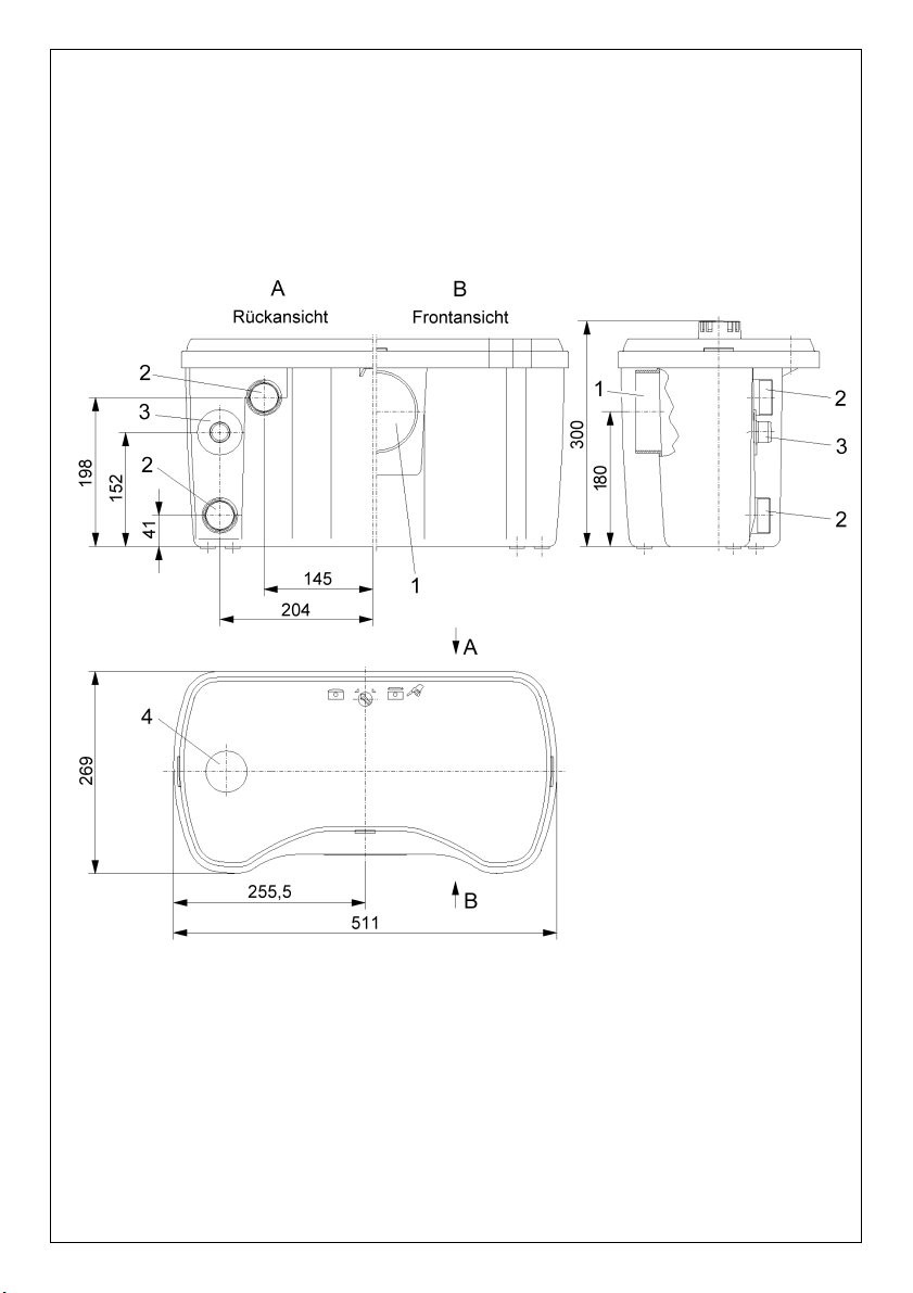
Fig. 1
Page 3
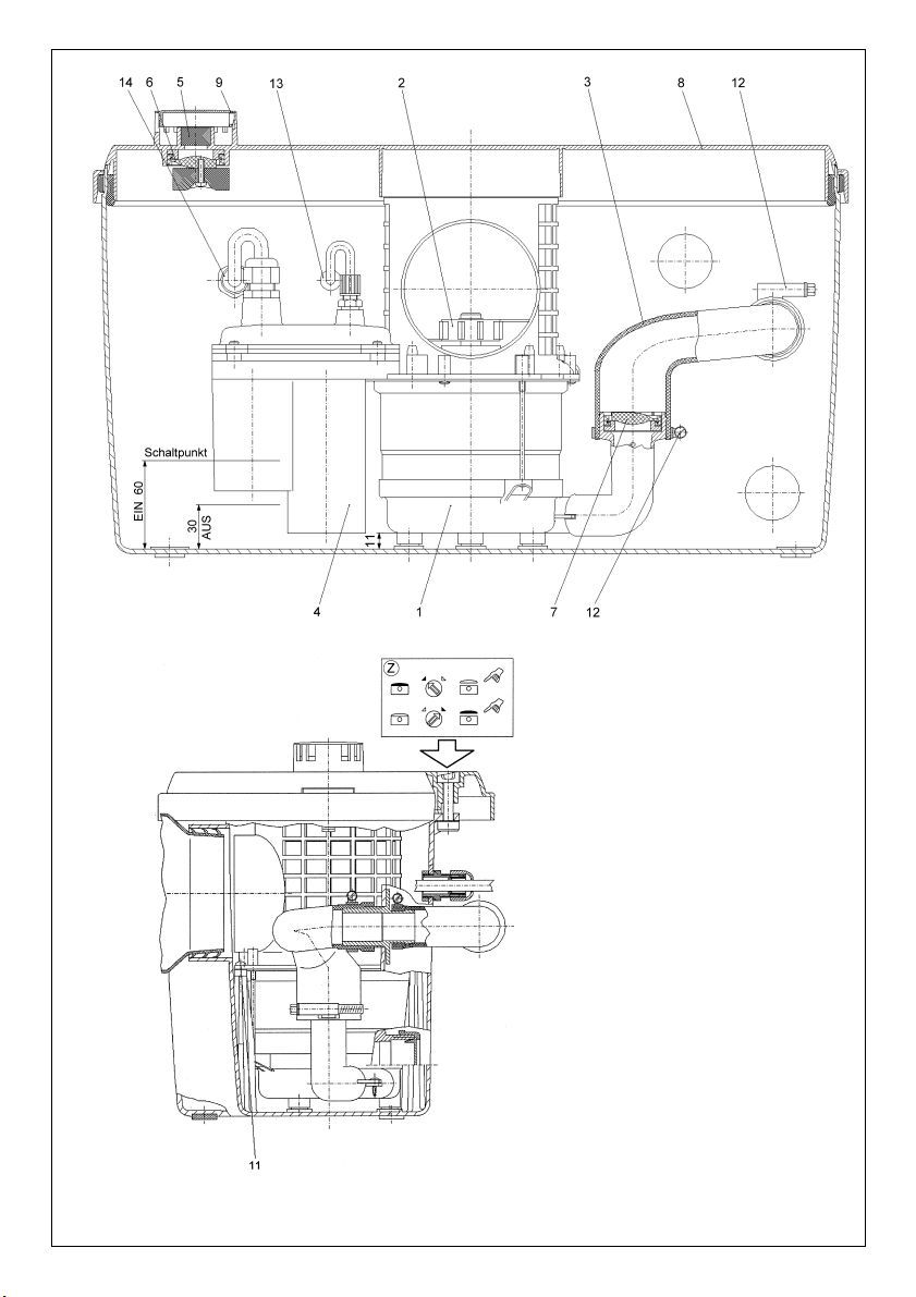
Fig. 2
Page 4
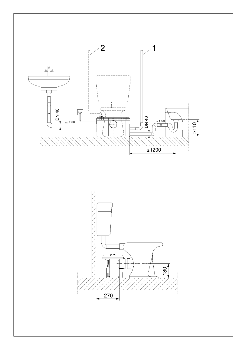
Fig. 3
Page 5
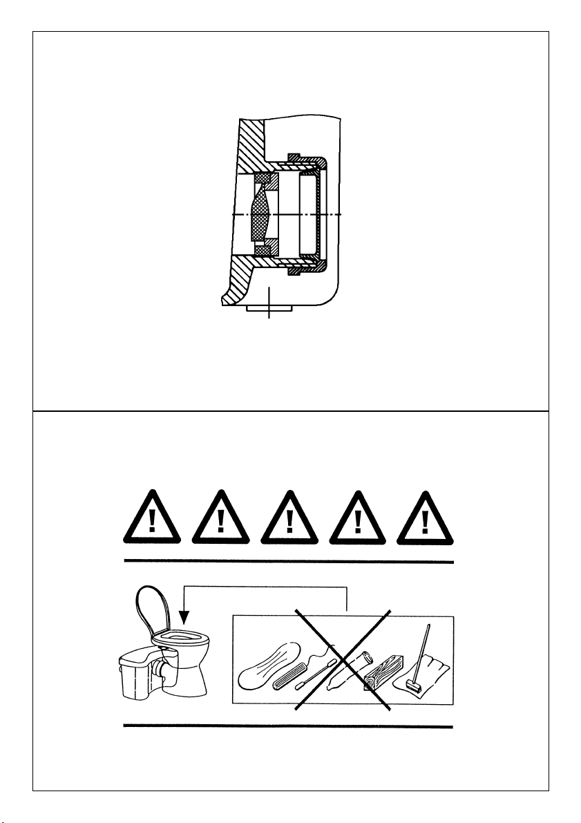
Fig. 5
Fig. 4
Page 6

D CE-Konformitäts-
erklärung
Hiermit erklären wir, daß dieses Aggregat folgenden einschlägigen Bestimmungen
entspricht:
EG-Maschinenrichtlinien
89/392/EWG i.d.F.,
91/368/EWG, 93/44/EWG,
93/68/EWG
Elektromagnetische
Verträglichkeit
89/336/EWG i.d.F.
92/31/EWG, 93/68/EWG
Angewendete harmonisierte
Normen, insbesondere
EN 809, EN 50 081-1,
EN 50 082-1, EN 50 081-2,
EN 50 082-2.
GB EC declaration of
conformity
We hereby declare that this
unit complies with the
following relevant provisions:
EC machinery directive
89/392/EWG in this version,
91/368/EWG, 93/44/EWG,
93/68/EWG
Resistance to
electromagnetism
89/336/EWG in this version
92/31/EWG, 93/68/EWG
Applied harmonized standards in particular:
EN 809, EN 50 081-1,
EN 50 082-1, EN 50 081-2,
EN 50 082-2.
F
Déclaration de
conformité CE
Par la présente, nous
déclarons que cet
agrégat sitisfait aux
dispositions suivantes:
Directives CEE relatives
aux machines 89/392/CEE,
91/368/CEE, 93/44/CEE,
93/68/CEE
Compatibilité
électromagnétique
89/336/CEE, 92/31/CEE,
93/68/CEE
Normes utilisées harmonisées, notamment
EN 809, EN 50 081-1,
EN 50 082-1, EN 50 081-2,
EN 50 082-2.
NL EG-verklaring van
overeenstemming
iermede verklaren wij dat
deze machine voldoet aan
de volgende bepalingen:
EG-richtlijnen betreffende
machines 89/392/EEG,
91/368/EEG, 93/44/EEG,
93/68/EEG
Elektromagnetische
tolerantie
89/336/EEG, 92/31/EEG,
93/68/EEG
Gebruikte geharmoniseerde
normen, in het bijzonder
EN 809, EN 50 081-1,
EN 50 082-1, EN 50 081-2,
EN 50 082-2.
E Declaración de
conformidad CE
Por la presente declaramos
que esta unidad satisface las
disposiciones pertinentes
siguientes:
Directivas CE sobre
máquinas 89/392/CEE,
91/368/CEE, 93/44/CEE,
93/68/CEE
Compatibilidad electromagnética 89/336/CEE,
92/31/CEE, 93/68/CEE
Normas armonizadas
utilizadas particularmente
EN 809, EN 50 081-1,
EN 50 082-1, EN 50 081-2,
EN 50 082-2.
I Dichiarazione di
conformità CE
Con la presente si dichiara
che le presenti pompe sono
conformi alle seguenti
direttive di armonizzazione
Direttiva Macchine CEE
89/392/CEE, 91/368/CEE,
93/44/CEE, 93/68/CEE
Compatibilità
elettromagnetica
89/336/CEE, 92/31/CEE,
93/68/CEE
Norme armonizzate applicate, in particolare
EN 809, EN 50 081-1,
EN 50 082-1, EN 50 081-2,
EN 50 082-2.
SF CE-standardinmukai-
suusseloste
Ilmoitamme täten, että tämä
laite vastaa seuraavia
asiaankuuluvia määräyksiä:
EY-konedirektiivit
89/392/ETY, 91/368/ETY,
93/44/ETY, 93/68/ETY
Sähkömagneettinen
soveltuvuus
89/336/ETY, 92/31/ETY,
93/68/ETY
Käytetyt yhteensovitetut
standardit, erityisesti
EN 809, EN 50 081-1,
EN 50 082-1, EN 50 081-2,
EN 50 082-2.
S EEC konformitets-
deklaration
Härmed förklaras att denna
maskin uppfyller följande
bestämmelser:
EEC maskindirektiv
89/392/EEC i denna version,
91/368/EEC, 93/44/EEC,
93/68/EEC
Elektromagnetisk kompatibilitet 89/336/EEC i denna
version, 92/31/EEC,
93/68/EEC
Tillämpade harmoniserade
normer, särskilt:
EN 809, EN 50 081-1,
EN 50 082-1, EN 50 081-2,
EN 50 082-2.
H EK. azonossági
nyilatkozat
Ezennel kijelentjük, hogy az
agregát a megkívánt alanti
feltételeknek
megfelel:
EK-Gépirányelvek
89/392/EWG, 91/368/EWG,
93/44/EWG, 93/68/EWG
Elektromagnetikus
ÖsszeegyeztethetŒség
89/336/EWG, 92/31/EWG,
93/68/EWG
Alkalmazott, harmonizált
normák, különösen az
EN 809, EN 50 081-1,
EN 50 082-1, EN 50 081-2,
EN 50 082-2.
Page 7

GR ∆ήλωση συµµρφωσης
µε τους κανονισµούς CE
∆ηλώνουµε τι το προϊν
αυτ ικανοποιεί τις
ακλουθες διατάξεις:
Οδηγίες CEE σχετικά
µε µηχανήµατα
89/392/CEE, 91/368/CEE,
93/44/CEE, 93/68/CEE
Ηλεκτροµαγνητική
συµβαττητα
89/336/CEE, 92/31/CEE,
93/68/CEE
Εναρµονισµένα
χρησιµοποιούµενα
πρτυπα, ιδιαίτερα
EN 809, EN 50 081-1,
EN 50 082-1, EN 50 081-2,
EN 50 082-2.
CZ Osvûdãení o shodnosti s
normami EU
Prohla‰ujeme tímto, Ïe toto
zafiízení odpovídá následujícím pfiíslu‰n˘m ustanovením:
Smûrnice o strojírenském
zafiízení ES 89/392/EHS
vãetnû dodatkÛ,
91/368/EHS, 93/44/EHS,
93/68/EHS
Elektromagneticá sná‰enlivost 89/336/EHS vãetnû
dodatkÛ, 92/31/EHS,
93/68/EHS
PouÏité souhlasné normy,
zejména:
EN 809, EN 50 081-1,
EN 50 082-1, EN 50 081-2,
EN 50 082-2.
PL OÊwiadczenie
zgodnoÊci EC
Niniejszym oÊwiadczamy, ˝e
pompa odpowiada nast´pujàcym w∏aÊciwym dla niej
dyrektywom:
Wytyczne dla przemys∏u
maszyncwego EC
89/392/EEC w tej wersji,
91/368/EEC, 94/44/EEC,
93/68/EEC
OdpornoÊç elektromagnetyczna EC 89/336/EEC
w tej wersji, 92/31/EEC,
93/68/EEC
Zastosowano normy zharmonizowane, w szczególnoÊci:
EN 809, EN 50 081-1,
EN 50 082-1, EN 50 081-2,
EN 50 082-2.
RUS Zaåvlenie o sootvetst-
vii normam, dejst-
vuœwim v Evropejs-
kom Soob-westve
Nastoåwim dokumentom
zaåvlåem, hto dannaå usta-
novka sootvetstvuet sle-
duœwim postanovleniåm:
Директивы EC относи-
тельно машин и станков
89/392/ЦЕЕ, 91/368/ЦЕЕ,
93/44/ЦЕЕ, 93/68/ЦЕЕ
Qlektromagnitnaå sov-
mestimostæ 89/336/CEE,
92/31/CEE, 93/68/CEE
Ispolæzovavπieså garmo-
nizirovannye standarty i
normy, v
hastnosti
EN 809, EN 50 081-1,
EN 50 082-1, EN 50 081-2,
EN 50 082-2.
DK EF-overensstemmels-
eserklæring
Det erklæres hermed, at
dette udstyr er i overensstemmelse med følgende
bestemmelser:
EU maskindirektiver:
89/392/EØF i denne
udgave, 91/368/EØF,
93/44/EØF, 93/68/EØF
Elektromagnetisk
kompatibilitet:
89/336/EØF i denne udgave, 92/31/EØF, 93/68/EØF
Anvendte harmoniserede
normer, især:
EN 809, EN 50 081-1,
EN 50 082-1, EN 50 081-2,
EN 50 082-2.
N EU-overensstemmelse-
serklæring
Det erklæres herved at dette
utstyret stemmer overens
med følgende bestemmelser:
EU-direktiver for maskiner
89/392/EEC og følgende,
91/368/EEC, 93/44/EEC,
93/68/EEC
Elektromagnetisk
kompatibilitet
89/336/EEC og følgende,
92/31/EEC, 93/68/EEC
Anvendte harmoniserte normer, i særdeleshet
EN 809, EN 50 081-1,
EN 50 082-1, EN 50 081-2,
EN 50 082-2.
TR Uygunluk Belgesi
As¸agˇí´daki cihazlarí´n takibi
standartlara
vygun oldugˇ unu temin
ederiz:
AB-Makina Standartlari
89/392/EWG i.d.F.,
91/368/EWG, 93/44/EWG,
93/68/EWG
Elektromanyetik
Uyumluluk
89/336/EWG i.d.F.,
92/31/EWG, 93/68/EWG
Özellikle kullaní´lan Normlar
EN 809, EN 50 081-1,
EN 50 082-1, EN 50 081-2,
EN 50 082-2.
2011678.3
WILO AG
Nortkirchenstraße 100
44263 Dortmund · Germany
Quality Management
Page 8

3
D
1. Allgemeines . . . . . . . . . . . . . . . . . . . . . . . . . 5
2. Sicherheit . . . . . . . . . . . . . . . . . . . . . . . . . . . 5
3. Transport und Zwischenlagerung. . . . . . . . . 6
4. Beschreibung des Erzeugnisses . . . . . . . . . 6
5. Aufstellung/Einbau. . . . . . . . . . . . . . . . . . . . 7
6. Inbetriebnahme . . . . . . . . . . . . . . . . . . . . . . 8
7. Wartung . . . . . . . . . . . . . . . . . . . . . . . . . . . . 8
8. Störungen, Ursachen und Beseitigung . . . . 9
GB
1. General Information . . . . . . . . . . . . . . . . . . . 10
2. Safety precautions . . . . . . . . . . . . . . . . . . . . 10
3. Transport and storage . . . . . . . . . . . . . . . . . 11
4. Description of product and accessories . . . 11
5. Assembly and installation . . . . . . . . . . . . . . 12
6. Starting up . . . . . . . . . . . . . . . . . . . . . . . . . . 13
7. Maintenance. . . . . . . . . . . . . . . . . . . . . . . . . 13
8. Faults, causes and remedies . . . . . . . . . . . . 14
F
1. Généralités . . . . . . . . . . . . . . . . . . . . . . . . . . 15
2. Sécurité . . . . . . . . . . . . . . . . . . . . . . . . . . . . 15
3. Transport et stockage
avant utilisation . . . . . . . . . . . . . . . . . . . . . . 16
4. Description du produit . . . . . . . . . . . . . . . . . 16
5. Installation / Montage . . . . . . . . . . . . . . . . . . 17
6. Mise en service . . . . . . . . . . . . . . . . . . . . . . 17
7. Entretien . . . . . . . . . . . . . . . . . . . . . . . . . . . . 17
8. Défauts, causes et remèdes . . . . . . . . . . . . 19
NL
1. Algemeen . . . . . . . . . . . . . . . . . . . . . . . . . . . 20
2. Veiligheid . . . . . . . . . . . . . . . . . . . . . . . . . . . 20
3. Transport en tussenopslag. . . . . . . . . . . . . . 21
4. Beschrijving van het product . . . . . . . . . . . 21
5. Opstelling/Montage . . . . . . . . . . . . . . . . . . . 22
6. Inwerkingstelling . . . . . . . . . . . . . . . . . . . . . 23
7. Onderhoud . . . . . . . . . . . . . . . . . . . . . . . . . . 23
8. Storingen, oorzaken en oplossingen . . . . . . 24
E
1. Generalidades . . . . . . . . . . . . . . . . . . . . . . . 25
2. Instrucciones de seguridad . . . . . . . . . . . . . 25
3. Transporte y almacenamiento . . . . . . . . . . . 26
4. Descripción del producto. . . . . . . . . . . . . . . 26
5. Colocación/Instalación. . . . . . . . . . . . . . . . . 27
6. Puesta en funcionamiento . . . . . . . . . . . . . . 28
7. Mantenimiento . . . . . . . . . . . . . . . . . . . . . . . 28
8. Fallos: causas y eliminación . . . . . . . . . . . . 29
I
1. Generalità . . . . . . . . . . . . . . . . . . . . . . . . . . . 30
2. Sicurezza . . . . . . . . . . . . . . . . . . . . . . . . . . . 30
3. Trasporto e magazzinaggio . . . . . . . . . . . . . 31
4. Descrizione del prodotto
e accessori. . . . . . . . . . . . . . . . . . . . . . . . . . 31
5. Montaggio/Installazione . . . . . . . . . . . . . . . 31
6. Messa in esercizio . . . . . . . . . . . . . . . . . . . . 32
7. Manutenzione. . . . . . . . . . . . . . . . . . . . . . . . 32
8. Blocchi, cause e rimedi. . . . . . . . . . . . . . . . 34
Page 9

ENGLISH
Information on operation
Dear customer,
In this chapter we would like to explain how the
ready-installed unit functions and operates.
However, we would also encourage you to read the
safety instructions described in the complete manual
for assembly and operation carefully.
Repairs on this unit should only be carried out by an
expert or by Wilo customer services.
The unit’s functions are all automatic. It is not neces-
sary to service the unit. Cleaning, if required, should
be carried out in accordance with the following instructions.
Cleaning
The unit cleans itself during regular use. Only seldomused units should be cleaned every three months
(also internally) as follows:
Pull the plug out of the socket. Pour a mild cleaning
agent into the toilet bowl and flush. After approximately 5 mins, plug the plug back in. Flush until the
pump switches on and pumps out the cistern. Then
flush again.
In the long term, the level of safety is increased when
the pump’s functioning and quiet running are checked
by a technical operator.
1. General Information
Installation and commissioning
by qualified personnel only!
1.1 Uses
An automatic mini lifting unit with cutting implement
for the sanitation of individual toilets, hand basins,
showers and bidets, whose dirty or waste water cannot
be transported into the canal system with a natural fall
and must therefore be lifted above the reflux level. The
additional draining points connected to the unit must
be located in the same room (limited use of mini lifting
unit). Another WC must be available above the reflux
level. This unit is particularly suitable for the sanitation
of toilets and showers in cellars.
The norm DIN EN 12050-3, DIN EN 12056 and
DIN 1986-100 should be adhered to when installing
the unit.
The lifting unit is not suitable for transporting solid
material such as hygiene articles, food leftovers,
long-fibred materials or solvents, fats and oil. It is
not permitted to connect the unit to a toilet with a
flushing valve.
1.2 Technical description
– Maximum transporting
capacity: 4 m
3
/h
– Maximum head: 5.7 m
– Max. flow medium
temperature: 35 °C
– Voltage/frequency: 1~230 V, 50 Hz
– Power input: 0.45 kW
– Speed: 2650
1
/min
– Nominal current: 2.1 A
– Type of operation: S3 28 %, 36 s
– Type of protection: IP 44
– Discharge connection: DN 25/32
– Inlet connection: DN 100 with seal collar
– Additional supply: 2 x DN 40 in
accordance with
DIN 1986 incl. blind
cover and collar
– Ventilation: 25 mm outer diameter
– Dimensions W x H x D: 511 x 300 x 269 mm
– Useful volume: 12 l
– Weight: 7.8 kg
When ordering spare parts, all details on the unit’s
rating plate should be given.
2. Safety precautions
These instructions contain important information
which must be followed when installing and operating the pump. It is therefore imperative that they be
read by both the installer and the operator before the
pump is installed or started up. Both the general
safety instructions in the ‘Safety precautions’ section
and those in subsequent sections indicated by danger
symbols should be carefully observed.
2.1 Danger symbols used in these
operating instructions
Safety precautions in these operating instructions
which, if not followed, could cause personal injury are
10
Page 10

ENGLISH
indicated by the symbol:
Safety precautions warning of danger due to electricity are indicated by the symbol:
Safety precautions which, if not followed, could
damage the pump or installation and cause it to malfunction are indicated by the word:
2.2 Qualified Personnel
The personnel installing the pump must be appropriately qualified to carry out this work.
2.3 Risks incurred by failure to comply
with the safety precautions
Failure to comply with the safety precautions could
result in personal injury or damage to the pump or
installation. Failure to comply with the safety precautions could also invalidate any claim for damages.
In particular, failure to comply with these safety precautions could give rise, for example, to the following
risks:
– the failure of important parts of the pump or installation,
– personal injury due to electrical and mechanical
causes,
– personal injury and damage to the environment due
to failure to comply with hygiene regulations when
handling sewage.
2.4 Safety precautions for the operator
Existing regulations for the prevention of accidents
must be followed.
To prevent the risk of electric shock or electrocution,
VDE regulations and those of the local supply company must be followed.
The warning stickers included in the delivery must be
attached in a visible position on the toilet cover (in
direct view of the toilet, if necessary).
2.5 Safety precautions for inspection
and installation
The operator must ensure that all inspection and
installation work is carried out by authorised and
qualified specialists who have carefully studied these
instructions. In principle, work on the unit may only
be carried out after it has been brought to a standstill.
2.6 Unauthorised alterations and manufacture
of spare parts
Alterations to the pump or installation may only be
carried out with the manufacturer’s consent. The use
of original spare parts and accessories authorised by
the manufacturer will ensure safety. The use of any
other parts may invalidate claims invoking the liability
of the manufacturer for any consequences.
2.7 Improper use
The operational safety of the unit supplied can only
be guaranteed if it is used in accordance with paragraph 1 of the operating instructions. Under no circumstances may the limits exceed or fall short of
those given in the catalogue or data sheet.
3. Transport and storage
– Care should be taken during transport that the unit
is not damaged by impact against other objects.
– The unit should be stored in a dry, frost-free place.
4. Description of the product
4.1 Description of the unit
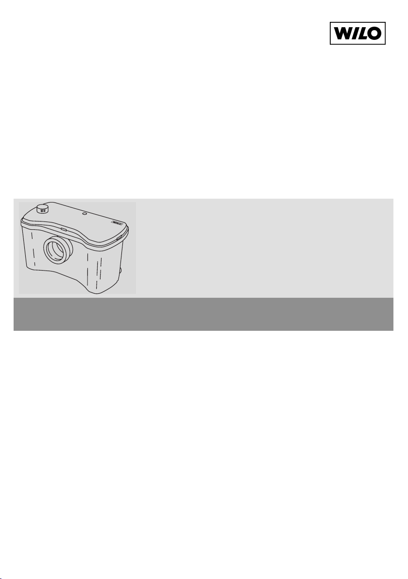
The automatic mini lifting unit (fig. 1) is a plastic gasproof and waterproof collector tank which is placed
directly behind a pedestal type toilet with a horizontal waste connection pipe (DIN EN 37).
The supply channel is sealed with a self-sealing collar
(see fig. 1, pos. 1).
The connections (fig. 1, pos. 2) for two additional
drainage points and also for the compressed air
piping (fig. 1, pos. 3) are located at the back of the
cistern. The space behind the unit makes it easy to
guide the pipes. In this way, the additional supply
channels and the compressed air piping can be
connected from both sides.
The pump which is built into the cistern (fig. 2, pos. 1)
is equipped with a cutting tool (fig. 2, pos. 2) which
lies above it and is easily accessible. The thick matter
is broken down enough that it can be transported
through the pump and compressed air piping (fig. 2,
pos. 3).
11
ATTENTION!
Page 11

ENGLISH
The motor coil is protected by an overload safety
device which automatically switches off the motor if
exposed to an above-average level of stress. After
the motor has cooled down, it is automatically
switched back on.
The in-built booster relay (fig. 2, pos. 4) switches the
unit on and off, depending on the level.
The activated carbon filter integrated into the unit
(fig. 2, pos. 5) enables airing and ventilation to take
place directly in the installation room or by means of
an aeration pipe on the roof which should be connected separately. In order to prevent the collection tank
from overflowing through the activated carbon filter in
the event of pump failure and an increase in the level
of liquid, an additional flap trap (fig. 2, pos. 6) has
been added. The drain connection also contains a
flap trap (fig. 2, pos. 7).
4.2 Products delivered
– mini lifting unit
– hose connection set
– 1 inlet checkvalue DN 40
– 2 welches for DN 40 (enclosed)
– warning sticker
– instructions for assembly and operation
5. Assembly/Installation
5.1 Assembly
– The unit should be installed in a frost-free room.
– The assembly area must be horizontal and flat.
– The lifting unit and the electrical connection (plug)
must remain accessible for maintenance even after
assembly.
– Remove covering cap (fig. 2, pos. 8) using the
tommy bar (fig. 2, pos. Z) and pressing the 3 spring
hooks (at side and front).
– The lifting unit is connected directly to the toilet
bowl with a horizontal waste connection pipe (in
accordance with DIN EN 37).
– The remaining drainage areas (e.g. wash basin,
bidet or shower) are connected to the additional
supply channels. The union nut, pressure ring and
existing angle collar should then be pushed over
the supply channel (outer-Ø 40 mm, commercially
available PVC pipe).
Push the PVC pipe into the supply channel connection pipe and screw the union nut tightly on to the
inlet connection pipe.
The unused inlet opening must be locked with the
cowl provided:
– Push the pressure ring on to the cowl
– Slide on the seal (cross section form: three-sided)
with the wide edge pointing to the pressure ring
– Lay the cowl in the union nut and screw on to the
supply channel opening.
The additional side supply channels
(DN 40) must be positioned above the
highest possible water lever (180 mm).
For this reason the construction level
(base) of the shower basin must lie
at least 180 mm higher than the
construction level of the mini lifting
unit (fig. 3). The shower surface may
be reduced to 110 mm above the
construction level when installing
Viega-domoplex discharge fittings,
when the distance between the lifting
unit and the shower is equal to or
larger than 1,200 mm.
– The flap trap (fig. 4) is pushed into the lower supply
channel opening as far as the limit stop in such a
way that the trap is open to the cistern. Then push
in the supply pipe as described above (use of trap
not permissible in Germany).
– Shorten the pressure hose to the desired length,
push it into the desired position on the hose
connection pieces and secure with the clamp.
– Push the conical end of the pressure hose as far as
possible onto the pressure pipeline (DN 25 or DN 32)
which should be connected on site and secure
against sliding with a clamp.
– It is recommended that a shut-off device be instal-
led in the pressure pipeline. It must be suitable for
waste water containing sewage and should be
connected on site.
– Connect pressure pipeline (fig. 3, pos. 1, minimum-
Ø DN 25) upwardly onto the collector pipe.
– If the pressure pipeline runs horizontally off centre, it
must be laid with a loop when it comes out of the unit.
– Press on covering cap.
– In order to protect against possible reflux out of the
public channel, the pressure pipeline should be
formed as a “pipe loop”. It must be placed over the
locally set reflux level (usually street level).
– If ventilation takes place through a vent connection
in the roof rather than through the activated carbon
filter which is integrated into the unit, the cap
12
ATTENTION!
Page 12

ENGLISH
(fig. 2, pos. 9) should be removed from the ventilation and the vent connection (fig. 3, pos. 2, innerØ 25 mm, commercially available PVC pipe) and
should be pushed by a flexible piece of hose on to
the support. The activated carbon filter (fig. 2, pos. 5)
can be removed.
– The warning sticker included in the delivery (fig. 5)
must be adhered in a visible position on the toilet
cover (if necessary, in direct view of the toilet).
5.2 Electrical installation
–Electrical work must be carried out by a
qualified and licensed electrician in strict
compliance with local regulations. If the
units power cable is damaged it must be
replaced by the customer service or a
similar qualified person.
– The mains current and voltage must comply with the
data on the rating plate of the unit to be connected.
– Earthing must be carried out according to regulations.
– Line side fuse protection: 10 A, neutral.
6. Starting up
– Plug in shock-proof plug
– Flush toilet twice during initial start-up
– Monitor all pipe connections for leakages. If neces-
sary, tighten hose clamps.
– Adjust the cistern so that the flushing volume does
not fall below 6 l of water.
7. Maintenance
The operation reliability is increased in the long run
when the perfect functioning and quiet running of the
pump are monitored.
The unit cleans itself when used regularly. Seldomused units should be cleaned internally now and
again as follows:
Pull out the plug. Pour a mild cleaning agent into the
toilet bowl and flush. After approximately 5 mins, plug
in the unit, flush, leave the unit to pump and then flush
again.
7.1 Maintenance and care of unit (fig. 2)
– Flush 2–3 times and pump the cistern empty
Pull out the plug before checking the
unit!
– Remove covering cap (fig. 2, pos. 8) using the
tommy bar (fig. 2, pos. Z) and pressing the 3 snap
hooks (side and front).
Danger of injury and infection from
cutting instruments! Use protective
gloves!
– If necessary, remove strainer basket and all foreign
bodies from the unit.
– Eliminate impurities on the cistern walls.
– Clean vent pipe or ventilating valve, renew acti-
vated carbon filter.
– Assemble in opposite order
– When using toilet freshners, make sure that they
are safely secured to the WC.
7.2 Dismantling the pump (fig. 2)
Flushing, opening the unit and observing warning
symbols as described in 7.1
– Unscrew the 3 fixing screws at the motor flange
(fig. 2, pos. 11).
– Unscrew the upper hose clamp (fig. 2, pos. 12) on
the discharge connection.
– Unscrew the screw of the ventilation pipe (fig. 2,
pos. 13) on the cistern wall and pull off the ventila-
tion pipe.
– Unscrew the connection cable PG screw joint
(fig. 2, pos. 14) on the tank wall and pull the cable
through to the inside of the cistern.
– If the pump is to be removed from the tank com-
pletely, screw off the electric plug and take the
cable out of the PG screw joint.
– Take out the pump with booster relay and electri-
cal connection.
– Clean the cutting instrument, impeller and the
opening of the booster relay.
– Assemble the components in the opposite order.
– Carry out test run.
For reasons of hygiene, used KH 32–0.4
units should be emptied and cleaned
before transportation. Furthermore, all
components which come into contact
with infectious material should be disinfected
(spray disinfected). The components must be
tightly sealed in sufficiently large, tear-resistant
plastic sacks and packed so that they do not leak.
They should be disposed of by reliable haulage
contractors immediately.
13
Page 13

ENGLISH
14
Fault Cause Remedy
Motor does not run Lack of voltage Check voltage and fuses
Cutting implement blocked, Dismantle cap, rotate motor shaft clockwise freely,
overload switch clean cutting implement. In the event of reoccurrence,
disengaged contact customer services.
motor overloaded, overload If the event of reoccurrence, contact customer
switch disengaged services.
booster relay defect contact customer services
motor defect contact customer services
motor runs, pump pressure pipeline blocked remove blocking or buckling
does not function or buckled carry out test run
unit ventilation blocked remove and clean ventilation pipe or replace activated
carbon filter
pump runs in short ventilation blocked clean ventilation
intervals
leak in flap trap clean or replace
cistern ventilation stops reproduce function
motor makes loud foreign bodies in unit Dismantle motor and clean. If necessary, contact
noises when rotating customer services.
8. Faults, causes and remedies
If the fault cannot be remedied, please contact your local plumbing and heating specialist or Wilo
customer services.
Subject to technical alterations!
Page 14

✍
Page 15

Page 16

 Loading...