

Wilo DrainLift Box 32/8DS, DrainLift Box 32/8, DrainLift Box 32/11D, DrainLift Box 40/10D, DrainLift Box 32/11DS Installation And Operating Instructions Manual
...Page 1
Pioneering for You
Wilo-DrainLift Box
en Installation and operating instructions
2521833 • Ed.05/2017-07
·
Page 2

Page 3

en
Table of contents
1 General information ................................................................................................................................................................. 5
1.1 About these instructions ..................................................................................................................................................................................5
1.2 Copyright ............................................................................................................................................................................................................5
1.3 Subject to change..............................................................................................................................................................................................5
1.4 Warranty..............................................................................................................................................................................................................5
2 Safety......................................................................................................................................................................................... 5
2.1 Identification of safety instructions................................................................................................................................................................5
2.2 Personnel qualifications....................................................................................................................................................................................7
2.3 Electrical work ....................................................................................................................................................................................................7
2.4 Monitoring devices ............................................................................................................................................................................................7
2.5 Transport.............................................................................................................................................................................................................7
2.6 Installing/dismantling........................................................................................................................................................................................7
2.7 During operation ................................................................................................................................................................................................8
2.8 Maintenance tasks.............................................................................................................................................................................................8
2.9 Operator responsibilities...................................................................................................................................................................................8
3 Application/use......................................................................................................................................................................... 8
3.1 Intended use.......................................................................................................................................................................................................8
3.2 Improper use.......................................................................................................................................................................................................8
4 Product description.................................................................................................................................................................. 9
4.1 Design..................................................................................................................................................................................................................9
4.2 Operating principle .........................................................................................................................................................................................10
4.3 Operating modes............................................................................................................................................................................................. 10
4.4 Operation with frequency converter............................................................................................................................................................ 11
4.5 Type key........................................................................................................................................................................................................... 11
4.6 Technical data .................................................................................................................................................................................................11
4.7 Scope of delivery............................................................................................................................................................................................. 11
4.8 Accessories ......................................................................................................................................................................................................11
5 Transportation and storage................................................................................................................................................... 12
5.1 Delivery............................................................................................................................................................................................................. 12
5.2 Transport.......................................................................................................................................................................................................... 12
5.3 Storage .............................................................................................................................................................................................................12
6 Installation and electrical connection .................................................................................................................................. 12
6.1 Personnel qualifications................................................................................................................................................................................. 12
6.2 Installation types............................................................................................................................................................................................. 13
6.3 Operator responsibilities................................................................................................................................................................................ 13
6.4 Installation .......................................................................................................................................................................................................13
6.5 Electrical connection...................................................................................................................................................................................... 18
7 Commissioning........................................................................................................................................................................ 19
7.1 Personnel qualifications................................................................................................................................................................................. 19
7.2 Operator responsibilities................................................................................................................................................................................ 19
7.3 Operation .........................................................................................................................................................................................................20
7.4 Application limits ............................................................................................................................................................................................20
7.5 Test run ............................................................................................................................................................................................................ 20
7.6 Adjusting the follow-up time ....................................................................................................................................................................... 21
8 Operation................................................................................................................................................................................. 21
9 Decommissioning/dismantling.............................................................................................................................................. 21
9.1 Personnel qualifications................................................................................................................................................................................. 21
9.2 Operator responsibilities................................................................................................................................................................................ 21
9.3 Decommissioning............................................................................................................................................................................................ 21
10 Maintenance and repair.......................................................................................................................................................... 22
10.1 Personnel qualifications................................................................................................................................................................................. 22
10.2 Removing pumps for maintenance purposes .............................................................................................................................................22
Installation and operating instructions Wilo-DrainLift Box 3
Page 4

en
11 Faults, causes and remedies .................................................................................................................................................. 23
12 Spare parts............................................................................................................................................................................... 24
13 Disposal.................................................................................................................................................................................... 24
13.1 Protective clothing .........................................................................................................................................................................................24
13.2 Information on the collection of used electrical and electronic products.............................................................................................. 24
4 WILO SE 2017-07
Page 5

1 General information
General information en
1.1 About these instructions
1.2 Copyright
1.3 Subject to change
1.4 Warranty
These installation and operating instructions are an integral part of the product. Read
these instructions before commencing work and keep them in an accessible place at all
times. Strict adherence to these instructions is a requirement for intended use and correctly operating the product. All specifications and markings on the product must be
observed.
The language of the original operating instructions is German. All other languages of
these instructions are translations of the original operating instructions.
These installation and operating instructions have been copyrighted by the manufacturer. The contents, of whatever type, may not be reproduced or distributed, or used for
purposes of competition and shared with others.
The manufacturer reserves the right to make technical modifications to the product or
individual components. The illustrations used may differ from the original and are intended as an example representation of the product.
The specifications in the current “General Terms and Conditions” apply to the warranty
and the warranty period. These can be found at www.wilo.com/legal
Any deviations must be contractually agreed and shall then be given priority.
Claim to warranty
If the following points are complied with, the manufacturer is obligated to rectify every
qualitative or constructive flaw:
▪The defects are reported in writing to the manufacturer within the warranty period.
▪Application according to intended use.
▪All monitoring devices are connected and tested before commissioning.
2 Safety
Exclusion of liability
Exclusion from liability excludes all liability for personal injury, material damage or fin-
ancial losses. This exclusion ensues as soon as one of the following applies:
▪Inadequate configuration due to inadequate or incorrect instructions by the operator or
the client
▪Non-compliance with installation and operating instructions
▪Improper use
▪Incorrect storage or transport
▪Incorrect installation or dismantling
▪Insufficient maintenance
▪Unauthorised repairs
▪Inadequate construction site
▪Chemical, electrical or electro-chemical influences
▪Wear
This chapter contains basic information which must be adhered to during the individual
phases of the life cycle. Failure to follow the installation and operating instructions will
result in injuries to persons, damage to the environment and the device and result in the
loss of any claims for damages. Failure to follow the instructions can result in the fol-
lowing risks:
▪Injury to persons from electrical, mechanical and bacteriological factors as well as elec-
tromagnetic fields
▪Environmental damage from leakage of hazardous substances
▪Property damage
▪Failure of important functions of the product
Additionally, the instructions and safety instructions in the other chapters must be
observed!
2.1 Identification of safety instructions
Installation and operating instructions Wilo-DrainLift Box 5
These installation and operating instructions set out safety instructions for preventing
personal injury and damage to property. These safety instructions are shown differently:
▪Safety instructions relating to personal injury start with a signal word, are preceded by
a corresponding symbol and are shaded in grey.
Page 6
en Safety
DANGER
Type and source of the danger!
Consequences of the danger and instructions for avoidance.
▪Safety instructions relating to property damage start with a signal word and are dis-
played without a symbol.
CAUTION
Type and source of the danger!
Consequences or information.
Signal words
▪DANGER!
Failure to observe the safety instructions will result in serious injuries or death!
▪WARNING!
Failure to follow the instructions can lead to (serious) injuries!
▪CAUTION!
Failure to follow the instructions can lead to property damage and a possible total loss.
▪NOTICE!
Useful information on handling the product
Symbols
These instructions use the following symbols:
Danger of electric voltage
Danger of explosion
Personal protective equipment: Wear a safety helmet
Personal protective equipment: Wear foot protection
Personal protective equipment: Wear hand protection
Personal protective equipment: Wear safety goggles
Personal protective equipment: Wear mouth protection
Transport by two persons
Useful information
Markups
‡ Prerequisite
1. Work step/list
⇒ Notice/instructions
▶ Result
6 WILO SE 2017-07
Page 7

Safety en
2.2 Personnel qualifications
2.3 Electrical work
Personnel must:
▪Be instructed in the locally applicable accident prevention regulations.
▪Have read and understood the installation and operating instructions.
Personnel must have the following qualifications:
▪Electrical work: Electrical work must be carried out by a qualified electrician (in accord-
ance with EN50110-1).
▪Installation-/dismantling: The technician must be trained in the use of the necessary
tools and fixation materials for the relevant construction site. The technician must also
be trained in the processing of plastic pipes. In addition, the technician must be instruc-
ted in the locally applicable guidelines for sewage lifting units.
Definition of “qualified electrician”
A qualified electrician is a person with appropriate technical education, knowledge and
experience who can identify and prevent electrical hazards.
▪A qualified electrician must carry out the electrical work.
▪When connecting to the mains, comply with the locally applicable laws and regulations
of the local energy supply company.
▪Before commencing work, disconnect the device from the mains and secure it against
being switched on again without authorisation.
▪Personnel are trained on the execution of the electrical connection and the options for
switching off the device.
▪Comply with the technical specifications contained in these installation and operating
instructions and on the rating plate.
▪Earth the device.
▪Switchgears are to be arranged overflow-proof.
▪Replace defective power supply cables immediately. Contact customer service.
2.4 Monitoring devices
2.5 Transport
The following monitoring devices must be provided on-site:
Circuit breaker
The size of the circuit breakers conforms to the rated current of the pump. The switch-
ing characteristics should comply with group B or C. Observe local regulations.
Residual-current device (RCD)
Comply with the regulations of the local energy supply company! The use of a residual-
current device is recommended.
If persons come into contact with the device and conductive fluids, secure the connec-
tion with a residual-current device (RCD).
▪Wear the following protective equipment:
– Safety shoes
– Safety helmet (when using lifting equipment)
▪Hold the reservoir when transporting the device. Never pull the power supply cable!
▪Devices weighing 50kg and over must be transported by two persons. Generally, it is
recommended that two persons transport the device.
▪If lifting equipment is used, observe the following points:
– Only use legally specified and approved lifting gear.
– Select the lifting gear based on the existing conditions (weather, attachment point,
load, etc.).
– Always attach the lifting gear to the attachment points.
– The stability of the lifting equipment must be ensured during operation.
– When using lifting equipment, a second person must be present to coordinate the
procedure if required (e.g. if the operator’s field of vision is blocked).
– Persons are not permitted to stand beneath suspended loads. Do not carry suspen-
ded loads over workplaces where people are present.
2.6 Installing/dismantling
▪Wear the following protective equipment:
– Safety shoes
– Safety gloves against cuts
– Safety helmet (when using lifting equipment)
▪Locally applicable laws and regulations for work safety and accident prevention must be
complied with.
▪Disconnect the device from the mains and secure it against being switched on again
without authorisation.
▪Close the gate valve in the inlet and in the pressure pipe.
▪Provide adequate aeration in closed rooms.
Installation and operating instructions Wilo-DrainLift Box 7
Page 8

en Application/use
▪When working in chambers and closed spaces, a second person must be present for
safety reasons.
▪Take immediate countermeasures if there is a build-up of toxic or suffocating gases!
▪Clean the device thoroughly both inside and outside.
2.7 During operation
2.8 Maintenance tasks
2.9 Operator responsibilities
▪Do not open the device!
▪Open all gate valves in the inlet and in the pressure pipe!
▪Ensure ventilation!
▪The operator is trained in the functionality and the options for switching off the device!
▪Wear the following protective equipment:
– Closed safety goggles
– Safety gloves
▪Close the gate valve in the inlet.
▪Only carry out maintenance tasks mentioned in these installation and operating in-
structions.
▪Only original parts from the manufacturer may be used for maintenance and repairs.
Use of parts other than the original parts releases the manufacturer from any liability.
▪Collect any leakage of pumped fluid immediately and dispose of it according to the loc-
ally applicable guidelines.
▪Installation and operating instructions must be in a language which the personnel can
understand.
▪Make sure that the personnel is relevantly trained for the specified work.
▪Provide the necessary protective equipment and make sure that the personnel wears it.
▪Safety and information signs mounted on the device must be always legible.
▪Train the personnel pertaining to the functioning of the system.
▪Eliminate risk from electrical current.
Children and persons younger than 16years or with reduced physical, sensory or mental
capacities or limited experience are prohibited from handling the product! A technician
must supervise persons younger than 18years!
3 Application/use
3.1 Intended use
▪For the backflow resistant drainage of discharge points for buildings below the back-
flow level
▪Installation inside buildings (according to EN12056 und DIN1986‑100)
▪Pumping sewage without faeces (according to EN12050-2) out of the domestic area
A grease trap must be installed for pumping greasy sewage!
Application limits
Improper use and overstraining will cause overflow through the floor drain. The follow-
ing application limits must be observed:
▪Max. intake/h:
– DrainLift Box 32/8: 1300l
– DrainLift Box 32/11: 1200l
– DrainLift Box 40/10: 870l
– DrainLift Box 32/8D: 2400l
– DrainLift Box 32/11D: 2200l
– DrainLift Box 40/10D: 1620l
– DrainLift Box 32/8DS: 3000l
– DrainLift Box 32/11DS: 3100l
– DrainLift Box 40/10DS: 1740l
▪Max. pressure in the pressure pipe: 1.7bar
▪Max. ground water pressure: 0.4bar (4mWs above the floor of the tank)
▪Fluid temperature:
– DrainLift Box 32...: 3...35°C, max. fluid temperature for 3mins: 60°C
– DrainLift Box 40...: 3...40°C
▪Ambient temperature: 3...40°C
8 WILO SE 2017-07
Page 9
3.2 Improper use
4
3
1
2
3
Product description en
DANGER
Explosion due to pumping of explosive fluids!
Pumping of highly flammable and explosive fluids (gasoline, kerosene, etc.) in pure
form is strictly prohibited. There is a risk of fatal injury due to explosion! The lifting
unit is not designed for these fluids.
The following fluids must not be introduced:
▪Sewage containing faeces (in accordance with EN12050-1)
▪Sewage from drainage objects that are located above the backflow level and can be
drained by natural fall (in accordance with EN12056-1).
▪Debris, ash, garbage, glass, sand, plaster, cement, lime, mortar, fibrous materials, tex-
tiles, paper towels, wet-wipes (e.g. fleece cloths, moist toilet paper wipes), nappies,
cardboard, coarse paper, synthetic resins, tar, kitchen waste, grease, oil
▪Slaughterhouse waste, disposal of slaughtered animals and animal waste (liquid ma-
nure, etc.)
▪Toxic, aggressive and corrosive media, such as heavy metals, biocides, pesticides, acids,
bases, salts, swimming-pool water (in Germany in accordance with DIN1986-3)
▪Cleaning agents, disinfectants, dishwashing or laundry detergents in excess amounts,
and such which have a high degree of foam formation
▪Drinking water
Intended use also includes compliance with this manual. Any other use is regarded as
non-compliant with the intended use.
4 Product description
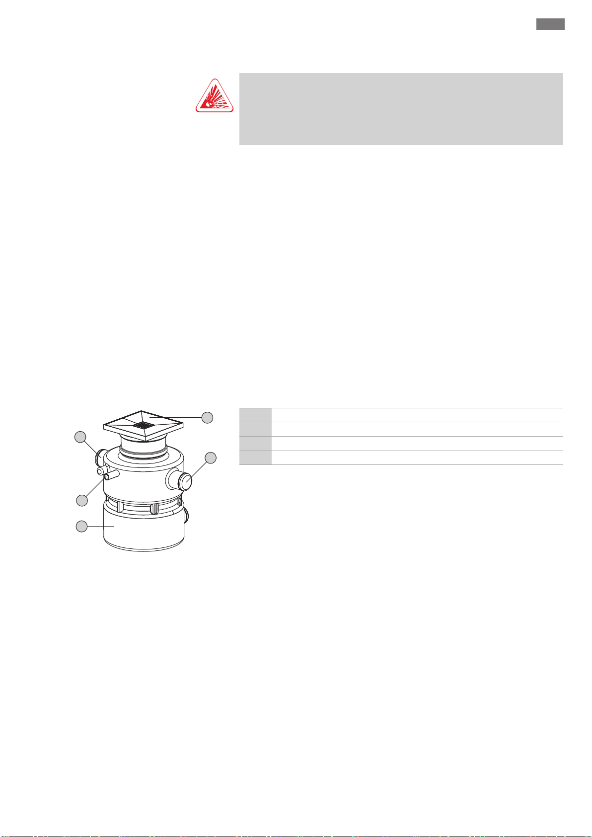
4.1 Design
Fig.1: Overview
4.1.1 Collection reservoir
4.1.2 Pumps used
Ready for connection and fully-automatic sewage lifting unit for concealed floor installation within buildings.
1 Tank
2 Pressure connection
3 Inlet und ventilation connection
4 Height-adjustable cover with floor drain
Gas-tight and watertight collection reservoir made from plastic, with deposit-free interior. The two inlet connections DN100 are offset by 180°. The free inlet connection is
used to ventilate the power supply cables and route them outside. The pressure connection is positioned to the side of the inlet connections. For easy maintenance of the
unit, the collection reservoir is equipped with an inspection opening in the cover.
Depending on its type, the sewage lifting unit is equipped with the following submers-
ible sewage pumps:
▪Box 32/8: TMW 32/8
▪Box 32/11: TMW 32/11
▪Box 32/11HD: TMW 32/11HD
▪Box 40/10: TC 40/10
The submersible pumps are pre-installed in the collection reservoir, including pipework
and non-return valve.
Drain TMW 32
Submersible sewage pump in single-phase current version with sheath current cooling
and built-in thermal overload protection with automatic reactivation. The seal is cre-
ated on the fluid side with a mechanical seal, and on the motor side with a rotary shaft
Installation and operating instructions Wilo-DrainLift Box 9
Page 10

en Product description
seal. During operation, the standard-equipped twister function ensures continuous turbulence in the suction area of the pump, preventing settling sediments from sinking
and settling. This ensures a clean pump sump and reduces the build-up of odours.
In the HD version, the motor housing and shaft are made from high-quality stainless
steel (1.4404).
Drain TC 40
Submersible sewage pump in single-phase current version with oil-filled motor and
built-in thermal overload protection with automatic reactivation. The seal is created on
the fluid side with a mechanical seal, and on the motor side with a rotary shaft seal.
4.1.3 Level control
4.1.4 Switchgear
4.2 Operating principle
Level control is carried out using a float switch. In the version without a switchgear, the
float switch of the submersible sewage pump is used. The “pump On/Off” switching
level is pre-set by the cable length of the attached float switch.
In the version with a switchgear, a separate float switch is installed in the tank. The
“pump on” switching point is determined by the length of the float switch’s cable. The
switching point for “pump off” is defined by the set follow-up time in the switchgear.
Additionally, a further float switch can be installed for a high water alarm.
In the “DS” version, a switchgear is supplied. The switchgear is preconfigured and undertakes control of both submersible sewage pumps. The switchgear can also be used
to implement a collective fault signal (SSM). For further information on the switchgear,
consult the attached installation and operating instructions.
Single-pump system: Wilo-DrainLift Box...
The sewage that arrives is channelled into the collection reservoir via the inlet pipe,
where it collects. When the water level reaches the switch-on level, the pump is
switched on by the attached float switch and the collected sewage is pumped into the
connected pressure pipe. When the switch-off level is reached, the pump is immediately deactivated.
Double-pump system: Wilo-DrainLift Box... D (main/standby pump)
The sewage that arrives is channelled into the collection reservoir via the inlet pipe,
where it collects. When the water level reaches the switch-on level, the pump is
switched on by the attached float switch and the collected sewage is pumped into the
connected pressure pipe. When the switch-off level is reached, the pump is immediately deactivated.
If the main pump malfunctions, pumping is performed by the standby pump.
4.3 Operating modes
Double-pump system: Wilo-DrainLift Box... DS (alternating operation)
The sewage that arrives is channelled into the collection reservoir via the inlet pipe,
where it collects. When the water level reaches the switch-on level, the pump is
switched on by a float switch and the collected sewage is pumped into the connected
pressure pipe. When the switch-off level is reached, the pump is deactivated after the
set follow-up time. Pump cycling is carried out after every pumping procedure. If one
pump malfunctions, the other pump is automatically activated.
For enhanced operational reliability, a further float switch can be installed in the tank. A
high water level can be defined using this float switch. When the high water level is
reached:
▪The switchgear emits audible and visual alarm signals.
▪Both pumps undergo forced switch-on.
▪The collective fault signal is activated.
As soon as the water drops below the high water level, the standby pump is switched
off once the follow-up time has elapsed, and the warning message is acknowledged
automatically. The main pump continues to run in the regular pumping cycle.
Operating mode S3: Intermittent periodic duty
This operating mode defines a switching cycle in a combination of periods of operation
and standstill. Specified value (e.g. S325%) relates to the operating time. The switch-
ing cycle has a duration of 10min.
If two values (e.g. S325%/120s) are specified, the first value relates to the operating
time. The second value specifies the max. period of the switching cycle.
10 WILO SE 2017-07
Page 11

Product description en
The unit is not designed for continuous duty! The max. volume flow applies to intermittent periodic duty according to EN60034-1!
4.4 Operation with frequency converter
4.5 Type key
4.6 Technical data
Type Box 32/8 Box
Mains connection
Power consumption [P1]
Rated power [P2]
Max. delivery head
Max. volume flow
Activation type
Operating mode
Fluid temperature
Max. fluid temperature for
1~230V/50Hz 1~230V/50Hz 1~230V/50Hz
450W 750W 940W
370W 550W 600W
7m 7m 7m 10m 10m 10m 10.5m 10.5m 10.5m
8.5m³/h 8m³/h 8m³/h 11.5m³/h 11m³/h 11m³/h 14.5m³/h 13.5m³/h 13.5m³/h
direct direct direct
S3 25% S3 25% S3 50% S3 25% S3 25% S3 50% S3 25% S3 25% S3 50%
3...35°C 3...35°C 3...40°C
60°C 60°C -
3mins
Ambient temperature
Free ball passage
Gross volume
Switching volume
Cable length to plug
Cable length to
3...40°C 3...40°C 3...40°C
10mm 10mm 24mm
113l 113l 113l
26l 24l 30l 24l 22l 31l 29l 27l 29l
10m 10m 1.5m 10m 10m 1.5m 5m 5m 1.5m
- - 10m - - 10m - - 5m
switchgear
Plug
Pressure connection
Inlet connection
Ventilation connection
Weight
Shockproof plug Shockproof plug Shockproof plug
40mm 40mm 40mm
DN100 DN100 DN100
DN100 DN100 DN100
26kg 31kg 36kg 28kg 35kg 40kg 33kg 45kg 50kg
32/8D
Operation on the frequency converter is not permitted.
Example: DrainLift Box 32/8 DS
Box
32
8
Sewage lifting unit for sewage not containing faeces
Nominal diameter of pressure connection in mm
Max. delivery head in m
Version of the sewage lifting unit:
D
without = single-pump system
D = double-pump system
Control:
S
without = float switch fitted
S = switchgear
Overview of technical data for the various versions.
Box
32/8DS
Box 32/11 Box
32/11D
Box
32/11DS
Box 40/10 Box
40/10D
Box
40/10DS
4.7 Scope of delivery
▪Sewage lifting unit with complete pipework, non-return valve and pre-installed pump
▪“DS” version incl. switchgear
▪Container cover with tile frame and floor drain
▪Shell cover
▪O-ring to seal shell cover and as anti-syphon trap
▪Pressure hose (inside diameter: 40mm) including hose clips
▪Installation and operating instructions
4.8 Accessories
▪Collar to seal the installation against ground water entering the building.
If watertight concrete (white tub) is sealed, install a collar!
▪Alarm switchgears
▪“DS” retrofit kit: Switchgear, float switch and fixation material (only for “D” version)
Installation and operating instructions Wilo-DrainLift Box 11
Page 12

en Transportation and storage
5 Transportation and storage
5.1 Delivery
5.2 Transport
After receiving the shipment, this must be checked immediately for defects (damage,
completeness). Defects must be noted on the freight documentation! Furthermore, defects must be notified to the transport company or the manufacturer immediately on
the day of receipt of shipment. Subsequently notified defects can no longer be asserted.
WARNING
Head and foot injuries due to a lack of protective equipment!
Danger of (serious) injuries during work. Wear the following protective equipment:
• Safety shoes
• Safety helmet must be worn if lifting equipment are used!
▪To transport the device, hold the tank – never pull the power supply cable!
▪Devices weighing 50kg and over must be transported by two persons. It is generally re-
commended that two persons transport the device.
▪If lifting equipment is used, observe the following points:
– Use legally specified and approved lifting gear.
– Select the lifting gear based on the existing conditions (weather, attachment point,
load, etc.).
– Always attach the lifting gear to the attachment points (handle or lifting eyelet).
– The stability of the lifting equipment must be ensured during operation.
– When using lifting equipment, a second person must be present to coordinate the
procedure if required (e.g. if the operator’s field of vision is blocked).
– Persons are not permitted to stand beneath suspended loads. Do not carry suspen-
ded loads over workplaces where people are present.
5.3 Storage
CAUTION
Total damage due to moisture ingress
Moisture ingress in the power supply cable damages the power supply cable and the
pump! Never immerse the end of the power supply cable in a fluid and firmly seal it
during storage.
▪Place the lifting unit on a firm bearing surface and secure it against slipping and falling
over!
▪The max. storage temperature is -15°C...+60°C at a max. humidity of 90%, non-con-
densing. Frost-proof storage at a temperature of 5...25°C with relative humidity of
40...50% is recommended.
▪Drain the collection reservoir completely.
▪Coil the power supply cables and attach them to the pump.
▪Seal the ends of the power supply cables against water ingress.
▪Remove the existing switchgear and store it according to the manufacturer’s instruc-
tions.
▪Tightly seal all open connections. Attach the chamber cover and close the floor drain.
▪Do not store the lifting unit in rooms in which welding work is carried out. The resulting
gases or radiation can corrode the elastomer parts.
▪Protect the lifting unit from direct sunlight and heat. Extreme heat can damage the
reservoir and the built-in pumps!
▪Elastomer parts are subject to natural brittleness. Contact customer service if the pump
must be stored for more than 6months.
6 Installation and electrical con-
nection
6.1 Personnel qualifications
12 WILO SE 2017-07
▪Electrical work: Electrical work must be carried out by a qualified electrician (in accord-
ance with EN50110-1).
▪Installation-/dismantling: The technician must be trained in the use of the necessary
tools and fixation materials for the relevant construction site. The technician must also
Page 13

Installation and electrical connection en
be trained in the processing of plastic pipes. In addition, the technician must be instructed in the locally applicable guidelines for sewage lifting units.
6.2 Installation types
6.3 Operator responsibilities
6.4 Installation
▪Concealed floor installation in buildings
The following installation types are not permitted:
▪Floor-mounted installation
▪Outside buildings
▪Observe locally applicable accident prevention and safety regulations of trade associ-
ations.
▪Provide protective equipment and ensure that the protective equipment is worn by
personnel.
▪Observe all regulations for working under suspended loads when using lifting equip-
ment.
▪The operating space must be freely accessible in order to be able to easily deliver the
lifting unit incl. transport equipment. There must be adequate access to the operating
space, and existing elevators must have the required load-bearing capacity.
▪Carry out installation according to locally applicable regulations (DIN1986-100,
EN12056).
▪For correct installation and operation of the lifting unit, lay and prepare the pipes ac-
cording to the consulting documents.
▪Mains connection must be arranged overflow-proof.
WARNING
Hand and foot injuries due to lack of protective equipment!
Danger of (serious) injuries during work. Wear the following protective equipment:
• Safety gloves
• Safety shoes
6.4.1 Note on pipework
CAUTION
Material damage due to incorrect transport!
It is not possible to transport and to position the lifting unit alone. There is a risk of
material damage to the lifting unit! Always transport the lifting unit and align it at
the installation location with two persons.
▪Prepare the operating space/installation location:
– Clean, free of coarse solids
– Dry well
– Frost-free
– Well lit
▪Ensure adequate aeration of the operating space.
▪Ensure a clearance of min. 60cm around the floor drain for maintenance work.
▪Provide drawing wire in pipework for the installation of power supply cables.
▪Lay the power supply cable in accordance with regulations. There must be no danger to
the power supply cables (i.e. tripping, damage during operation). Check the cable cross-
section and cable-length to ensure the power supply cables are suitable for the install-
ation type.
▪The mounted switchgear (“DS version”) is not overflow-proof. Install the switchgear
sufficiently high. Ensure good operation!
▪To transport the lifting unit, take hold of the inlet connecting piece – never pull the
power supply cable! The unit must be transported by two persons.
The pipework is subjected to different pressures during operation. Pressure surges can
also occur (e.g. when closing the non-return valve) which may be several times higher
than the pump pressure, depending on the operating conditions. These different pres-
sures put a strain on the piping and the pipe adaptors. In order to ensure safe and fault-
less operation, the following parameters must be checked and adapted for the piping
and pipe adaptors and designed according to the requirements:
▪Pressure resistance of pipework and pipe adaptors
▪Tensile strength of the pipe adaptors (= longitudinal force fit connection)
The following points must also be observed:
Installation and operating instructions Wilo-DrainLift Box 13
Page 14

en Installation and electrical connection
Box: 500
Box...D/DS: 470
455
800
760...880
1
2
3
4
5
8 9
6
7
▪Pipes are self-supporting.
▪Connect the pipes free of stress and vibrations.
▪No tensile or compressive forces must act on the lifting unit.
▪In order to allow the inlet pipe to drain automatically, lay the pipe with a slope to the
lifting unit.
▪Do not install constrictions/reductions!
▪Provide a gate valve in the inlet and the pressure pipe on-site!
6.4.2 Work steps
6.4.3 Preparatory tasks
6.4.4 Excavating the pit
Fig.2: Excavating the pit
The lifting unit is installed in the following steps:
▪Preparatory tasks.
▪Excavate the pit.
▪Prepare the lifting unit for installation.
▪Install the lifting unit.
Lay the power supply cables, connect the piping, backfill the pit.
▪Install the cover and restore the sub-floor.
▪Final tasks.
▪Unpack the lifting unit and remove the securing mechanisms.
▪Check the scope of delivery.
▪Check all components are in proper working condition.
CAUTION!Do not install defective components! Defective components can lead to
system failures!
▪Place accessories to one side and keep them for later use.
▪Select the installation location.
CAUTION!Do not install the lifting unit in peaty ground! Peaty ground can result in
the destruction of the tank!
1 Ground
2 Underlay
3 Levelling layer
4 Filling material
5 Concrete layer
6 Screed
7 Tiled floor
8 Ventilation/cable duct
9 Pressure pipe
‡ Preparatory tasks completed.
1. Excavate the pit, taking into account the following points:
⇒ Pump chamber height
⇒ Position of the connections
⇒ Underlay approx. 200mm
⇒ Levelling layer approx. 100mm
⇒ Max. height adjustment of the cover.
2. Install the load-bearing mineral mixture underlay properly and seal it (Dpr 97%).
3. Add a levelling layer of sand and level off.
4. Prepare the piping provided by the customer.
6.4.5 Preparing the lifting unit for installation
Prior to installation of the lifting unit, complete the following tasks:
▪Check the position of the pumps.
▪Check the level control.
14 WILO SE 2017-07
▪Open the connection port.
▪Install accessories:
– Mini float switch
An additional mini float switch must be installed for the high water alarm.
– Collar
NOTICE!If watertight concrete (white tub) is sealed, an additional collar (available
as an accessory) must be installed on the neck of the tank!
Page 15

Installation and electrical connection en
DrainLift Box 32...D DrainLift Box 40...D
DrainLift Box 32...DS DrainLift Box 40...DS
190 mm
190 mm
Checking the position of the pumps
The pumps are mounted and positioned in the factory. The pumps may shift during
transport, which would impair proper function of the float switches. For this reason,
check that the pumps are in the correct position before installation, and if necessary
correct according to the illustrations.
Fig.3: Position of the pumps, without switchgear
Fig.4: Position of the pumps, with switchgear
Check the setting of the level control device
CAUTION
Incorrect alignment of the float switches may lead to malfunction!
For proper functioning, the float switches must have sufficient space to float and lie
flat on the surface of the water. Therefore, ensure correct alignment of the pumps
and floaters!
The level control device is factory-mounted and factory-set. The level control device
may shift from its mounting during transport and lead to malfunction of the lifting unit.
Therefore, check the fixation and the cable length of the float switches prior to installation and adjust if necessary.
▪Single- and double-pump system without switchgear
Level measurement is conducted by the pump’s attached float switch. The float switch
cable is fixed to the pump’s cable terminal. The length of the cable defines the switching level. NOTICE!For the Wilo-DrainLift Box 40... always affix the float switch cable
to the lower cable terminal!
Fig.5: Fixing and setting the float switches,
without switchgear
Installation and operating instructions Wilo-DrainLift Box 15
Page 16

en Installation and electrical connection
190 mm
1
2
2
4
3
6
3
5
6
min.
15 mm
1
2
3
4
5
▪Double-pump system with switchgear
Float switch for level control
1
Attached float switch, fixed in the “ON” position
2
Float switch holder
3
Float switch cable attachment point
4
Discharge pipe
5
Float switch holder attachment
6
The level is recorded by a separate float switch. The float switch is attached to the float
switch holder, while the float switch cable is fixed to the cross brace of the float switch
holder. The pump’s attached float switch must be fixed in the “ON” position:
Fig.6: Fixing and setting the float switches,
with switchgear
▪Wilo-DrainLift Box 32/... DS:The float switch is fixed to the pump’s cable terminal.
The float switch holder is fixed on the pipework!
▪Wilo-DrainLift Box 40/... DS:The float switch is attached to the float switch holder.
The float switch holder is fixed towards the centre of the tank!
NOTICE!For the float switch to work properly, the floater must float towards the
centre of the tank. Make sure that the float switch holder is aligned correctly!
Opening a connection port
Open the following connection ports:
▪Inlet: DN100
▪Ventilation: DN100
1. Approx. 15mm from the outside, open the port up with a saw.
2. Deburr the connection port.
▶ The connection port is now open.
Fig.7: Preparing the connections
Fig.8: High water level detection
Installing a mini float switch for high water alarm (only for “DS” version)
An additional mini float switch must be installed for the high water alarm to function.
The mini float switch is available as an accessory.
1 Float switch holder
2 Float switch for level control
3 Mini float switch for high water alarm
4 Discharge pipe
5 Float switch cable attachment
‡ Preparatory tasks completed.
‡ Pumps’ position set.
‡ Level control set.
1. Loosen the nut from the threaded bush. Keep approx. 5mm distance between the
nut and the end of the threaded bush.
2. Insert the threaded bush into the slotted hole on the float switch holder.
3. Retighten the nut to affix the mini float switch to the float switch holder.
4. Fix the float switch cable to the discharge pipe with a cable tie.
▶ The mini float switch is now installed.
Installing the collar
If watertight concrete is used (white tub), a collar must be fixed to the neck of the tank
to create a seal between the concrete and the tank. The collar is available as an accessory.
16 WILO SE 2017-07
Page 17

2
2 1
3
Fig.9: Installing the collar
1
2
3
4
5
6.4.6 Installing the lifting unit
Fig.10: Setting up the lifting unit
Installation and electrical connection en
1 Collar
2 Sealing bead
3 Clamp
‡ The neck of the tank must be clean and dry.
‡ The collar must not be damaged.
‡ Observe the manufacturer’s instructions!
1. Place the first clamp over the neck of the tank.
2. Fit the collar onto the neck of the tank, and place it between the two sealing
beads.
⇒ Use a lubricant to make installation easier!
3. Introduce the first clamp into the lower groove of the collar and tighten.
4. Place the second clamp over the neck of the tank and introduce it into the upper
groove of the collar.
5. Tighten the second clamp.
▶ The collar is now installed.
1 Ground
2 Underlay
3 Levelling layer
4 Filling material
5 Mains connection, version without switchgear
‡ Lifting unit prepared for installation.
‡ Two persons present.
‡ Installation materials required:
2x KG-bushing for DN100 connection ports.
1x hose section with 2x pipe clamp (included in scope of delivery).
1x anti-syphon trap for cable bushing
Filling material: Sand/gravel without sharp edges, grain size 0‑32mm
1. Place KG-bushing on the inlet pipe and the ventilation/cable duct.
2. Lift the lifting unit with the DN100 connecting pieces and lower it into the pit.
3. Align the connection ports with the pipes.
4. Bed the lifting unit into the levelling layer.
5. Bundle the power supply cables together and attach them to the discharge pipe
with a cable tie.
NOTICE!To enable the pumps or float switches to be lifted out of the tank as
required, a cable loop (approx.1m) must remain in the chamber!
CAUTION!The power supply cables must not impede the movement of the float
switch! If the float switch cannot move freely, this may cause the system to
malfunction.
6. All power supply cables (for pumps and float switches) should be led outside via
the ventilation pipe using a drawing wire.
NOTICE!Install an anti-syphon trap at the transition in the operating space!
7. Slide the KG-bushing over the DN100 connecting pieces to make the inlet and
ventilation connections.
8. Place the hose section on the pressure connection.
9. Fit the first pipe clamp and affix the hose section to the pressure connection. CAU-
TION!Max. tightening torque: 5Nm!
10.Attach the second pipe clamp.
11.Place the hose section on the discharge pipe and affix the hose section to the dis-
charge pipe using the second pipe clamp. CAUTION!Max. tightening torque:
5Nm!
NOTICE!To prevent a backflow from the main public sewer, the pressure pipe
must be installed as a “pipe loop”. The bottom edge of the pipe loop must be
Installation and operating instructions Wilo-DrainLift Box 17
Page 18

en Installation and electrical connection
1
2
3
4
5
6
3
1
2 2
above the locally defined backflow level (usually street level) at its highest
point!
12.Perform a leak test in accordance with the applicable regulations.
13.Fill the pit a layer at a time (layer thickness max.200mm) with filling material all
the way around to an even height, up to the bottom of the sealing bead and compact properly (Dpr. 97%).
While filling, ensure that the lifting unit remains vertical and stable and watch out
for deformation of the tank. Compact by hand directly by the tank wall (shovel,
hand rammer).
▶ The lifting unit is now installed properly.
6.4.7 Installing the cover and restoring
the sub-floor
1 Filling material
2 Tank cover with tile frame
3 O-Ring in the upper sealing bead
4 Concrete layer
5 Screed layer
6 Ceramic tiling
‡ Lifting unit installed.
Fig.11: Installing the tank cover
‡ Pit filled with filling material.
‡ Collar installed (mandatory when watertight concrete used!)
1. Insert the O-Ring in the upper sealing bead in the neck of the tank.
2. Apply a lubricant to the O-Ring.
3. Take the floor drain out of the tile frame.
4. Insert tank cover with tile frame into the neck of the tank.
5. Align the tile frame with the upper surface of the tiles in the operating space and
fix the tank cover in place.
CAUTION!Ensure the O-ring is in the correct position!
6. Restore the sub-floor: Fill in the concrete and screed layer.
NOTICE!After the concrete and screed have hardened, fill in any hollow spaces
with suitable material!
7. Restore the tile flooring.
▶ The lifting unit is now completely installed.
6.4.8 Final tasks
NOTICE
Only affix floor drain following function test!
The floor drain is fixed into the tile frame with silicone. If the floor drain is removed
after the silicone has set, the old silicone must be removed completely and the floor
drain re-installed.
1 Tile frame
2 Line of silicone
3 Floor drain
‡ Tiling work complete.
‡ Function test carried out.
1. Apply a line of silicone around the tile frame.
2. Allow the silicone to dry briefly (max. 5mins).
Fig.12: Installing the floor drain
18 WILO SE 2017-07
3. Insert the floor drain into the tile frame and lightly press it in.
4. Wait 24hours before walking on the floor drain.
▶ The floor drain is now installed.
Page 19

6.5 Electrical connection
6.5.1 Fuse on mains side
Commissioning en
DANGER
Risk of death due to electrocution!
Improper conduct when carrying out electrical work can lead to death due to electric
shock! Electrical work must be carried out by a qualified electrician in accordance
with the locally applicable regulations.
▪The mains connection must match the specifications on the rating plate.
▪Lay the power supply cables in accordance with the locally applicable regulations.
▪Arrange the socket for the mains connection so that it is overflow-proof.
For the “DS” version with switchgear, observe the following additional points:
▪Connect the power supply cables for pumps and level control devices according to the
wire assignments on the switchgear.
▪Earth the device properly in accordance with applicable local regulations.
The cross-section of the cable for the protective earth conductor connection must
comply with local regulations.
▪Attached switchgear is to be arranged overflow-proof.
Circuit breaker
The size of the circuit breakers conforms to the rated current of the pump. The switching characteristics should comply with group B or C. Observe local regulations.
6.5.2 Mains connection
6.5.3 “DS” version with switchgear
Residual-current device (RCD)
Comply with the regulations of the local energy supply company! The use of a residualcurrent device is recommended.
If persons come into contact with the device and conductive fluids, secure the connection with a residual-current device (RCD).
Wilo-DrainLift Box.../Wilo-DrainLift Box... D
The lifting unit’s pumps are equipped with shockproof plugs. For the connection to the
mains supply, one or two shockproof sockets (according to applicable local regulations)
must be provided by the customer.
Wilo-DrainLift Box... DS
The switchgear is equipped with a shockproof plug. For the connection to the mains
supply, a shockproof socket (according to applicable local regulations) must be
provided by the customer.
The “DS” version is equipped with a switchgear. The switchgear is pre-set in the factory
and features the following functions:
▪Level-dependent control
▪Motor protection
▪High water alarm
After installing the lifting unit, connect the pumps and level control device to the
switchgear. For the connection to the switchgear and for all further information on spe-
cific functions, consult the switchgear’s installation and operating instructions.
6.5.4 Operation with frequency converter
Operation on the frequency converter is not permitted.
7 Commissioning
7.1 Personnel qualifications
7.2 Operator responsibilities
Installation and operating instructions Wilo-DrainLift Box 19
▪Electrical work: Electrical work must be carried out by a qualified electrician (in accord-
ance with EN50110-1).
▪Operation/control: Operating personnel must be instructed in the functioning of the
complete system.
▪Providing installation and operating instructions by the lifting unit or at a place specially
reserved for it.
Page 20

en Commissioning
▪Making the installation and operating instructions available in the language of the per-
sonnel.
▪Making sure that the installation and operating instructions are read and understood by
all personnel.
▪All safety devices and emergency cut-outs must be active and checked to ensure that
they function properly.
▪The lifting unit is suitable for use under the specified operating conditions.
7.3 Operation
Wilo-DrainLift Box.../Box... D
The individual pumps are directly controlled by the attached float switch. After the plug
has been inserted in the socket, the respective pump is now ready for operation in
automatic mode.
Wilo-DrainLift Box... DS
CAUTION
Malfunction due to incorrect operation of the switchgear!
When the plug is inserted, the switchgear starts in the last operating mode that was
set. In order to be familiar with the operation of the switchgear, the installation and
operating instructions of the switchgear must be read before inserting the plug.
7.4 Application limits
7.5 Test run
The lifting unit is operated by the switchgear. The switchgear is preconfigured for use
with the lifting unit. For information on the operation of the switchgear and its individual displays, consult the installation and operating instructions for the switchgear.
Improper use and overstraining will cause overflow through the floor drain. The following application limits must be observed:
▪Max. intake/h:
– DrainLift Box 32/8: 1300l
– DrainLift Box 32/11: 1200l
– DrainLift Box 40/10: 870l
– DrainLift Box 32/8D: 2400l
– DrainLift Box 32/11D: 2200l
– DrainLift Box 40/10D: 1620l
– DrainLift Box 32/8DS: 3000l
– DrainLift Box 32/11DS: 3100l
– DrainLift Box 40/10DS: 1740l
▪Max. pressure in the pressure pipe: 1.7bar
▪Max. ground water pressure: 0.4bar (4mWs above the floor of the tank)
▪Fluid temperature:
– DrainLift Box 32...: 3...35°C, max. fluid temperature for 3mins: 60°C
– DrainLift Box 40...: 3...40°C
▪Ambient temperature: 3...40°C
Before the lifting unit starts in automatic mode, conduct a test run. A test run checks
the proper functioning of the unit.
‡ Lifting unit installed.
‡ Floor drain not installed.
1. Activate the lifting unit: Insert plug into socket.
⇒ Wilo-DrainLift Box.../Box... D:Lifting unit is in automatic mode.
⇒ Wilo-DrainLift Box... DS: Check operating mode of the switchgear.The
switchgear must operate in automatic mode.
2. Open the shut-off device on the inlet and pressure sides.
⇒ Collection reservoir is filled slowly.
3. Lifting unit is switched on and off using the level control.
⇒ To conduct a test run, complete two entire pumping procedures.
⇒ When pumping out, the pump must not start slurping operation.
Wilo-DrainLift Box.../Box... D: If slurping operation lasts longer than 1s, readjust the length of the float switch cable.
20 WILO SE 2017-07
Page 21

Operation en
Wilo-DrainLift Box... DS:If slurping operation lasts longer than 1s, adjust the
switchgear’s follow-up time.
4. Close the gate valve in the inlet.
⇒ The lifting unit should no longer switch on because no more fluid flows in. If
the lifting unit switches on again, the non-return valve is leaky. Contact customer service!
5. Open the gate valve in the inlet again.
▶ Lifting unit operates in automatic mode.
Following a successful test run, the floor drain must be installed in the tile frame!
7.6 Adjusting the follow-up time
8 Operation
9 Decommissioning/dismantling
9.1 Personnel qualifications
The pump run-time is set at the factory. If longer slurping noises can be heard (>1s) at
the end of the pumping process, reduce the follow-up time on the switchgear. For setting the follow-up time, observe the installation and operating instructions for the fitted switchgear!
NOTICE!If the follow-up time is adjusted, observe the operating mode of the lifting
unit. The operating mode specifies the max. permissible operating period!
The lifting unit operates in automatic mode by default and is switched on and off using
the integrated level control device.
‡ Commissioning was carried out.
‡ Test run has been completed successfully.
‡ The operation and functioning of the lifting unit are known.
1. Activate the lifting unit: Insert plug into socket.
2. “DS” version: Select automatic mode on the switchgear.
▶ The lifting unit operates in automatic mode and is controlled depending on level.
▪Operation/control: Operating personnel must be instructed in the functioning of the
complete system.
▪Installation-/dismantling: The technician must be trained in the use of the necessary
tools and fixation materials for the relevant construction site. The technician must also
be trained in the processing of plastic pipes. In addition, the technician must be instructed in the locally applicable guidelines for sewage lifting units.
▪Electrical work: Electrical work must be carried out by a qualified electrician (in accord-
ance with EN50110-1).
9.2 Operator responsibilities
9.3 Decommissioning
▪Observe locally applicable accident prevention and safety regulations of trade associ-
ations.
▪Provide the necessary protective equipment and make sure that the personnel wears it.
▪Ensure enclosed spaces have sufficient ventilation.
▪Take immediate countermeasures if there is a build-up of toxic or suffocating gases!
▪When working in enclosed spaces, a second person must be present for safety reasons.
WARNING
Warning: danger of infection!
Bacteria can form in sewage which can lead to infections. Wear the following protective equipment while performing the work:
• Closed safety goggles
• Breathing mask
• Protective gloves
When decommissioning the lifting unit, the lifting unit is switched off, but can be re-
activated at any time.
‡ Floor drain removed.
Installation and operating instructions Wilo-DrainLift Box 21
Page 22

en Maintenance and repair
‡ Protective equipment put on.
‡ DANGER!Risk of limbs being crushed or severed! Depending on the version of
the lifting unit, the pump’s float switch may need to be operated by hand to
manually force the unit to pump out. To do this, carefully reach into the tank
from above and activate the float switch. Never reach into the suction port. The
impeller can crush or sever limbs!
1. Close the gate valve in the inlet pipe.
2. Drain the collection reservoir.
Wilo-DrainLift Box.../Box... D: Turn the pump’s float switch upward. As soon as the
fluid has been pumped out, release the float switch.
Wilo-DrainLift Box... DS:Activate the lifting unit in manual mode.
3. Thoroughly hose down pumps, float switches and the tank with a hose through the
tank opening.
4. Drain the collection reservoir. Repeat steps 3 and 4 as required according to the
pollution degree.
5. Wilo-DrainLift Box... DS:Switch the switchgear to standby mode.
6. Switch the lifting unit off.
Pull the plug out of the socket. CAUTION!Secure the lifting unit against unex-
pected reactivation! Operating the unit without fluid can lead to irreparable
damage!
7. Close the gate valve in the pressure pipe.
8. Reinstall the floor drain and seal it with silicone (see “Final tasks”).
▶ The lifting unit is now out of operation.
10 Maintenance and repair
10.1 Personnel qualifications
WARNING
Warning: danger of infection!
Bacteria can form in sewage which can lead to infections. Wear the following protective equipment while performing the work:
• Closed safety goggles
• Breathing mask
• Protective gloves
For reasons of safety, and thus to guarantee correct function of the lifting unit, it must
always be maintained and repaired by professional service providers (e.g. customer service). The maintenance intervals for lifting units must be carried out in accordance with
EN12056‑4:
▪¼ year in the case of commercial companies
▪½ year for multi-family houses
▪1 year for single-family houses
A log must be kept of all maintenance and repair work. The service provider and oper-
ator must sign the log.
▪Electrical work: Electrical work must be carried out by a qualified electrician (in accord-
ance with EN50110-1).
▪Maintenance tasks: The technician must be familiar with the lifting unit. The technician
must also meet the requirements of EN12056 (including the individual parts).
10.2 Removing pumps for maintenance
purposes
22 WILO SE 2017-07
To carry out maintenance on the pumps easily, lift the pumps out of the tank.
Page 23

Faults, causes and remedies en
1
2
3
1 Discharge pipe to the pump
2 Discharge pipe in the tank
3 Discharge pipe, screwed connection
‡ Lifting unit taken out of operation.
‡ Floor drain removed.
‡ Protective equipment put on.
1. Reach into the tank from above.
2. Loosen the screwed connection.
3. Lift the pump out of the tank by the discharge pipe.
CAUTION!Risk of damage to the power supply cable! Lift the pump out of the
tank slowly and be careful of the power supply cable. If the power supply cable
is too short, do not lift the pump out of the tank. Damaging the power supply
cable can lead to irreparable damage!
Fig.13: Removing the pumps
11 Faults, causes and remedies
Fault
The pump does not pump properly
Volume flow too low
Current consumption too high
Delivery head too small
Pump does not run quietly/emits loud
Cause and remedy
5, 6, 7, 8, 9, 10, 11, 12, 16, 17, 18
1, 3, 7, 9, 12, 13, 14
1, 4, 5, 8, 14
1, 3, 5, 7, 9, 12, 13, 14, 17
1, 3, 10, 13, 14, 15, 17
noises
1. Inlet or impeller clogged
⇒ Remove deposits from the inlet, reservoir and/or pump → customer service.
2. Wear of inner parts (e.g. impeller, bearing)
⇒ Replace worn parts → customer service
3. Operating voltage too low
⇒ Have the mains connection checked → electrician
4. Float switch blocked
⇒ Check mobility of the float switch
5. Motor does not start because there is no voltage
⇒ Check the electrical connection → electrician
6. Inlet blocked
⇒ Clean the inlet
7. Motor winding or electric cable defective
⇒ Have the motor and electrical connection checked → electrician
8. Non-return valve clogged
⇒ Clean non-return valve → customer service
9. Water level dropped too low in the tank
⇒ Check level control and replace → customer service
10.Defective level control signal transmitter
⇒ Check signal transmitter and replace if necessary → customer service
11.Slide valve in the pressure pipe is not open or not sufficiently open
⇒ Fully open the slide valve
Installation and operating instructions Wilo-DrainLift Box 23
Page 24

en Spare parts
12.Impermissible amount of air or gas in fluid
⇒ customer service
13.Radial bearing in the motor defective
⇒ customer service
14.System-related vibrations
⇒ Check elastic connections of the piping ⇒ notify customer service if necessary
15.Winding temperature monitoring switched off due to excessive winding temperature
⇒ The motor switches back on automatically after the winding has cooled down.
⇒ Frequent switch-off by winding temperature monitoring → customer service
16.Pump ventilation clogged
⇒ Clean the pump ventilation line → customer service
17.Fluid temperature too high
⇒ Allow the fluid to cool
12 Spare parts
13 Disposal
13.1 Protective clothing
13.2 Information on the collection of
used electrical and electronic
products
Spare parts are ordered via customer service. To avoid return queries and incorrect orders, the serial or article number must always be supplied. Subject to change without
prior notice!
Used protective clothing must be disposed of in accordance with the locally applicable
guidelines.
Proper disposal and appropriate recycling of this product prevents damage to the environment and danger to your personal health.
NOTICE
Disposal in domestic waste is forbidden!
In the European Union, this symbol can appear on the product, the packaging or the
accompanying documentation. It means that the electrical and electronic products
in question must not be disposed of along with domestic waste.
To ensure proper handling, recycling and disposal of the used products in question,
please note the following points:
▪Only hand over these products at designated, certified collecting points.
▪Observe the locally applicable regulations!
Please consult your local municipality, the nearest waste disposal site, or the dealer who
sold the product to you for information on proper disposal. Further recycling informa-
tion can be found at www.wilo-recycling.com.
24 WILO SE 2017-07
Page 25

Page 26

Page 27

Page 28

Pioneering for You
WILO SE
Nortkirchenstr. 100
44263 Dortmund
Germany
T +49 (0)231 4102-0
T +49 (0)231 4102-7363
wilo@wilo.com
www.wilo.com
 Loading...