

Page 1
FIND OUT MORE
CAUTION: DO NOT con-
nect this brewer to hot
water. The inlet valve is
not rated for hot water.
CAUTION: Please use
this setup procedure
before attempting to use
this brewer. Failure to follow the
instructions can result in injury or
the voiding of the warranty.
C
WARNING
HOT LIQUID,
Scalding may occur.
Avoid splashing.
Important Safeguards/Conventions
FOR THE LATEST SPECIFICATIONS AND INFORMATION GO TO WWW.WILBURCURTIS.COM
should be performed by an authorized Wilbur Curtis service center.
Do NOT immerse the unit in water or any other liquid
• To reduce the risk of fi re or electric shock, do NOT open top or rear panel. No user serviceable parts
inside. Repair should be performed only by authorized service personnel.
•
Keep hands and other items away from hot parts of unit during operation.
Never clean with scouring powders, bleach or harsh implements.
WARNINGS – To help avoid personal injury Important Notes/Cautions
Sanitation Requirements
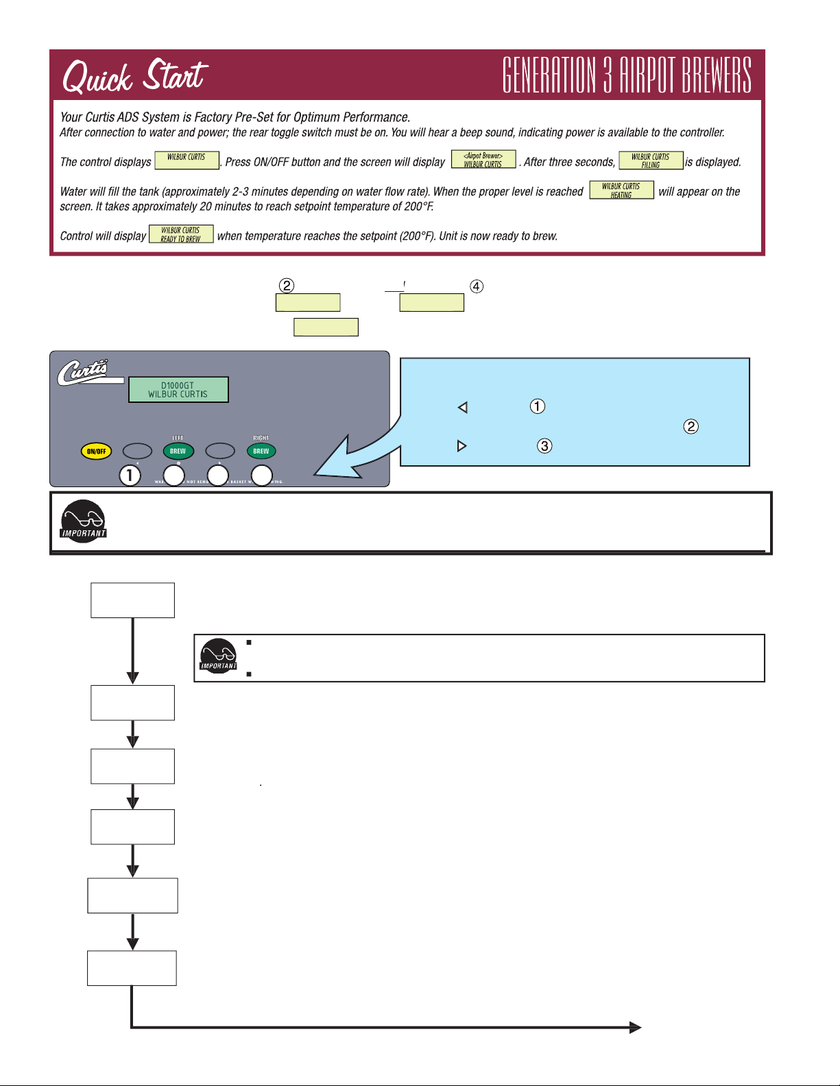
Curtis GT Units are Factory Pre-Set and Ready to Go… Right out of the Carton.
Following are the Factory Settings for your D1000GT Airpot Coffee Brewing System:
•
Brew Temperature = 200°F
•
Brew Volume = Set to dispensing vessel requirements (2.2 liters)
slight adjustments to meet your brewing needs, programming instructions are provided later in this manual.
System Requirements:
• Water Source 20 – 90 PSI (Minimum Flow Rate of 1 GPM)
• Electrical: See attached schematic for standard model or visit www.wilburcurtis.com for your model.
Equipment to be installed to comply with applicable federal, state, or local plumbing/electrical codes having
jurisdiction.
from the water fi lter to the brewer. NOTE: Some type of water fi ltration device must be used to maintain a
trouble-free operation. (In areas with extremely hard water, we suggest that a sedimentary and taste & odor
fi lter be installed.) This will prolong the life of your brewing system and enhance coffee quality.
provide a minimum of 1.0 GPM.
2. Connect the unit to an appropriate electrical power circuit.
3. Turn on the toggle (STANDBY/ON) switch behind the unit. The heating tank will start to fi ll. When the water
level in the tank rises to the correct volume, the heating elements will energize automatically.
With GT brewers, there is no danger of element burnout caused by an empty tank.
4. The heating tank will require 20 to 30 minutes to reach operating temperature (200°F). This will be indicated
when the screen reads READY TO BREW .
5. Prior to brewing, dispense 12 ounces of hot water through the hot water faucet.
The National Sanitation Foundation requires the following water connection:
can be moved for cleaning underneath.
2. In some areas an approved backfl ow prevention device may be required between the brewer and
water supply.
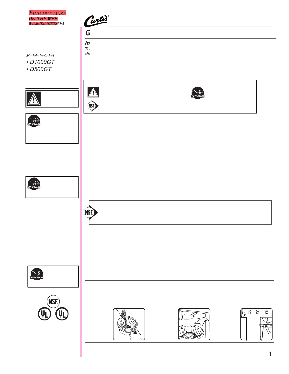
BREWING INSTRUCTIONS
2. Open lid on an empty airpot and place on deck, ready to receive coffee.
3. Place a new fi lter in brewcone.
4.Pour ground
coffee into
brewcone.
Brew
button.
5. Position
brewcone
into brew
rails.
WILBUR CURTIS COMPANY
Models Included
To avoid temperature
drop when first brewing
coffee into the airpot,
preheat the airpot with hot water.
Page 2
Brew Volume (Factory set to 2.2 Liters)
Selecting Brew by Volume or Brew by Time depends on whether you know your brew time before starting.
From Program Menus press > display will now show the next feature.
Brew by Volume: Press
to Select, display will now show Select Button. Select desired Brew button. To Begin... Press the
BREW button then hot water starts running, when correct volume is reached press BREW button again to stop the flow. Now
the volume has been set. Pressing > button will display the subsequent menu features.
Next item in the sequence is Brew by Time. Press
to Select, display will now show Select Button. The current time is now
shown. By pressing < > you can toggle back and forth from minutes to seconds to exit (ex). Change the time or set and exit
by pressing
Temperature (Factory set to 200°F)
Press
to Select. Press < > to move to desired temperature and then
to set. Temperature is programmable from 170ºF
to 204ºF in 2-degree increments.
Energy Save Mode (Factory set to OFF)
Press
to Select, < , >, ON, OFF or ON 140ºF ,
to set. When in ON, unit will automatically shut off 4 hours from last
brew. When feature is OFF, unit does not have the energy saving mode.
In the ON 140ºF position, temperature goes down to 140ºF. if unit has not brewed in 4 hours. This feature will save energy by
not heating the tank during periods of non-operation.
Brew Count Odom.
Press
to display total brew cycles. Press ex or Reset
hold
BREW button (green) and then press and release ON/OFF button.
respond to the buttons (see illustration below).
ENTER CODE
– – – –
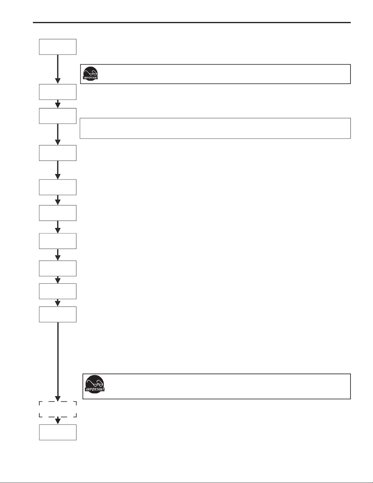
PROGRAM MENUS
< SELECT >
ENTERING PROGRAM
MODE
3
Temperature
Brew By Time
Brew By Volume
Program Menus
Energy Save Mode
Brew Count Odom
Continued, Page 3
PROGRAM MENUS
On D1000GT ONLY, brew buttons are independently programmable for Brew Volume (Volume or Time), Pre-infusion or Pulse
Brew.
Once volume is set and during actual brew cycle a 2 minute drip mode is added to total brew time.
All programming selections are performed with the three center buttons.
The symbols below the buttons are:
Scroll LEFT
SELECTION or ENTER to save new parameter
Scroll RIGHT
Model Select - D500GT ONLY. Always perform this fi rst. This feature re-sets all settings to the factory defaults.
Page 3
Pre-Infusion (Factory set to OFF)
Press
to Select. Display will now show Select Button. Select desired Brew button. Current setting in seconds is displayed < to
decrease or select > to increase (range from OFF to 10 through 60 seconds),
to set.
If Pre-infusion is selected (ON), Cold Brew Lock is set to Delta 1 within 5ºF of set point and Cold Brew Lock and Pulse Brew
dissappears from the list of program selections.
Brew Count Total
Press
to Select, Shows total gallons and total brew cycles on the unit. Not resettable.
Cold Brew Lock . . . (Factory set to OFF)
Press
to select, < > to select desired setting (CBL 5, 15 or OFF),
to set.
The Cold Brew Lock feature allows the brewer to brew at three different temperature levels from the actual set point. The first
setting is within 5 degrees of set point, next is within 15 degrees of set point, OFF is within 30 degrees of set point for the Ready to
Brew message, however it will brew at any temperature.
Master Reset
Press
to display Are You Sure?
Then < for Yes, > for No.
Brewer factory defaults are then reset.
Service Call (Phone number Factory set to [800] 995-0417)
Press
to display number and change number or < to move place and EX to exit when complete This number will be displayed
during a Heating system SENSOR ERROR or during a WATER ERROR.
Access Code (Factory set to 1-2-3-4)
Press
to display number and change number, (the number can be change 1 to 4) or < to move place and ex to exit when com-
plete.
Banner Name (Factory set to WILBUR CURTIS)
Press
to display letters and change letters or < to move place and EX to exit when complete
This feature allows up to 14 letters to be programmed for company name or regional name. Programming all blanks disables Banner
Name. If programmed, Banner Name is displayed every 5 sec. on and off.
P-Maintenance (Factory set to OFF)
Press
to Select, Set gallons brewed to indicate P-Maintenance. Press < > to adjust from Off to 3000 gallons. Press
to exit.
Beeper On/Off (Factory set to ON)
Press
to display ON or OFF. Pressing either < > toggles between on and off.
to set.
Pulse Brew (Factory set to OFF)
Press
to select.
press
<
>
to select OFF or one of four pulse patterns (A to D) .
Guidelines for Pulse Brew:
This feature allows tuning of the coffee flavor. This option should only be used with the standard Gray or Purple AFS sprayheads. The
pot level should always be set first with this option OFF.
Pack type coffees typically extract better with the A and B pulse setting. Decaffeinated coffees typically extract better with the B
pulse setting. High-Yield coffees typically extract better with the C pulse setting. Of course, any of the A, B or C settings may be used
to suit your taste profile.
If Pulse Brew is selected (ON), Cold Brew Lock is set to Delta 1 within 5ºF of set point. Cold Brew Lock and Pre-infusion
disappears from the list of program selections.
When Pulse Brew is ON, disappears from the list of program selections.
Model Select – This Menu Feature Appears on
Press
to select,
<
>
to select Airpot Brewer. Screen choices are: ALPHA-1, ALPHA-2, ALPHA-3/4/5, Airpot Brewer and Thermo-
Alpha. Press
to set. The control will reset itself when a new model is selected.
Master Reset
PROGRAM MENUS CONTINUED
Service Call
Access Code
Banner Name
P-Maintenance
Pre-Infusion
Brew Count Total
Cold Brew Lock
Beeper On/Off
Pulse Brew
On/Off
Exit
Exit
Press
to select, exits program mode and returns unit to operation. Pressing
>
returns you to Brew By Volume.
3
Model Select
Page 4

Tank Temperature Check
Turn on brewer at the control panel ON/OFF button. Press and hold 3 button (see illustration, page 2) for 5 seconds. Water Temperature
will be displayed (temperature in heating tank).
20
31
22
4
1A
3
4
5
6
8
9
20
21
23
24
25
26
28
29
30
31
WC-3621
WC-3316
WC-5421
WC- 889*
WC- 817*
WC-2977
WC-67101
WC-37177*
WC-39396
WC-5847
WC-1809
WC-1806
WC-8560
WC-2936*
WC-8591*
WC-3518
WC-3503
WC-62006
WC- 847*
WC- 102*
WC-3763*
WC-6221
WC-5310*
WC-5502-01*
WC- 934-04*
WC-4394
WC-1438-101*
WC-43055
WC- 522
WC-5231*
WC-37008*
WC-3765L*
BREWCONE, UNIV7 1/8” BLK PLASTIC
BREW CONE, ASSY S.S. (OPTIONAL)
COVER, TOP
VALVE, LIQUID DISPENSING LEFT 120VAC
VALVE, DUMP 120V 12W RIGHT
FITTING ASSY, SPRAYHEAD
BRACKET, UCM
KIT, UCM & OVERLAY D1000GT
LABEL, DUAL UCM PANEL
COVER, FRONT D1000
FAUCET, HOT WATER W/JAMNUT
SEAT CUP, SILICONE (USE ON WC-1809)
HEAT SINK, 1PH ASSEMBLY
SPRAYHEAD, RED
CAPACITOR, X2
LEG, GLIDE 3/8-16 STUD SCREW
LEG, 3/8-16 STUD SCREW
TANK COMPLETE
VALVE, INLET 2GPM
SWITCH, TOGGLE 125/250 VAC RESISTIVE
KIT, VALVE REPAIR USE ON WC-889 /WC-817
GRID, DRIP TRAY AIRPOT
TUBING, SILICONE, 5/16” I.D. ( 1 FT.)
PROBE ASSY, WATER LEVEL
ELEMENT, HEATING 2.5W 220V
GUARD, SHOCK HEATING ELEMENT
SENSOR, HEATING TANK
GUARD, SHOCK RESET THERMOSTAT
THERMOSTAT, HI LIMIT HEATER CONTROL
COMPOUND, SILICONE 5 OZ TUBE
KIT, HEATING TANK LID
KIT, VALVE REPAIR USE ON WC-847
N
Part N
Description
PARTS DIAGRAMS
D1000GT
345
A
6
8
9
3
4
21
23
24
25
26
28
29
30
C
B
C
Page 5

28
5
4
6
8
9
3
5
5A
1
2
3
4
5
5A
6
8
9
20
23
23A
24
25
26
27
28
29
WC-2977
WC-37064*
WC-39346
WC-1809
WC-3621
WC-3316
WC-5310
WC-5450
WC-58117**
WC- 889*
WC-2936*
WC- 102*
WC-6221
WC-3503
WC-3518
WC- 826L*
WC-8591
WC-3763*
WC-3765L*
WC- 830
WC-6277
WC-5851
WC-5502-01*
WC- 917-04
WC-4394
WC- 522
WC- 523
WC-43055
WC-43062
WC-43058
WC-1438-101*
WC-5231*
WC-1806
FITTING ASSY, SPRAYHEAD
KIT, LABEL & UCM D500GT CURTIS
LABEL, CNTRL PNL (CURTIS LOGO)
FAUCET, HOT WATER W/JAM NUT
BREWCONE, UNIV7 1/8” BLK PLASTIC
BREW CONE, ASSY S.S. (OPTIONAL)
TUBING, SILICONE, 5/16” I.D. ( 1 FT.)
COVER, TOP
COVER, TOP D500GT
VALVE, DUMP LEFT 120V
SPRAYHEAD, RED (.131 DIA.)
SWITCH, TOGGLE 125/250 VAC RESISTIVE
GRID, DRIP TRAY AIRPOT
LEG, SCREW BUMPER 3/8-16 STD
LEG, GLIDE 3/8”-16 STUD SCREW
VALVE, INLET 1 GPM 120V 10W
CAPACITOR, X2
KIT, VALVE REPAIR USE ON WC-889
KIT, VALVE REPAIR USE ON WC-826
WASHER, FLW ½” 1.0 GPM USE W/WC-826
TANK COMPLETE, D500GT 120V
COVER, TANK W/NOTCHES
PROBE ASSY, WATER LEVEL
HEATING ELMNT 1450W 120V W/NUTS
GUARD, SHOCK HEATING ELEMENT
THERMOSTAT, HI LIMIT HEATER CONTROL
THERMOSTAT, MANUAL RESET
GUARD, SHOCK RESET THERMOSTAT
GASKET, HEATING TANK
PLUG, TANK DRAIN, PP RED
SENSOR, HEATING TANK
COMPOUND, SILICONE 5 OZ TUBE
SEAT CUP, SILICONE
(USE ON WC-1809)
Item
Part N
Description
PARTS DIAGRAMS
D500GT
20
21
23
24
25
26
29
Page 6

– Clean with warm water and dishwashing detergent. Use a sponge cleaning brush to scrub inside.
– Rinse thoroughly with hot water.
–
CAUTION
Regular cleaning of your airpots will maintain the highest quality coffee your equipment is capable of producing. Proper cleaning is essential to
maintain that fresh, appealing look to your coffee service.
2. Wipe all exterior surfaces with a damp cloth, removing spills and debris.
3. Slide the brewcone out and clean it. Thoroughly soap the sprayhead area with a mild detergent solution.
4. Wash the brewcone and wire brew basket, if applicable. Use a soft bristled brush for hard to clean areas. Wash both parts with a detergent
solution or put these parts through a dishwasher.
6
Page 7

Page 8

WILBUR CURTIS CO., INC.
6913 Acco St., Montebello, CA 90640-5403 USA
Phone: 800/421-6150
Fax: 323-837-2410
Technical Support Phone: 800/995-0417 (M-F 5:30A - 4:00P PST) E-Mail: techsupport@wilburcurtis.com
Web Site: www.wilburcurtis.com
The Wilbur Curtis Company certifi es that its products are free from defects in material and workmanship under normal
3 Years, Parts and Labor, from Original Date of Purchase on digital control boards.
2 Years, Parts, from Original Date of Purchase on all other electrical components, fi ttings and tubing.
Additionally, the Wilbur Curtis Company warrants its Grinding Burrs for Forty (40) months from date of purchase or 40,000 pounds
of coffee, whichever comes fi rst. Stainless Steel components are warranted for two (2) years from date of purchase against leaking
or pitting and replacement parts are warranted for ninety (90) days from date of purchase or for the remainder of the limited warranty
All in-warranty service calls must have prior authorization. For Authorization, call the Technical Support Department at 1-800-995-
0417. Effective date of this policy is April 1, 2003.
Additional conditions may apply. Go to
www.wilburcurtis.com
to view the full product warranty information.
CONDITIONS & EXCEPTIONS
The warranty covers original equipment at time of purchase only. The Wilbur Curtis Company, Inc., assumes no responsibility for
substitute replacement parts installed on Curtis equipment that have not been purchased from the
Wilbur Curtis Company, Inc. The Wilbur Curtis Company will not accept any responsibility if the following conditions are not met. The
warranty does not cover and is void under the following circumstances:
1) Improper operation of equipment: The equipment must be used for its designed and intended purpose and function.
2) Improper installation of equipment: This equipment must be installed by a professional technician and must comply with all
local electrical, mechanical and plumbing codes.
3) Improper voltage: Equipment must be installed at the voltage stated on the serial plate supplied with this equipment.
4) Improper water supply: This includes, but is not limited to, excessive or low water pressure, and inadequate or fl uctuating
water fl ow rate.
5) Adjustments and cleaning: The resetting of safety thermostats and circuit breakers, programming and temperature
adjustments are the responsibility of the equipment owner. The owner is responsible for proper cleaning and regular
maintenance of this equipment.
6) Damaged in transit: Equipment damaged in transit is the responsibility of the freight company and a claim should be
made with the carrier.
7) Abuse or neglect (including failure to periodically clean or remove lime accumulations): Manufacturer is not responsible for
variation in equipment operation due to excessive lime or local water conditions. The equipment must be maintained accord-
ing to the manufacturer’s recommendations.
8) Replacement of items subject to normal use and wear: This shall include, but is not limited to, light bulbs, shear disks, “0”
rings, gaskets, silicone tube, canister assemblies, whipper chambers and plates, mixing bowls, agitation assemblies and
whipper propellers.
9) Repairs and/or Replacements are subject to our decision that the workmanship or parts were faulty and the defects showed
up under normal use. All labor shall be performed during regular working hours. Overtime charges are the responsibility of
the owner. Charges incurred by delays, waiting time, or operating restrictions that hinder the service technician’s ability to
perform service is the responsibility of the owner of the equipment. This includes institutional and correctional facilities.
The Wilbur Curtis Company will allow up to 100 miles, round trip, per in-warranty service call.
Technical Support Department prior to performing any repair work or return of this equipment to the factory. All returned equip-
authorized service agent. Call the Wilbur Curtis Technical Support Department to fi nd an agent near you.
FOR THE LATEST SPECIFICATION INFORMATION GO TO WWW.WILBURCURTIS.COM
8
 Loading...