

Page 1
IND OUT MORE
F
FIND OUT MORE
ON
THE WEB.
ON
THE WEB.
WILBURCURTIS.COM
WILBURCURTIS.COM
WW
W
WW
ILBURILBUR
ILBUR
ILBURILBUR
C C
C
C C
URTISURTIS
URTIS
URTISURTIS
C C
C
C C
OMPOMP
OMP
OMPOMP
ANYANY
ANY
ANYANY
, I, I
, I
, I, I
NCNC
NC
NCNC
Airpot Brewers D500AP & D1000AP – Instructions
..
.
..
Models Included
D500AP/APT
D1000AP/APT
WARNING HOT LIQUID,
Scalding may occur.
Avoid splashing.
CAUTION: CAUTION:
CAUTION: Please use
CAUTION: CAUTION:
this setup procedure
this brewer. Failure to follow the
instructions can result in injury or
the voiding of the warranty.
is not rated for hot water.
before attempting to use
CAUTION: CAUTION:
CAUTION: DO NOT
CAUTION: CAUTION:
connect this brewer to
hot water. The inlet valve
Important Safeguards/Conventions
This appliance is designed for commercial use. Any servicing other than cleaning and maintenance should be performed by an
authorized Wilbur Curtis service center.
• Do NOT immerse the unit in water or any other liquid
• To reduce the risk of fire or electric shock, do NOT open top panel. No user serviceable parts inside. Repair should be done
only by authorized service personnel.
• Keep hands and other items away from hot parts of unit during operation.
• Never clean with scouring powders, bleach or harsh implements.
ConventionsConventions
Conventions
ConventionsConventions
WW
ARNINGS – ARNINGS –
W
ARNINGS –
WW
ARNINGS – ARNINGS –
Important Notes/Cautions – from the factorImportant Notes/Cautions – from the factor
Important Notes/Cautions – from the factor
Important Notes/Cautions – from the factorImportant Notes/Cautions – from the factor
SanitaSanita
Sanita
SanitaSanita
YY
our Curtis our Curtis
Y
our Curtis
YY
our Curtis our Curtis
Following are the Factory Settings for your D500AP or D1000AP Coffee Brewing Systems:
Generally there will never be a reason to change your ADS programming. However, should you need to make slight
adjustments to meet your brewing needs, programming instructions are provided later in this manual.
Equipment to be installed to comply with applicable federal, state, or local plumbing/electrical codes having jurisdiction.
ADS System is FADS System is F
ADS System is F
ADS System is FADS System is F
System Requirements:
TT
o help ao help a
void personal injurvoid personal injur
T
o help a
void personal injur
TT
o help ao help a
void personal injurvoid personal injur
tion Requirementstion Requirements
tion Requirements
tion Requirementstion Requirements
actoractor
y Pre-Set and Ready Pre-Set and Read
actor
y Pre-Set and Read
actoractor
y Pre-Set and Ready Pre-Set and Read
• Brew • Brew
TT
emperaempera
• Brew
• Brew • Brew
• Brew • Brew
• Brew
• Brew • Brew
• •
WW
aa
ter Sourceter Source
•
W
a
ter Source 20 – 90 PSI (Minimum Flow Rate of 1 GPM)
• •
WW
aa
ter Sourceter Source
• •
• Electrical: See attached schematic for standard model or visit www.wilburcurtis.com for your model.
• •
ture = 200°Fture = 200°F
T
empera
ture = 200°F
TT
emperaempera
ture = 200°Fture = 200°F
VV
olume = Set to dispensing vessel requirements (74 Ounces or 2.2 Liters)olume = Set to dispensing vessel requirements (74 Ounces or 2.2 Liters)
V
olume = Set to dispensing vessel requirements (74 Ounces or 2.2 Liters)
VV
olume = Set to dispensing vessel requirements (74 Ounces or 2.2 Liters)olume = Set to dispensing vessel requirements (74 Ounces or 2.2 Liters)
yy
y
yy
yy
y
yy
y to Go… Right from the Carton.y to Go… Right from the Carton.
y to Go… Right from the Carton.
y to Go… Right from the Carton.y to Go… Right from the Carton.
WARNING TO AVOID
SCALDING, Do not
remove brewcone while
brew light is flashing.
C
ISO 9001 REGISTERED
WILBUR CURTIS COMPANY
Montebello, CA 90640
SETUP STEPSSETUP STEPS
SETUP STEPS
SETUP STEPSSETUP STEPS
The unit should be level (left to right and front to back), located on a solid counter top. Connect a water line from the water
filter to the brewer. NOTE: Some type of water filtration device must be used to maintain a trouble-free operation. (In areas
with extremely hard water, we suggest that a sedimentary and taste & odor filter be installed.) This will prolong the life of your
brewing system and enhance coffee quality.
The National Sanitation Foundation requires the following water connection:
1. A quick disconnect or additional coiled tubing (at least 2x the depth of the unit) so that the machine can be moved for
cleaning underneath.
2. In some areas an approved backflow prevention device may be required between the brewer and the water supply.
1. A 3/8” NPT x 1/4” Flare elbow has been supplied for water line connection. Use tubing sized sufficiently to provide a
minimum of 1.0 GPM.
2. Connect the unit to an appropriate electrical power circuit.
3. Turn on the toggle (STANDBY/ON) switch behind the unit. The heating tank will start to fill. When the water level in the
tank rises to the correct volume, the heating elements will energize automatically. With ADS Systems there is no danger
of element burnout caused by an empty tank.
4. The heating tank will require 20 to 30 minutes to reach operating temperature (200°F) as indicated by the READY-TOBREW indicator.
5. Prior to brewing, dispense 12 ounces of hot water through the hot water faucet.
6. Brew a cycle of at least 12 ounces, to purge the water lines of any air that may be trapped after filling.
BREWING INSTRUCTIONSBREWING INSTRUCTIONS
BREWING INSTRUCTIONS
BREWING INSTRUCTIONSBREWING INSTRUCTIONS
1. Brewer should be ON (Confirm at rear toggle switch, then press ON/OFF button). Ready-to-Brew light should be ON.
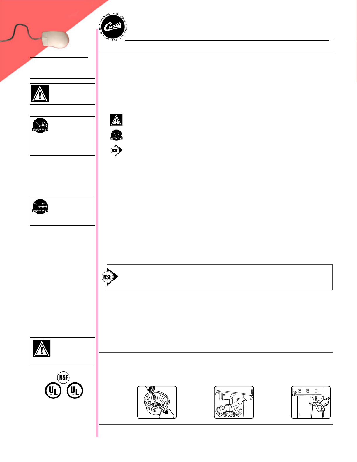
2. Place empty airpot(not included) under brewcone.
3. Place filter in Brewcone.
4. Pour ground
coffee into
brewcone.
5. Position
brewcone into
brew rails.
6. Press Brew
button.
Brewing
will begin
immediately.
FOR THE LATEST SPECIFICATIONS AND INFORMATION GO TO
WWW.WILBURCURTIS.COM
1
Page 2
STEPS TO
PROGRAMMING
PROGRAMMING ONLY REQUIRED IF FACTORY SETTINGS MUST BE CHANGED
Changing the ADS™ System Program
WARNING These steps involve
working with hot water. Scalding
may occur if care is not taken
against spilling.
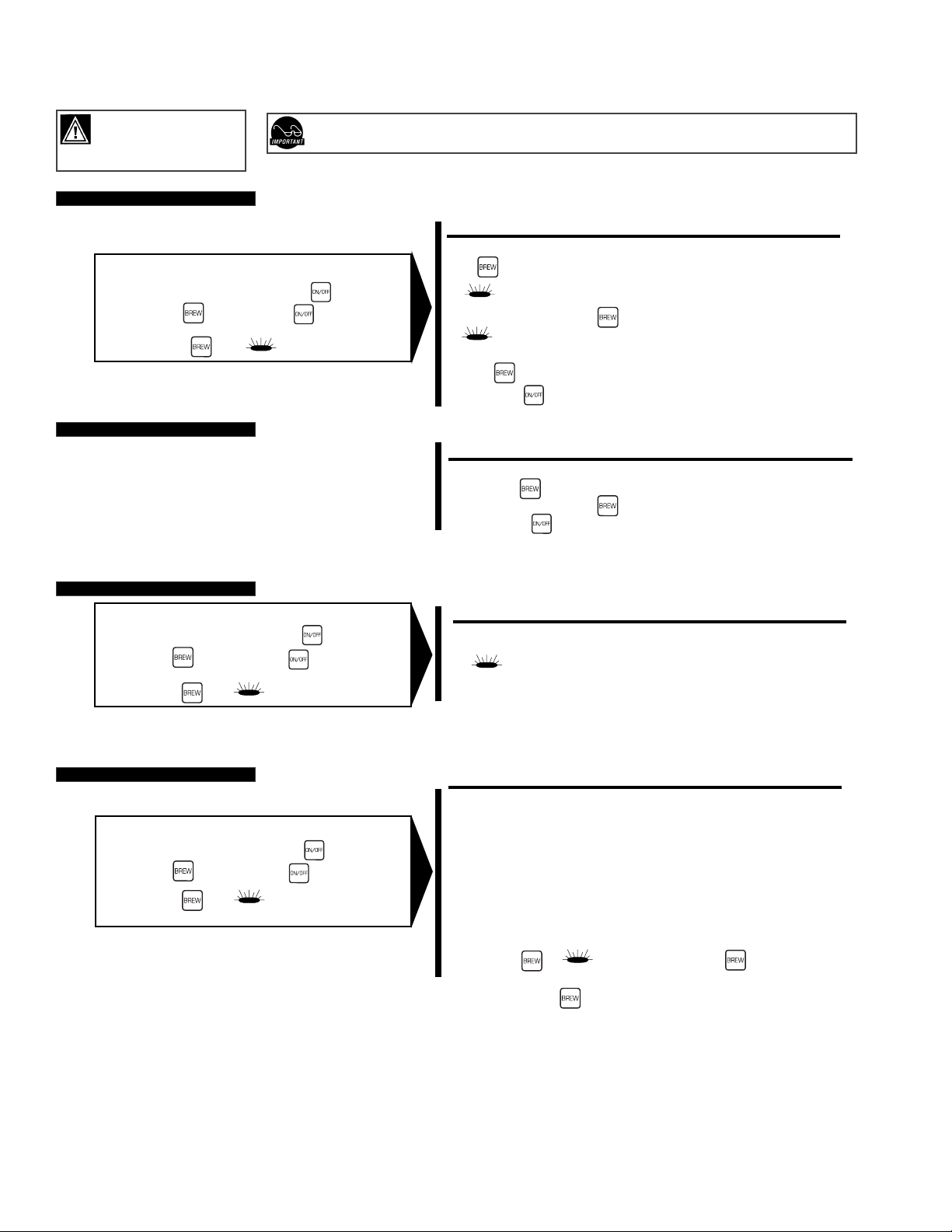
ENTERING THE PROGRAM MODE #1
Turn OFF the power from the Control Panel by pressing .
Press and HOLD and press and RELEASE .
Continue HOLDING until starts blinking; RELEASE.
IMPORTANT – Before entering the program mode, allow the unit to reach brewing temperature, then press the BREW
button to dispense at least 12 ounces of water. This is to clear any air that may be trapped within the water lines.
NOTE:NOTE:
NOTE:
For ALL functions you must first enter the programming mode.
NOTE:NOTE:
Brew Temperature – Factory Pre-Set to 200°F
Function to set brew temperature, 170° to 204°F. Brew temperature will be indicated by READY-TO-BREW light blinking.
CONFIRM/RESET BREW TEMPERATURE - Factory Preset to 200º
ENTER THE PROGRAMMING MODE #1:
Press for two seconds, then RELEASE.
will start blinking. Each blink equals 2º F, starting at 170º.
READY TO BREW
To change Temperature, press and HOLD .
.
will start QUICK flashing. Each QUICK flash equals 2º F.
READY TO BREW
READY TO BREW
After reaching 204º, temperature starts over at 170º.
RELEASE when the desired temperature is reached.
To set and exit, press .
BREW VOLUME - Factory Preset to Brewer Requirements
CHANGE BREW VOLUME
ENTER THE PROGRAMMING MODE #1
Press and HOLD until hot water starts running from sprayhead; then RELEASE.
When desired volume is reached, press again to stop flow.
To set and exit, press .
BREW CYCLE COUNTER
ENTER THE PROGRAM MODE #2
Turn OFF the power from the Control Panel by pressing .
Press and HOLD and press and RELEASE .
Continue HOLDING until STOPS blinking; RELEASE.
READY TO BREW
LOW TEMPERATURE BREW LOCKOUT (DELTA) – Factory Preset to Delta 3
ENTER THE PROGRAM MODE #3
Turn OFF the power from the Control Panel by pressing .
Press and HOLD and press and RELEASE .
Continue HOLDING until stops blinking and remains on;
RELEASE.
READY TO BREW
TO ACCESS BREW CYCLE COUNTER
ENTER THE PROGRAMMING MODE #2:
will now start a pattern of LONG and SHORT blinks.
READY TO BREW
This pattern identifies the number of brew cycles. SHORT blinks indicate the brew number from one [1] to nine [9].
LONG blinks separate the 1’s, 10’s, 1,000’s and 10,000’s.
ENTER THE PROGRAMMING MODE #3
This mode will give you a choice of minimum brew temperatures.
Delta 1 Delta 1
Delta 1 allows you to brew within 5 degrees from set temperature. This provides for consistent brew
Delta 1 Delta 1
temperature and consistent water density. If Delta 1 is used, run one half decanter first, cancel and
discard water. Enter program mode #1 and change brew volume to 1/2” below collar of decanter (one
small finger width).
Delta 2 Delta 2
Delta 2 allows you to brew within 15 degrees from set temperature. If Delta 2 is used, run 3/4 of a
Delta 2 Delta 2
decanter first, cancel and discard water. Enter program mode #1 and change brew volume to 3/4”
below collar of decanter (between one and two small finger widths).
Delta 3 Delta 3
Delta 3 (this is factory setting) will allow you to brew at any temperature. Back to back brewing is only
Delta 3 Delta 3
possible in this mode. If Delta 3 is used, run one half decanter first, cancel and discard water.
Enter program mode #1 and change brew volume to 1” below collar of decanter (two small finger
widths). The brew cone must be empty without a filter. This will ensure proper operation at all brew
rates.
Press and HOLD until gives off one quic flash, then release . You have now added a blink to
your blining light pattern.
By pressing and holding the again, you add another blink.
READY TO BREW
2
Page 3

PARTS
DIAGRAMS
D1000APD1000AP
D1000AP
D1000APD1000AP
33
3
33
22
2
22
44
4
44
Illustrated Parts List – D1000APIllustrated Parts List – D1000AP
Illustrated Parts List – D1000AP
Illustrated Parts List – D1000APIllustrated Parts List – D1000AP
NN
PP
art Nart N
Nº
P
NN
PP
WC-5421
2020
20
2020
1919
19
11
1
11
1010
10
1010
1111
11
1111
55
5
55
66
6
66
88
8
88
77
7
77
1313
13
1313
1212
12
99
9
99
1212
2828
28
2828
14
1919
2020
20
2020
1818
18
1818
99
9
99
1010
10
1010
2121
21
2121
2222
22
2222
1414
1414
2727
27
2727
2323
23
2323
1
2
WC-1809
3
WC-1806
WC-3316
4
5
WC-39193
6
WC-2936
WC-39017
7
8
WC-6221
9
1717
17
1717
WC- 817
WC- 889
10
11
WC-5310
12
WC- 847
WC- 683
13
14
WC-3502
14A
WC-3503*
WC-3518*
14B
15
WC-5231
16
WC-1438-101
WC- 102
17
18
WC-3763
19
WC- 833
WC-3765
20
21
WC-5661
22
WC-5502
WC - 934
23
24
WC-43055
25
WC- 522
WC-43058
26
27
WC-4382
28
WC-8560
WC-29046
29
* Used in newer D1000AP Brewers (14A front, 14B back legs).
DescriptionDescription
art Nº
Description
art Nart N
DescriptionDescription
COVER, TOP
FAUCET, HOT WATER W/JAM NUT
SEAT CUP, SILICONE
BREW CONE, W/HANDLE ASSY 7 1/8", S/S
MEMBRANE CONTROL PANEL D1000AP
SPRAYHEAD RED (.131 DIA)
LABEL, "TO REDUCE RISK..."
GRID, DRIP TRAY AIRPOT BREWERS
VALVE, DUMP RIGHT 120V
VALVE, DUMP LEFT 120V
TUBING, SILICONE, 5/16" I.D. (PER FT)
VALVE, INLET, 2 GPM, 120V
CONTROL BOARD, D1000AP 120V
LEG, SCREW BUMPER 8-32 STUD
LEG, 3/8-16 STUD SCREW
LEG, GLIDE 3/8-16 STUD SCREW
COMPOUND, SILICONE 5 OZ TUBE
SENSOR, TEMPERATURE TANK
SWITCH, TOGGLE SPST 25A 125/250VAC
KIT, DUMP VALVE FOR WC-817/WC-889
WASHER, FLOW, .75 GPM
KIT, REPAIR WATER INLET VALVE
LID ASSY, HEATING TANK
PROBE, WATER LEVEL ASSY
HEATING ELEMENT, 2500 WATT, 220V
GUARD, SHOCK, RESET THERMOSTAT
THERMOSTAT, RESET, WC-508R
PLUG, TANK DRAIN, PP RED
GUARD, SHOCK HEATING ELEMENT
HEAT SINK, D1000AP
TEE, INLET PLASTIC GEN USE
D500APD500AP
D500AP
D500APD500AP
1515
15
1515
1616
16
1616
2525
25
2525
2424
24
2424
Illustrated Parts List – D500APIllustrated Parts List – D500AP
Illustrated Parts List – D500AP
Illustrated Parts List – D500APIllustrated Parts List – D500AP
NN
PP
art Nart N
Nº
NN
1
2
3
4
5
6
7
8
9
10
11
12
13
14
15
16
17
18
19
20
21
22
23
24
25
26
27
P
PP
WC-3621
WC-1809
WC- 687
WC-39164
WC-5450
WC-5310
WC-2977
WC- 817
WC-2936
WC- 826
WC-3503
WC- 102
WC-6221
WC-3763
WC-3765
WC- 830
WC-54063
WC-5851
WC-43062
WC-1438
WC-5502-01
WC-4394
WC- 904-04
WC- 522
WC-43058
WC-43055
WC-5231
DescriptionDescription
art Nº
Description
art Nart N
DescriptionDescription
BREWCONE, UNIV7 1/8" BLK PLASTIC
FAUCET, HOT WATER W/JAM NUT
KIT, CONTROL BOARD 120/220V D500AP
MEMBRANE CNTRL PNL (CURTIS LOGO)
COVER, TOP
TUBING, SILICONE, 5/16" I.D. ( 1 FT.)
FITTING ASSY, SPRAYHEAD
VALVE, DUMP RIGHT 120V
SPRAYHEAD, RED (.131 DIA.)
VALVE, 1.15 GPM 120V
LEG, SCREW BUMPER 3/8-16 STD
SWITCH, TOGGLE 125/250 VAC RESISTIVE
GRID, DRIP TRAY AIRPOT
KIT, VALVE REPAIR USE ON WC817
KIT, VALVE REPAIR USE ON WC-826
WASHER, FLW ½” 1.0 GPM USE W/WC-826
TANK COMPLETE, D500AP 120V
COVER, TANK W/NOTCHES
GASKET, HEATING TANK
SENSOR, TEMPERATURE TANK
PROBE ASSY, WATER LEVEL
GUARD, SHOCK HEATING ELEMENT
ELEMENT, HEATING 16KW 120V
THERMOSTAT RESET
PLUG, TANK DRAIN, PP RED
GUARD, SHOCK RESET THERMOSTAT
COMPOUND, SILICONE 5 OZ TUBE
3
Page 4

ELECTRICALELECTRICAL
ELECTRICAL
ELECTRICALELECTRICAL
SCHEMASCHEMA
SCHEMA
SCHEMASCHEMA
TICSTICS
TICS
TICSTICS
D1000AP-10D1000AP-10
D1000AP-10
D1000AP-10D1000AP-10
D500AP-10D500AP-10
D500AP-10
D500AP-10D500AP-10
4
Page 5

Product Warranty Information
The Wilbur Curtis Company certifies that its products are free from defects in material and workmanship under normal use. The following limited warranties and conditions
apply:
3 3
3 Years, Parts and Labor, from Original Date of Purchase on digital control boards
3 3
2 2
2 Years, Parts, from Original Date of Purchase on all other electrical components, fittings and tubing.
2 2
1 1
1 Year, Labor, from Original Date of Purchase on all electrical components, fittings and tubing.
1 1
..
.
..
Additionally, the Wilbur Curtis Company warrants its Grinding Burrs for Forty (40) months from date of purchase or 40,000 pounds of coffee, whichever comes first. Stainless
Steel components are warranted for two (2) years from date of purchase against leaking or pitting and replacement parts are warranted for ninety (90) days from date of
purchase or for the remainder of the limited warranty period of the equipment in which the component is installed.
All in-warranty service calls must have prior authorization. For Authorization, call the Technical Support Department at 1-800-995-0417. Effective date of this policy is April
1, 2003.
Additional conditions may apply. Go to www.wilburcurtis.com to view the full product warranty information.
CONDITIONS & EXCEPTIONS
The warranty covers original equipment at time of purchase only. The Wilbur Curtis Company, Inc., assumes no responsibility for substitute replacement parts installed on Curtis
equipment that have not been purchased from the
Wilbur Curtis Company, Inc. The Wilbur Curtis Company will not accept any responsibility if the following conditions are not met. The warranty does not cover and is void under
the following circumstances:
1)1)
Improper operation of equipment: Improper operation of equipment:
1)
Improper operation of equipment: The equipment must be used for its designed and intended purpose and function.
1)1)
Improper operation of equipment: Improper operation of equipment:
2)2)
Improper installation of equipment: Improper installation of equipment:
2)
Improper installation of equipment: This equipment must be installed by a professional technician and must comply with all local electrical, mechanical and
2)2)
Improper installation of equipment: Improper installation of equipment:
plumbing codes.
3)3)
Improper voltage: Improper voltage:
3)
Improper voltage: Equipment must be installed at the voltage stated on the serial plate supplied with this equipment.
3)3)
Improper voltage: Improper voltage:
4)4)
Improper water supply: Improper water supply:
4)
Improper water supply: This includes, but is not limited to, excessive or low water pressure, and inadequate or fluctuating water flow rate.
4)4)
Improper water supply: Improper water supply:
5)5)
Adjustments and cleaning: Adjustments and cleaning:
5)
Adjustments and cleaning: The resetting of safety thermostats and circuit breakers, programming and temperature adjustments are the responsibility of the
5)5)
Adjustments and cleaning: Adjustments and cleaning:
equipment owner. The owner is responsible for proper cleaning and regular maintenance of this equipment.
6)6)
DamaDama
6)
6)6)
7)7)
7)
7)7)
ged in transit:ged in transit:
Dama
ged in transit:
DamaDama
ged in transit:ged in transit:
Abuse or neglect (including failure to periodically clean or remove lime accumulations): Abuse or neglect (including failure to periodically clean or remove lime accumulations):
Abuse or neglect (including failure to periodically clean or remove lime accumulations): Manufacturer is not responsible for variation in equipment
Abuse or neglect (including failure to periodically clean or remove lime accumulations): Abuse or neglect (including failure to periodically clean or remove lime accumulations):
operation due to excessive lime or local water conditions. The equipment must be maintained according to the manufacturer’s recommendations.
8)8)
Replacement of items subject to normal use and wear: Replacement of items subject to normal use and wear:
8)
Replacement of items subject to normal use and wear: This shall include, but is not limited to, light bulbs, shear disks, “0” rings, gaskets, silicone tube,
8)8)
Replacement of items subject to normal use and wear: Replacement of items subject to normal use and wear:
canister assemblies, whipper chambers and plates, mixing bowls, agitation assemblies and whipper propellers.
9)9)
Repairs and/or Replacements Repairs and/or Replacements
9)
Repairs and/or Replacements are subject to our decision that the workmanship or parts were faulty and the defects showed up under normal use. All labor shall
9)9)
Repairs and/or Replacements Repairs and/or Replacements
be performed during regular working hours. Overtime charges are the responsibility of the owner. Charges incurred by delays, waiting time, or operating restrictions that
hinder the service technician’s ability to perform service is the responsibility of the owner of the equipment. This includes institutional and correctional facilities. The
Wilbur Curtis Company will allow up to 100 miles, round trip, per in-warranty service call.
Equipment damaged in transit is the responsibility of the freight company and a claim should be made with the carrier.
RETURN MERCHANDISE RETURN MERCHANDISE
RETURN MERCHANDISE
RETURN MERCHANDISE RETURN MERCHANDISE
AUTHORIZAAUTHORIZA
AUTHORIZA
AUTHORIZAAUTHORIZA
TION:TION:
TION:
All claims under this warranty must be submitted to the Wilbur Curtis Company Technical Support Department prior to
TION:TION:
performing any repair work or return of this equipment to the factory. All returned equipment must be repackaged properly in the original carton. No units will be
accepted if they are damaged in transit due to improper packaging.
AUTHORIZAAUTHORIZA
AUTHORIZA
AUTHORIZAAUTHORIZA
TION (RMA).TION (RMA).
TION (RMA).
TION (RMA).TION (RMA).
RMA NUMBER MUST BE MARKED ON RMA NUMBER MUST BE MARKED ON
RMA NUMBER MUST BE MARKED ON
RMA NUMBER MUST BE MARKED ON RMA NUMBER MUST BE MARKED ON
NO UNITS OR PARTS WILL BE ACCEPTED WITHOUT A RETURN MERCHANDISENO UNITS OR PARTS WILL BE ACCEPTED WITHOUT A RETURN MERCHANDISE
NO UNITS OR PARTS WILL BE ACCEPTED WITHOUT A RETURN MERCHANDISE
NO UNITS OR PARTS WILL BE ACCEPTED WITHOUT A RETURN MERCHANDISENO UNITS OR PARTS WILL BE ACCEPTED WITHOUT A RETURN MERCHANDISE
THE CARTHE CAR
THE CAR
THE CARTHE CAR
TON OR SHIPPING LABEL.TON OR SHIPPING LABEL.
TON OR SHIPPING LABEL.
TON OR SHIPPING LABEL.TON OR SHIPPING LABEL.
All in-warranty service calls must be performed
by an authorized service agent. Call the Wilbur Curtis Technical Support Department to find an agent near you.
WILBUR CURTIS CO., INC.
6913 Acco St., Montebello, CA 90640-5403 USA
Phone: 800/421-6150 Fax: 323-837-2410
Technical Support Phone: 800/995-0417 (M-F 5:30A - 4:00P PST) E-Mail: techsupport@wilburcurtis.com
Web Site: www.wilburcurtis.com
FOR THE LATEST SPECIFICATION INFORMATION GO TO WWW.WILBURCURTIS.COM
Printed in U.S.A. 1/04 F-2070-S Rev A
5
1/23/04 . 12.8 . ecn 6372 rev A
10/2/01. 10.6 . edr 3132 rev NC
 Loading...