

Page 1

Operating instructions
Betriebsanleitung
Mode d'emploi
Manual de instrucciones
Gas-actuated thermometer with electrical output
signal, model TGT73
Gasdruck-Thermometer mit elektrischem
Ausgangssignal, Typ TGT73
Thermomètre à dilatation de gaz avec signal de sortie
électrique, type TGT73
Termómetro de dilatación de gas con señal de salida
eléctrica, modelo TGT73
Model TGT73.100
GB
D
F
E
Page 2

Operating instructions model TGT73
GB
Page 3 - 24
Betriebsanleitung Typ TGT73
D
Mode d'emploi type TGT73
F
Manual de instrucciones modelo TGT73
E
© 2012 WIKA Alexander Wiegand SE & Co. KG
All rights reserved. / Alle Rechte vorbehalten.
WIKA® is a registered trademark in various countries.
WIKA® ist eine geschützte Marke in verschiedenen Ländern.
Prior to starting any work, read the operating instructions!
Keep for later use!
Vor Beginn aller Arbeiten Betriebsanleitung lesen!
Zum späteren Gebrauch aufbewahren!
Lire le mode d‘emploi avant de commencer toute opération !
A conserver pour une utilisation ultérieure !
¡Leer el manual de instrucciones antes de comenzar cualquier trabajo!
¡Guardar el manual para una eventual consulta!
2
WIKA operating instructions model TGT73
Seite 25 - 44
Page 45 - 66
Página 67 - 86
14028755.02 08/2012 GB/D/F/E
Page 3

Contents
Contents
1. General information 4
2. Safety 6
3. Specications 8
4. Design and function 10
5. Transport, packaging and storage 11
6. Commissioning, operation 13
7. Mounting instructions for contact bulb 16
8. Electrical connection 18
9. Maintenance and cleaning 19
10. Faults 20
11. Dismounting, return and disposal 21
Appendix 1: EC declaration of conformity 23
Declarations of conformity can be found online at www.wika.com.
GB
14028755.02 08/2012 GB/D/F/E
WIKA operating instructions model TGT73 3
Page 4

1. General information
1. General information
■
The intelliTHERM model TGT73 gas-actuated thermometer
GB
described in these operating instructions has been designed and
manufactured using state-of-the-art technology. All components
are subject to stringent quality and environmental criteria during
production. Our management systems are certied to ISO 9001
and ISO 14001.
■
These operating instructions contain important information on
handling the instrument. Working safely requires that all safety
instructions and work instructions are observed.
■
Observe the relevant local accident prevention regulations and
general safety regulations for the instrument's range of use.
■
The operating instructions are part of the product and must be kept
in the immediate vicinity of the instrument and readily accessible to
skilled personnel at any time.
■
Skilled personnel must have carefully read and understood the
operating instructions, prior to beginning any work.
■
The manufacturer's liability is void in the case of any damage
caused by using the product contrary to its intended use,
non-compliance with these operating instructions, assignment
of insuciently qualied skilled personnel or unauthorised
modications to the instrument.
■
The general terms and conditions contained in the sales
documentation shall apply.
■
Subject to technical modications.
■
Further information:
- Internet address:
- Relevant data sheet: TV 17.10
www.wika.de / www.wika.com
4 WIKA operating instructions model TGT73
14028755.02 08/2012 GB/D/F/E
Page 5

1. General information
Explanation of symbols
WARNING!
... indicates a potentially dangerous situation which can
result in serious injury or death if not avoided.
CAUTION!
... indicates a potentially dangerous situation which can
result in light injuries or damage to the equipment or the
environment if not avoided.
Information
… points out useful tips, recommendations and
information for ecient and trouble-free operation.
WARNING!
... indicates a potentially dangerous situation that can
result in burns, caused by hot surfaces or liquids, if not
avoided.
GB
14028755.02 08/2012 GB/D/F/E
WIKA operating instructions model TGT73 5
Page 6

2. Safety
2. Safety
WARNING!
GB
2.1 Intended use
The gas-actuated thermometer is mainly used in the process industry
to monitor and control process temperatures.
Before installation, commissioning and operation, ensure
that the appropriate gas-actuated thermometer has been
selected in terms of measuring range, design and specic
measuring conditions. The compatibility of the wetted
parts of the process connection (thermowell, stem etc.)
with the medium must be tested.
Non-observance can result in serious injury and/or
damage to the equipment.
WARNING!
This is protection class 3 equipment for connection at low
voltages, which are separated from the power supply or
voltage by greater than AC 50 V or DC 120 V. Preferably,
a connection to an SELV or PELV circuit is recommended;
alternatively protective measures from HD 60346-4-41
(DIN VDE 0100-410).
Alternatively for North America:
The connection can be made in line with "Class 2
Circuits" or "Class 2 Power Units" in accordance with CEC
(Canadian Electrical Code) or NEC (National Electrical
Code).
Further important safety instructions can be found in the
individual chapters of these operating instructions.
The instrument has been designed and built solely for the intended
use described here, and may only be used accordingly.
6 WIKA operating instructions model TGT73
14028755.02 08/2012 GB/D/F/E
Page 7

2. Safety
The technical specications contained in these operating instructions
must be observed. Improper handling or operation of the instrument
outside of its technical specications requires the instrument to be
taken out of service immediately and inspected by an authorised
WIKA service engineer.
The manufacturer shall not be liable for claims of any type based on
operation contrary to the intended use.
2.2 Personnel qualication
WARNING!
Risk of injury if qualication is insucient!
Improper handling can result in considerable injury and
damage to equipment.
■
The activities described in these operating instructions
may only be carried out by skilled personnel who have
the qualications described below.
■
Keep unqualied personnel away from hazardous
areas.
Skilled personnel
Skilled personnel are understood to be personnel who, based on
their technical training, knowledge of measurement and control
technology and on their experience and knowledge of countryspecic regulations, current standards and directives, are capable
of carrying out the work described and independently recognising
potential hazards.
GB
2.3 Special hazards
WARNING!
Residual media in the dismounted gas-actuated
thermometer can result in a risk to personnel, the
environment and equipment. Take sucient precautionary
measures.
14028755.02 08/2012 GB/D/F/E
WIKA operating instructions model TGT73 7
Page 8

2. Safety / 3. Specications
2.4 Product label
Model
GB
Before mounting and commissioning the instrument,
ensure you read the operating instructions!
CE, Communauté Européenne
Instruments bearing this mark comply with the relevant
European directives.
3. Specications
Gas-actuated thermometer model TGT73
Measuring element Inert gas expansion system
Nominal size 100, 160
Instrument version Back mount (axial)
Permissible ambient temperature 0 ... 40 °C
Working range
■
Continuous load (1 year)
■
short term (max. 24 h)
Case, ring
Stem, process connection
Ingress protection
8 WIKA operating instructions model TGT73
Lower mount (radial)
Back mount, adjustable stem and dial
Instruments with capillaries
Measuring range (EN 13190)
Scale range (EN 13190)
Stainless steel
Stainless steel 1.4571
IP 65 per IEC 60529
Date of manufacture
14028755.02 08/2012 GB/D/F/E
Page 9

3. Specications
Electrical data
Power supply U
Inuence of power supply ≤ 0.1 % of full scale value/10 V
Permissible residual ripple ≤ 10 % ss
Output signal, variant I
Permissible max. load R
Eect of load ≤ 0.1 % of FS
Output signal, variant II 0 ... 10 V
Impedance at voltage output 0.5 Ω
Load capacity at voltage output 2 … 100 kΩ
Sensor sampling rate 600 ms
Linearity ≤ 1.0 % of span (limit point setting)
Output signal accuracy 0.2 % of FS (electronics only)
Resolution 0.15 % of FS (10 bit resolution at 360°)
Refresh rate (measuring rate) > 1/s
Input signal, angle of rotation 0 … 270 ∢ °
Long-term stability of electronics < 0.3 % of FS/a
Temperature error, electronics < 0.3 % of FS/10 K (in overall temperature
Warm-up time ≤ 5 min
Permissible ambient temperature
Permissible storage temperature
Electromagnetic compatibility
(EMC)
Electrical connection via angular connector, 180°
Ingress protection IP 65 to IEC 60529
B
DC 12 ≤ UB ≤ 30 V
4 … 20 mA, 2-wire, passive, per NAMUR NE43
RA ≤ (UB - 12 V)/0.02 A with RA in Ω and U
A
in V, however max. 600 Ω
range)
0 ... 40 °C
-40 … +70 °C without liquid damping
-20 … +70 °C with liquid damping
EMC directive 2004/108/EC, EN 61326
emission (group 1, class B) and interference
immunity (industrial application)
rotatable, max. 1,5 mm², cable
protection, M20 x 1.5 cable gland,
cable outer diameter 7 ... 13 mm,
incl. strain relief
Protection against reverse polarity and
overvoltage
GB
B
14028755.02 08/2012 GB/D/F/E
WIKA operating instructions model TGT73 9
Page 10

3. Specications / 4. Design and function
Designation of terminal
connectors dependent on the
output signal variant
GB
Terminal
Type
1
2
3
4
5
6
Variant I
4 ... 20 mA
GND
I+
reserved
reserved
reserved
reserved
For further specications see WIKA data sheet TV 17.10 and the
order documentation.
4. Design and function
4.1 Description
The gas-actuated thermometer consists of a stem, capillary, Bourdon
tube and transmitter in the casing. These parts are combined to form
a single unit. The entire measuring system is lled with an inert gas
under pressure.
Any change in temperature causes a change in internal pressure in
the stem, and thus a change in the shape of the pressure element.
This motion is converted, via a mechanical movement, into a
rotational motion. A magnet on the pointer shaft rotates proportionally
to the instrument pointer as a direct linear function of the process
temperature. The downstream electronics detect the rotational motion
of the magnet in the display range.
A magnetic-eld dependent rotational sensor picks up this change on
the electronics side, contact-free, wear-free and without reaction on
the pressure element.
Variant II
0 ... 10 V
GND
UB+
U
out
reserved
reserved
reserved
10 WIKA operating instructions model TGT73
14028755.02 08/2012 GB/D/F/E
Page 11

4. Design and function / 5. Transport ...
The rotational motion is converted into an electrical signal. The
electronics are factory set to the standard 4 ... 20 mA passive or
0 ... 10 V output signal. The span of the electrical output signal
corresponds to the measuring span on the dial.
Through these two standard electrical output signals, this instrument
can be set to almost any range in the industry.
Thermometers from the intelliTHERM range with transmitters
combine all the advantages of a local mechanical display with the
industry‘s requirements for electrical signal transmission and a
modern measured value registration.
Variations in the ambient temperature acting on the case are
compensated for by a bimetal element mounted between the
movement and the Bourdon tube.
Scale ranges with accuracy class 1 per EN 13190
between -200 ... +700 °C
4.2 Scope of delivery
Cross-check the scope of delivery with the delivery note.
5. Transport, packaging and storage
5.1 Transport
Check the gas-actuated thermometer for any damage that may
have been caused by transport. Obvious damage must be reported
immediately.
GB
5.2 Packaging
Do not remove packaging until just before mounting.
Keep the packaging as it will provide optimum protection during
transport (e.g. change in installation site, sending for repair).
14028755.02 08/2012 GB/D/F/E
WIKA operating instructions model TGT73 11
Page 12

5. Transport, packaging and storage
5.3 Storage
Permissible conditions at the place of storage:
Storage temperature: -40 … +70 °C (EN 13190) without liquid damping
GB
Avoid exposure to the following factors:
■
Direct sunlight or proximity to hot objects
■
Mechanical vibration, mechanical shock (putting it down hard)
■
Soot, vapour, dust and corrosive gases
■
Potentially explosive environments, ammable atmospheres
Store the gas-actuated thermometer in its original packaging in
a location that fulls the conditions listed above. If the original
packaging is not available, pack and store the thermometer as
described below:
1. Wrap the instrument in an antistatic plastic lm.
2. Place the instrument, along with shock-absorbent material, in the
packaging.
3. If stored for a prolonged period of time (more than 30 days), place a
bag containing a desiccant inside the packaging.
WARNING!
Before storing the instrument (following operation),
remove any residual media. This is of particular
importance if the medium is hazardous to health, e.g.
caustic, toxic, carcinogenic, radioactive, etc..
The use of liquid damping is always recommended for
temperatures near the dew point (±1 °C around 0 °C).
-20 … +70 °C (EN 13190) with liquid damping
12 WIKA operating instructions model TGT73
14028755.02 08/2012 GB/D/F/E
Page 13

6. Commissioning, operation
6. Commissioning, operation
When screwing the instruments in, the force required to do this must
not be applied through the casing, but only through the spanner ats
provided for this purpose, and using a suitable tool.
Installation with
open-ended spanner
■
If possible, the entire length of the stem should be exposed to the
temperature being measured. However, at least the length of the
active part that corresponds to the length of the gas expansion
vessel (active length).
■
In pipelines or other measuring points, the temperature probe must
be angled as far towards the ow as possible.
■
Errors in thermal conduction occur if the area where the
temperature is to be measured is so small, that the mass of the
temperature probe acts as thermal capacity. Errors in thermal
conduction may also occur if the immersion depth is insucient, if
the mounting ttings are connected to a good thermal conductor
(metal plate or similar) and there is a considerable dierence
in temperature between the measuring and mounting element
temperatures.
■
The dial casing must be mounted free from vibration. If necessary,
it is possible to isolate the instrument from the mounting point by
installing a exible connection line between the measuring point
and the thermometer and mounting the instrument on a suitable
bracket.
GB
14028755.02 08/2012 GB/D/F/E
WIKA operating instructions model TGT73 13
Page 14

6. Commissioning, operation
If this is not possible, the following limit values must not be exceeded:
Dry gauges: Frequency range < 150 Hz
GB
Acceleration < 0.7 g (7 m/s
Liquid-lled gauges: Frequency range < 150 Hz
Acceleration < 2 g (20 m/s
2
)
2
)
After mounting, set the compensating valve (if
available) from CLOSE to OPEN.
The liquid lling must be checked on a regular basis.
The liquid level must not drop below 75 % of the gauge diameter.
Heavy shocks, oscillations and vibrations lead to imprecise values,
increased wear in the movement, and fractures on welded or soldered
joints.
When mounting a gas-actuated thermometer that can be rotated
and swivelled, the specic instructions must be followed. In order to
set the indicator to the desired position, the following steps must be
taken:
1. The lock nut or union nut must be loosened at the process
connection.
2. The hexagon bolts and slotted screws at the swivel joint must be
loosened.
loosening
Make sure the screws on the
opposite side are loosened
as well!
14 WIKA operating instructions model TGT73
14028755.02 08/2012 GB/D/F/E
Page 15

6. Commissioning, operation
3. Position the indicator as required, tighten the hexagon bolts and
slotted screws, and nally tighten the lock nut or union nut rmly.
When using thermowells, they must be lled with a thermal contact
medium in order to reduce the heat transfer resistance between the
outer wall of the sensor and the inner wall of the thermowell. The
working temperature of the thermal compound is -40 ... +200 °C.
WARNING!
Do not ll hot thermowells. There is a risk of the oil
spraying out!
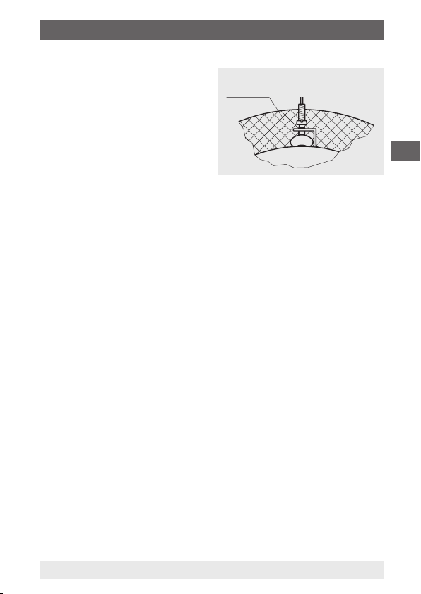
CAUTION!
When using thermowells, please
note that the stem must not touch
the bottom of the thermowell.
Due to the dierent coecients
of expansion of the materials, the
stem can bend at the bottom of the
thermowell.
Thermowell
Stem
Required safety
clearance
(For the formula for the calculation
of the insertion length, l1, see the
respective thermowell data sheet)
GB
14028755.02 08/2012 GB/D/F/E
WIKA operating instructions model TGT73 15
Page 16

7. Mounting instructions for contact bulb
7. Mounting instructions for contact bulb
The contact bulb has been designed for mounting on pipes or tanks.
When mounting this thermometer version, it must be ensured that the
GB
contact bulb is in contact with the measuring point over its complete
length. The basic requirements to ensure a perfect measurement
result is to retain good thermal contact between the skin mounted
contact bulb and the outside wall of the pipe or tank with minimal heat
loss to ambient from the skin mounted contact bulb and measuring
point.
Capillary
Bend protector
3107876.01
7.1 Mounting to pipes
The geometry of the contact
bulb has been designed for
pipes with external diameters
between 20 and 160 mm. The
skin mounted contact bulb should
have direct metallic contact with
the measuring point and have rm
contact with the surface of the
pipe. Where temperatures under
200 °C are to be expected, a heat conducting paste can be used to
optimise the heat transmission between skin mounted contact bulb
and pipe. Lagging must be applied where the skin mounted contact
bulb has been mounted, in order to avoid error due to heat loss.
This lagging must have sucient temperature resistance and is not
provided with the instrument.
16 WIKA operating instructions model TGT73
Tube clip mounting
Lagging
3107922.01
14028755.02 08/2012 GB/D/F/E
Page 17

7. Mounting instructions for contact bulb
7.2 Mounting to vessels
The geometry of the contact bulb
has been designed for vessels
Angle bracket mounting
Lagging
with an external radius up to
80 mm. If the mounting point
of the skin mounting contact
bulb on the tank has an external
radius greater than 80 mm,
we recommend the use of an
intermediate piece designed for the respective vessel diameter, made
of a material with good thermal conductivity. The contact bulb should
be fastened to the vessel by means of an angle bracket with clamping
screws, or any similar method. The skin mounted contact bulb should
have direct metallic contact with the measuring point and have rm
contact with the surface of the vessel.
A heat conductive paste can be used to optimise the heat
transmission between skin mounted contact bulb and the vessel,
if temperatures under 200 °C are to be expected. Lagging must be
applied where the skin mounted contact bulb has been mounted, in
order to avoid error due to heat loss. This lagging must have sucient
temperature resistance and is not provided with the instrument.
GB
3107930.01
14028755.02 08/2012 GB/D/F/E
WIKA operating instructions model TGT73 17
Page 18

8. Electrical connection
8. Electrical connection
The electrical connection of the transmitter is made through an
angular connector. The exact pin assignments can be found in the
GB
following drawings. In addition, the pin assignment, output signal and
the required power supply are stated on the product label.
Explanation of the terminal assignments used:
Positive terminal of the power supply
U
B+
0 V Negative terminal of the power supply
Sig+ Positive terminal of the output signal
Sig- Negative terminal of the output signal
The instruments must be connected to the equipotential bonding of
the plant.
Designation of terminal connectors
Terminals 1 and 2 are the connection terminals for the signal
output and the power supply, respectively. The terminal labelled
PE (protective earth) is internally connected to the casing. The
connections 3 to 6 or 4 to 6 in the 3-wire variant, should be left free
and must not be used as points (see also chapter 3 "Specications").
WARNING!
The gas-actuated thermometer with integrated rotary
encoder must be grounded through the thermometer
housing and through the ground terminal in the angular
connector.
18 WIKA operating instructions model TGT73
14028755.02 08/2012 GB/D/F/E
Page 19

8. Electrical connection / 9. Maintenance ...
2-wire system 3-wire system
e.g. 4 ... 20 mA e.g. 0 ... 10 V
Terminal box
Terminals 3, 4, 5 and 6:
only for internal use
Power supply
Power supply
Evaluation
(display)
Earth, connected
to case
UB+/Sig+
+0V/Sig-
As a power supply, an unstabilised DC power supply is sucient, with
a max. ripple of 10 % ss in the range of the specied power supply
limits. It is important to ensure that the applied power supply is at least
greater than the maximum required voltage drop from the external
display and evaluation units; i.e. the voltage at the transmitter must
not fall below 12 V.
9. Maintenance and cleaning
9.1 Maintenance
Gas-actuated thermometers with transmitters are maintenance-free!
The indicator should be checked once or twice every year. To do this
the instrument must be disconnected from the process and checked
using a temperature calibrator.
Repairs must only be carried out by the manufacturer.
Evaluation
(display)
Earth, connected
to case
UB+/Sig+
I
out/Uout
+0V/Sig-
Terminals 4, 5 and 6:
only for internal use
GB
14028755.02 08/2012 GB/D/F/E
WIKA operating instructions model TGT73 19
Page 20

9. Maintenance and cleaning / 10. Faults
9.2 Cleaning
CAUTION!
■
GB
10. Faults
Faults Causes Measures
No output signal No power supply or
Constant output
signal upon change in
temperature
Too high, constant
output signal upon
change in temperature
Signal span too small Power supply too low Rectify the power supply
20 WIKA operating instructions model TGT73
Clean the instrument with a moist cloth.
■
Wash or clean the dismounted instrument before
returning it in order to protect personnel and the
environment from exposure to residual media.
■
Residual media in the dismounted gas-actuated
thermometer can result in a risk to personnel,
the environment and equipment. Take sucient
precautionary measures.
For information on returning the instrument see chapter
11.2 "Return".
cable break
Transmitter incorrectly
connected
Electronics failure due to
too high power supply or
through external voltage
Power supply connected
the wrong way
(I = approx. 4.5 mA)
Transmitter fault Return the instrument to the
Electronics failure due to
too high power supply or
through external voltage
Load too high Stay within the max.
Check voltage supply
and cables. Replace any
defective components found
Check connections; correct
connections if necessary
Return the instrument to the
manufacturer for repair
Check connection, and if
necessary, swap terminals
1 and 2
manufacturer for repair
Return the instrument to the
manufacturer for repair
permissible load
14028755.02 08/2012 GB/D/F/E
Page 21

11. Dismounting, return and disposal
11. Dismounting, return and disposal
WARNING!
Residual media in the dismounted gas-actuated
thermometer can result in a risk to personnel, the
environment and equipment. Take sucient precautionary
measures.
11.1 Dismounting
WARNING!
Risk of burns!
Let the instrument cool down suciently before
dismounting! During dismounting there is a risk of
dangerously hot pressure media escaping.
11.2 Return
WARNING!
Absolutely observe the following when shipping the
instrument:
All instruments delivered to WIKA must be free from any kind
of hazardous substances (acids, leachate, solutions, etc.).
When returning the instrument, use the original packaging or a
suitable transport package.
To avoid damage:
1. Wrap the instrument in an antistatic plastic lm.
2. Place the instrument, along with shock-absorbent material, in the
packaging. Place shock-absorbent material evenly on all sides of
the shipping box.
3. If possible, place a bag containing a desiccant inside the packaging.
4. Label the shipment as carriage of a highly sensitive measuring
instrument.
GB
14028755.02 08/2012 GB/D/F/E
WIKA operating instructions model TGT73 21
Page 22

11. Dismounting, return and disposal
Information on returns can be found under the heading
"Service" on our local website.
GB
11.3 Disposal
Incorrect disposal can put the environment at risk.
Dispose of instrument components and packaging materials in an
environmentally compatible way and in accordance with the countryspecic waste disposal regulations.
22 WIKA operating instructions model TGT73
14028755.02 08/2012 GB/D/F/E
Page 23

Appendix 1: EC declaration of conformity
GB
14028755.02 08/2012 GB/D/F/E
WIKA operating instructions model TGT73 23
Page 24

GB
24 WIKA operating instructions model TGT73
14028755.02 08/2012 GB/D/F/E
Page 25

Inhalt
Inhalt
1. Allgemeines 26
2. Sicherheit 28
3. Technische Daten 30
4. Aufbau und Funktion 32
5. Transport, Verpackung und Lagerung 33
6. Inbetriebnahme, Betrieb 35
7. Montagehinweise für Anliegefühler 38
8. Elektrischer Anschluss 40
9. Wartung und Reinigung 41
10. Störungen 42
11. Demontage, Rücksendung und Entsorgung 43
Anlage 1: EG-Konformitätserklärung 23
Konformitätserklärungen nden Sie online unter www.wika.de.
D
14028755.02 08/2012 GB/D/F/E
WIKA Betriebsanleitung Typ TGT73
25
Page 26

1. Allgemeines
1. Allgemeines
■
Das in der Betriebsanleitung beschriebene Gasdruck-Thermometer intelliTHERM Typ TGT73 wird nach dem aktuellen Stand der
Technik konstruiert und gefertigt. Alle Komponenten unterliegen
während der Fertigung strengen Qualitäts- und Umweltkriterien.
D
Unsere Managementsysteme sind nach ISO 9001 und ISO 14001
zertiziert.
■
Diese Betriebsanleitung gibt wichtige Hinweise zum Umgang mit
dem Gerät. Voraussetzung für sicheres Arbeiten ist die Einhaltung
aller angegebenen Sicherheitshinweise und Handlungsanweisungen.
■
Die für den Einsatzbereich des Gerätes geltenden örtlichen Unfallverhütungsvorschriften und allgemeinen Sicherheitsbestimmungen
einhalten.
■
Die Betriebsanleitung ist Produktbestandteil und muss in unmittelbarer Nähe des Gerätes für das Fachpersonal jederzeit zugänglich
aufbewahrt werden.
■
Das Fachpersonal muss die Betriebsanleitung vor Beginn aller
Arbeiten sorgfältig durchgelesen und verstanden haben.
■
Die Haftung des Herstellers erlischt bei Schäden durch bestimmungswidrige Verwendung, Nichtbeachten dieser Betriebsanleitung, Einsatz ungenügend qualizierten Fachpersonals sowie
eigenmächtiger Veränderung am Gerät.
■
Es gelten die allgemeinen Geschäftsbedingungen in den Verkaufsunterlagen.
■
Technische Änderungen vorbehalten.
■
Weitere Informationen:
- Internet-Adresse:
- zugehöriges Datenblatt: TV 17.10
www.wika.de / www.wika.com
26 WIKA Betriebsanleitung Typ TGT73
14028755.02 08/2012 GB/D/F/E
Page 27

1. Allgemeines
Symbolerklärung
WARNUNG!
… weist auf eine möglicherweise gefährliche Situation hin,
die zum Tod oder zu schweren Verletzungen führen kann,
wenn sie nicht gemieden wird.
VORSICHT!
… weist auf eine möglicherweise gefährliche Situation
hin, die zu geringfügigen oder leichten Verletzungen bzw.
Sach- und Umweltschäden führen kann, wenn sie nicht
gemieden wird.
Information
… hebt nützliche Tipps und Empfehlungen sowie
Informationen für einen ezienten und störungsfreien
Betrieb hervor.
WARNUNG!
… weist auf eine möglicherweise gefährliche Situation
hin, die durch heiße Oberächen oder Flüssigkeiten zu
Verbrennungen führen kann, wenn sie nicht gemieden
wird.
D
14028755.02 08/2012 GB/D/F/E
WIKA Betriebsanleitung Typ TGT73
27
Page 28

2. Sicherheit
2. Sicherheit
D
WARNUNG!
Vor Montage, Inbetriebnahme und Betrieb sicherstellen,
dass das richtige Gasdruck-Thermometer hinsichtlich
Messbereich, Ausführung und spezischen Messbedingungen ausgewählt wurde. Die Verträglichkeit der
messstoberührten Bauteile des Prozessanschlusses
(Schutzrohr, Tauchrohr etc.) muss mit dem Messsto
geprüft werden.
Bei Nichtbeachten können schwere Körperverletzungen
und/oder Sachschäden auftreten.
WARNUNG!
Dies ist ein Betriebsmittel der Schutzklasse 3 zum
Anschluss an Kleinspannungen, die von der Netzspannung oder Spannung größer AC 50 V bzw. DC 120 V
getrennt sind. Zu bevorzugen ist ein Anschluss an
SELV- oder PELV-Stromkreise; alternativ ist eine Schutzmaßnahme aus HD 60346-4-41 (DIN VDE 0100-410) zu
empfehlen.
Alternativ für Nordamerika:
Der Anschluss kann auch an „Class 2 Circuits“ oder
„Class 2 Power Units“ gemäß CEC (Canadian Electrical
Code) oder NEC (National Electrical Code) erfolgen
Weitere wichtige Sicherheitshinweise benden sich in den
einzelnen Kapiteln dieser Betriebsanleitung.
2.1 Bestimmungsgemäße Verwendung
Das Gasdruck-Thermometer wird hauptsächlich in der Prozessindustrie eingesetzt, um die Temperatur des Prozesses zu überwachen und
zu regeln.
Das Gerät ist ausschließlich für den hier beschriebenen bestimmungsgemäßen Verwendungszweck konzipiert und konstruiert und
darf nur dementsprechend verwendet werden.
28 WIKA Betriebsanleitung Typ TGT73
14028755.02 08/2012 GB/D/F/E
Page 29

2. Sicherheit
Die technischen Spezikationen in dieser Betriebsanleitung sind
einzuhalten. Eine unsachgemäße Handhabung oder ein Betreiben
des Gerätes außerhalb der technischen Spezikationen macht die
sofortige Stilllegung und Überprüfung durch einen autorisierten
WIKA-Servicemitarbeiter erforderlich.
Ansprüche jeglicher Art aufgrund von nicht bestimmungsgemäßer
Verwendung sind ausgeschlossen.
2.2 Personalqualikation
WARNUNG!
Verletzungsgefahr bei unzureichender Qualikation!
Unsachgemäßer Umgang kann zu erheblichen Personenund Sachschäden führen.
■
Die in dieser Betriebsanleitung beschriebenen
Tätigkeiten nur durch Fachpersonal nachfolgend
beschriebener Qualikation durchführen lassen.
■
Unqualiziertes Personal von den Gefahrenbereichen
fernhalten.
Fachpersonal
Das Fachpersonal ist aufgrund seiner fachlichen Ausbildung, seiner
Kenntnisse der Mess- und Regelungstechnik und seiner Erfahrungen
sowie Kenntnis der landesspezischen Vorschriften, geltenden
Normen und Richtlinien in der Lage, die beschriebenen Arbeiten
auszuführen und mögliche Gefahren selbstständig zu erkennen.
D
2.3 Besondere Gefahren
WARNUNG!
Messstoreste im ausgebauten Gasdruck-Thermometer
können zur Gefährdung von Personen, Umwelt und
Einrichtung führen. Ausreichende Vorsichtsmaßnahmen
ergreifen.
14028755.02 08/2012 GB/D/F/E
WIKA Betriebsanleitung Typ TGT73
29
Page 30

2. Sicherheit / 3. Technische Daten
2.4 Typenschild
Typ
D
Herstellungsdatum
Vor Montage und Inbetriebnahme des Gerätes unbedingt
die Betriebsanleitung lesen!
CE, Communauté Européenne
Geräte mit dieser Kennzeichnung stimmen überein mit
den zutreenden europäischen Richtlinien.
3. Technische Daten
Gasdruck-Thermometer Typ TGT73
Messelement Gasdruck-Inertgasfüllung
Nenngröße 100, 160
Geräteausführung Anschlusslage rückseitig (axial)
Zul. Umgebungstemperatur 0 ... 40 °C
Verwendungsbereich
■
Dauerbelastung (1 Jahr)
■
kurzzeitig (max. 24 h)
Gehäuse, Ring
Tauchschaft, Prozessanschluss
Schutzart
30 WIKA Betriebsanleitung Typ TGT73
Anschlusslage unten (radial)
Anschlusslage rückseitig, dreh- und schwenkbar
Geräte mit Fernleitung
Messbereich (EN 13190)
Anzeigebereich (EN 13190)
CrNi-Stahl
CrNi-Stahl 1.4571
IP 65
nach IEC 60529
14028755.02 08/2012 GB/D/F/E
Page 31

3. Technische Daten
Elektrische Daten
Hilfsenergie U
Einuss der Hilfsenergie ≤ 0,1 % vom Endwert/10 V
Zulässige Restwelligkeit ≤ 10 % ss
Ausgangssignal, Variante I
Zulässige max. Bürde R
Bürdeneinuss ≤ 0,1 % vom EW
Ausgangssignal, Variante II 0 ... 10 V
Impedanz am Spannungs-
ausgang
Belastbarkeit Spannungs-
ausgang
Abtastrate Sensor 600 ms
Kennlinienabweichung ≤ 1,0 % d. Spanne (Grenzpunkteinstellung)
Genauigkeit Ausgangssignal 0,2 % vom EW (nur Elektronik)
Auösung 0,15 % vom EW (10 bit Auösung bei 360°)
Aktualisierungsrate (Messrate) > 1/s
Eingangssignal Drehwinkel 0 … 270 ∢ °
Langzeitstabilität Elektronik < 0,3 % vom EW/a
Temperaturfehler Elektronik < 0,3 % v. EW/10 K (im gesamten Temperatur-
Aufwärmzeit ≤ 5 min
Zul. Umgebungstemperatur
Zul. Lagertemperatur
Elektromagnetische
Verträglichkeit (EMV)
Elektrischer Anschluss über Winkelsteckverbinder, 180° verdrehbar,
Schutzart IP 65 nach IEC 60529
B
DC 12 ≤ UB ≤ 30 V
4 … 20 mA, 2 Leiter, passiv, nach NAMUR NE43
RA ≤ (UB - 12 V)/0,02 A mit RA in Ω und UB in V
A
jedoch max. 600 Ω
0,5 Ω
2 … 100 kΩ
bereich)
0 ... 40 °C
-40 … +70 °C ohne Flüssigkeitsdämpfung
-20 … +70 °C bei Flüssigkeitsdämpfung
EMV-Richtlinie 2004/108/EG, EN 61326
Emission (Gruppe 1, Klasse B) und Störfestigkeit
(industrieller Bereich)
max. 1,5 mm², Drahtschutz,
Kabelverschraubung M20 x 1,5,
Kabelaußendurchmesser 7 ... 13 mm,
inkl. Zugentlastung
Verpolungs- und Überspannungsschutz
D
14028755.02 08/2012 GB/D/F/E
WIKA Betriebsanleitung Typ TGT73
31
Page 32

3. Technische Daten / 4. Aufbau und Funktion
Belegung der Anschlussklemmen je nach Variante des
Ausgangssignals
D
Klemme
Art
1
2
3
4
5
6
Variante I
4 ... 20 mA
GND
I
+
reserviert
reserviert
reserviert
reserviert
Variante II
0 ... 10 V
GND
U
B+
U
out
reserviert
reserviert
reserviert
Weitere technische Daten siehe WIKA-Datenblatt TV 17.10 und
Bestellunterlagen.
4. Aufbau und Funktion
4.1 Beschreibung
Das Gasdruck-Thermometer besteht aus Tauchschaft, Kapillarleitung,
Rohrfeder und Ferngeber im Gehäuse. Diese Teile sind zu einer
Einheit verbunden. Das komplette Messsystem ist unter Druck mit
einem inerten Gas gefüllt.
Eine Temperaturänderung bewirkt im Tauchschaft eine Veränderung
des Innendruckes und somit die Form des Messgliedes.
Diese Bewegung wird über ein mechanisches Messwerk in eine
Drehbewegung umgesetzt. Ein auf der Zeigerachse aufgesetzter
Magnet dreht sich proportional mit dem Instrumentenzeiger in direkter
linearer Abhängigkeit zu der Prozesstemperatur. Die nachgeschaltete
Elektronik erfasst die Drehbewegung des Magneten im Anzeigebereich.
Ein magnetfeldabhängiger Drehwinkelsensor greift auf der elektrischen Seite diese Veränderung berührungslos ab und arbeitet somit
verschleißfrei.
32 WIKA Betriebsanleitung Typ TGT73
14028755.02 08/2012 GB/D/F/E
Page 33

4. Aufbau, Funktion / 5. Transport ...
Die Drehbewegung wird in ein elektrisches Ausgangssignal
umgesetzt. Werkseitig ist die Elektronik auf das normierte
Ausgangssignal 4 ... 20 mA passiv, oder 0 ... 10 V eingestellt.
Die Spanne des elektrischen Ausgangssignals entspricht der
Messspanne auf dem Zierblatt.
Durch die zwei normierten elektrischen Ausgangssignale ist diese
Gerätereihe in nahezu allen Bereichen der Industrie einsetzbar.
Das Thermometer mit Ferngeber aus der intelliTHERM-Reihe verbindet alle Vorteile einer mechanischen Anzeige vor Ort mit der Forderung nach einer elektrischen Signalübertragung für eine moderne
Messwerterfassung in der Industrie.
Schwankungen der Umgebungstemperatur auf das Gehäuse können
vernachlässigt werden, da zwischen dem Zeigerwerk und der
Messfeder ein Bimetallelement zur Kompensation eingebaut ist.
Anzeigebereiche bei Genauigkeitsklasse 1 nach EN 13190
zwischen -200 ... +700 °C
4.2 Lieferumfang
Lieferumfang mit dem Lieferschein abgleichen.
5. Transport, Verpackung und Lagerung
5.1 Transport
Das Gasdruck-Thermometer auf eventuell vorhandene Transportschäden untersuchen. Oensichtliche Schäden unverzüglich mitteilen.
D
5.2 Verpackung
Verpackung erst unmittelbar vor der Montage entfernen.
Die Verpackung aufbewahren, denn diese bietet bei einem Transport
einen optimalen Schutz (z. B. wechselnder Einbauort, Reparatursendung).
14028755.02 08/2012 GB/D/F/E
WIKA Betriebsanleitung Typ TGT73
33
Page 34

5. Transport, Verpackung und Lagerung
5.3 Lagerung
Zulässige Bedingungen am Lagerort:
Lagertemperatur: -40 … +70 °C (EN 13190) ohne Flüssigkeitsdämpfung
D
Folgende Einüsse vermeiden:
■
Direktes Sonnenlicht oder Nähe zu heißen Gegenständen
■
Mechanische Vibration, mechanischer Schock (hartes Aufstellen)
■
Ruß, Dampf, Staub und korrosive Gase
■
Explosionsgefährdete Umgebung, entzündliche Atmosphären
Das Gasdruck-Thermometer in der Originalverpackung an einem
Ort lagern, der die oben gelisteten Bedingungen erfüllt. Wenn die
Originalverpackung nicht vorhanden ist, dann das Thermometer wie
folgt verpacken und lagern:
1. Das Gerät in eine antistatische Plastikfolie einhüllen.
2. Das Gerät mit dem Dämmmaterial in der Verpackung platzieren.
3. Bei längerer Einlagerung (mehr als 30 Tage) einen Beutel mit
Trocknungsmittel der Verpackung beilegen.
-20 … +70 °C (EN 13190) bei Flüssigkeitsdämpfung
WARNUNG!
Vor der Einlagerung des Gerätes (nach Betrieb) alle
anhaftenden Messstoreste entfernen. Dies ist besonders
wichtig, wenn der Messsto gesundheitsgefährdend ist,
wie z. B. ätzend, giftig, krebserregend, radioaktiv, usw.
Empfohlen wird bei Temperaturen um den Taupunkt (±1 °C
um 0 °C) immer die Verwendung einer Flüssigkeitsdämpfung.
34 WIKA Betriebsanleitung Typ TGT73
14028755.02 08/2012 GB/D/F/E
Page 35

6. Inbetriebnahme, Betrieb
6. Inbetriebnahme, Betrieb
Beim Einschrauben der Geräte darf die dazu erforderliche Kraft nicht
über das Gehäuse aufgebracht werden, sondern mit geeignetem
Werkzeug nur über die dafür vorgesehenen Schlüsselächen.
Montage mit
Gabelschlüssel
■
Der Tauchschaft soll möglichst mit seiner ganzen Länge der zu
messenden Temperatur ausgesetzt sein. Mindestens aber die
Länge des aktiven Teils, welche der Länge des Gasausdehnungsgefäßes entspricht (aktive Länge).
■
Der Temperaturfühler muss in Rohrleitungen oder sonstigen
Messstellen der Strömungsrichtung möglichst schräg entgegengerichtet stehen.
■
Wärmeableitfehler entstehen, wenn der Messraum, dessen
Temperatur angezeigt werden soll, sehr klein ist, so dass sich die
Masse des Temperaturfühlers als Wärmekapazität bemerkbar
macht. Wärmeableitfehler können auch bei nicht genügender
Einbautiefe entstehen, wenn die Befestigungsarmatur an einem
guten Wärmeleiter (Metallplatten oder dergleichen) befestigt ist
und ein erheblicher Temperaturunterschied zwischen der Messund der Befestigungselement-Temperatur besteht.
■
Das Anzeigegehäuse muss erschütterungsfrei montiert werden.
Gegebenenfalls kann z. B. durch eine exible Verbindungsleitung
von der Messstelle zum Thermometer und die Befestigung über
eine Messgerätehalterung eine Entkopplung vom Einbauort
erreicht werden.
D
14028755.02 08/2012 GB/D/F/E
WIKA Betriebsanleitung Typ TGT73
35
Page 36

6. Inbetriebnahme, Betrieb
Falls dies nicht möglich ist, dürfen folgende Grenzwerte nicht
überschritten werden:
Ungefüllte Geräte: Frequenzbereich < 150 Hz
Beschleunigung < 0,7 g (7 m/s
D
Flüssigkeitsgefüllte Geräte: Frequenzbereich < 150 Hz
Beschleunigung < 2 g (20 m/s
Belüftungsventil (falls vorhanden) nach der
Montage von CLOSE auf OPEN stellen.
Die Flüssigkeitsfüllung ist regelmäßig zu überprüfen.
Der Flüssigkeitsspiegel darf nicht unter 75 % des Gerätedurchmessers
fallen.
Starke Erschütterungen, Schwingungen und Vibrationen führen zu
Anzeigeunsicherheiten, erhöhtem Verschleiß im Messwerk bzw.
Bruch an den Schweiß- oder Lötstellen.
Bei der Montage eines dreh- und schwenkbaren Gasdruck-Thermometers sind besondere Vorschriften zu beachten. Um die Anzeige
in die gewünschte Position zu bringen, müssen folgende Schritte
eingehalten werden:
1. Die Konter- oder Überwurfmutter muss am Prozessanschluss
gelöst sein.
2. Sechskant- und Schlitzschrauben müssen am Schwenkgelenk
gelöst sein.
lösen
Unbedingt auch die Schrauben der gegenüberliegenden
Seite lösen!
2
2
)
)
36 WIKA Betriebsanleitung Typ TGT73
14028755.02 08/2012 GB/D/F/E
Page 37

6. Inbetriebnahme, Betrieb
3. Anzeige positionieren, Sechskant- und Schlitzschrauben anziehen
und schließlich die Konter- oder Überwurfmutter fest anziehen.
Bei Verwendung von Schutzrohren ist möglichst durch Einfüllen eines
Wärmekontaktmittels der Wärmeübertragungswiderstand zwischen
Fühleraußenwand und Schutzrohrinnenwand zu reduzieren. Die
Arbeitstemperatur der Wärmeleitpaste beträgt -40 ... +200 °C.
WARNUNG!
Nicht in heiße Schutzrohre einfüllen. Gefahr durch herausspritzendes Öl!
VORSICHT!
Bei der Verwendung von Schutzrohren beachten, dass der
Tauchschaft nicht den Boden des
Schutzrohres berührt! Durch die
unterschiedlichen Ausdehnungskoezienten der Materialen, kann
sich der Tauchschaft am Boden
Schutzrohr
Tauchschaft
Benötigter
Sicherheitsabstand
des Schutzrohres verbiegen.
(Formeln zur Berechnung der
Einbaulänge l1 siehe entsprechendes Schutzrohrdatenblatt)
D
14028755.02 08/2012 GB/D/F/E
WIKA Betriebsanleitung Typ TGT73
37
Page 38

7. Montagehinweise für Anliegefühler
7. Montagehinweise für Anliegefühler
Der Anliegefühler ist vorgesehen zur Oberächenmontage an
Rohren und Behältern. Die Montage ist so durchzuführen, dass der
Anliegefühler über seine gesamte Länge auf der Messstelle auiegt.
D
Voraussetzung für ein einwandfreies Messergebnis ist eine gute
thermische Ankopplung des Anliegefühlers zur Rohraußenwand bzw.
Behälteraußenwand sowie eine möglichst geringe Wärmeableitung
der Messstelle und des Anliegefühlers an die Umgebung.
Kapillarleitung
Knickschutz
3107876.01
7.1 Montage an Rohren
Die Geometrie des Anliegefühlers ist abgestimmt auf Rohre
Rohrschellenmontage
Isolierung
mit einem Außendurchmesser
zwischen 20 und 160 mm. Zum
Befestigen des Anliegefühlers
am Rohr genügen Rohrschellen.
Der Anliegefühler sollte direkten metallischen Kontakt zur
Messstelle aufweisen und fest
auf der Oberäche des Rohres auiegen. Sofern die zu erwartenden Temperaturen unter 200 °C liegen, kann zur Optimierung des
Wärmeüberganges zwischen Anliegefühler und Rohr eine Wärmeleitpaste eingesetzt werden. Eine lsolierung muss an der Montagestelle
angebracht werden, um Wärmeableitfehler zu vermeiden. Diese
lsolierung muss ausreichend temperaturbeständig sein und gehört
nicht zum Lieferumfang.
38 WIKA Betriebsanleitung Typ TGT73
3107922.01
14028755.02 08/2012 GB/D/F/E
Page 39

7. Montagehinweise für Anliegefühler
7.2 Montage an Behältern
Die Geometrie des Anliegefühlers
ist abgestimmt auf Behälter-
Winkeleisenhalterung
Isolierung
außenradien bis 80 mm. Beträgt
an der Montagestelle des Anliegefühlers der Behälteraußenradius
mehr als 80 mm, empfehlen wir
das Verwenden eines auf den
jeweiligen Behälterdurchmesser
abgestimmten Zwischenteiles aus einem Material mit guter thermischer Leitfähigkeit. Zum Befestigen des Anliegefühlers am Behälter
kann z. B. eine Halterung aus Winkeleisen mit Anpressschrauben
eingesetzt werden. Der Anliegefühler sollte direkten metallischen
Kontakt zur Messstelle aufweisen und fest auf der Oberäche des
Behälters auiegen.
Zur Optimierung des Wärmeüberganges zwischen Anliegefühler und
Behälter kann eine Wärmeleitpaste eingesetzt werden, wenn die zu
erwartenden Temperaturen unter 200 °C liegen. Eine lsolierung muss
an der Montagestelle angebracht werden, um Wärmeableitfehler zu
vermeiden. Diese lsolierung muss ausreichend temperaturbeständig
sein und gehört nicht zum Lieferumfang.
3107930.01
D
14028755.02 08/2012 GB/D/F/E
WIKA Betriebsanleitung Typ TGT73
39
Page 40

8. Elektrischer Anschluss
8. Elektrischer Anschluss
Der elektrische Anschluss des Ferngebers wird über einen Winkelsteckverbinder hergestellt. Die genauen Anschlussbelegungen
können den nachfolgenden Zeichnungen entnommen werden.
D
Zusätzlich sind Anschlussbelegung, Ausgangssignal und erforderliche Hilfsenergie auf dem Typenschild vermerkt.
Bedeutung der verwendeten Klemmenbezeichnungen:
+ Plusklemme der Hilfsenergie
U
B
0 V Minusklemme der Hilfsenergie
Sig+ Plusklemme des Ausgangssignals
Sig- Minusklemme des Ausgangssignals
Die Geräte in den Potenzialausgleich der Anlage mit einbeziehen.
Belegung der Anschlussklemmen
Die Klemmen 1 und 2 sind die Anschlussklemmen für den Signalausgang bzw. für die Spannungsversorgung. Die mit PE (protective earth,
Schutzleiter) gekennzeichnete Klemme ist intern mit dem Gehäuse
verbunden. Die Anschlüsse 3 bis 6 bzw. 4 bis 6 bei der 3 LeiterVariante sind frei zu lassen und dürfen auch nicht als Stützpunkte
verwendet werden (siehe auch Kapitel 3 „Technische Daten“).
WARNUNG!
Das Gasdruck-Thermometer mit integriertem Drehwinkelferngeber muss über das Thermometergehäuse und
zusätzlich über die Erdungsklemme im Winkelsteckverbinder geerdet werden.
40 WIKA Betriebsanleitung Typ TGT73
14028755.02 08/2012 GB/D/F/E
Page 41

8. Elektrischer Anschluss / 9. Wartung und ...
2-Leiter-Ausführung 3-Leiter-Ausführung
z. B. 4 ... 20 mA z. B. 0 ... 10 V
Kabeldose
Klemmen 3, 4, 5 und 6:
nur für internen Gebrauch
Hilfsenergie
Auswertung
(Anzeige)
Erde, verbunden
mit Gehäuse
UB+/Sig+
+0V/Sig-
Als Hilfsenergie genügt eine unstabilisierte Gleichspannung mit
einer Restwelligkeit von max. 10 % ss im Bereich der angegebenen
Hilfsenergiegrenzen. Es ist darauf zu achten, dass die angelegte
Hilfsenergie um mindestens den Betrag höher ist als die maximal
erforderliche Spannung, die an den externen Anzeige- und Auswertegeräten abfällt; d. h. die am Ferngeber anliegende Spannung darf
nicht unter 12 V fallen.
9. Wartung und Reinigung
9.1 Wartung
Gasdruck-Thermometer mit Ferngeber sind wartungsfrei!
Eine Überprüfung der Anzeige sollte etwa 1 bis 2 mal pro Jahr
erfolgen. Dazu ist das Gerät vom Prozess zu trennen und mit einem
Temperaturkalibrator zu kontrollieren.
Reparaturen sind ausschließlich vom Hersteller durchzuführen.
Hilfsenergie
Auswertung
(Anzeige)
Erde, verbunden
mit Gehäuse
UB+/Sig+
I
out/Uout
+0V/Sig-
Klemmen 4, 5 und 6:
nur für internen Gebrauch
D
14028755.02 08/2012 GB/D/F/E
WIKA Betriebsanleitung Typ TGT73
41
Page 42

9. Wartung und Reinigung / 10. Störungen
9.2 Reinigung
VORSICHT!
■
Das Gerät mit einem feuchten Tuch reinigen.
■
Ausgebautes Gerät vor der Rücksendung spülen bzw.
D
10. Störungen
Störungen Ursachen Maßnahmen
Kein Ausgangssignal Keine Hilfsenergie oder
Gleichbleibendes
Ausgangssignal bei
Temperaturänderung
Zu hohes, bei
Temperaturänderung
gleichbleibendes
Ausgangssignal
Signalspanne zu
klein
42 WIKA Betriebsanleitung Typ TGT73
säubern, um Personen und Umwelt vor Gefährdung
durch anhaftende Messstoreste zu schützen.
■
Messstoreste im ausgebauten Gasdruck-Thermometer können zur Gefährdung von Personen, Umwelt und
Einrichtung führen. Ausreichende Vorsichtsmaßnahmen ergreifen.
Hinweise zur Rücksendung des Gerätes siehe Kapitel
11.2 „Rücksendung“.
Leitungsbruch
Ferngeber falsch
angeschlossen
Elektronik defekt durch
zu hohe Hilfsenergie oder
durch Fremdspannung
Hilfsenergie verpolt angeschlossen
(I = ca. 4,5 mA)
Ferngeber defekt Messgerät zur Instandset-
Elektronik defekt durch
zu hohe Hilfsenergie oder
durch Fremdspannung
Hilfsenergie zu niedrig Hilfsenergie korrigieren
Bürde zu hoch max. zulässige Bürde
Spannungsversorgung und
Leitungen überprüfen. Ggf.
defekte Teile austauschen
Anschlüsse überprüfen;
Anschlüsse ggf. korrigieren
Messgerät zur Instandsetzung an Hersteller
zurück
Verklemmung prüfen
und ggf. Klemme 1 und 2
vertauschen
zung an Hersteller zurück
Messgerät zur Instand-
setzung an Hersteller
zurück
beachten
14028755.02 08/2012 GB/D/F/E
Page 43

11. Demontage, Rücksendung und Entsorgung
11. Demontage, Rücksendung und Entsorgung
WARNUNG!
Messstoreste im ausgebauten Gasdruck-Thermometer
können zur Gefährdung von Personen, Umwelt und
Einrichtung führen. Ausreichende Vorsichtsmaßnahmen
ergreifen.
11.1 Demontage
WARNUNG!
Verbrennungsgefahr!
Vor dem Ausbau das Gerät ausreichend abkühlen lassen!
Beim Ausbau besteht Gefahr durch austretende, gefährlich heiße Messstoe.
11.2 Rücksendung
WARNUNG!
Beim Versand des Gerätes unbedingt beachten:
Alle an WIKA gelieferten Geräte müssen frei von Gefahrstoen (Säuren, Laugen, Lösungen, etc.) sein.
Zur Rücksendung des Gerätes die Originalverpackung oder eine
geeignete Transportverpackung verwenden.
Um Schäden zu vermeiden:
1. Das Gerät in eine antistatische Plastikfolie einhüllen.
2. Das Gerät mit dem Dämmmaterial in der Verpackung platzieren.
Zu allen Seiten der Transportverpackung gleichmäßig dämmen.
3. Wenn möglich einen Beutel mit Trocknungsmittel der Verpackung
beifügen.
4. Sendung als Transport eines hochempndlichen Messgerätes
kennzeichnen.
D
Hinweise zur Rücksendung benden sich in der Rubrik
14028755.02 08/2012 GB/D/F/E
WIKA Betriebsanleitung Typ TGT73
„Service“ auf unserer lokalen Internetseite.
43
Page 44

11. Demontage, Rücksendung und Entsorgung
11.3 Entsorgung
Durch falsche Entsorgung können Gefahren für die Umwelt entstehen.
Gerätekomponenten und Verpackungsmaterialien entsprechend den
landesspezischen Abfallbehandlungs- und Entsorgungsvorschriften
umweltgerecht entsorgen.
D
44 WIKA Betriebsanleitung Typ TGT73
14028755.02 08/2012 GB/D/F/E
Page 45

Sommaire
Sommaire
1. Généralités 46
2. Sécurité 48
3. Spécications 50
4. Conception et fonction 52
5. Transport, emballage et stockage 53
6. Mise en service, exploitation 55
7. Instructions de montage pour le bulbe de
contact
8. Raccordement électrique 60
9. Entretien et nettoyage 61
10. Dysfonctionnements 62
11. Démontage, retour et mise au rebut 63
Annexe 1: Déclaration de conformité CE 65
Déclarations de conformité se trouve sur www.wika.fr.
F
58
14028755.02 08/2012 GB/D/F/E
WIKA mode d'emploi type TGT73
45
Page 46

1. Généralités
1. Généralités
■
Le thermomètre à dilatation de gaz intelliTHERM type TGT73
décrit dans le présent mode d'emploi est conçu et fabriqué selon
les dernières technologies en vigueur. Tous les composants
sont soumis à des critères de qualité et d'environnement stricts
durant la fabrication. Nos systèmes de gestion sont certiés selon
ISO 9001 et ISO 14001.
F
■
Ce mode d'emploi donne des indications importantes concernant
l'utilisation de l'instrument. Il est possible de travailler en toute
sécurité avec ce produit en respectant toutes les consignes de
sécurité et d'utilisation.
■
Respecter les prescriptions locales de prévention contre les
accidents et les prescriptions générales de sécurité en vigueur
pour le domaine d'application de l'instrument.
■
Le mode d'emploi fait partie du produit et doit être conservé à
proximité immédiate de l'instrument et être accessible à tout
moment pour le personnel qualié.
■
Le personnel qualié doit, avant de commencer toute opération,
avoir lu soigneusement et compris le mode d'emploi.
■
La responsabilité du fabricant n'est pas engagée en cas de
dommages provoqués par une utilisation non conforme à l'usage
prévu, de non respect de ce mode d'emploi, d'utilisation de
personnel peu qualié de même qu'en cas de modications de
l'instrument eectuées par l'utilisateur.
■
Les conditions générales de vente mentionnées dans les
documents de vente s'appliquent.
■
Sous réserve de modications techniques.
■
Pour obtenir d'autres informations :
- Consulter notre site internet :
- Fiche technique correspondante : TV 17.10
46 WIKA mode d'emploi type TGT73
www.wika.fr
14028755.02 08/2012 GB/D/F/E
Page 47

1. Généralités
Explication des symboles
AVERTISSEMENT !
… indique une situation présentant des risques
susceptibles de provoquer la mort ou des blessures
graves si elle n'est pas évitée.
ATTENTION !
… indique une situation potentiellement dangereuse et
susceptible de provoquer de légères blessures ou des
dommages matériels et pour l'environnement si elle n'est
pas évitée.
Information
… met en exergue les conseils et recommandations utiles
de même que les informations permettant d'assurer un
fonctionnement ecace et normal.
AVERTISSEMENT !
… indique une situation présentant des risques
susceptibles de provoquer des brûlures dues à des
surfaces ou liquides chauds si elle n'est pas évitée.
14028755.02 08/2012 GB/D/F/E
WIKA mode d'emploi type TGT73
F
47
Page 48

2. Sécurité
2. Sécurité
F
AVERTISSEMENT !
Avant le montage, la mise en service et le fonctionnement,
s'assurer que le thermomètre à dilatation de gaz a été
choisi de façon adéquate, en ce qui concerne létendue
de mesure, la version et les conditions de mesure
spéciques. Vérier si les composants du raccord process
en contact avec le uide (doigt de gant, tube plongeur)
sont compatibles avec le uide de mesure.
Un non-respect de cette consigne peut entraîner des
blessures corporelles graves et/ou des dégâts matériels.
AVERTISSEMENT !
Ceci est un équipement de protection classe 3 pour le
raccordement à des tensions faibles, qui sont séparées
de l'alimentation ou la tension par plus que 50 VAC ou
120 VDC. On recommande de préférence une connexion
à un circuit SELV ou PELV ; on peut aussi utiliser les
mesures de protection aux termes de HD 60346-4-41
(norme DIN VDE 0100-410).
Alternative pour le continent nord-américain :
Le raccordement peut être également eectué sur
"circuits classe 2" ou des unités de "puissance classe 2"
conformément au CEC (Canadian Electrical Code) ou
NEC (National Electrical Code).
Vous trouverez d'autres consignes de sécurité dans les
sections individuelles du présent mode d'emploi.
2.1 Utilisation conforme à l'usage prévu
Le thermomètre à dilatation de gaz est principalement utilisé dans
l'industrie du process pour surveiller et contrôler les températures du
process.
L'instrument est conçu et construit exclusivement pour une utilisation
conforme à l'usage prévu décrit ici et ne doit être utilisé qu'en
conséquence.
48 WIKA mode d'emploi type TGT73
14028755.02 08/2012 GB/D/F/E
Page 49

2. Sécurité
Les spécications techniques mentionnées dans ce mode d'emploi
doivent être respectées. En cas d'utilisation inadéquate ou de
fonctionnement de l'instrument en dehors des spécications
techniques, un arrêt et contrôle doivent être immédiatement eectués
par un collaborateur autorisé du service de WIKA.
Aucune réclamation ne peut être recevable en cas d'utilisation non
conforme à l'usage prévu.
2.2 Qualication du personnel
AVERTISSEMENT !
Danger de blessure en cas de qualication
insusante !
Une utilisation non conforme peut entraîner d'importants
dommages corporels et matériels.
■
Les opérations décrites dans ce mode d'emploi ne
doivent être eectuées que par un personnel ayant la
qualication décrite ci-après.
■
Tenir le personnel non qualié à lécart des zones
dangereuses.
Personnel qualié
Le personnel qualié est, en raison de sa formation spécialisée, de
ses connaissances dans le domaine de la technique de mesure et de
régulation et de ses expériences de même que de sa connaissance
des prescriptions nationales, des normes et directives en vigueur,
en mesure d'eectuer les travaux décrits et de reconnaître
automatiquement les dangers potentiels.
2.3 Dangers particuliers
AVERTISSEMENT !
Les restes de uides se trouvant dans le thermomètre
à dilatation de gaz démonté peuvent mettre en danger
les personnes, l'environnement ainsi que l'installation.
Prendre des mesures de sécurité susantes.
14028755.02 08/2012 GB/D/F/E
WIKA mode d'emploi type TGT73
F
49
Page 50

2. Sécurité / 3. Spécications
2.4 Plaque signalétique
Type
F
Date de fabrication
Lire impérativement le mode d'emploi avant le montage et
la mise en service de l'instrument !
CE, Communauté Européenne
Les instruments avec ce marquage sont conformes aux
directives européennes pertinentes.
3. Spécications
Thermomètre à dilatation de gaz type TGT73
Elément de mesure Système à dilatation de gaz inerte
Diamètre 100, 160
Version de l'appareil Plongeur arrière
Température ambiante admissible 0 ... 40 °C
Plage de travail
■
Fonctionnement continu (1 an)
■
temporaire (max. 24 h)
Boîtier, anneau
Tube plongeur, raccord process
Indice de protection
50 WIKA mode d'emploi type TGT73
Plongeur vertical
Boîtier orientable et inclinable
Instruments avec capillaire
Etendue de mesure (EN 13190)
Echelle de mesure (EN 13190)
Acier inox
Acier inox 1.4571
IP 65 selon IEC 60529
14028755.02 08/2012 GB/D/F/E
Page 51

3. Spécications
Données électriques
Alimentation U
Inuence de l'alimentation ≤ 0,1 % de la valeur pleine échelle/10 V
Ondulation résiduelle admissible ≤ 10 % ss
Signal de sortie, exécution I
Charge maximale admissible RARA ≤ (UB - 12 V)/0,02 A avec RA en Ω et U
Eet de charge ≤ 0,1 % de l'échelle
Signal de sortie, exécution II 0 ... 10 V
Impédance à la sortie tension 0,5 Ω
Charge à la sortie tension 2 … 100 kΩ
Taux d'échantillonnage du
capteur
Linéarité ≤ 1,0 % de l'étendue (réglage de point limite)
Précision du signal de sortie 0,2 % de l'échelle (seulement pour
Résolution 0,15 % de l'échelle (résolution 10 bits à 360°)
Taux de rafraîchissement
(fréquence de mesure)
Signal d'entrée, angle de rotation 0 … 270 ∢ °
Stabilité à long terme de
l'électronique
Erreur de température,
électronique
Durée de préchauage ≤ 5 min
Température ambiante admissible
Température admissible de
stockage
Compatibilité électromagnétique
(CEM)
Raccordement électrique par connecteur coudé, pivotant sur 180°,
Indice de protection IP 65 selon IEC 60529
14028755.02 08/2012 GB/D/F/E
B
WIKA mode d'emploi type TGT73
12 ≤ UB ≤ 30 VDC
4 … 20 mA, 2 ls, passif, selon NAMUR NE 43
en V, quoi qu'il en soit max. 600 Ω
600 ms
l'électronique)
> 1/s
< 0,3 % de l'échelle/a
< 0,3 % de l'échelle/10 K (sur la plage de
température totale)
0 ... 40 °C
-40 … +70 °C sans amortissement de liquide
-20 … +70 °C avec amortissement de liquide
Directive CEM 2004/108/CE, Emission
EN 61326 (groupe 1, classe B) et immunité
d'interférence (application industrielle)
maximum 1,5 mm², protection de l,
presse-étoupe M20 x 1,5,
diamètre extérieur du câble 7 ... 13 mm,
y compris la détente des contraintes
Protection contre l'inversion de polarité et
surtension
B
F
51
Page 52

3. Spécications / 4. Conception et fonction
Désignation des bornes de
raccordement en fonction de la
variante du signal de sortie
F
Borne de
connexion
Type
1
2
3
4
5
6
Exécution I
4 ... 20 mA
GND
I+
réservé
réservé
réservé
réservé
Exécution II
0 ... 10 V
GND
UB+
U
out
réservé
réservé
réservé
Pour de plus amples spécications, voir la che technique WIKA
TV 17.10 et la documentation de commande.
4. Conception et fonction
4.1 Description
Le thermomètre à dilatation de gaz est composé d'un tube plongeur,
d'un capillaire et d'un tube de Bourdon dans le boîtier. Ces pièces
sont groupées pour former un tout. Le système de mesure complet
est rempli sous pression avec du gaz inerte.
Tout changement de température cause un changement de pression
interne dans le plongeur, et ainsi un changement de la forme de
l'élément de pression.
Ce déplacement est converti, par un mouvement mécanique, en un
mouvement de rotation. Un aimant placé sur la tige de l'aiguille tourne
proportionnellement à l'aiguille de l'instrument en tant que fonction
linéaire directe de la température de process. L'électronique placée
en aval détecte le mouvement de rotation de l'aimant sur l'étendue
d'achage.
Un capteur rotationnel dépendant du champ magnétique recueille
ce changement sur le côté électronique, sans contact, sans usure et
sans réaction sur l'élément de pression.
52 WIKA mode d'emploi type TGT73
14028755.02 08/2012 GB/D/F/E
Page 53

4. Conception et fonction / 5. Transport ...
Le mouvement de rotation est converti en un signal électrique.
L'électronique est réglée au départ de l'usine sur un signal passif de
4 ... 20 mA ou un signal de sortie de 0 ... 10 V. L'étendue de mesure
du signal de sortie électrique correspond à l'étendue de mesure du
cadran.
Grâce à ces deux signaux électriques standard, cet instrument
peut être placée sur presque toutes les étendues rencontrées dans
l'industrie. Les thermomètres de la gamme intelliTHERM avec
transmetteurs combinent tous les avantages d'un achage mécanique
local avec les exigences de l'industrie concernant la transmission de
signal électrique et un enregistrement moderne de valeurs de mesure.
Les variations de la température ambiante agissant sur le boîtier sont
compensées par un élément bimétal monté entre le mouvement et le
tube manométrique.
Echelles de mesure pour la classe de précision 1 selon EN 13190
entre -200 ... +700 °C
4.2 Détail de la livraison
Comparer le détail de la livraison avec le bordereau de livraison.
5. Transport, emballage et stockage
5.1 Transport
Vérier s'il existe des dégâts sur le thermomètre à dilatation de gaz
liés au transport. Communiquer immédiatement les dégâts constatés.
5.2 Emballage
N'enlever l'emballage qu'avant le montage.
Conserver l'emballage, celui-ci ore, lors d'un transport, une
protection optimale (par ex. changement de lieu d'utilisation, renvoi
pour réparation).
14028755.02 08/2012 GB/D/F/E
WIKA mode d'emploi type TGT73
F
53
Page 54

5. Transport, emballage et stockage
5.3 Stockage
Conditions admissibles sur le lieu de stockage :
Température de stockage:
-40 … +70 °C (EN 13190) sans amortissement de liquide
-20 … +70 °C (EN 13190) avec amortissement de liquide
Eviter les inuences suivantes :
F
■
Lumière solaire directe ou proximité d'objets chauds
■
Vibrations mécaniques, chocs mécaniques (mouvements
brusques en le posant)
■
Suie, vapeur, poussière et gaz corrosifs
■
Environnement présentant des risques d'explosion, atmosphères
inammables
Conserver le thermomètre à dilatation de gaz dans l'emballage
original dans un endroit qui satisfait aux conditions mentionnées
ci-dessus. Si l'emballage original n'est pas disponible, emballer et
stocker le thermomètre comme suit :
1. Emballer l'instrument dans une feuille de plastique antistatique.
2. Placer l'instrument avec le matériau isolant dans l'emballage.
3. En cas d'entreposage long (plus de 30 jours), mettre également un
sachet absorbeur d'humidité dans l'emballage.
AVERTISSEMENT !
Enlever tous les restes de uides adhérents avant
l'entreposage de l'instrument (après le fonctionnement).
Ceci est particulièrement important lorsque le uide
représente un danger pour la santé, comme p. ex.
des substances corrosives, toxiques, cancérogènes,
radioactives etc..
Lorsque le thermomètre est utilisé dans une plage de
températures près du point de rosée (±1 °C, près de
0 °C), l'utilisation d'un amortissement par liquide est
recommandée.
54 WIKA mode d'emploi type TGT73
14028755.02 08/2012 GB/D/F/E
Page 55

6. Mise en service, exploitation
6. Mise en service, exploitation
Lors du vissage des instruments, le couple de serrage ne doit pas
être appliqué sur le boîtier mais seulement sur les surfaces prévues,
et ce avec un outil approprié.
Montage avec
clé à fourche
■
Le tube plongeur doit être soumis sur toute sa longueur à la
température à mesurer. Au moins cependant sur la longueur de la
partie active correspondant à la longueur du vase d'expansion de
gaz (longueur active).
■
Le capteur de température doit être placé dans les conduites ou
autres points de mesure le plus possible en biais dans le sens
opposé à la direction d'écoulement du uide.
■
Des erreurs de transfert thermique se produisent si la chambre
de mesure dont la température doit être achée est très petite,
si bien que la masse du capteur de température représente une
capacité thermique. Des erreurs de transfert thermique peuvent
aussi apparaître si la profondeur de montage est insusante, si
le support de montage est xé sur un bon conducteur thermique
(plaques métalliques ou similaires) et s'il existe une diérence
considérable entre la température de l'élément de mesure et celle
de l'élément de xation.
■
Le boîtier du cadran doit être monté de manière à ce qu'il soit
libre de toute vibration. Le cas échéant, il est possible d'isoler
l'instrument du lieu d'installation en utilisant par exemple une
liaison exible entre le point de mesure et le thermomètre et en
xant ce dernier à l'aide d'un support d'instrument mural.
F
14028755.02 08/2012 GB/D/F/E
WIKA mode d'emploi type TGT73
55
Page 56

6. Mise en service, exploitation
Lorsque cela n'est pas possible, veiller à ce que les valeurs limites
suivantes ne soient pas dépassées :
Instruments secs : Plage de fréquence < 150 Hz
Accélération < 0,7 g (7 m/s
Instruments remplis de liquide : Plage de fréquence < 150 Hz
F
Accélération < 2 g (20 m/s
2
Après montage, passer le levier de mise à
l'atmosphère (si disponible) de la position
CLOSE sur OPEN.
Le liquide de remplissage doit être contrôlé régulièrement.
Le niveau de remplissage de liquide ne doit pas descendre
en-dessous de 75 % du diamètre de l'instrument.
De fortes secousses, des oscillations et/ou des vibrations provoquent
des erreurs d'achage, augmentent l'usure du mouvement ou
peuvent occasionner des ruptures aux soudures et brasages.
Lors du montage d'un thermomètre à dilatation de gaz à cadran
pivotant et orientable, des prescriptions particulières doivent être
observées. Pour placer l'achage dans la position requise, il convient
de respecter les points suivants :
1. Le contre-écrou ou l'écrou-raccord doit être desserré sur le raccord
process.
2. Les boulons et vis doivent être desserrées sur l'articulation
pivotante.
Desserrage
Assurez-vous que les vis du
côté opposé sont elles aussi
desserrées !
2
)
)
56 WIKA mode d'emploi type TGT73
14028755.02 08/2012 GB/D/F/E
Page 57

6. Mise en service, exploitation
3. Positionner l'achage, serrer les boulons et les vis. Pour nir, serrer
le contre-écrou ou l'écrou-raccord à fond.
En cas d'utilisation de doigts de gants, il convient de réduire au
maximum la résistance de transmission de la chaleur entre la paroi
extérieure du capteur et la paroi intérieure du doigt de gant en
ajoutant un agent de contact thermique. La température de service de
la pâte thermique est de -40 ... +200 °C.
AVERTISSEMENT !
Ne pas verser dans des doigts de gant chauds ! Risque
de projection d'huile !
ATTENTION !
Lorsque vous utilisez des doigts
de gant, assurez-vous que la tige
ne touche pas le fond du doigt
de gant. En raison des diérents
coecients d‘extension des
matériaux, il y a risque de courbure
Doigt de
gant
Plongeur
Ecart de
sécurité requis
du tube plongeur sur le fond du
doigt de gant.
(Formule pour le calcul de la
longueur d'insertion l1, voir la
che technique du doigt de gant
correspondant)
F
14028755.02 08/2012 GB/D/F/E
WIKA mode d'emploi type TGT73
57
Page 58

7. Instructions de montage pour le bulbe ...
7. Instructions de montage pour le bulbe de contact
Le bulbe de contact est destiné aux montages sur tuyauteries ou
cuves. Lors du montage de ce type de thermomètre, il faut s'assurer
que le bulbe est en contact avec le point de mesure sur toute sa
longueur. Les exigences fondamentales pour obtenir une mesure
parfaite sont de maintenir un bon contact thermique entre le bulbe
F
de contact et la paroi extérieure de la cuve ou du tuyau avec une
déperdition thermique minimale liée à l'environnement autour du
bulbe de contact et du point de mesure.
Capillaire
Protecteur courbé
3107876.01
7.1 Montage sur tuyauteries
La géométrie du bulbe de contact
a été conçue pour des tuyaux
ayant des diamètres externes
entre 20 et 160 mm. Le bulbe
Montage par clip sur le tuyau
Matériau
calorifuge
de contact doit être en contact
métallique direct avec le point de
mesure et avoir un contact ferme
avec la surface du tuyau. Dans
les cas où l'on peut s‘attendre à
avoir des températures inférieures à 200 °C, on peut utiliser une pâte
thermiquement conductrice pour optimiser la transmission de chaleur
entre le bulbe de contact et le tuyau. Il faut appliquer un matériau
calorifuge à l'endroit où le bulbe de contact a été monté an d'éviter
une erreur due à une déperdition thermique. Ce matériau calorifuge
doit avoir une résistance à la température susante et n'est pas
fourni avec l'instrument.
58 WIKA mode d'emploi type TGT73
3107922.01
14028755.02 08/2012 GB/D/F/E
Page 59
7. Instructions de montage pour le bulbe ...
7.2 Montage sur des cuves
La géométrie du bulbe de
contact a été conçue pour des
cuves ayant un rayon externe
allant jusqu'à 80 mm. Si le
point de montage du bulbe de
contact sur la cuve a un rayon
externe dépassant 80 mm,
nous recommandons d'utiliser
une pièce intermédiaire conçue
pour le diamètre de cuve en question, fabriquée dans un matériau
possédant une bonne conductivité thermique. Le bulbe de contact
doit être xé sur la cuve au moyen d'une potence angulaire avec des
vis de blocage, ou par toute autre méthode similaire. Le bulbe de
contact monté en surface doit avoir un contact métallique direct avec
le point de mesure et un contact ferme avec la surface de la cuve.
Dans les cas où l'on peut s'attendre à avoir des températures
inférieures à 200 °C, on peut utiliser une pâte thermiquement
conductrice pour optimiser la transmission de chaleur entre le bulbe
de contact et la cuve. Il faut appliquer un matériau calorifuge à
l'endroit où le bulbe de contact a été monté an d'éviter une erreur
due à une déperdition thermique. Ce matériau calorifuge doit avoir
une résistance à la température susante et n'est pas fourni avec
l'instrument.
Montage par potence de xation
Matériau
calorifuge
3107930.01
F
14028755.02 08/2012 GB/D/F/E
WIKA mode d'emploi type TGT73
59
Page 60

8. Raccordement électrique
8. Raccordement électrique
Le raccordement électrique du transmetteur est opéré par un
connecteur coudé. La distribution exacte des broches se trouve
dans les dessins ci-dessous. En outre, la distribution des broches, le
signal de sortie et l'alimentation électrique sont marqués sur la plaque
signalétique du produit.
F
Explication de la distribution des bornes utilisées :
+ Borne positive de l'alimentation électrique
U
B
0 V Borne négative de l'alimentation électrique
Sig+ Borne positive du signal de sortie
Sig- Borne négative du signal de sortie
Les appareils sont à inclure dans la compensation de potentiel de
l'installation.
Désignation des bornes de raccordement
Les bornes 1 et 2 sont les bornes de connexion respectivement pour
la sortie de signal et l'alimentation électrique. La borne étiquetée
PE (protective earth) est connectée au boîtier de manière interne.
Les raccordements 3 à 6 ou 4 à 6 sur la version à 3 ls doivent être
laissées libres et ne doivent pas être utilisées comme points d'appui
(voir aussi chapitre 3 "Spécications").
AVERTISSEMENT !
Le thermomètre à dilatation de gaz avec l’encodeur
rotatif intégré doit être mis à la terre par le boîtier du
thermomètre ainsi que par la borne de mise à la terre du
connecteur coudé.
60 WIKA mode d'emploi type TGT73
14028755.02 08/2012 GB/D/F/E
Page 61

8. Raccordement électrique / 9. Entretien ...
Système à 2 ls Système à 3 ls
par exemple 4 ... 20 mA par exemple 0 ... 10 V
Boîtier de raccordement
UB+/Sig+
+0V/Sig-
Bornes 3, 4, 5 et 6 :
seulement à usage interne
Alimentation
Alimentation
Evaluation
(achage)
Terre, reliée au
boîtier
Comme alimentation électrique, une alimentation non stabilisée
DC est susante, avec une ondulation maximale de 10 % ss
dans l'étendue des limites d'alimentation électrique spéciée. Il
est important de s'assurer que l'alimentation électrique appliquée
est au moins supérieur à la baisse de tension maximum requise
provenant des unités d'achage externe et d'évaluation; la tension au
transmetteur ne doit donc pas tomber en-dessous de 12 V.
9. Entretien et nettoyage
9.1 Entretien
Les thermomètres à dilatation de gaz avec transmetteur sont sans
entretien !
Un contrôle de l'achage et des fonctions de commande est
recommandé 1 à 2 fois/an. Pour le contrôle de l'achage et des
fonctions de commande, il faut isoler l'instrument du process et le
contrôler avec un calibrateur de température.
Les réparations ne doivent être eectuées que par le fabricant.
Evaluation
(achage)
Terre, reliée au
boîtier
UB+/Sig+
I
out/Uout
+0V/Sig-
Bornes 4, 5 et 6 :
seulement à usage interne
F
14028755.02 08/2012 GB/D/F/E
WIKA mode d'emploi type TGT73
61
Page 62

9. Entretien ... / 10. Dysfonctionnements
9.2 Nettoyage
ATTENTION !
■
Nettoyer l'appareil avec un chion humide.
■
Lavez ou nettoyez l'instrument démonté avant de le
renvoyer pour protéger le personnel et l'environnement
contre l'exposition à des substances résiduelles.
■
F
10. Dysfonctionnements
Dysfonctionnements
Pas de signal de
sortie
Signal de sortie trop
élevé constant après
une variation de
température
Les restes de uides se trouvant dans le thermomètre
à dilatation de gaz démonté peuvent mettre en danger
les personnes, l'environnement ainsi que l'installation.
Prendre des mesures de sécurité susantes.
Pour des indications concernant le retour de l'instrument,
voir chapitre 11.2 "Retour".
Raisons Mesures
Pas d'alimentation ou
rupture de câble
Transmetteur mal raccordé Vérier les connexions ;
Erreur de l'électronique
due à une alimentation
électrique trop forte ou à la
tension externe
Alimentation mal branchée
(I = 4,5 mA environ)
Erreur de transmetteur Envoyer l'instrument au
Vérier la tension
d'alimentation et les
câbles. Remplacer tout
composant défectueux
les corriger si nécessaire
Envoyer l'instrument au
fabricant pour réparation
Vérier le raccordement,
et échanger les bornes 1
et 2 si nécessaire
fabricant pour réparation
62 WIKA mode d'emploi type TGT73
14028755.02 08/2012 GB/D/F/E
Page 63

10. Dysfonctionnements / 11. Démontage ...
Signal de sortie trop
élevé constant après
une variation de
température
Plage de signaux
trop petite
Erreur de l'électronique due
à une alimentation électrique
trop forte ou à la tension
externe
Alimentation trop basse Corriger l'alimentation
Charge trop élevée Rester dans la plage de
Envoyer l'instrument au
fabricant pour réparation
charge maximale admissible
11. Démontage, retour et mise au rebut
AVERTISSEMENT !
Les restes de uides se trouvant dans le thermomètre
à dilatation de gaz démonté peuvent mettre en danger
les personnes, l'environnement ainsi que l'installation.
Prendre des mesures de sécurité susantes.
11.1 Démontage
AVERTISSEMENT !
Danger de brûlure !
Avant le démontage, laisser refroidir susamment
l'instrument ! Danger de brûlure lié à la sortie de uides
dangereux chauds.
11.2 Retour
AVERTISSEMENT !
Il faut absolument observer les consignes suivantes
lors de l'expédition de l'instrument :
Tous les instruments envoyés à WIKA doivent être
exempts de toute substance dangereuse (acides, lixiviats,
solutions, etc.).
F
14028755.02 08/2012 GB/D/F/E
WIKA mode d'emploi type TGT73
63
Page 64

11. Démontage, retour et mise au rebut
Pour retourner l'instrument, utiliser l'emballage original ou un
emballage adapté pour le transport.
Pour éviter des dommages :
1. Emballer l'instrument dans une feuille de plastique antistatique.
2. Placer l'instrument avec le matériau isolant dans l'emballage. Isoler
de manière uniforme tous les côtés de l'emballage de transport.
3. Mettre si possible un sachet absorbeur d'humidité dans l'emballage.
F
4. Indiquer lors de l'envoi qu'il s'agit d'un instrument de mesure très
sensible à transporter.
Des informations relatives à la procédure de retour sont
disponibles sur notre site internet à la rubrique "Services".
11.3 Mise au rebut
Une mise au rebut inadéquate peut entraîner des dangers pour
l'environnement. Eliminer les composants des instruments et les
matériaux d'emballage conformément aux prescriptions nationales
pour le traitement et l'élimination des déchets et aux lois de protection
de l'environnement en vigueur.
64 WIKA mode d'emploi type TGT73
14028755.02 08/2012 GB/D/F/E
Page 65

Annexe 1: Déclaration de conformité CE
F
14028755.02 08/2012 GB/D/F/E
WIKA mode d'emploi type TGT73
65
Page 66

F
66 WIKA mode d'emploi type TGT73
14028755.02 08/2012 GB/D/F/E
Page 67

Contenido
Contenido
1. Información general 68
2. Seguridad 70
3. Datos técnicos 72
4. Diseño y función 74
5. Transporte, embalaje y almacenamiento 75
6. Puesta en servicio, funcionamiento 77
Instrucciones de montaje para la sonda de
7.
contacto
8. Conexión eléctrica 82
9. Mantenimiento y limpieza 83
10. Fallos 84
11. Desmontaje, devolución y eliminación 85
Anexo 1: Declaración CE de conformidad 65
80
E
Declaraciones de conformidad puede encontrar en www.wika.es.
14028755.02 08/2012 GB/D/F/E
WIKA manual de instrucciones modelo TGT73
67
Page 68

1. Información general
1. Información general
■
El termómetro de dilatación de gas intelliTHERM modelo TGT73
descrito en el manual de instrucciones está construido y fabricado
según el estado actual de la técnica. Todos los componentes están
sujetos a rigurosos criterios de calidad y medio ambiente durante
la fabricación. Nuestros sistemas de gestión están certicados
según ISO 9001 e ISO 14001.
■
Este manual de instrucciones proporciona indicaciones
E
importantes acerca del manejo del instrumento. Para que el trabajo
con este instrumento sea seguro es imprescindible cumplir con
todas las instrucciones de seguridad y manejo indicadas.
■
Cumplir siempre las normativas sobre la prevención de accidentes
y las normas de seguridad en vigor en el lugar de utilización del
instrumento.
■
El manual de instrucciones es una parte integrante del instrumento
y debe guardarse en la proximidad del mismo para que el personal
especializado pueda consultarlo en cualquier momento.
■
El personal especializado debe haber leído y entendido el manual
de instrucciones antes de comenzar cualquier trabajo.
■
El fabricante queda exento de cualquier responsabilidad en caso
de daños causados por un uso no conforme a la nalidad prevista,
la inobservancia del presente manual de instrucciones, un
manejo por personal insucientemente cualicado así como una
modicación no autorizada del instrumento.
■
Se aplican las condiciones generales de venta incluidas en la
documentación de venta.
■
Modicaciones técnicas reservadas.
■
Para obtener más informaciones consultar:
- Página web:
- Hoja técnica correspondiente: TV 17.10
68 WIKA manual de instrucciones modelo TGT73
www.wika.es
14028755.02 08/2012 GB/D/F/E
Page 69

1. Información general
Explicación de símbolos
¡ADVERTENCIA!
... indica una situación probablemente peligrosa que
pueda causar la muerte o lesiones graves si no se evita.
¡CUIDADO!
... indica una situación probablemente peligrosa que
pueda causar lesiones leves o medianas o daños
materiales y medioambientales si no se evita.
Información
... destaca consejos y recomendaciones útiles así como
informaciones para una utilización ecaz y libre de fallos.
¡ADVERTENCIA!
... indica una situación probablemente peligrosa que
pueda causar quemaduras debido a supercies o líquidos
calientes si no se evita.
E
14028755.02 08/2012 GB/D/F/E
WIKA manual de instrucciones modelo TGT73
69
Page 70

2. Seguridad
2. Seguridad
¡ADVERTENCIA!
Antes de proceder con el montaje, la puesta en servicio y el
funcionamiento, asegurarse de que se haya seleccionado
el termómetro de dilatación de gas adecuado en relación
con rango de medida, versión y condiciones de medición
especícas. Hay que controlar si los componentes en
contacto con el uido de la conexión a proceso (vaina,
E
2.1 Uso conforme a lo previsto
El termómetro de dilatación de gas se utiliza principalmente en
la industria de procesos para vigilar y regular la temperatura del
proceso.
bulbo, etc.) son compatibles con el uido.
La inobservancia puede causar lesiones graves y/o daños
materiales.
¡ADVERTENCIA!
Esto es un dispositivo de la clase 3 para la utilización
con baja tensión aislada de la tensión de red o de la
tensión superior a AC 50 V y DC 120 V. Debe optarse
preferiblemente por una conexión a circuitos eléctricos
SELV o PELV; como alternativa se recomienda una medida
de protección de HD 60346-4-41 (DIN VDE 0100-410).
Alternativa para EE.UU:
La conexión puede realizarse también a "Class 2 Circuits"
o "Class 2 Power Units" según CEC (Canadian Electrical
Code) o NEC (National Electrical Code)
Los distintos capítulos de este manual de instrucciones
contienen otras importantes indicaciones de seguridad.
El instrumento ha sido diseñado y construido únicamente para la
nalidad aquí descrita y debe utilizarse en conformidad a la misma.
70 WIKA manual de instrucciones modelo TGT73
14028755.02 08/2012 GB/D/F/E
Page 71

2. Seguridad
Cumplir las especicaciones técnicas de este manual de instrucciones.
Un manejo no apropiado o una utilización del instrumento no conforme
a las especicaciones técnicas requiere la inmediata puesta fuera
de servicio y la comprobación por parte de un técnico autorizado por
WIKA.
No se admite ninguna reclamación debido a un manejo no adecuado.
2.2 Cualicación del personal
¡ADVERTENCIA!
¡Riesgo de lesiones debido a una insuciente
cualicación!
Un manejo no adecuado puede causar considerables
daños personales y materiales.
■
Las actividades descritas en este manual de
instrucciones deben realizarse únicamente por
personal especializado con la consiguiente
cualicación.
■
Mantener alejado a personal no cualicado de las
zonas peligrosas.
Personal especializado
Debido a su formación profesional, a sus conocimientos de la
técnica de regulación y medición, así como a su experiencia y su
conocimiento de las normativas, normas y directivas vigentes en el
país de utilización, el personal especializado es capaz de ejecutar los
trabajos descritos y reconocer posibles peligros por sí solo.
2.3 Riesgos especícos
¡ADVERTENCIA!
Medios residuales en el termómetro de dilatación de
gas desmontado pueden causar riesgos para personas,
medio ambiente e instalación.
14028755.02 08/2012 GB/D/F/E
WIKA manual de instrucciones modelo TGT73
E
71
Page 72

2. Seguridad / 3. Datos técnicos
2.4 Placa de características
Modelo
Fecha de fabricación
E
¡Es absolutamente necesario leer el manual de
instrucciones antes del montaje y la puesta en servicio del
instrumento!
CE, Communauté Européenne
Los instrumentos con este marcaje cumplen las directivas
europeas aplicables.
3. Datos técnicos
Termómetros de dilatación de gas modelo TGT73
Elemento de medición Relleno de gas inerte a presión
Diámetro nominal 100, 160
Construcción del instrumento Conexión dorsal (axial)
Temperatura ambiental admisible 0 ... 40 °C
Rango de servicio
■
Carga a largo plazo (1 año)
■
a corto plazo (máx. 24 h)
Caja, anillo
Bulbo, conexión a proceso
Tipo de protección
72 WIKA manual de instrucciones modelo TGT73
Conexión inferior (radial)
Conexión dorsal, giratoria y orientable
Instrumentos con capilar
Rango de medida (EN 13190)
Rango de indicación (EN 13190)
Acero inoxidable
Acero inoxidable 1.4571
IP 65 según IEC 60529
14028755.02 08/2012 GB/D/F/E
Page 73

3. Datos técnicos
Datos eléctricos
Alimentación auxiliar UB DC 12 ≤ UB ≤ 30 V
Inuencia de la alimentación auxiliar < 0,1 % del valor nal/10 V
Ondulación residual admisible ≤ 10 % ss
Señal de salida, variante I
Carga máxima admisible R
Inuencia de la carga ≤ 0,1 % del valor nal
Señal de salida, variante II 0 ... 10 V
Impedancia en la salida de tensión 0,5 Ω
Capacidad de carga salida de tensión 2 … 100 kΩ
Tasa de exploración sensor 600 ms
Desviación de la curva característica
Precisión de la señal de salida 0,2 % del valor nal (solo electrónica)
Resolución 0,15 % del valor nal (resolución 10 bit
Frecuencia de actualización (tasa de
medición)
Señal de entrada ángulo de giro 0 … 270 ∢ °
Estabilidad a largo plazo sistema
electrónico
Error de temperatura en la electrónica < 0,3 % del valor nal/10 K (en todo el
Tiempo de acalentamiento ≤ 5 min
Temperatura ambiental admisible
Temperatura de almacenamiento
admisible
Compatibilidad electromagnética
(CEM)
Conexión eléctrica mediante conector angular,
Tipo de protección IP 65 según IEC 60529
14028755.02 08/2012 GB/D/F/E
A
WIKA manual de instrucciones modelo TGT73
4 … 20 mA, 2 conductores, pasivos,
conforme a NAMUR NE43
RA ≤ (UB - 12 V)/0,02 A von RA en Ω y
U
n V, máx. 600 Ω
B e
≤ 1,0 % del margen (ajuste de puntos límite)
a 360°)
> 1/s
< 0,3 % del valor nal
rango de temperatura)
0 ... 40 °C
-40 … +70 °C sin líquido de relleno
-20 … +70 °C con líquido de relleno
Directiva EMC 2004/108/CE, EN 61326
Emisión (Grupo 1, Clase B) y resistencia
a interferencias (ámbito industrial)
giratorio de 180 °C, máx. 1,5 mm²,
protección de hilo, racor M20 x 1,5,
diámetro exterior del cable 7 ... 13 mm,
incluyendo alivio de tracción
Protección contra polarización inversa y
sobretensiones
E
73
Page 74

3. Datos técnicos / 4. Diseño y función
Asignación de los bornes de conexión
según variante de la señal de salida
Borne
Clase
1
2
3
4
5
6
Variante I
4 ... 20 mA
GND
I
+
reservado
reservado
reservado
reservado
Variante II
0 ... 10 V
GND
UB+
U
reservado
reservado
reservado
Para más datos técnicos, consulte la hoja técnica de WIKA TV 17.10
E
y la documentación de pedido.
4. Diseño y función
4.1 Descripción
El termómetro de gas está compuesto de bulbo, línea capilar, tubo
exible y transmisor en la caja. Estos componentes forman una
unidad. El sistema de medida completo está rellenado a presión con
gas inerte.
Una variación de temperatura provoca una variación de la presión
interior del bulbo y con ello la forma del elemento de medición.
Ese movimiento impulsa un movimiento giratorio a través de un
mecanismo de medida mecánico (ruedas dentadas). Un imán
ubicado en el eje de la aguja gira proporcionalmente con la aguja del
instrumento, en función lineal y directa de la temperatura del proceso.
El sistema electrónico montado a continuación registra el movimiento
giratorio del imán en el rango de indicación.
Un sensor de ángulo de rotación impulsado por el campo magnético
capta dicha variación en el lado eléctrico sin contacto físico y por lo
tanto sin desgaste.
out
74 WIKA manual de instrucciones modelo TGT73
14028755.02 08/2012 GB/D/F/E
Page 75

4. Diseño y función / 5. Transport, embalaje ...
El movimiento provoca una señal de salida. El sistema electrónico se
suministra con ajuste de fábrica optimizado a la señal normalizada
4 ... 20 mA pasiva, ó 0 ... 10 V. El margen de la señal eléctrica de
salida corresponde al margen de medición en el cuadrante.
Merced a las dos señales eléctricas de salida normalizadas, esta
serie de instrumentos puede utilizarse prácticamente en todos los
campos de la industria.
El termómetro con transmisor de la serie intelliTHERM reúne todas
las ventajas de una indicación mecánica in situ los combina con
el requerimiento de una transmisión de señales eléctrica para un
moderno registro de lectura en la industria.
Las variaciones de la temperatura ambiente son despreciables
porque hay un elemento bimetálico entre el mecanismo de indicación
y el muelle que sirve de compensador.
Rangos de indicación en la clase de precisión 1 según EN 13190
entre -200 ... +700 °C
4.2 Volumen de suministro
Comparar mediante el albarán si se han entregado todas las piezas.
5. Transporte, embalaje y almacenamiento
5.1 Transporte
Comprobar si el termómetro de dilatación de gas presenta eventuales
daños causados durante el transporte. Noticar de inmediato
cualquier daño evidente.
E
5.2 Embalaje
No quitar el embalaje hasta justo antes del montaje.
Guardar el embalaje ya que es la protección ideal durante el
transporte (por ejemplo si el lugar de instalación cambia o si se envía
el instrumento para posibles reparaciones).
14028755.02 08/2012 GB/D/F/E
WIKA manual de instrucciones modelo TGT73
75
Page 76

5. Transporte, embalaje y almacenamiento
5.3 Almacenamiento
Condiciones admisibles en el lugar de almacenamiento:
Temperatura de almacenamiento:
-40 … +70 °C (EN 13190) sin líquido amortiguador
-20 … +70 °C (EN 13190) con líquido de relleno
Evitar lo siguiente:
■
Luz solar directa o proximidad a objetos calientes
■
Vibración mecánica, impacto mecánico (colocación brusca)
E
■
Hollín, vapor, polvo y gases corrosivos
■
Entorno potencialmente explosivo, atmósferas inamables
Almacenar el termómetro de dilatación de gas en su embalaje
original en un lugar que cumpla las condiciones arriba mencionadas.
Si no se dispone del embalaje original, empaquetar y almacenar el
termómetro como sigue:
1. Envolver el instrumento en un lm de plástico antiestático.
2. Colocar el instrumento junto con el material aislante en el embalaje.
3. Para un almacenamiento prolongado (más de 30 días) colocar una
bolsa con un desecante en el embalaje.
¡ADVERTENCIA!
Antes de almacenar el instrumento (después del
funcionamiento), eliminar todos los restos de medios
adheridos. Esto es especialmente importante cuando el
medio es nocivo para la salud, como p. ej. cáustico, tóxico,
cancerígeno, radioactivo, etc.
Con temperaturas alrededor del punto de condensación
(±1 °C alrededor de 0 °C) se recomienda siempre el
relleno de líquido.
76 WIKA manual de instrucciones modelo TGT73
14028755.02 08/2012 GB/D/F/E
Page 77

6. Puesta en servicio, funcionamiento
6. Puesta en servicio, funcionamiento
Para roscar el instrumentos, la fuerza no debe aplicarse sobre la caja,
sino únicamente sobre las supercies claves previstas para este n,
utilizando herramientas adecuadas.
Montaje mediante
llave de boca
■
Para conseguir óptimos resultados el bulbo debe exponerse en
toda su longitud a la temperatura a medir. La longitud mínima y
necesaria es la longitud de la parte activa que corresponde a la
longitud del vaso de expansión de gas (longitud activa).
■
Posicionar el sensor de temperatura en tuberías u otros puntos de
medición con la máxima inclinación contra el sentido del ujo.
■
Errores en la disipación del calor surgen cuando la temperatura
del espacio de medición que se desea indicar es muy baja,
de modo que la masa del sensor de temperatura aplica como
capacidad térmica. Tales errores también pueden surgir debido
a una insuciente profundidad de montaje, si el dispositivo de
jación está sujeto a un efectivo conductor de calor (placas de
metal o semejantes) y si existe una diferencia considerable de
temperatura entre el elemento de medición y el elemento de
jación.
■
La caja del indicador debe montarse libre de vibraciones. Si es
necesario, se puede conseguir el desacoplamiento del lugar
de instalación mediante un conducto exible desde el punto de
medición al termómetro y una jación mediante un soporte del
instrumento.
14028755.02 08/2012 GB/D/F/E
WIKA manual de instrucciones modelo TGT73
E
77
Page 78

6. Puesta en servicio, funcionamiento
Si esto no es posible, no se debe sobrepasar en ningun caso los
siguientes valores límites:
Instrumentos sin relleno: Gama de frecuencias < 150 Hz
Aceleración < 0,7 g (7 m/s
Instrumentos llenados de líquido: Gama de frecuencias < 150 Hz
Aceleración < 2 g (20 m/s
E
Tras el montaje se debe posicionar la válvula
de ventilación (si existe) de CLOSE a OPEN.
Comprobar periodicamente el llenado de líquido
El nivel de líquido no debe caer debajo del 75 % del diámetro del
instrumento.
Fuertes sacudidas, oscilaciones y vibraciones provocan
imprecisiones de indicación, aumentan el desgaste en el mecanismo
de medición y las roturas en los puntos de soldadura.
En la instalación de un termómetro de dilatación de gas con caja
giratoria y orientable se debe seguir unas instrucciones especícas.
Para posicionar el indicador de forma deseada es imprescindible
observar los siguientes pasos:
1. Soltar la contratuerca o la tuerca de unión en el racor de proceso.
2. Soltar tornillos hexagonales y de ranura en la articulación virable.
soltar
¡Asegurarse de soltar
también los tornillos del lado
opuesto!
2
)
2
)
78 WIKA manual de instrucciones modelo TGT73
14028755.02 08/2012 GB/D/F/E
Page 79

6. Puesta en servicio, funcionamiento
3. Posicionar el indicador, apretar los tornillos hexagonales y de
ranura y nalmente apretar rmemente la contratuerca o la tuerca
de unión.
Si se utilizan vainas, reducir la resistencia de transferencia de calor
entre la pared exterior del sensor y la pared interior de la vaina
llenando la vaina con un agente de contacto. La temperatura de
trabajo de la pasta térmica está entre -40 ... +200 °C.
¡ADVERTENCIA!
No llenar en vainas calientes. ¡Peligro causado por un
escape de aceite!
Vaina
Bulbo
Distancia de
seguridad necesaria
14028755.02 08/2012 GB/D/F/E
WIKA manual de instrucciones modelo TGT73
E
¡CUIDADO!
Al usar vainas, vigilar que el bulbo
no tenga contacto con el fondo de
la vaina. Debido a los diferentes
coecientes de dilatación de
los materiales, el bulbo puede
doblarse en el fondo de la vaina.
(Fórmula para calcular la
longitud del bulbo l1, véase la
correspondiente hoja técnica de la
vaina)
79
Page 80

7. Indicaciones de montaje para sonda de ...
7. Indicaciones de montaje para sonda de
contacto
La sonda esta prevista para el montaje en la supercie de tubería
y depósitos. El montaje debe hacerse de modo que el sensor de
contacto esté colocado en toda su longitud sobre la supercie de
medición. La condición para obtener un resultado correcto de medición
es un buen acoplamiento térmico del sensor de contacto a la pared
exterior del tubo o del depósito, además de una disipación de calor
E
muy baja del punto de medición y el sensor de contacto al entorno.
Capilar
Protección
contra pandeo
7.1 Montaje en tubería
La geometría del sensor de
contacto está ajustada a tubos
con un diámetro exterior entre 20
Montaje con abrazaderas
Aislamiento
y 160 mm. El sensor de contacto
debería tener un contacto metálico
directo con el punto de medición
y estar colocada con fuerza sobre
la supercie del depósito. Mientras
las temperaturas se mantienen
debajo de 200 °C se puede colocar una pasta de transmisión entre el
sensor de contacto y el tubo para optimizar el traspaso de calor. Para
evitar errores de disipación de calor se debe colocar un aislamiento
en el punto de medición. Este aislamiento debe presentar una
resistencia suciente a la temperatura y no formar parte del volumen
de suministro.
80 WIKA manual de instrucciones modelo TGT73
3107876.01
3107922.01
14028755.02 08/2012 GB/D/F/E
Page 81

7. Indicaciones de montaje para sonda de ...
7.2 Montaje en depósitos
La geometría del sensor de
contacto está adaptada a
depósitos con diámetros exteriores
hasta 80 mm. En caso de que el
diámetro esté superior a 80 mm
en el lugar de montaje del sensor,
recomendamos la aplicación de
una pieza intermedia, ajustada
al diámetro correspondendiente y fabricada de un material de buena
conductividad térmica. El sensor de contacto puede jarse al depósito,
por ejemplo con un soporte de ángulo en acero con tornillos de prensa.
El sensor de contacto debería tener un contacto metálico directo con
el punto de medición y estar colocada con fuerza sobre la supercie
del depósito.
En caso de que las temperaturas estén debajo de 200 °C se puede
colocar una pasta de transmisión de calor entre el sensor de contacto
y el tubo para optimizar el traspaso de calor. Para evitar errores de
disipación de calor se debe colocar un aislamiento en el punto de
medición. Este aislamiento debe presentar una resistencia suciente
a la temperatura y no formar parte del volumen de suministro.
Soporte angular
Aislamiento
3107930.01
E
14028755.02 08/2012 GB/D/F/E
WIKA manual de instrucciones modelo TGT73
81
Page 82

8. Conexión eléctrica
8. Conexión eléctrica
La conexión eléctrica del transmisor se establece mediante un
conector angular. Los detalles del conexionado pueden verse en el
esquema de conexión siguiente. Dichos detalles, así como la señal
de salida y la alimentación auxiliar necesaria guran también en la
placa de características.
Signicado de las designaciones de bornes utilizadas:
E
Borne positivo de la alimentación
U
B+
0 V Borne negativo de la alimentación
Sig+ Borne positivo de la señal de salida
Sig- Borne negativo de la señal de salida
Integrar los instrumentos en la conexión equipotencial de la
instalación.
Asignación de los bornes de conexión
Los bornes 1 y 2 son los bornes de conexión para la salida de
señales o para la alimentación de corriente. El borne señalizado con
PE (protective earth, conductor de puesta a tierra) va internamente
unido a la caja. Las conexiones 3 a 6 ó 4 a 6 en la variante con
3 conductores deben dejarse libres y tampoco pueden utilizarse
como puntos de apoyo (véase también el capítulo 3 "Datos
Técnicos").
¡ADVERTENCIA!
El termómetro de dilatación de gas con encoder
incorporado tiene que tomar tierra a través de la caja del
termómetro y además mediante la pinza de tierra en el
conector angular.
82 WIKA manual de instrucciones modelo TGT73
14028755.02 08/2012 GB/D/F/E
Page 83

8. Conexión eléctrica / 9. Mantenimiento y ...
Versión de 2 conductores Versión de 3 conductores
p. ej. 4 ... 20 mA p. ej. 0 ... 10 V
Caja de cables
Alimentación
auxiliar
Evaluación
(indicador)
Tierra conectada
con la caja
UB+/Sig+
+0V/Sig-
Bornes 3, 4, 5 y 6:
sólo para uso interno
Alimentación
auxiliar
Evaluación
(indicador)
Como alimentación auxiliar es suciente con una tensión continua
inestable con una ondulación residual de máx. 10 % ss en el rango
de los límites de la tensión de alimentación indicada. Debe prestarse
atención a que la tensión de alimentación aplicada tenga por lo
menos un valor superior a la tensión máxima requerida aplicada a
los instrumentos de señalización y evaluación externos, es decir, la
tensión aplicada en el transmisor no debe ser inferior a 12 V.
9. Mantenimiento y limpieza
9.1 Mantenimiento
¡Los termómetros de dilatación de gas con transmisor no requieren
mantenimiento!
Controlar el instrumento y la función de conmutación una o dos veces
al año. Para eso, separar el instrumento del proceso y controlarlo con
un dispositivo de calibración de temperatura.
Todas las reparaciones solamente las debe efectuar el fabricante.
Tierra conectada
con la caja
UB+/Sig+
I
out/Uout
+0V/Sig-
Bornes 4, 5 y 6:
sólo para uso interno
E
14028755.02 08/2012 GB/D/F/E
WIKA manual de instrucciones modelo TGT73
83
Page 84

9. Mantenimiento y limpieza / 10. Fallos
9.2 Limpieza
¡CUIDADO!
■
Limpiar el instrumento con un trapo húmedo.
■
Una vez desmontado el instrumento se debe enjuagar
y limpiar antes de devolverlo para proteger a las
personas y el medio ambiente contra residuos del
medio de medición.
■
Medios residuales en el termómetro de dilatación
E
10. Fallos
Fallos Causas Medidas
Ninguna señal de
salida
Señal de salida
constante con
cambio de
temperatura
84 WIKA manual de instrucciones modelo TGT73
de gas desmontado pueden causar riesgos para
personas, medio ambiente e instalación.
Véase el capítulo 11.2 "Devolución" para obtener más
información acerca de la devolución del instrumento.
No hay tensión de
alimentación o rotura de
conductor
Conexión incorrecta del
transmisor
Sistema electrónico
averiado debido a tensión
de alimentación demasiado
elevada o a tensión ajena
Tensión de alimentación
conectada con polaridad
inversa
(I = aprox. 4,5 mA)
Transmisor averiado Enviar el instrumento
Revisar la alimentación
de corriente y los
conductores. En caso
necesario reemplazar las
piezas defectuosas.
Comprobar las
conexiones y en caso
necesario corregirlas
Enviar el instrumento
de medición de vuelta
al fabricante para su
reparación
Comprobar la conexión
de terminales e
intercambiar bornes 1 y 2
en caso necesario
de medición de vuelta
al fabricante para su
reparación
14028755.02 08/2012 GB/D/F/E
Page 85

10. Fallos / 11. Desmontaje, devolución y ...
Señal de salida
demasiado elevada
y constante
con cambio de
temperatura
Insuciente alcance
de señal
Sistema electrónico
averiado debido a tensión
de alimentación demasiado
elevada o a tensión ajena
Tensión de alimentación
demasiado baja
Carga demasiado alta Observar la carga
Enviar el instrumento
de medición de vuelta
al fabricante para
reparación
Corregir la tensión de
alimentación
máxima admisible
11. Desmontaje, devolución y eliminación
¡ADVERTENCIA!
Medios residuales en el termómetro de dilatación de
gas desmontado pueden causar riesgos para personas,
medio ambiente e instalación. Tomar sucientes medidas
11.1 Desmontaje
11.2 Devolución
de precaución.
¡ADVERTENCIA!
¡Riesgo de quemaduras!
¡Dejar enfriar el instrumento lo suciente antes de
desmontarlo! Peligro debido a medios muy calientes que
se escapan durante el desmontaje.
¡ADVERTENCIA!
Es imprescindible observar lo siguiente para el envío
del instrumento:
Todos los instrumentos enviados a WIKA deben estar libres
de sustancias peligrosas (ácidos, lejías, soluciones, etc.).
E
14028755.02 08/2012 GB/D/F/E
WIKA manual de instrucciones modelo TGT73
85
Page 86

11. Desmontaje, devolución y eliminación
Utilizar el embalaje original o un embalaje adecuado para la
devolución del instrumento.
Para evitar daños:
1. Envolver el instrumento en un lm de plástico antiestático.
2. Colocar el instrumento junto con el material aislante en el embalaje.
Aislar uniformemente todos los lados del embalaje de transporte.
3. Si es posible, adjuntar una bolsa con secante.
4. Aplicar un marcaje que indique que se trata de un envío de un
E
instrumento de medición altamente sensible.
Comentarios sobre el procedimiento de las devoluciones
encuentra en el apartado "Servicio" en nuestra página
web local.
11.3 Eliminación de residuos
Una eliminación incorrecta puede provocar peligros para el medio
ambiente.
Eliminar los componentes de los instrumentos y los materiales de
embalaje conforme a los reglamentos relativos al tratamiento de
residuos y eliminación vigentes en el país de utilización.
86 WIKA manual de instrucciones modelo TGT73
14028755.02 08/2012 GB/D/F/E
Page 87

WIKA global
Europe
Austria
WIKA Messgerätevertrieb
Ursula Wiegand
GmbH & Co. KG
1230 Vienna
Tel. (+43) 1 86916-31
Fax: (+43) 1 86916-34
E-Mail: info@wika.at
www.wika.at
Benelux
WIKA Benelux
6101 WX Echt
Tel. (+31) 475 535-500
Fax: (+31) 475 535-446
E-Mail: info@wika.nl
www.wika.nl
Bulgaria
WIKA Bulgaria EOOD
Bul. "Al. Stamboliiski" 205
1309 Soa
Tel. (+359) 2 82138-10
Fax: (+359) 2 82138-13
E-Mail: t.antonov@wika.bg
Croatia
WIKA Croatia d.o.o.
Hrastovicka 19
10250 Zagreb-Lucko
Tel. (+385) 1 6531034
Fax: (+385) 1 6531357
E-Mail: info@wika.hr
www.wika.hr
Finland
WIKA Finland Oy
00210 Helsinki
Tel. (+358) 9-682 49 20
Fax: (+358) 9-682 49 270
E-Mail: info@wika.
www.wika.
France
WIKA Instruments s.a.r.l.
95610 Eragny-sur-Oise
Tel. (+33) 1 343084-84
Fax: (+33) 1 343084-94
E-Mail: info@wika.fr
www.wika.fr
Germany
WIKA Alexander Wiegand
SE & Co. KG
63911 Klingenberg
Tel. (+49) 9372 132-0
Fax: (+49) 9372 132-406
E-Mail: info@wika.de
www.wika.de
Italy
WIKA Italia Srl & C. Sas
20020 Arese (Milano)
Tel. (+39) 02 9386-11
Fax: (+39) 02 9386-174
E-Mail: info@wika.it
www.wika.it
Poland
WIKA Polska S.A.
87-800 Wloclawek
Tel. (+48) 542 3011-00
Fax: (+48) 542 3011-01
E-Mail: info@wikapolska.pl
www.wikapolska.pl
Romania
WIKA Instruments Romania
S.R.L.
Bucuresti, Sector 5
Calea Rahovei Nr. 266-268
Corp 61, Etaj 1
Tel. (+40) 21 4048327
Fax: (+40) 21 4563137
E-Mail: m.anghel@wika.ro
Russia
ZAO WIKA MERA
127015 Moscow
Tel. (+7) 495-648 01 80
Fax: (+7) 495-648 01 81
E-Mail: info@wika.ru
www.wika.ru
Serbia
WIKA Merna Tehnika d.o.o.
Sime Solaje 15
11060 Belgrade
Tel. (+381) 11 2763722
Fax: (+381) 11 753674
E-Mail: info@wika.co.yu
www.wika.co.yu
Spain
Instrumentos WIKA, S.A.
C/Josep Carner, 11-17
08205 Sabadell
(Barcelona)
Tel. (+34) 933 938 630
Fax: (+34) 933 938 666
E-Mail: info@wika.es
www.wika.es
14028755.02 08/2012 GB/D/F/E
WIKA operating instructions model TGT73 87
Page 88

WIKA global
Switzerland
Manometer AG
6285 Hitzkirch
Tel. (+41) 41 91972-72
Fax: (+41) 41 91972-73
E-Mail: info@manometer.ch
www.manometer.ch
Turkey
WIKA Instruments Istanbul
Basinc ve Sicaklik Ölcme
Cihazlari
Ith. Ihr. ve Tic. Ltd. Sti.
Bayraktar Bulvari No. 21
34775 Yukari Dudullu Istanbul
Tel. (+90) 216 41590-66
Fax: (+90) 216 41590-97
E-Mail: info@wika.com.tr
www.wika.com.tr
Further WIKA subsidiaries worldwide can be found online at www.wika.com.
Weitere WIKA-Niederlassungen weltweit nden Sie online unter www.wika.de.
La liste des autres liales WIKA dans le monde se trouve sur www.wika.fr.
Otras sucursales WIKA en todo el mundo puede encontrar en www.wika.es.
Ukraine
WIKA Pribor GmbH
83016 Donetsk
Tel. (+38) 062 34534-16
Fax: (+38) 062 34534-17
E-Mail: info@wika.ua
www.wika.ua
United Kingdom
WIKA Instruments Ltd
Merstham, Redhill
RH13LG
Tel. (+44) 1737 644-008
Fax: (+44) 1737 644-403
E-Mail: info@wika.co.uk
www.wika.co.uk
North America
Canada
WIKA Instruments Ltd.
Head Oce
Edmonton, Alberta, T6N
1C8
Tel. (+1) 780 46370-35
Fax: (+1) 780 46200-17
E-Mail: info@wika.ca
www.wika.ca
Mexico
Instrumentos WIKA
Mexico S.A. de C.V.
01210 Mexico D.F.
Tel. (+52) 55 55466329
E-Mail: ventas@wika.com
www.wika.com.mx
WIKA Alexander Wiegand SE & Co. KG
Alexander-Wiegand-Straße 30
63911 Klingenberg • Germany
Tel. (+49) 9372/132-0
Fax (+49) 9372/132-406
E-Mail info@wika.de
www.wika.de
88
WIKA operating instructions model TGT73
14028755.02 08/2012 GB/D/F/E
 Loading...