

Page 1
Operating instructions
Betriebsanleitung
Mode d'emploi
Manual de instrucciones
Resistance thermometer TR10-L and thermocouple TC10-L
Ignition protection type ameproof enclosure Ex d
Widerstandsthermometer TR10-L und Thermoelement TC10-L
Zündschutzart druckfeste Kapselung Ex d
Sonde à résistance TR10-L et thermocouple TC10-L
Boîtier de type protection antidéagrant Ex d
Termorresistencia TR10-L y termopar TC10-L
Tipo de protección Ex d con blindaje antideagrante
Ex d DNV 10 ATEX 88843X
GB
D
F
E
Models TR10-L, TC10-L per ATEX
Page 2

Operating instructions models TR10-L, TC10-L
GB
D
Betriebsanleitung Typen TR10-L, TC10-L
F
Mode d'emploi types TR10-L, TC10-L
E
Manual de instrucciones modelos TR10-L, TC10-L
Page 3 - 22
Seite 23 - 42
Page 43 - 62
Página 63 - 82
© 2010 WIKA Alexander Wiegand SE & Co. KG
All rights reserved. / Alle Rechte vorbehalten.
WIKA® is a registered trademark in various countries.
WIKA® ist eine geschützte Marke in verschiedenen Ländern.
Prior to starting any work, read the operating instructions!
Keep for later use!
Vor Beginn aller Arbeiten Betriebsanleitung lesen!
Zum späteren Gebrauch aufbewahren!
Lire le mode d'emploi avant de commencer toute opération !
A conserver pour une utilisation ultérieure !
¡Leer el manual de instrucciones antes de comenzar cualquier trabajo!
¡Guardar el manual para una eventual consulta!
2
WIKA operating instructions models TR10-L, TC10-L (Ex d)
3370964.05 04/2014 GB/D/F/E
Page 3
Contents
Contents
1. General information 4
2. Safety 5
3. Specications 9
4. Design and function 12
5. Transport, packaging and storage 13
6. Commissioning, operation 14
Information on mounting and operation in hazardous areas
7.
(Europe)
8. Safety-related instructions 17
16
GB
9. Maintenance and cleaning
10. Faults 20
11. Dismounting, return and disposal 21
Appendix: EC declaration of conformity 22
Declarations of conformity can be found online at www.wika.com.
3370964.05 04/2014 GB/D/F/E
WIKA operating instructions models TR10-L, TC10-L (Ex d)
19
3
Page 4

1. General information
1. General information
■
The instrument described in the operating instructions has been manufactured
using state-of-the-art technology. All components are subject to stringent quality and
GB
environmental criteria during production. Our management systems are certied to
ISO 9001 and ISO 14001.
■
These operating instructions contain important information on handling the instrument.
Working safely requires that all safety instructions and work instructions are observed.
■
Observe the relevant local accident prevention regulations and general safety regulations
for the instrument's range of use.
■
The operating instructions are part of the product and must be kept in the immediate
vicinity of the instrument and readily accessible to skilled personnel at any time.
■
Skilled personnel must have carefully read and understood the operating instructions prior
to beginning any work.
■
The manufacturer's liability is void in the case of any damage caused by using the
product contrary to its intended use, non-compliance with these operating instructions,
assignment of insuciently qualied skilled personnel or unauthorised modications to
the instrument.
■
The general terms and conditions contained in the sales documentation shall apply.
■
Subject to technical modications.
■
Further information:
- Internet address: www.wika.de / www.wika.com
- Relevant data sheet: TE 60.12 (TR10-L), TE 65.12 (TC10-L)
- Application consultant:
Tel.: +49 9372 132-0
Fax: +49 9372 132-406
info@wika.com
Explanation of symbols
WARNING!
... indicates a potentially dangerous situation that can result in serious injury or
death, if not avoided.
CAUTION!
... indicates a potentially dangerous situation that can result in light injuries or
damage to equipment or the environment, if not avoided.
4
WIKA operating instructions models TR10-L, TC10-L (Ex d)
3370964.05 04/2014 GB/D/F/E
Page 5
1. General information / 2. Safety
Information
... points out useful tips, recommendations and information for ecient and
trouble-free operation.
WARNING!
... indicates a potentially dangerous situation in the hazardous area that can
result in serious injury or death, if not avoided.
WARNING!
... indicates a potentially dangerous situation that can result in burns, caused by
hot surfaces or liquids, if not avoided.
2. Safety
WARNING!
Before installation, commissioning and operation, ensure that the appropriate
thermometer has been selected in terms of measuring range, design and
specic measuring conditions.
Choose the thermowell with regard to the maximum pressure and temperature
(e.g. rating chart in DIN 43772).
GB
Non-observance can result in serious injury and/or damage to the equipment.
Further important safety instructions can be found in the individual chapters of
these operating instructions.
2.1 Intended use
These resistance thermometers and thermocouples are used for temperature measurement
in industrial applications, in hazardous areas.
The instrument has been designed and built solely for the intended use described here, and
may only be used accordingly.
The technical specications contained in these operating instructions must be observed.
Improper handling or operation of the instrument outside of its technical specications
requires the instrument to be taken out of service immediately and inspected by an
authorised WIKA service engineer.
3370964.05 04/2014 GB/D/F/E
WIKA operating instructions models TR10-L, TC10-L (Ex d)
5
Page 6
2. Safety
If the instrument is transported from a cold into a warm environment, the formation of
condensation may result in instrument malfunction. Before putting it back into operation, wait
for the instrument temperature and the room temperature to equalise.
GB
The manufacturer shall not be liable for claims of any type based on operation contrary to
the intended use.
2.2 Personnel qualication
WARNING!
Risk of injury should qualication be insucient!
Improper handling can result in considerable injury and damage to equipment.
■
The activities described in these operating instructions may only be carried
out by skilled personnel who have the qualications described below.
■
Keep unqualied personnel away from hazardous areas.
Skilled personnel
Skilled personnel are understood to be personnel who, based on their technical training,
knowledge of measurement and control technology and on their experience and knowledge
of country-specic regulations, current standards and directives, are capable of carrying out
the work described and independently recognising potential hazards.
Special operating conditions require further appropriate knowledge, e.g. of aggressive
media.
2.3 Special hazards
WARNING!
Observe the information given in the applicable type examination certicate and
the relevant country-specic regulations for installation and use in hazardous
areas (e.g. IEC 60079-14, NEC, CEC). Non-observance can result in serious
injury and/or damage to the equipment.
For further important safety instructions for instruments with ATEX approval, see
chapter 7 “Information on mounting and operation in hazardous areas”.
WARNING!
For hazardous media such as oxygen, acetylene, ammable or toxic gases or
liquids, and refrigeration plants, compressors, etc., in addition to all standard
regulations, the appropriate existing codes or regulations must also be followed.
6
3370964.05 04/2014 GB/D/F/E
WIKA operating instructions models TR10-L, TC10-L (Ex d)
Page 7
2. Safety
WARNING!
Protection from electrostatic discharge (ESD) required. The proper use of
grounded work surfaces and personal wrist straps is required when working with
exposed circuitry (printed circuit boards), in order to prevent static discharge
from damaging sensitive electronic components.
To ensure safe working on the instrument, the operating company must ensure
■
that suitable rst-aid equipment is available and aid is provided whenever
required.
■
that the operating personnel are regularly instructed in all topics regarding
work safety, rst aid and environmental protection and know the operating
instructions and, in particular, the safety instructions contained therein.
WARNING!
Residual media in dismounted instruments can result in a risk to persons, the
environment and equipment. Take sucient precautionary measures.
Do not use this instrument in safety or emergency stop devices. Incorrect use of
the instrument can result in injury.
Should a failure occur, aggressive media with extremely high temperature and
under high pressure or vacuum may be present at the instrument.
GB
3370964.05 04/2014 GB/D/F/E
WIKA operating instructions models TR10-L, TC10-L (Ex d)
7
Page 8
11012345
TC10-K
EN 60584-1
1 x Type K / 1 / .
0 ... 600 °C
D = 6 mm
500 mm
2013
TR10-L
1 x Pt100 / A / 3 (F)
T32 4 ... 20 mA
-50 ... +250 °C
EN 60751
Made in Germany 2013
11012345
0 ... +100 °C
HART
®
11012345
TC10-K
EN 60584-1
1 x Type K / 1 / .
0 ... 600 °C
D = 6 mm
500 mm
2013
2. Safety
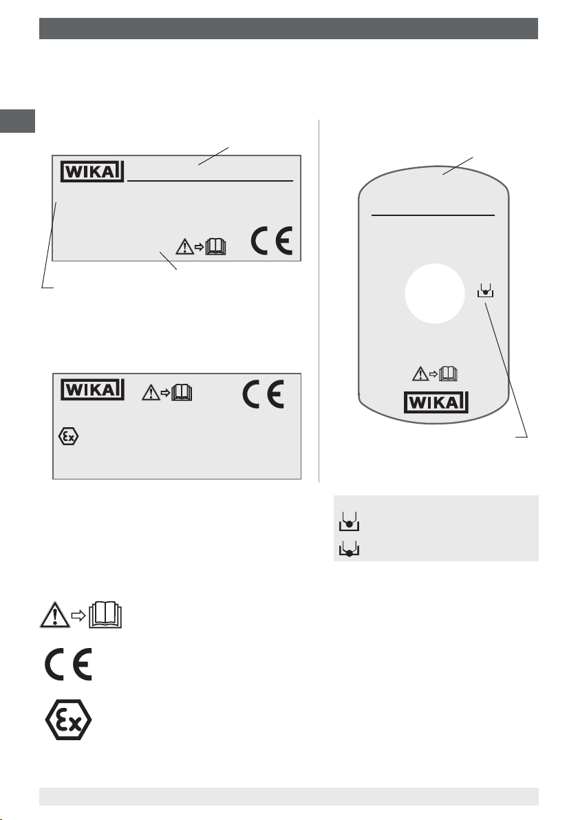
2.4 Labelling, safety marking
Product label (example)
GB
■
Thermometer, models TR10-L, TC10-L
TR10-L
1 x Pt100 / A / 3 (F)
T32 4 ... 20 mA
®
HART
Made in Germany 2013
Sensor in accordance with standard
■
F
Thin-lm resistor
■
W Wire-wound resistor
■
Additional information for Ex instruments
-50 ... +250 °C
Model
11012345
0 ... +100 °C
Year of manufacture
EN 60751
■
Measuring insert, models TR10-K,
TC10-K
Model
TC10-K
2013
1 x Type K / 1 / .
0 ... 600 °C
D = 6 mm
11012345
EN 60584-1
500 mm
DNV 10 ATEX 88843X
II 2 G Ex d IIC T6/T5/T4
WARNING: DO NOT OPEN WHILE ENERGIZED!
Explanation of symbols
8
CE, Communauté Européenne
Instruments bearing this mark comply with the relevant European directives.
ATEX European Explosion Protection Directive
(Atmosphère = AT, explosible = EX)
Instruments bearing this mark comply with the requirements of the European
directive 94/9/EC (ATEX) on explosion protection.
2013
Before mounting and commissioning the instrument, ensure you read the
operating instructions!
0158
Sensor in accordance with standard
Legend:
■
ungrounded
■
grounded
■
ungrounded
ungrounded welded
■
grounded
welded to the sheath (grounded)
WIKA operating instructions models TR10-L, TC10-L (Ex d)
3370964.05 04/2014 GB/D/F/E
Page 9

3. Specications
3. Specications
3.1 Resistance thermometer
Sensor connection method
■
2-wire
■
3-wire
■
4-wire
Sensor tolerance value per DIN EN 60751
■
Class B
■
Class A
■
Class AA
The combinations of a 2-wire connection with class A or class AA are not permissible, since
the lead resistance of the measuring insert negates the higher sensor accuracy.
Basic values and tolerance values
Basic values and tolerance values for the platinum measurement resistances are laid down
in DIN EN 60751.
The nominal value of Pt100 sensors is 100 Ω at 0 °C. The temperature coecient α can be
stated simply to be between 0 °C and 100 °C with:
-3
-1
α = 3.85 ∙ 10
°C
GB
The relationship between temperature and electrical resistance is described by polynomials,
which are also dened in DIN EN 60751. Moreover, this standard species the basic values
in °C steps in tabular form.
Class
B -196 … +600 °C -50 … +500 °C ±(0.30 + 0.0050 | t |)
A -100 … +450 °C -30 … +300 °C ±(0.15 + 0.0020 | t |)
AA -50 … +250 °C 0 … +150 °C ±(0.10 + 0.0017 | t |)
1) | t | is the value of the temperature in °C without consideration of the sign.
Bold: Standard version
Temperature range
Wire-wound (W) Thin-lm (F)
Tolerance value in °C
1)
1)
1)
For further specications see WIKA data sheet and the technical information sheet
IN 00.17 “Usage limitations and accuracies of platinum resistance thermometers per
EN 60751: 2008”.
3370964.05 04/2014 GB/D/F/E
WIKA operating instructions models TR10-L, TC10-L (Ex d)
9
Page 10

3. Specications
3.2 Thermocouples
3.2.1 Sensor types
Type
GB
K 1,200 °C
J 800 °C
E 800 °C
N 1,200 °C
3.2.2 Potential measurement uncertainties
Important factors which counteract the long-term stability of thermocouples.
Ageing eects/poisoning
■
Oxidation processes in thermocouples which are not appropriately protected (“bare”
thermocouple wires) result in falsications of the characteristic curves.
■
Foreign atoms (poisoning) that diuse into the original alloys lead to changes of these
original alloys and thus falsify the characteristic curve.
■
The inuence of hydrogen leads to the embrittlement of the thermocouples.
The Ni leg of the type K thermocouple is often damaged by sulphur which is contained in
exhaust gases, for example. Type J and T thermocouples age slightly, as the pure metal leg
oxidises rst.
Recommended max. operating temperature
In general, rising temperatures cause accelerated ageing eects.
Green rot
If type K thermocouples are used at temperatures from approx. 800 °C to 1,050 °C,
considerable changes of the thermoelectric voltage can occur. The cause of this is a
chromium depletion or the chrome oxidation in the NiCr leg (+ leg). The precondition
for this is a low concentration of oxygen or steam in the immediate environment of the
thermocouple. The nickel leg is not aected by it. The consequence of this eect is a drift of
the measured value caused by decreasing thermoelectric voltage. This eect is accelerated
if there is a shortage of oxygen (reducing atmosphere), since a complete oxide layer, which
would protect it from further oxidation of the chromium, cannot be formed on the surface of
the thermocouple.
The thermocouple is permanently destroyed by this process. The name green rot is derived
from the greenish shimmering colouration on the breaking point of the wire.
The thermocouple type N has in this regard an advantage due to its silicium content. Here, a
protective oxide layer forms on its surface under the same conditions.
10
WIKA operating instructions models TR10-L, TC10-L (Ex d)
3370964.05 04/2014 GB/D/F/E
Page 11

3. Specications
K eect
The NiCr leg of a type K thermocouple has an ordered alignment with respect to the
alignment in the crystal lattice below approx. 400 °C. If the thermocouple is heated further, a
transition to a disordered state occurs in the temperature range between approx. 400 °C and
600 °C. Above 600 °C, an ordered crystal lattice is restored.
If these thermocouples cool too quickly (quicker than approx. 100 °C per hour), the
undesirable disordered crystal lattice occurs again during cooling in the range from
approx. 600 °C to approx. 400 °C. In the characteristic curve of type K, however, a
consistently ordered alignment state is assumed and provided with values. This results in
a fault of thermoelectric voltage of up to approx. 0.8 mV (approx. 5 °C) in this range. The K
eect is reversible and is largely eliminated again by annealing above 700 °C, followed by
correspondingly slow cooling.
Thin sheathed thermocouples are particularly sensitive in this regard. Cooling in resting air
can already lead to deviations of 1 °C.
In type N thermocouples, it has been possible to reduce this short-range-order eect by
alloying both legs with silicium.
The application range of these thermometers is limited both by the permissible maximum
temperature of the thermocouple and by the max. temperature of the thermowell material.
Listed models are available both as single or dual thermocouples. The thermocouple will be
delivered with an insulated measuring point, unless explicitly specied otherwise.
GB
Tolerance value
For the tolerance value of thermocouples, a cold junction temperature of 0 °C has been
taken as the basis. When using a compensating cable or thermocouple cable, an additional
measuring deviation must be considered.
For tolerance values and further specications, see the corresponding WIKA data sheet and
technical information sheet IN 00.23, “Application of thermocouples”.
For further specications see WIKA data sheet TE 60.12, TE 65.12 and the order
documentation.
For further important safety instructions for operation in hazardous areas, see
chapter 7 “Information on mounting and operation in hazardous areas”.
3370964.05 04/2014 GB/D/F/E
WIKA operating instructions models TR10-L, TC10-L (Ex d)
11
Page 12

4. Design and function
4. Design and function
4.1 Description
The model TR10-L (resistance thermometer) or TC10-L (thermocouple) electrical
GB
thermometers are comprised of a measuring insert which is built into a certied Ex d
housing. In combination with a ame path tting that is screwed into the head, the measuring
insert functions as a ameproof joint. The measuring insert (TR10-K, TC10-K) is replaceable.
Sensor design in model TR10-L
The measuring resistor is embedded in ceramic powder, heat-resistant potting compound,
cement compound or thermally conductive paste. A one-sided sealed tube, which is welded
to a mineral-insulated cable, forms the external shell of the sensor tip of the measuring
insert.
Sensor design in model TC10-L
The measuring insert of the thermocouple is manufactured from mineral-insulated cable.
The thermocouple consists of the internal leads of the mineral-insulated cable. The weld
spot of the thermocouple is, depending on the design, either ungrounded welded with the
sheath of the mineral-insulated cable or grounded welded.
If the temperature sensor is designed as a grounded thermocouple, the thermocouple is
joined directly to the sheath. Designs with a diameter smaller than 3 mm and with grounded
thermocouples should be considered as galvanically connected with earth potential.
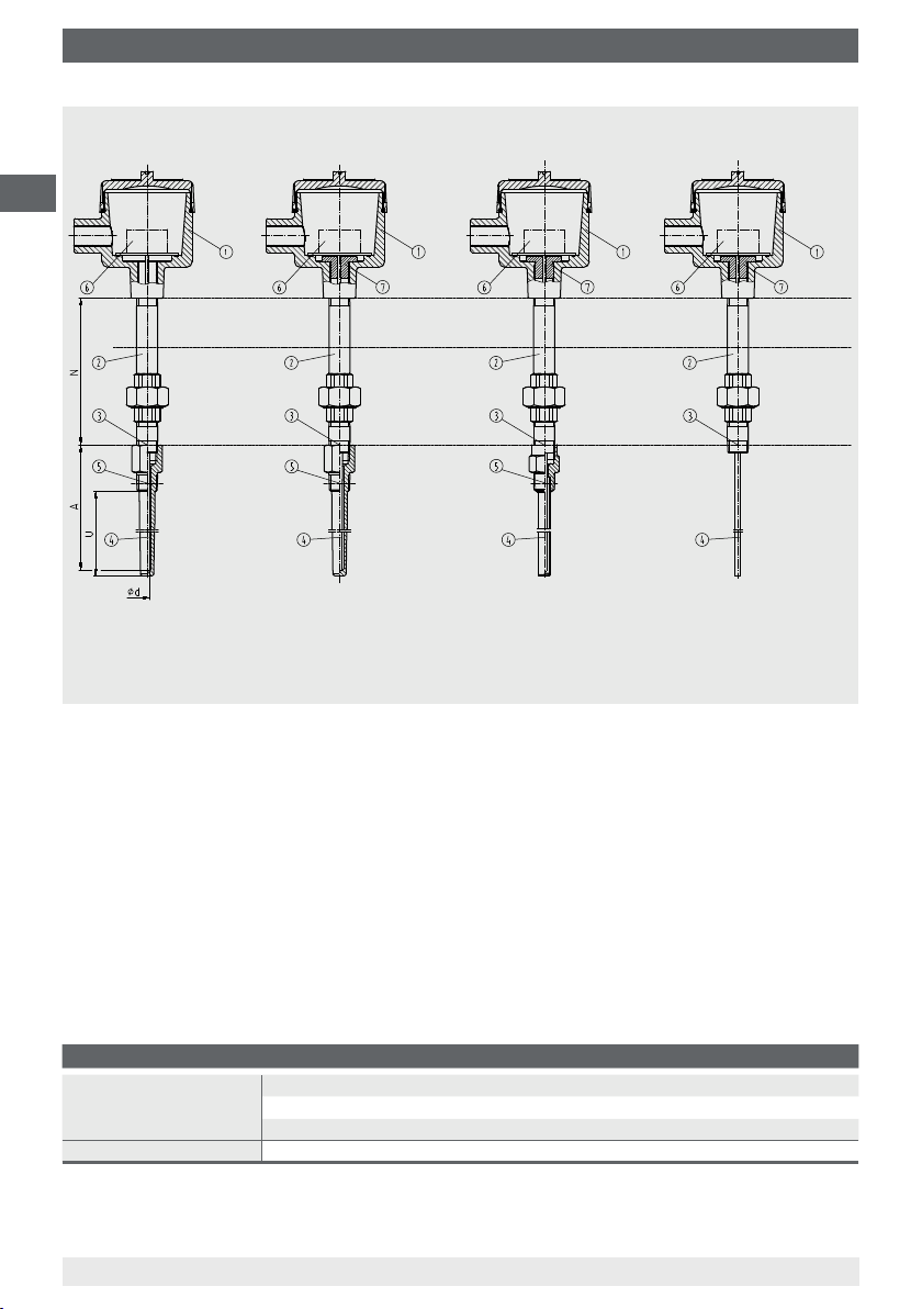
Versions (see gures page 18):
■
Thermometers without a ame path tting may only be used in combination with a
solid-machined, certied WIKA thermowell with a minimal wall thickness of 1 mm. The
thermometer is marked with IIC and is suitable for use in zone 1.
■
After installation of a ame path tting into the connection head of the thermometer, a
thermowell is no longer mandatory for certication reasons. In most cases, however,
the use of a thermowell (solid-machined or fabricated, with a wall thickness of 1 mm) is
necessary for process engineering reasons. The thermometer is marked with IIB + H
is suitable for use in zone 1.
The design of the thermowell can be selected as desired, but the operational process
data (temperature, pressure, density and ow rate) must be taken into account. If a solid
WIKA thermowell is already available or installed, a ame path tting is not necessary.
The thermometers models TR10-L or TC10-L are manufactured by WIKA with certied
Ex d connection heads or connection housings. These enclosures and covers are made
from aluminium or stainless steel. The cover is optionally available with a glass window.
12
WIKA operating instructions models TR10-L, TC10-L (Ex d)
and
2
3370964.05 04/2014 GB/D/F/E
Page 13

4. Design and function / 5. Transport, packaging and storage
Possible sensor measuring ranges:
Model TR10-L: -200 ... +600 °C
Model TC10-L: -40 ... +1,200 °C
The following mounting and operating information has been compiled with care.
However, it is not possible to consider all potential usage cases.
4.2 Scope of delivery
Cross-check scope of delivery with delivery note.
5. Transport, packaging and storage
5.1 Transport
Check the instrument for any damage that may have been caused by transport.
Obvious damage must be reported immediately.
5.2 Packaging
Do not remove packaging until just before mounting. Keep the packaging as it will provide
optimum protection during transport (e.g. change in installation site, sending for repair).
5.3 Storage
Permissible conditions at the place of storage:
■
Storage temperature:
Instruments without built-in transmitter: -50 ... +85 °C
Instruments with built-in transmitter: see operating instructions of the corresponding
transmitter
■
Humidity: 35 ... 85 % relative humidity (no condensation)
GB
Avoid exposure to the following factors:
■
Direct sunlight or proximity to hot objects
■
Mechanical vibration, mechanical shock (putting it down hard)
■
Soot, vapour, dust and corrosive gases
Store the instrument in its original packaging in a location that fulls the conditions listed
above. If the original packaging is not available, pack and store the instrument as described
below:
1. Wrap the instrument in an antistatic plastic lm.
2. Place the instrument along with shock-absorbent material in the packaging.
3. If stored for a prolonged period of time (more than 30 days), place a bag containing a
desiccant inside the packaging.
3370964.05 04/2014 GB/D/F/E
WIKA operating instructions models TR10-L, TC10-L (Ex d)
13
Page 14

6. Commissioning, operation
WARNING!
Before storing the instrument (following operation), remove any residual media.
This is of particular importance if the medium is hazardous to health, e.g. caustic,
GB
6. Commissioning, operation
6.1 Removal and installation of the measuring insert
When servicing is necessary, the ame path tting must be renewed when replacing the
measuring insert. When recalibrating, make sure that both surfaces of the ameproof joint
(ame path tting and measuring insert) are not damaged when removing the measuring
insert.
6.2 Electrical connection
Connection to terminal block
For the electrical specications (e.g. connection diagrams, tolerance values, etc.) please
refer to the data sheets TE 60.12 (for TR10-L) and TE 65.12 (for TC10-L).
Connection to built-in transmitter
For the electrical specications (e.g. connection diagrams, tolerance values, etc.) please
refer to the relevant operating instructions and/or data sheet for the built-in head-mounted
transmitter.
toxic, carcinogenic, radioactive, etc.
■
Junction between Ex d cable gland and connection head
Threads M20 x 1.5: tightening torques 12 Nm
Threads ½ NPT: tightening torques 30 Nm
■
Junction between cable and Ex d cable gland
Screw the male nut tightly into the adapter (use appropriate tools!)
During installation, take care to
■
Avoid distorting the cable sheath when tightening the male nut.
■
Avoid cutting too deep into the cable sheath.
■
Use suitable cable.
■
Be careful of the clamping zone of the cable gland.
14
WIKA operating instructions models TR10-L, TC10-L (Ex d)
3370964.05 04/2014 GB/D/F/E
Page 15
6. Commissioning, operation
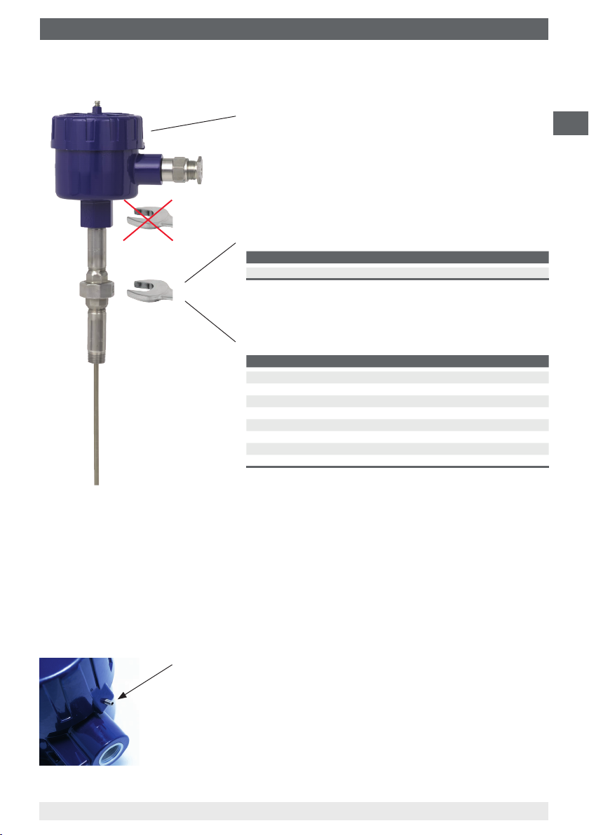
6.3 Tightening torques
Connection head, selectable (example)
Tightening torques for connection to neck tube
Thread Tightening torques in Nm
1)
R 1/2
1) only for versions with “nipple-union-nipple” neck tube
Tightening torques for connection to thermowell
Thread
1/2 NPT 35
3/4 NPT 40
G 1/2 B 35
G 3/4 B 40
M14 x 1.5 25 ... 30
M18 x 1.5 35
M20 x 1.5 35 ... 40
M27 x 2 40 ... 45
■
Only ever screw in, or unscrew, the instrument via the spanner-ats and to the prescribed
50 ... 60
Tightening torques in Nm
torque using an appropriate tool.
■
The correct torque depends on the dimensions of the connection thread and the gasket
used (form/material).
■
Screwing or unscrewing the connection head is not permitted.
■
When screwing in the instrument, please observe that the threads are not skewed.
GB
6.4 Locking screw
Always tighten the locking screw to prevent unintended opening of
the head with ameproof enclosure.
Before opening the head, always loosen the locking screw
suciently.
3370964.05 04/2014 GB/D/F/E
WIKA operating instructions models TR10-L, TC10-L (Ex d)
15
Page 16
7. Information on mounting and operation in hazardous areas
7. Information on mounting and operation in hazardous areas
GB
WARNING!
Non-observance of these instructions and their contents may result in the loss of
explosion protection.
The requirements of the 94/9/EC (ATEX) directive must be followed. Additionally
the specications of the respective national regulations concerning Ex usage
(e.g. EN/IEC 60079-10 and EN/IEC 60079-14) apply.
■
The responsibility for classication of zones lies with the plant operator and not the
manufacturer/supplier of the equipment.
■
The plant operator guarantees, and is solely responsible, that all thermometers in use are
identiable with respect to all safety-relevant characteristics. Damaged thermometers may
not be used.
■
For the installation of the thermometer, only components (e.g. cables, cable glands, etc.)
permitted for “ameproof” may be used.
■
For earthing the conductive screen, follow the specications of EN/IEC 60079-14.
■
When using a transmitter/digital display, note and follow:
- The contents of these operating instructions and those of the transmitter/digital display
- The relevant regulations for installation and use of electrical systems
- The regulation and guidelines regarding explosion protection
■
The ameproof thermometers should only be tted to certied housing- or connection
heads certied with a “ameproof” ignition protection type.
■
For tting, the permitted ameproof joints for electrical equipment for gas hazardous
areas are contained in EN, IEC 60079-1. Flameproof joints
1)
for parallel threads 2), must
be ≥ 5 mm for housing volumes < 100 cm³ and ≥ 8 mm for housing volumes > 100 cm³.
There must be ≥ 5 threads engaged.
1)
Flameprooof joints
for tapered threads 2), must have ≥ 5 available threads on each part.
There must be ≥ 3.5 threads engaged. These specications for ameproof joints must be
adhered to, without fail, when tting and during operation.
■
The direct threaded connection of the thermometer to the connection head or housing
must not be twisted or opened. Any alignment of the housing may only be made using the
optional “nipple-union-nipple” neck tube.
■
The temperature resistance of the connecting cable must match the permissible operating
temperature of the housings.
For ambient temperatures above 60 °C, heat-resistant connecting cable must be used.
■
No batteries may be built in to the ameproof housing.
1) Section 5.3 of IEC 60079-1
2) In accordance with table 3 of IEC 60079-1
16
3370964.05 04/2014 GB/D/F/E
WIKA operating instructions models TR10-L, TC10-L (Ex d)
Page 17

7. Information on mounting ... / 8. Safety-related instructions
■
No capacitor may be tted within the ameproof enclosure that has a residual energy of
≥ 0.02 mJ at the end of the time required to open the housing. The housing must not be
opened during operation. After the power supply has been switched o, a waiting time of
2 minutes must be observed before the housing is opened.
■
Mounting within metallic enclosures:
The housing must be grounded against electromagnetic elds and electrostatic
discharge. It does not have to be connected separately to the equipotential bonding
system. It is sucient if the metallic thermowell has a solid and secured contact with the
metallic vessel or its structural components or pipelines, so long as these components are
connected to the equipotential bonding system.
■
Mounting within non-metallic enclosures:
All electrically-conductive thermometer components within the hazardous area must be
provided with equipotential bonding.
■
Neither repairs nor structural modications are permitted, and any would void the
guarantee and the respective certication.
■
The manufacturer shall not be responsible for constructional modications after delivery
of the instruments.
8. Safety-related instructions
GB
Marking
Design Flame path
tting
Solid-machined thermowell
(minimum wall thickness 1 mm)
Solid-machined thermowell
(minimum wall thickness 1 mm)
Fabricated thermowell
(minimum wall thickness 1 mm)
Without thermowell Yes II 2G Ex d IIB + H
No
Yes
Yes II 2G Ex d IIB + H2 T4/T5/T6 II 2D Ex tD A21 IP66 T85 °C
ATEX
Gas Dust
II 2G Ex d IIC T4/T5/T6
II 2G Ex d IIC T4/T5/T6
Performance information
■
with terminal block: Um = DC 2 V Im = 5 mA
■
with transmitter: Um = DC 30 V Pm = 2 W
3370964.05 04/2014 GB/D/F/E
WIKA operating instructions models TR10-L, TC10-L (Ex d)
T4/T5/T6 -
2
II 2D Ex tD A21 IP66 T85 °C
II 2D Ex tD A21 IP66 T85 °C
17
Page 18
8. Safety-related instructions
GB
Solid-machined thermowell
(minimum wall thickness 1 mm)
Legend:
Connection head
Neck tube
Connection to thermowell
Measuring insert
Process connection
Terminal block/transmitter
Flame path tting
Protection tube
(minimum wall thickness 1 mm)
U Insertion length
NL Nominal length
) Neck length
N(M
H
Without
thermowell
T
undened
T4
T3
T1
Temperature class classication, ambient temperatures
A heating in the connection head can occur with built-in transmitter through faulty
electronics. The permissible ambient temperatures depend on the housings used and any
additionally-tted head-mounted transmitter.
For all WIKA connection heads with built-in WIKA temperature transmitters, the
following interrelation is valid:
The temperature increase on the surface of the connection head or housing is less than
25 K if the following conditions are observed: power supply U
maximum DC 30 V when the
B
transmitter is operated in a current limit of 22.5 mA.
This yields the following temperature class classication:
Atmosphere Temperature class Limits for ambient temperature
Gas atmosphere T6 -50 ... +60 °C
Dust atmosphere T85 °C -50 ... +60 °C
T5 -50 ... +75 °C
T4 -50 ... +85 °C
The temperature class is dependent upon the user application and the ambient temperature.
18
WIKA operating instructions models TR10-L, TC10-L (Ex d)
3370964.05 04/2014 GB/D/F/E
Page 19
8. Safety-related instructions / 9. Maintenance and cleaning
The permissible ambient temperatures for third-party products can be seen from the relevant
approvals and/or data sheets. However, an impermissible heat reux from the process which
can exceed the operating temperature of the housing or the temperature class, must be
prevented through suitable heat insulation or a suitably long neck tube.
9. Maintenance and cleaning
9.1 Maintenance
The thermometers described here are maintenance-free.
Repairs must only be carried out by the manufacturer.
9.2 Cleaning
CAUTION!
■
Prior to cleaning the electrical connections, disconnect them properly.
■
Clean the instrument with a moist cloth.
■
Electrical connections must not come into contact with moisture.
■
Wash or clean the dismounted instrument before returning it, in order to
protect persons and the environment from exposure to residual media.
■
Residual media in the dismounted instrument can result in a risk to persons,
the environment and equipment. Take sucient precautionary measures.
GB
For information on returning the instrument see chapter 11.2 “Return”.
9.3 Calibration, recalibration
It is recommended that the measuring insert is recalibrated at regular intervals (resistance
thermometers: approx. 24 months, thermocouples: approx. 12 months). This period can
reduce, depending on the particular application. The calibration can be carried out by the
manufacturer, as well as on site by qualied technical sta with calibration instruments.
3370964.05 04/2014 GB/D/F/E
WIKA operating instructions models TR10-L, TC10-L (Ex d)
19
Page 20
10. Faults
10. Faults
Faults Causes Measures
GB
No signal/
line break
Erroneous measured
values
Erroneous measured
values (too low)
Erroneous measured
values and response
times too long
Erroneous measured
values (of thermocouples)
Indication of the
measured value jumps
Corrosion
Signal interference
Mechanical load too high or
overtemperature
Sensor drift caused by
overtemperature
Sensor drift caused by chemical attack
Entry of moisture into cable or
measuring insert
Wrong mounting geometry, for example
mounting depth too deep or heat
dissipation too high
Deposits on the sensor or thermowell
Parasitic voltages (thermal voltages,
galvanic voltage) or wrong equalisation
line
Cable break in connecting cable or
loose contact caused by mechanical
overload
Composition of the medium not
as expected or modied or wrong
thermowell material selected
Stray currents caused by electric elds
or earth loops
Earth loops Elimination of potentials, use of
Replacement of the sensor or the
measuring insert with a suitable version
Replacement of the sensor or the
measuring insert with a suitable version
Use of a suitable thermowell
Replacement of the sensor or the
measuring insert with a suitable version
The temperature-sensitive area of the
sensor must be inside the medium, and
surfaces must be ungrounded
Remove deposits
Check polarity
Use of a suitable equalisation line
Replacement of the sensor or measuring
insert with a suitable design, for example
tted with strain relief or a thicker
conductor cross-section
Analyse medium and then select a
more-suitable material or replace
thermowell regularly
Use of screened connecting cables,
increase in the distance to motors and
power lines
galvanically isolated transmitter supply
isolators or transmitters
20
CAUTION!
If faults cannot be eliminated by means of the measures listed above, the
instrument must be shut down immediately, and it must be ensured that signal
is no longer present, and it must be prevented from being inadvertently put back
into service. In this case, contact the manufacturer.
If a return is needed, follow the instructions given in chapter 11.2 “Return”.
3370964.05 04/2014 GB/D/F/E
WIKA operating instructions models TR10-L, TC10-L (Ex d)
Page 21
11. Dismounting, return and disposal
11. Dismounting, return and disposal
WARNING!
Residual media in dismounted instruments can result in a risk to persons, the
environment and equipment. Take sucient precautionary measures.
11.1 Dismounting
WARNING!
Risk of burns!
Let the instrument cool down suciently before dismounting it! During
dismounting there is a risk of dangerously hot pressure media escaping.
Only disconnect the thermometer once the system has been depressurised!
11.2 Return
WARNING!
Strictly observe the following when shipping the instrument:
All instruments delivered to WIKA must be free from any kind of hazardous
substances (acids, bases, solutions, etc.).
When returning the instrument, use the original packaging or a suitable transport package.
GB
To avoid damage:
1. Wrap the instrument in an antistatic plastic lm.
2. Place the instrument along with shock-absorbent material in the packaging.
Place shock-absorbent material evenly on all sides of the transport packaging.
3. If possible, place a bag containing a desiccant inside the packaging.
4. Label the shipment as carriage of a highly sensitive measuring instrument.
Information on returns can be found under the heading “Service” on our local
website.
11.3 Disposal
Incorrect disposal can put the environment at risk.
Dispose of instrument components and packaging materials in an environmentally
compatible way and in accordance with the country-specic waste disposal regulations.
3370964.05 04/2014 GB/D/F/E
WIKA operating instructions models TR10-L, TC10-L (Ex d)
21
Page 22
Appendix: EC declaration of conformity
GB
22
3370964.05 04/2014 GB/D/F/E
WIKA operating instructions models TR10-L, TC10-L (Ex d)
Page 23
Inhalt
Inhalt
1. Allgemeines 24
2. Sicherheit 25
3. Technische Daten 29
4. Aufbau und Funktion 32
5. Transport, Verpackung und Lagerung 33
6. Inbetriebnahme, Betrieb 34
Hinweise zu Montage und Betrieb im explosions-
7.
gefährdeten Bereich (Europa)
8. Sicherheitstechnische Hinweise 37
9. Wartung und Reinigung
10. Störungen 40
11. Demontage, Rücksendung und Entsorgung 41
Anlage: EG-Konformitätserklärung 42
Konformitätserklärungen nden Sie online unter www.wika.de.
36
39
D
3370964.05 04/2014 GB/D/F/E
WIKA Betriebsanleitung Typen TR10-L, TC10-L (Ex d)
23
Page 24

1. Allgemeines
1. Allgemeines
■
Das in der Betriebsanleitung beschriebene Gerät wird nach dem aktuellen Stand der
Technik gefertigt. Alle Komponenten unterliegen während der Fertigung strengen
Qualitäts- und Umweltkriterien. Unsere Managementsysteme sind nach ISO 9001 und
ISO 14001 zertiziert.
D
■
Diese Betriebsanleitung gibt wichtige Hinweise zum Umgang mit dem Gerät.
Voraussetzung für sicheres Arbeiten ist die Einhaltung aller angegebenen
Sicherheitshinweise und Handlungsanweisungen.
■
Die für den Einsatzbereich des Gerätes geltenden örtlichen Unfallverhütungsvorschriften
und allgemeinen Sicherheitsbestimmungen einhalten.
■
Die Betriebsanleitung ist Produktbestandteil und muss in unmittelbarer Nähe des Gerätes
für das Fachpersonal jederzeit zugänglich aufbewahrt werden.
■
Das Fachpersonal muss die Betriebsanleitung vor Beginn aller Arbeiten sorgfältig durchgelesen und verstanden haben.
■
Die Haftung des Herstellers erlischt bei Schäden durch bestimmungswidrige Verwen-
dung, Nichtbeachten dieser Betriebsanleitung, Einsatz ungenügend qualizierten
Fachpersonals sowie eigenmächtiger Veränderung am Gerät.
■
Es gelten die allgemeinen Geschäftsbedingungen in den Verkaufsunterlagen.
■
Technische Änderungen vorbehalten.
■
Weitere Informationen:
- Internet-Adresse: www.wika.de / www.wika.com
- zugehöriges Datenblatt: TE 60.12 (TR10-L), TE 65.12 (TC10-L)
- Anwendungsberater:
Tel.: +49 9372 132-0
Fax: +49 9372 132-406
info@wika.de
Symbolerklärung
WARNUNG!
… weist auf eine möglicherweise gefährliche Situation hin, die zum Tod oder zu
schweren Verletzungen führen kann, wenn sie nicht gemieden wird.
VORSICHT!
… weist auf eine möglicherweise gefährliche Situation hin, die zu geringfügigen
oder leichten Verletzungen bzw. Sach- und Umweltschäden führen kann, wenn
sie nicht gemieden wird.
24
WIKA Betriebsanleitung Typen TR10-L, TC10-L (Ex d)
3370964.05 04/2014 GB/D/F/E
Page 25
1. Allgemeines / 2. Sicherheit
Information
… hebt nützliche Tipps und Empfehlungen sowie Informationen für einen ezienten und störungsfreien Betrieb hervor.
WARNUNG!
… weist auf eine möglicherweise gefährliche Situation im explosionsgefährdeten
Bereich hin, die zum Tod oder zu schweren Verletzungen führen kann, wenn sie
nicht gemieden wird.
WARNUNG!
… weist auf eine möglicherweise gefährliche Situation hin, die durch heiße
Oberächen oder Flüssigkeiten zu Verbrennungen führen kann, wenn sie nicht
gemieden wird.
2. Sicherheit
WARNUNG!
Vor Montage, Inbetriebnahme und Betrieb sicherstellen, dass das richtige
Thermometer hinsichtlich Messbereich, Ausführung und spezischen Messbedingungen ausgewählt wurde.
D
Schutzrohr hinsichtlich Maximaldruck und -temperatur (z. B. Belastungsdiagramme in DIN 43772) auswählen.
Bei Nichtbeachten können schwere Körperverletzungen und/oder Sachschäden
auftreten.
Weitere wichtige Sicherheitshinweise benden sich in den einzelnen Kapiteln
dieser Betriebsanleitung.
2.1 Bestimmungsgemäße Verwendung
Diese Widerstandsthermometer und Thermoelemente dienen zur Temperaturmessung in
industriellen Anwendungen, in explosionsgefährdeten Bereichen.
Das Gerät ist ausschließlich für den hier beschriebenen bestimmungsgemäßen
Verwendungszweck konzipiert und konstruiert und darf nur dementsprechend verwendet
werden.
Die technischen Spezikationen in dieser Betriebsanleitung sind einzuhalten. Eine
unsachgemäße Handhabung oder ein Betreiben des Gerätes außerhalb der technischen
Spezikationen macht die sofortige Stilllegung und Überprüfung durch einen autorisierten
WIKA-Servicemitarbeiter erforderlich.
3370964.05 04/2014 GB/D/F/E
WIKA Betriebsanleitung Typen TR10-L, TC10-L (Ex d)
25
Page 26
2. Sicherheit
Wird das Gerät von einer kalten in eine warme Umgebung transportiert, so kann durch
Kondensatbildung eine Störung der Gerätefunktion eintreten. Vor einer erneuten
Inbetriebnahme die Angleichung der Gerätetemperatur an die Raumtemperatur abwarten.
Ansprüche jeglicher Art aufgrund von nicht bestimmungsgemäßer Verwendung sind
ausgeschlossen.
D
2.2 Personalqualikation
WARNUNG!
Verletzungsgefahr bei unzureichender Qualikation!
Unsachgemäßer Umgang kann zu erheblichen Personen- und Sachschäden
führen.
■
Die in dieser Betriebsanleitung beschriebenen Tätigkeiten nur durch Fachper-
sonal nachfolgend beschriebener Qualikation durchführen lassen.
■
Unqualiziertes Personal von den Gefahrenbereichen fernhalten.
Fachpersonal
Das Fachpersonal ist aufgrund seiner fachlichen Ausbildung, seiner Kenntnisse der Mess-
und Regelungstechnik und seiner Erfahrungen sowie Kenntnis der landesspezischen
Vorschriften, geltenden Normen und Richtlinien in der Lage, die beschriebenen Arbeiten
auszuführen und mögliche Gefahren selbstständig zu erkennen.
Spezielle Einsatzbedingungen verlangen weiteres entsprechendes Wissen, z. B. über
aggressive Medien.
2.3 Besondere Gefahren
WARNUNG!
Die Angaben der geltenden Baumusterprüfbescheinigung sowie die jeweiligen
landesspezischen Vorschriften zur Installation und Einsatz in explosionsgefährdeten Bereichen (z. B. IEC 60079-14, NEC, CEC) einhalten. Bei Nichtbeachten
können schwere Körperverletzungen und/oder Sachschäden auftreten.
Weitere wichtige Sicherheitshinweise für Geräte mit ATEX-Zulassung siehe
Kapitel 7 „Hinweise zu Montage und Betrieb im explosionsgefährdeten Bereich“.
WARNUNG!
Bei gefährlichen Messstoen wie z. B. Sauersto, Acetylen, brennbaren oder
giftigen Stoen, sowie bei Kälteanlagen, Kompressoren etc. müssen über die
gesamten allgemeinen Regeln hinaus die einschlägigen Vorschriften beachtet
werden.
26
WIKA Betriebsanleitung Typen TR10-L, TC10-L (Ex d)
3370964.05 04/2014 GB/D/F/E
Page 27

2. Sicherheit
WARNUNG!
Schutz vor elektrostatischer Entladung (ESD) erforderlich! Die ordnungsgemä-
ße Verwendung geerdeter Arbeitsächen und persönlicher Armbänder ist bei
Arbeiten mit oenen Schaltkreisen (Leiterplatten) erforderlich, um die Beschädigung empndlicher elektronischer Bauteile durch elektrostatische Entladung zu
vermeiden.
Für ein sicheres Arbeiten am Gerät muss der Betreiber sicherstellen,
■
dass eine entsprechende Erste-Hilfe-Ausrüstung vorhanden ist und bei
Bedarf jederzeit Hilfe zur Stelle ist.
■
dass das Bedienpersonal regelmäßig in allen zutreenden Fragen von
Arbeitssicherheit, Erste-Hilfe und Umweltschutz unterwiesen wird, sowie die
Betriebs-anleitung und insbesondere die darin enthaltenen Sicherheitshinweise kennt.
WARNUNG!
Messstoreste in ausgebauten Geräten können zur Gefährdung von Personen,
Umwelt und Einrichtung führen. Ausreichende Vorsichtsmaßnahmen ergreifen.
Dieses Gerät nicht in Sicherheits- oder in Not-Aus-Einrichtungen benutzen.
Fehlerhafte Anwendungen des Gerätes können zu Verletzungen führen.
Am Gerät können im Fehlerfall aggressive Medien mit extremer Temperatur und
unter hohem Druck oder Vakuum anliegen.
D
3370964.05 04/2014 GB/D/F/E
WIKA Betriebsanleitung Typen TR10-L, TC10-L (Ex d)
27
Page 28

11012345
TC10-K
EN 60584-1
1 x Type K / 1 / .
0 ... 600 °C
D = 6 mm
500 mm
2013
TR10-L
1 x Pt100 / A / 3 (F)
T32 4 ... 20 mA
-50 ... +250 °C
EN 60751
Made in Germany 2013
11012345
0 ... +100 °C
HART
®
11012345
TC10-K
EN 60584-1
1 x Type K / 1 / .
0 ... 600 °C
D = 6 mm
500 mm
2013
2. Sicherheit
2.4 Beschilderung, Sicherheitskennzeichnungen
Typenschild (Beispiel)
■
Thermometer, Typen TR10-L, TC10-L
D
TR10-L
1 x Pt100 / A / 3 (F)
T32 4 ... 20 mA
®
HART
Made in Germany 2013
Sensor gemäß Norm
■
F
Dünnlm-Messwiderstand
■
W Drahtgewickelter Messwiderstand
■
Zusätzliche Angaben für Ex-Geräte
DNV 10 ATEX 88843X
II 2 G Ex d IIC T6/T5/T4
WARNING: DO NOT OPEN WHILE ENERGIZED!
Typ
-50 ... +250 °C
0 ... +100 °C
Herstellungsjahr
2013
11012345
EN 60751
■
Messeinsatz, Typen TR10-K, TC10-K
TC10-K
0158
2013
1 x Type K / 1 / .
0 ... 600 °C
D = 6 mm
Legende:
■
ungrounded
isoliert verschweißt
■
grounded
mit dem Mantel verschweißt (geerdet)
11012345
Sensor gemäß Norm
■
ungrounded
■
grounded
Typ
EN 60584-1
500 mm
Symbolerklärung
28
Vor Montage und Inbetriebnahme des Gerätes unbedingt die Betriebsanleitung lesen!
CE, Communauté Européenne
Geräte mit dieser Kennzeichnung stimmen überein mit den zutreenden europäischen Richtlinien.
ATEX Europäische Explosionsschutz-Richtlinie
(Atmosphère = AT, explosible = EX)
Geräte mit dieser Kennzeichnung stimmen überein mit den Anforderungen der
europäischen Richtlinie 94/9/EG (ATEX) zum Explosionsschutz.
WIKA Betriebsanleitung Typen TR10-L, TC10-L (Ex d)
3370964.05 04/2014 GB/D/F/E
Page 29

3. Technische Daten
3. Technische Daten
3.1 Widerstandsthermometer
Sensor-Schaltungsart
■
2-Leiter
■
3-Leiter
■
4-Leiter
Grenzabweichung des Sensors nach DIN EN 60751
■
Klasse B
■
Klasse A
■
Klasse AA
Die Kombinationen 2-Leiter-Schaltungsart und Klasse A oder Klasse AA sind nicht zulässig,
da der Leitungswiderstand des Messeinsatzes der höheren Sensorgenauigkeit entgegen
wirkt.
Grundwerte und Grenzabweichungen
Grundwerte und Grenzabweichungen von Platin-Messwiderständen sind festgelegt in
DIN EN 60751.
Der Nennwert von Pt100 Sensoren beträgt 100 Ω bei 0 °C. Der Temperaturkoezient α kann
zwischen 0 °C und 100 °C vereinfacht angegeben werden mit:
D
-3
-1
α = 3,85 ∙ 10
°C
Der Zusammenhang zwischen der Temperatur und dem elektrischen Widerstand wird durch
Polynome beschrieben, die ebenfalls in DIN EN 60751 deniert sind. Weiterhin legt diese
Norm die Grundwerte in °C-Schritten tabellarisch fest.
Klasse
B -196 … +600 °C -50 … +500 °C ±(0,30 + 0,0050 | t |)
A -100 … +450 °C -30 … +300 °C ±(0,15 + 0,0020 | t |)
AA -50 … +250 °C 0 … +150 °C ±(0,10 + 0,0017 | t |)
1) | t | ist der Zahlenwert der Temperatur in °C ohne Berücksichtigung des Vorzeichens.
Fett gedruckt: Standardausführung
Temperaturbereich
Drahtgewickelt (W) Dünnschicht (F)
Grenzabweichung in °C
1)
1)
1)
Weitere technische Daten siehe WIKA-Datenblatt und Technische Information IN 00.17
„Einsatzgrenzen und Genauigkeiten von Platin-Widerstandsthermometern nach
EN 60751: 2008“.
3370964.05 04/2014 GB/D/F/E
WIKA Betriebsanleitung Typen TR10-L, TC10-L (Ex d)
29
Page 30

3. Technische Daten
3.2 Thermoelemente
3.2.1 Sensortypen
Ty p
K 1.200 °C
J 800 °C
E 800 °C
D
N 1.200 °C
3.2.2 Potenzielle Messunsicherheiten
Wichtige Faktoren, die der Langzeitstabilität von Thermoelementen entgegenwirken.
Alterungserscheinungen/Vergiftungen
■
Oxidationsvorgänge führen bei nicht entsprechend geschützten Thermoelementen
(„blanke“ Thermodrähte) zu Kennlinienverfälschungen.
■
Eindiundierende Fremdatome (Vergiftungen) führen zu Veränderungen der Ursprungslegierungen und damit zu Verfälschungen der Kennlinie.
■
Der Einuss von Wassersto führt zur Versprödung der Thermoelemente.
Der Ni-Schenkel des Typ K-Thermoelementes wird häug durch Schwefel, der z. B. in
Rauchgasen vorkommt, geschädigt. Thermoelemente der Typen J und T altern gering, weil
zunächst der Reinmetallschenkel oxydiert.
Empfohlene max. Betriebstemperatur
Generell nehmen die Alterungserscheinungen mit steigenden Temperaturen zu.
Grünfäule
Bei Typ K-Thermoelementen können beim Einsatz in Temperaturen von ca. 800 °C bis
1.050 °C erhebliche Veränderungen der Thermospannung auftreten. Die Ursache hierfür ist
eine Chromverarmung bzw. Oxidation des Chroms im NiCr-Schenkel (+ Schenkel). Voraus-
setzung hierfür ist eine geringe Konzentration Sauersto oder Wasserdampf in der direkten
Umgebung des Thermoelementes. Der Nickel-Schenkel ist hiervon nicht betroen. Die
Folge dieses Eekts ist eine Drift des Messwertes durch sinkende Thermospannung. Bei
Sauerstomangel (reduzierende Atmosphäre) wird dieser Eekt noch beschleunigt, da sich
keine vollständigen Oxidhäute auf der Oberäche des Thermoelementes ausbilden können,
die einer weiteren Oxidation des Chroms entgegenwirken.
Das Thermoelement wird auf Dauer durch diesen Vorgang zerstört. Der Name Grünfäule
kommt von der grünlichen schimmernden Färbung an der Bruchstelle des Drahtes.
Das Thermoelement Typ N ist bedingt durch seinen Siliziumgehalt in dieser Beziehung im
Vorteil. Hier bildet sich unter gleichen Bedingungen eine schützende Oxidschicht auf seiner
Oberäche aus.
30
WIKA Betriebsanleitung Typen TR10-L, TC10-L (Ex d)
3370964.05 04/2014 GB/D/F/E
Page 31

3. Technische Daten
K-Eekt
Der NiCr-Schenkel eines Typ K-Thermoelementes besitzt bezüglich der Ausrichtung im
Kristallgitter unterhalb ca. 400 °C eine geordnete Ausrichtung. Wird das Thermoelement
weiter erhitzt, so ndet im Temperaturbereich zwischen ca. 400 °C und 600 °C ein Übergang
in einen ungeordneten Zustand statt. Oberhalb von 600 °C stellt sich wieder ein geordnetes
Kristallgitter ein.
Bei einem zu schnellen Abkühlen dieser Thermoelemente (schneller als ca. 100 °C pro
Stunde) kommt es während der Abkühlung im Bereich von ca. 600 °C bis ca. 400 °C wieder
zum unerwünschten ungeordneten Kristallgitter. In der Kennlinie von Typ K ist aber ein
durchgängig geordneter Ausrichtungszustand vorausgesetzt und mit Werten hinterlegt. Ein
Thermospannungsfehler von bis zu ca. 0,8 mV (ca. 5 °C) in diesem Bereich ist die Folge.
Der K-Eekt ist reversibel und wird durch Glühen oberhalb 700 °C mit anschließender
entsprechend langsamer Abkühlung größtenteils wieder abgebaut.
Dünne Mantel-Thermoelemente reagieren hier besonders empndlich. Schon eine Abkühlung an ruhender Luft kann Abweichungen von 1 °C zur Folge haben.
Beim Typ N-Thermoelement hat man diesen Nahordnungseekt durch Legieren beider
Schenkel mit Silizium verringern können.
Die tatsächliche Gebrauchstemperatur des Thermometers wird begrenzt sowohl durch die
maximal zulässige Einsatztemperatur des Thermoelementes, als auch durch die maximal
zulässige Einsatztemperatur des Schutzrohrwerkstoes.
D
Gelistete Typen sind als einfaches Thermopaar oder als doppeltes Thermopaar lieferbar.
Das Thermoelement wird mit isolierter Messstelle geliefert, wenn nicht ausdrücklich anders
speziziert wurde.
Grenzabweichung
Bei der Grenzabweichung von Thermopaaren ist eine Vergleichsstellentemperatur von 0 °C
zugrunde gelegt. Bei Verwendung einer Ausgleichs- oder Thermoleitung muss eine zusätzliche Messabweichung berücksichtigt werden.
Grenzabweichungen und weitere technische Daten siehe entsprechendes WIKA-Datenblatt
und Technische Information IN 00.23 „Einsatz von Thermoelementen“.
Weitere technische Daten siehe WIKA-Datenblatt TE 60.12, TE 65.12 und Bestellunterlagen.
Weitere wichtige Sicherheitshinweise für den Betrieb in explosionsgefährdeten
Bereichen siehe Kapitel 7 „Hinweise zu Montage und Betrieb im explosionsgefährdeten Bereich“.
3370964.05 04/2014 GB/D/F/E
WIKA Betriebsanleitung Typen TR10-L, TC10-L (Ex d)
31
Page 32

4. Aufbau und Funktion
4. Aufbau und Funktion
4.1 Beschreibung
Die elektrischen Thermometer Typen TR10-L (Widerstandsthermometer) bzw. TC10-L
(Thermoelement) bestehen aus einem Messeinsatz welcher in ein Ex d zertiziertes Gehäuse angebaut ist. Der Messeinsatz wirkt in Verbindung mit einem im Kopf eingeschraubten
D
Passungsbuchse als zünddurchschlagsicherer Spalt. Der Messeinsatz (TR10-K, TC10-K) ist
auswechselbar.
Sensoraufbau in Typ TR10-L
Der Messwiderstand ist eingebettet in Keramikpulver, hitzebeständiger Vergussmasse,
Zementkitt oder Wärmeleitpaste. Ein einseitig verschlossenes Röhrchen - angeschweißt an
mineralisolierte Leitung - bildet die äußere Hülle der Fühlerspitze des Messeinsatzes.
Sensoraufbau in Typ TC10-L
Der Messeinsatz des Thermoelementes ist aus mineralisolierter Leitung gefertigt. Das
Thermopaar wird durch die Innenleiter der mineralisolierten Leitung gebildet. Der Schweißpunkt des Thermoelementes ist je nach Ausführung mit dem Außenmantel der mineralisolierten Leitung isoliert oder nicht isoliert (grounded) verschweißt.
Wenn der Temperatursensor als geerdetes Thermoelement ausgeführt ist, ist das Thermopaar direkt mit dem Mantel verbunden. Ausführungen mit Durchmesser kleiner 3 mm und
geerdete Thermoelemente sind als galvanisch mit Erdpotential verbunden zu betrachten.
Ausführungen (siehe Abbildungen Seite 38):
■
Thermometer ohne Passungsbuchse dürfen nur in Kombination mit einem einteiligen,
zugelassenen WIKA-Schutzrohr mit Mindestwandstärke 1 mm eingesetzt werden. Das
Thermometer wird mit IIC gekennzeichnet und ist geeignet für den Einsatz in Zone 1.
■
Bei Einbau einer Passungsbuchse in den Anschlusskopf des Thermometers ist ein
Schutzrohr aus Zulassungsgründen nicht zwingend notwendig. Der Einsatz eines Schutzrohres (einteilig oder mehrteilig, mit einer Mindestwandstärke von 1 mm) ist aber in den
meisten Fällen aus prozesstechnischen Gründen notwendig! Das Thermometer wird mit
IIB + H2 gekennzeichnet und ist geeignet für den Einsatz in Zone 1.
Die Bauform des Schutzrohres ist beliebig auswählbar, jedoch sind die operativen
Prozessdaten (Temperatur, Druck, Dichte und Strömungsgeschwindigkeit) zu berücksichtigen. Ist ein einteiliges WIKA-Schutzrohr bereits vorhanden bzw. bereits eingebaut, ist
eine Passungsbuchse nicht erforderlich.
Die Thermometer Typen TR10-L bzw. TC10-L sind mit Ex d-zertizierten Anschlussköpfen
bzw. Anschlussgehäusen von WIKA gefertigt. Diese Gehäuse und Deckel sind aus
Aluminium oder CrNi-Stahl hergestellt. Der Deckel ist optional mit einem Glasfenster
versehen.
32
WIKA Betriebsanleitung Typen TR10-L, TC10-L (Ex d)
3370964.05 04/2014 GB/D/F/E
Page 33

4. Aufbau und Funktion / 5. Transport, Verpackung, Lagerung
Mögliche Sensormessbereiche:
Typ TR10-L: -200 ... +600 °C
Typ TC10-L: -40 ... +1.200 °C
Die nachfolgenden Einbau- und Betriebshinweise haben wir mit Sorgfalt zusammengestellt.
Es ist jedoch nicht möglich, alle erdenklichen Anwendungsfälle zu berücksichtigen.
4.2 Lieferumfang
Lieferumfang mit dem Lieferschein abgleichen.
5. Transport, Verpackung und Lagerung
5.1 Transport
Gerät auf eventuell vorhandene Transportschäden untersuchen.
Oensichtliche Schäden unverzüglich mitteilen.
5.2 Verpackung
Verpackung erst unmittelbar vor der Montage entfernen. Die Verpackung aufbewahren,
denn diese bietet bei einem Transport einen optimalen Schutz (z. B. wechselnder Einbauort,
Reparatursendung).
5.3 Lagerung
Zulässige Bedingungen am Lagerort:
■
Lagertemperatur:
Geräte ohne eingebauten Transmitter: -50 ... +85 °C
Geräte mit eingebautem Transmitter: siehe Betriebsanleitung des entspr. Transmitters
■
Feuchtigkeit: 35 ... 85 % relative Feuchte (keine Betauung)
D
Folgende Einüsse vermeiden:
■
Direktes Sonnenlicht oder Nähe zu heißen Gegenständen
■
Mechanische Vibration, mechanischer Schock (hartes Aufstellen)
■
Ruß, Dampf, Staub und korrosive Gase
Das Gerät in der Originalverpackung an einem Ort, der die oben gelisteten Bedingungen
erfüllt, lagern. Wenn die Originalverpackung nicht vorhanden ist, dann das Gerät wie folgt
verpacken und lagern:
1. Das Gerät in eine antistatische Plastikfolie einhüllen.
2. Das Gerät mit dem Dämmmaterial in der Verpackung platzieren.
3. Bei längerer Einlagerung (mehr als 30 Tage) einen Beutel mit Trocknungsmittel der
Verpackung beilegen.
3370964.05 04/2014 GB/D/F/E
WIKA Betriebsanleitung Typen TR10-L, TC10-L (Ex d)
33
Page 34

6. Inbetriebnahme, Betrieb
WARNUNG!
Vor der Einlagerung des Gerätes (nach Betrieb) alle anhaftenden Messstoreste
entfernen. Dies ist besonders wichtig, wenn der Messsto gesundheitsgefähr-
dend ist, wie z. B. ätzend, giftig, krebserregend, radioaktiv, usw.
D
6. Inbetriebnahme, Betrieb
6.1 Aus- und Einbau des Messeinsatzes
Im Servicefall muss beim Austausch des Messeinsatzes auch die Passungsbuchse erneu-
ert werden. Bei einer Nachkalibrierung darauf achten, dass die beiden Oberächen des
zünddurchschlagsicheren Spaltes (Passungsbuchse und Messeinsatz) beim Entnehmen
des Messeinsatzes nicht beschädigt werden.
6.2 Elektrischer Anschluss
Anschluss an Klemmsockel
Die elektrischen Daten (z. B. Anschlussschaltbilder, Grenzabweichungen etc.) dem Datenblatt TE 60.12 (für TR10-L) und TE 65.12 (für TC10-L) entnehmen.
Anschluss an eingebauten Transmitter
Die elektrischen Daten (z. B. Anschlussschaltbilder, Grenzabweichungen etc.) der jeweiligen
Betriebsanleitung bzw. dem jeweiligen Datenblatt des eingebauten Kopftransmitters entnehmen.
■
Verbindung zwischen Ex d-Kabelverschraubung und Anschlusskopf
Gewinde M20 x 1,5: Anzugsdrehmomente 12 Nm
Gewinde ½ NPT: Anzugsdrehmomente 30 Nm
■
Verbindung zwischen Kabel und Ex d-Kabelverschraubung
Die Druckschraube fest in das Zwischenstück einschrauben (geeignete Werkzeuge
verwenden!)
Bei der Montage beachten
■
Wegießen des Kabelmantels bei fest angezogener Druckschraube vermeiden.
■
Übermäßig tiefe Einschneidungen im Kabelmantel vermeiden.
■
Geeignete Kabel verwenden.
■
Klemmbereich der Kabelverschraubung beachten.
34
WIKA Betriebsanleitung Typen TR10-L, TC10-L (Ex d)
3370964.05 04/2014 GB/D/F/E
Page 35

6. Inbetriebnahme, Betrieb
6.3 Anzugsdrehmomente
Anschlusskopf, wählbar (Beispiel)
Anzugsdrehmomente für Anschluss zum Halsrohr
Gewinde Anzugsdrehmomente in Nm
1)
R 1/2
1) nur bei Ausführungen mit teilbarem Halsrohr
Anzugsdrehmomente für Anschluss zum Schutzrohr
Gewinde
1/2 NPT 35
3/4 NPT 40
G 1/2 B 35
G 3/4 B 40
M14 x 1,5 25 ... 30
M18 x 1,5 35
M20 x 1,5 35 ... 40
M27 x 2 40 ... 45
50 ... 60
Anzugsdrehmomente in Nm
D
■
Das Gerät nur über die Schlüsselächen mit einem geeigneten Werkzeug und dem vorge-
schriebenen Drehmoment ein- bzw. ausschrauben.
■
Das richtige Drehmoment ist abhängig von der Dimension des Anschlussgewindes sowie
der verwendeten Dichtung (Form/Werksto).
■
Das Ein- bzw. Ausschrauben des Anschlusskopfes ist nicht zulässig.
■
Beim Einschrauben beachten, dass die Gewindegänge nicht verkantet werden.
6.4 Sicherungsschraube
Sicherungsschraube stets festziehen, um unbeabsichtigtes Önen
des druckfest gekapselten Kopfes zu verhindern.
Vor dem Önen des Kopfes die Sicherungsschraube unbedingt
weit genug lösen.
3370964.05 04/2014 GB/D/F/E
WIKA Betriebsanleitung Typen TR10-L, TC10-L (Ex d)
35
Page 36

7. Hinweise zu Montage und Betrieb im Ex-Bereich
7. Hinweise zu Montage und Betrieb im explosionsgefährdeten
Bereich
WARNUNG!
Die Nichtbeachtung dieser Inhalte und Anweisungen kann zum Verlust des
D
■
Die Verantwortung über die Zoneneinteilung unterliegt dem Anlagenbetreiber und nicht
dem Hersteller/Lieferanten der Betriebsmittel.
■
Der Betreiber der Anlage stellt in eigener Verantwortung sicher, dass vollständige und im
Einsatz bendliche Thermometer bezüglich aller sicherheitsrelevanten Merkmale identizierbar sind. Beschädigte Thermometer dürfen nicht verwendet werden.
■
Bei der Installation der Thermometer, sind nur Bauteile (z. B. Leitungen, Kabelverschraubungen etc.) zulässig, die für druckfeste Kapselung geeignet sind.
■
Für die Erdung leitender Schirme die Bedingungen nach EN/IEC 60079-14 beachten.
■
Beim Einsatz eines Transmitters/Digitalanzeige beachten:
- Der Inhalt dieser und der zum Transmitter/Digitalanzeige gehörenden Betriebsanleitung
- Die einschlägigen Bestimmungen für Errichtung und Betrieb elektrischer Anlagen
- Die Verordnung und Richtlinien für den Explosionsschutz
■
Die druckfest bescheinigten Thermometer dürfen nur an bescheinigte Gehäuse- oder
Anschlussköpfe der Zündschutzart druckfeste Kapselung angebaut werden.
■
Die für die Montage zulässigen Gewindespalte für elektrische Betriebsmittel
für gasexplosionsgefährdete Bereiche sind in der EN/IEC 60079-1 enthalten.
Gewindespalte
≥ 5 mm und bei Gehäusevolumen > 100 cm³ ≥ 8 mm betragen. Es müssen sich
≥ 5 Gewindegänge im Eingri benden.
Gewindespalte
gänge haben. Es müssen sich ≥ 3,5 Gewindegänge im Eingri benden. Diese Angaben
der Gewindespalte müssen bei der Montage und im Betrieb zwingend eingehalten
werden.
■
Die direkte Schraubverbindung des Thermometers zum Anschlusskopf oder Gehäuse
darf nicht verdreht oder geönet werden. Eine Ausrichtung des Gehäuses kann nur über
das optional teilbare Halsrohr erfolgen.
■
Die Temperaturbeständigkeit der Anschlussleitung muss dem zulässigen Betriebstemperaturbereich der Gehäuse entsprechen.
Bei Umgebungstemperaturen über 60 °C sind wärmebeständige Anschlussleitungen zu
verwenden.
1) Abschnitt 5.3 der IEC 60079-1
2) Nach Tabelle 3 der IEC 60079-1
36
Explosionsschutzes führen.
Die Anforderungen der Richtlinie 94/9/EG (ATEX) müssen beachtet werden.
Zusätzlich gelten die Angaben der jeweiligen Landesvorschriften bezüglich
Ex-Einsatz (z. B. EN/IEC 60079-10 und EN/IEC 60079-14).
1)
zylindrischer Gewinde 2), müssen bei Gehäusevolumen < 100 cm³
1)
konischer Gewinde 2), müssen an jedem Teil ≥ 5 vorhandene Gewinde-
WIKA Betriebsanleitung Typen TR10-L, TC10-L (Ex d)
3370964.05 04/2014 GB/D/F/E
Page 37

7. Hinweise zu Montage ... / 8. Sicherheitstechnische Hinweise
■
Es dürfen keine Batterien bzw. Zellen in das druckfeste Gehäuse eingebaut werden.
■
Es dürfen keine Kondensatoren in das druckfeste Gehäuse eingebaut werden, die eine
verbleibende Energie von ≥ 0,02 mJ nach der Zeit aufweisen, die zum Önen des Gehäuses notwendig ist. Während des Betriebes darf das Gehäuse nicht geönet werden. Nach
dem Abschalten der Betriebsspannung eine Wartezeit von 2 Minuten vor dem Önen des
Gehäuses einhalten.
■
Montage in metallischen Behälter:
Das Gehäuse muss gegen elektromagnetische Felder und elektrostatische Auadung
geerdet werden. Es muss nicht gesondert an das Potentialausgleichsystem angeschlossen werden. Es ist ausreichend, wenn das metallische Schutzrohr festen und gesicherten
Kontakt mit dem metallischen Behälter oder dessen Konstruktionsteilen oder Rohrleitungen hat, insofern diese Bauteile mit einem Potentialausgleichsystem verbunden sind.
■
Montage in nichtmetallische Behälter:
Alle in den explosionsgefährdeten Bereich ragenden elektrisch leitenden Thermometerkomponenten müssen mit einem Potentialausgleich versehen werden.
■
Reparaturen sowie bauliche Veränderungen sind nicht zulässig und führen zur Erlöschung
der Garantie und der jeweiligen Zulassung.
■
Bauliche Veränderungen nach Auslieferung der Geräte obliegen nicht in der Verantwortung des Herstellers.
D
8. Sicherheitstechnische Hinweise
Kennzeichnung
Ausführung Passungs-
buchse
Einteiliges Schutzrohr
(Mindestwandstärke 1 mm)
Einteiliges Schutzrohr
(Mindestwandstärke 1 mm)
Mehrteiliges Schutzrohr
(Mindestwandstärke 1 mm)
Ohne Schutzrohr ja II 2G Ex d IIB + H
nein
ja
ja II 2G Ex d IIB + H2 T4/T5/T6 II 2D Ex tD A21 IP66 T85 °C
Leistungsangaben
■
mit Klemmsockel: Um = DC 2 V Im = 5 mA
■
mit Transmitter: Um = DC 30 V Pm = 2 W
3370964.05 04/2014 GB/D/F/E
WIKA Betriebsanleitung Typen TR10-L, TC10-L (Ex d)
ATEX
Gas Staub
II 2G Ex d IIC T4/T5/T6
II 2G Ex d IIC T4/T5/T6
T4/T5/T6 -
2
II 2D Ex tD A21 IP66 T85 °C
II 2D Ex tD A21 IP66 T85 °C
37
Page 38

8. Sicherheitstechnische Hinweise
D
Einteiliges Schutzrohr
(Mindestwandstärke 1 mm)
Legende:
Anschlusskopf
Halsrohr
Anschluss zum Schutzrohr
Messeinsatz
(Mindestwandstärke 1 mm)
Prozessanschluss
Klemmsockel/Transmitter
Passungsbuchse
Mehrteiliges Schutzrohr
U Einbaulänge
NL Nennlänge
) Halslänge
N(M
H
Ohne
Schutzrohr
T
unbestimmt
T4
T3
T1
Temperaturklasseneinteilung, Umgebungstemperaturen
Eine Erwärmung im Anschlusskopf kann bei eingebautem Transmitter durch eine fehlerhafte
Elektronik stattnden. Die zulässigen Umgebungstemperaturen richten sich nach den eingesetzten Gehäusen und dem zusätzlich eingebautem Kopftransmitter.
Für alle WIKA-Anschlussköpfe mit eingebauten WIKA-Temperatur-Transmittern gilt
folgender Zusammenhang:
Die Temperaturerhöhung auf der Oberäche des Anschlusskopfes oder Gehäuses beträgt
weniger als 25 K wenn folgende Bedingungen eingehalten werden: Hilfsenergie U
maximal
B
DC 30 V wenn der Transmitter in der Strombegrenzung von 22,5 mA betrieben wird.
Hieraus ergibt sich folgende Temperaturklasseneinteilung.
Atmosphäre Temperaturklasse Grenzen der Umgebungstemperatur
Gas-Atmosphäre T6 -50 ... +60 °C
Staub-Atmosphäre T85 °C -50 ... +60 °C
T5 -50 ... +75 °C
T4 -50 ... +85 °C
Der Temperaturklasse ist abhängig von der Anwenderapplikation und der Umgebungstemperatur.
38
WIKA Betriebsanleitung Typen TR10-L, TC10-L (Ex d)
3370964.05 04/2014 GB/D/F/E
Page 39

8. Sicherheitstechnische Hinweise / 9. Wartung und Reinigung
Die zulässigen Umgebungstemperaturen der Fremdfabrikate müssen aus den jeweiligen
Zulassungen oder Datenblättern entnommen werden. Ein unzulässiger Wärmerückuss aus
dem Prozess welcher die Betriebstemperatur des Transmitters oder Gehäuses überschreitet, ist durch geeignete Wärmeisolierung oder ein entsprechend langes Halsrohr zu verhindern.
9. Wartung und Reinigung
9.1 Wartung
Die hier beschriebenen Thermometer sind wartungsfrei.
Reparaturen sind ausschließlich vom Hersteller durchzuführen.
9.2 Reinigung
VORSICHT!
■
Vor der Reinigung die elektrischen Verbindungen ordnungsgemäß trennen.
■
Das Gerät mit einem feuchten Tuch reinigen.
■
Elektrische Anschlüsse nicht mit Feuchtigkeit in Berührung bringen.
■
Ausgebautes Gerät vor der Rücksendung spülen bzw. säubern, um Personen
und Umwelt vor Gefährdung durch anhaftende Messstoreste zu schützen.
■
Messstoreste im ausgebauten Gerät können zur Gefährdung von Personen,
Umwelt und Einrichtung führen.
Ausreichende Vorsichtsmaßnahmen ergreifen.
D
Hinweise zur Rücksendung des Gerätes siehe Kapitel 11.2 „Rücksendung“.
9.3 Kalibrierung, Rekalibrierung
Es wird empfohlen, den Messeinsatz in regelmäßigen Zeitabständen zu rekalibrieren
(Widerstandsthermometer: ca. 24 Monate, Thermoelemente: ca. 12 Monate). Dieser
Zeitraum verringert sich abhängig vom Einsatzfall. Die Kalibrierung kann durch den Herstel-
ler sowie mit Kalibriergeräten vor Ort durch qualiziertes Fachpersonal erfolgen.
3370964.05 04/2014 GB/D/F/E
WIKA Betriebsanleitung Typen TR10-L, TC10-L (Ex d)
39
Page 40

10. Störungen
10. Störungen
Störungen Ursachen Maßnahmen
Kein Signal/
Leitungsbruch
Fehlerhafte Messwerte
D
Fehlerhafte Messwerte
(zu gering)
Fehlerhafte Messwerte
und zu lange Ansprechzeiten
Fehlerhafte Messwerte
(bei Thermoelementen)
Anzeige des Messwertes
springt
Korrosion
Signal gestört
Zu hohe mechanische Belastung oder
Übertemperatur
Sensordrift durch Übertemperatur Ersatz des Fühlers oder Messeinsatzes
Sensordrift durch chemischen Angri
Feuchtigkeitseintritt an Kabel oder
Messeinsatz
Falsche Einbaugeometrie, z. B. zu
geringe Einbautiefe oder zu hohe
Wärmeableitung
Ablagerungen auf dem Sensor oder
Schutzrohr
Parasitäre Spannungen (Thermospannungen, galvanische Spannung) oder
falsche Ausgleichsleitung
Leitungsbruch im Anschlusskabel oder
Wackelkontakt durch mechanische
Überbelastung
Zusammensetzung des Mediums nicht
wie angenommen oder geändert oder
falsches Schutzrohrmaterial gewählt
Einstreuung durch elektrische Felder
oder Erdschleifen
Erdschleifen Beseitigung von Potentialen, Verwen-
Ersatz des Fühlers oder Messeinsatzes
durch eine geeignete Ausführung
durch eine geeignete Ausführung
Verwendung eines geeigneten Schutz-
rohres
Ersatz des Fühlers oder Messeinsatzes
durch eine geeignete Ausführung
Der temperaturempndliche Bereich
des Sensors muss innerhalb des
Mediums liegen, Oberächenmessungen müssen isoliert sein
Ablagerungen entfernen
Polaritäten prüfen
Verwendung einer geeigneten
Ausgleichsleitung
Ersatz des Fühlers oder Messeinsatzes
durch eine geeignete Ausführung z. B.
mit Knickschutzfeder oder dickerem
Leitungsquerschnitt
Medium analysieren und danach besser
geeignetes Material wählen oder
Schutzrohr regelmäßig erneuern
Verwendung von geschirmten
Anschlussleitungen, Erhöhung des
Abstandes zu Motoren und leistungsführenden Leitungen
dung von galvanisch getrennten Speisetrennern oder Transmittern
40
VORSICHT!
Können Störungen mit Hilfe der oben aufgeführten Maßnahmen nicht beseitigt
werden, ist das Gerät unverzüglich außer Betrieb zu setzen, sicherzustellen,
dass kein Signal mehr anliegt und gegen versehentliche Inbetriebnahme zu
schützen. In diesem Falle Kontakt mit dem Hersteller aufnehmen.
Bei notwendiger Rücksendung die Hinweise siehe Kapitel 11.2 „Rücksendung“
beachten.
3370964.05 04/2014 GB/D/F/E
WIKA Betriebsanleitung Typen TR10-L, TC10-L (Ex d)
Page 41

11. Demontage, Rücksendung und Entsorgung
11. Demontage, Rücksendung und Entsorgung
WARNUNG!
Messstoreste in ausgebauten Geräten können zur Gefährdung von Personen,
Umwelt und Einrichtung führen. Ausreichende Vorsichtsmaßnahmen sind zu
ergreifen.
11.1 Demontage
WARNUNG!
Verbrennungsgefahr!
Vor dem Ausbau das Gerät ausreichend abkühlen lassen! Beim Ausbau besteht
Gefahr durch austretende, gefährlich heiße Messstoe.
Thermometer nur im drucklosen Zustand demontieren!
11.2 Rücksendung
WARNUNG!
Beim Versand des Gerätes unbedingt beachten:
Alle an WIKA gelieferten Geräte müssen frei von Gefahrstoen (Säuren, Laugen,
Lösungen, etc.) sein.
D
Zur Rücksendung des Gerätes die Originalverpackung oder eine geeignete Transportverpackung verwenden.
Um Schäden zu vermeiden:
1. Das Gerät in eine antistatische Plastikfolie einhüllen.
2. Das Gerät mit dem Dämmmaterial in der Verpackung platzieren.
Zu allen Seiten der Transportverpackung gleichmäßig dämmen.
3. Wenn möglich einen Beutel mit Trocknungsmittel der Verpackung beifügen.
4. Sendung als Transport eines hochempndlichen Messgerätes kennzeichnen.
Hinweise zur Rücksendung benden sich in der Rubrik „Service“ auf unserer
lokalen Internetseite.
11.3 Entsorgung
Durch falsche Entsorgung können Gefahren für die Umwelt entstehen.
Gerätekomponenten und Verpackungsmaterialien entsprechend den landesspezischen
Abfallbehandlungs- und Entsorgungsvorschriften umweltgerecht entsorgen.
3370964.05 04/2014 GB/D/F/E
WIKA Betriebsanleitung Typen TR10-L, TC10-L (Ex d)
41
Page 42

Anlage: EG-Konformitätserklärung
D
42
3370964.05 04/2014 GB/D/F/E
WIKA Betriebsanleitung Typen TR10-L, TC10-L (Ex d)
Page 43

Sommaire
Sommaire
1. Généralités 44
2. Sécurité 45
3. Spécications 49
4. Conception et fonction 52
5. Transport, emballage et stockage 53
6. Mise en service, exploitation 54
Informations concernant le montage et l'utilisation dans
7.
des zones dangereuses (Europe)
8. Consignes de sécurité 57
56
F
9. Entretien et nettoyage
10. Dysfonctionnements 60
11. Démontage, retour et mise au rebut 61
Annexe : Déclaration de conformité CE 62
Déclarations de conformité se trouvent sur www.wika.fr.
3370964.05 04/2014 GB/D/F/E
WIKA mode d'emploi types TR10-L, TC10-L (Ex d)
59
43
Page 44

1. Généralités
1. Généralités
■
L'instrument décrit dans le mode d'emploi est fabriqué selon les dernières technologies
en vigueur. Tous les composants sont soumis à des critères de qualité et d'environnement
stricts durant la fabrication. Nos systèmes de gestion sont certiés selon ISO 9001 et
ISO 14001.
■
Ce mode d'emploi donne des indications importantes concernant l'utilisation de
l'instrument. Il est possible de travailler en toute sécurité avec ce produit en respectant
toutes les consignes de sécurité et d'utilisation.
F
■
Respecter les prescriptions locales de prévention contre les accidents et les prescriptions
générales de sécurité en vigueur pour le domaine d'application de l'instrument.
■
Le mode d'emploi fait partie de l'instrument et doit être conservé à proximité immédiate
de l'instrument et accessible à tout moment pour le personnel qualié.
■
Le personnel qualié doit, avant de commencer toute opération, avoir lu soigneusement
et compris le mode d'emploi.
■
La responsabilité du fabricant n'est pas engagée en cas de dommages provoqués par
une utilisation non conforme à l'usage prévu, de non respect de ce mode d'emploi,
d'utilisation de personnel peu qualié de même qu'en cas de modications de l'instrument
eectuées par l'utilisateur.
■
Les conditions générales de vente mentionnées dans les documents de vente
s'appliquent.
■
Sous réserve de modications techniques.
■
Pour obtenir d'autres informations :
- Consulter notre site Internet : www.wika.fr
- Fiche technique correspondante : TE 60.12 (TR10-L), TE 65.12 (TC10-L)
- Conseiller applications :
Tel. : +33 1 343084-84
Fax : +33 1 343084-94
info@wika.fr
Explication des symboles
AVERTISSEMENT !
… indique une situation présentant des risques susceptibles de provoquer la
mort ou des blessures graves si elle n'est pas évitée.
ATTENTION !
… indique une situation potentiellement dangereuse et susceptible de provoquer
de légères blessures ou des dommages matériels et pour l'environnement si elle
n'est pas évitée.
44
WIKA mode d'emploi types TR10-L, TC10-L (Ex d)
3370964.05 04/2014 GB/D/F/E
Page 45

1. Généralités / 2. Sécurité
Information
… met en exergue les conseils et recommandations utiles de même que les
informations permettant d'assurer un fonctionnement ecace et normal.
AVERTISSEMENT !
… indique une situation en zone explosive présentant des risques susceptibles
de provoquer la mort ou des blessures graves si elle n'est pas évitée.
AVERTISSEMENT !
… indique une situation présentant des risques susceptibles de provoquer des
brûlures dues à des surfaces ou liquides chauds si elle n'est pas évitée.
2. Sécurité
AVERTISSEMENT !
Avant le montage, la mise en service et le fonctionnement, s'assurer que le
thermomètre a été choisi de façon adéquate, en ce qui concerne l'étendue de
mesure, la version et les conditions de mesure spéciques.
Choisir le doigt de gant suivant la pression et la température maximales (par ex.
tableau de classication dans DIN 43772).
Un non respect de cette consigne peut entraîner des blessures corporelles
graves et/ou des dégâts matériels.
Vous trouverez d'autres consignes de sécurité dans les sections individuelles du
présent mode d'emploi.
2.1 Utilisation conforme à l'usage prévu
Les sondes à résistance et les thermocouples sont utilisés à des ns de mesure de la
température dans le cadre d'applications industrielles, en zone explosive.
F
L'instrument est conçu et construit exclusivement pour une utilisation conforme à l'usage
prévu décrit ici et ne doit être utilisé qu'en conséquence.
Les spécications techniques mentionnées dans ce mode d'emploi doivent être respectées.
En cas d'utilisation inadéquate ou de fonctionnement de l'instrument en dehors des
spécications techniques, un arrêt et contrôle doivent être immédiatement eectués par un
collaborateur autorisé du service de WIKA.
3370964.05 04/2014 GB/D/F/E
WIKA mode d'emploi types TR10-L, TC10-L (Ex d)
45
Page 46

2. Sécurité
Si l'instrument est transporté d'un environnement froid dans un environnement chaud,
la formation de condensation peut provoquer un dysfonctionnement fonctionnel de
l'instrument. Il est nécessaire d'attendre que la température de l'instrument se soit adaptée à
la température ambiante avant une nouvelle mise en service.
Aucune réclamation ne peut être recevable en cas d'utilisation non conforme à l'usage prévu.
2.2 Qualication du personnel
F
Personnel qualié
Le personnel qualié est, en raison de sa formation spécialisée, de ses connaissances dans
le domaine de la technique de mesure et de régulation et de ses expériences de même
que de sa connaissance des prescriptions nationales, des normes et directives en vigueur,
en mesure d'eectuer les travaux décrits et de reconnaître automatiquement les dangers
potentiels.
AVERTISSEMENT !
Danger de blessure en cas de qualication insusante !
Une utilisation non conforme peut entraîner d'importants dommages corporels et
matériels.
■
Les opérations décrites dans ce mode d'emploi ne doivent être eectuées
que par un personnel ayant la qualication décrite ci-après.
■
Tenir le personnel non qualié à l'écart des zones dangereuses.
Les conditions d'utilisation spéciales exigent également une connaissance adéquate par
exemple des liquides agressifs.
2.3 Dangers particuliers
AVERTISSEMENT !
Respecter les indications de l'attestation d'examen de type valable de même
que les prescriptions nationales respectives concernant le montage et
l'utilisation en zone explosive (par exemple CEI 60079-14, NEC, CEC). Un non
respect de cette consigne peut entraîner des blessures corporelles graves et/ou
des dégâts matériels.
Pour des consignes de sécurité importantes supplémentaires concernant des
instruments avec homologation ATEX, voir chapitre 7 “Informations concernant
le montage et l'utilisation dans des zones dangereuses”.
AVERTISSEMENT !
Dans le cas de uides de mesure dangereux comme notamment l'oxygène,
l'acétylène, les substances combustibles ou toxiques, ainsi que dans le cas
d'installations de réfrigération, de compresseurs etc., les directives appropriées
existantes doivent être observées en plus de l'ensemble des règles générales.
46
WIKA mode d'emploi types TR10-L, TC10-L (Ex d)
3370964.05 04/2014 GB/D/F/E
Page 47

2. Sécurité
AVERTISSEMENT !
Protection nécessaire contre les décharges électrostatiques (DES) ! L'utilisation
conforme de surfaces de travail et de bracelets personnels mis à la terre est
nécessaire lors des opérations eectuées avec des circuits ouverts (circuits
imprimés) an d'éviter une détérioration des composants électroniques
sensibles due à une décharge électrostatique.
An de travailler en toute sécurité sur l'instrument, la société exploitante doit
s'assurer
■
■
AVERTISSEMENT !
Les restes de uides se trouvant dans des appareils démontés peuvent mettre
en danger les personnes, l'environnement ainsi que l'installation. Prendre des
mesures de sécurité susantes.
qu'un équipement de premier secours adapté est disponible et que les
premiers soins peuvent être dispensés sur place à tout moment en cas de
besoin.
que le personnel de service reçoit à intervalles réguliers des instructions
relatives à toutes les questions pertinentes concernant la sécurité du travail,
les premiers secours et la protection de l'environnement et qu'il connaît le
mode d'emploi et particulièrement les consignes de sécurité contenues dans
celui-ci.
F
Ne pas utiliser cet instrument dans des dispositifs de sécurité ou d'arrêt
d'urgence. Une utilisation incorrecte de l'instrument peut occasionner des
blessures.
En cas d'erreur, des uides agressifs peuvent être présents à une température
extrême et sous une pression élevée ou sous vide au niveau de l'instrument.
3370964.05 04/2014 GB/D/F/E
WIKA mode d'emploi types TR10-L, TC10-L (Ex d)
47
Page 48

11012345
TC10-K
EN 60584-1
1 x Type K / 1 / .
0 ... 600 °C
D = 6 mm
500 mm
2013
TR10-L
1 x Pt100 / A / 3 (F)
T32 4 ... 20 mA
-50 ... +250 °C
EN 60751
Made in Germany 2013
11012345
0 ... +100 °C
HART
®
11012345
TC10-K
EN 60584-1
1 x Type K / 1 / .
0 ... 600 °C
D = 6 mm
500 mm
2013
2. Sécurité
2.4 Etiquetage, marquages de sécurité
Plaque signalétique (exemple)
■
Thermomètre, types TR10-L, TC10-L
Type
TR10-L
1 x Pt100 / A / 3 (F)
F
T32 4 ... 20 mA
®
HART
Made in Germany 2013
Capteur conforme à la norme
■
F
Résistance à couche mince
■
W Résistance bobinée
■
Informations supplémentaires pour instruments Ex
-50 ... +250 °C
0 ... +100 °C
Année de fabrication
11012345
2013
DNV 10 ATEX 88843X
II 2 G Ex d IIC T6/T5/T4
WARNING: DO NOT OPEN WHILE ENERGIZED!
EN 60751
0158
■
Insert de mesure, types TR10-K,
TC10-K
Type
TC10-K
2013
1 x Type K / 1 / .
0 ... 600 °C
D = 6 mm
Capteur conforme à la norme
■
Point de mesure isolé
■
Point de mesure non isolé
Légende :
■
Point de mesure isolé
isolé soudure
■
Point de mesure non isolé
soudé à la tige (non isolé)
11012345
EN 60584-1
500 mm
Explication des symboles
48
CE, Communauté Européenne
Les instruments avec ce marquage sont conformes aux directives européennes
pertinentes.
ATEX Directive européenne sur les instruments destinés à être utilisés en
atmosphère explosible (Atmosphère = AT, explosible = EX)
Les instruments avec ce marquage sont conformes aux exigences de la directive
européenne 94/9/CE (ATEX) sur la protection contre les explosions.
Lire impérativement le mode d'emploi avant le montage et la mise en
service de l'instrument !
WIKA mode d'emploi types TR10-L, TC10-L (Ex d)
3370964.05 04/2014 GB/D/F/E
Page 49

3. Spécications
3. Spécications
3.1 Sonde à résistance
Connexion du capteur
■
2 ls
■
3 ls
■
4 ls
Précision du capteur selon DIN EN 60751
■
Classe B
■
Classe A
■
Classe AA
Les combinaisons d'un raccordement à 2 ls de classe A / classe AA ne sont pas autorisées
car la résistance de ligne de l'insert de mesure annule la plus grande précision du capteur.
Valeurs de base et valeurs de tolérance
Les valeurs de base et les valeurs de tolérance pour les résistances de mesure en platine
sont xées dans la norme DIN EN 60751.
La valeur nominale des capteurs Pt100 est de 100 Ω pour une température de 0 °C. Le
coecient de température α peut être indiqué simplement entre 0 °C et 100 °C par :
-3
-1
α = 3,85 ∙ 10
°C
La relation existante entre la température et la résistance électrique est décrite par des
polynômes, eux-mêmes dénis dans la norme DIN EN 60751. Par ailleurs, cette norme
spécie les valeurs de base en incréments de °C sous la forme d'un tableau.
Classe
B -196 … +600 °C -50 … +500 °C ±(0.30 + 0.0050 | t |)
A -100 … +450 °C -30 … +300 °C ±(0,15 + 0,0020 | t |) 1)
AA -50 … +250 °C 0 … +150 °C ±(0.10 + 0.0017 | t |)
1) | t | est la valeur de température en °C sans prendre en compte le signe.
Plage de température
Bobiné (W) Couche mince (F)
Valeur de tolérance en °C
1)
1)
F
En gras : version standard
Pour de plus amples spécications, voir la che technique WIKA et la che d'informations
techniques IN 00.17 “Limitations d'utilisation et précisions des sondes à résistance en
platine selon EN 60751: 2008”.
3370964.05 04/2014 GB/D/F/E
WIKA mode d'emploi types TR10-L, TC10-L (Ex d)
49
Page 50

3. Spécications
3.2 Thermocouples
3.2.1 Types de capteur
Type
K 1.200 °C
J 800 °C
E 800 °C
N 1.200 °C
F
3.2.2 Incertitudes de mesure potentielles
Des facteurs importants qui contrarient la stabilité à long terme des thermocouples.
Eets de vieillissement/empoisonnement
■
Les processus d'oxydation sur des thermocouples qui ne sont pas protégés correctement
(ls de thermocouples “nus”) ont pour résultat de fausser les courbes caractéristiques.
■
Les atomes étrangers (empoisonnement) qui se diusent dans les alliages d'origine
conduisent à des modications de ces alliages et faussent ainsi la courbe caractéristique.
■
L'action de l'hydrogène conduit à un eritement des thermocouples.
Le corps Ni du thermocouple type K est souvent endommagée par du soufre contenu
dans des gaz d'échappement par exemple. Les thermocouples de type J et T vieillissent
légèrement car le métal pur s'oxyde en premier.
Température d'exploitation max. conseillée
En général, l'augmentation des températures cause des eets de vieillissement accélérés.
Moisissure verte
Si on utilise des thermocouples de type K à des températures allant d'environ 800 °C
à 1.050 °C, des modications considérables de tension thermo-électrique peuvent se
produire. La cause est qu'il se produit une diminution de la teneur en chrome ou une
oxydation du corps NiCr (corps +). La condition préalable à cela est une faible concentration
d'oxygène ou de vapeur dans l'environnement immédiat du thermocouple. Le corps en
nickel n'est pas aectée par cela. La conséquence de cet eet est un écart de la valeur
mesurée causé par une tension thermo-électrique qui diminue. Cet eet est accéléré s'il y a
une pénurie d'oxygène (réduction de l'atmosphère), parce qu'une couche complète d'oxyde,
qui protégerait d'une oxydation encore plus importante du chrome, ne peut pas être formée
à la surface du thermocouple.
Le thermocouple est détruit en permanence par ce processus. Le nom de pourrissement
vert provient de la coloration verdâtre brillante qui apparaît sur le point de cassure du l.
Le thermocouple type N a, à cet égard, un avantage dû à sa teneur en silicium. Ici, une
couche oxydée protectrice se forme sur sa surface dans les mêmes conditions.
50
WIKA mode d'emploi types TR10-L, TC10-L (Ex d)
3370964.05 04/2014 GB/D/F/E
Page 51

3. Spécications
L'eet K
Le corps NiCr d'un thermocouple de type K a un alignement ordonné qui respecte
l'alignement dans le réseau cristallin en-dessous d'environ 400 °C. Si on continue de
chauer le thermocouple, une transition vers un état désordonné se produit dans la plage
de température entre environ 400 °C et 600 °C. Au-dessus de 600 °C, un réseau cristallin
ordonné est rétabli.
Si ces thermocouples refroidissent trop rapidement (plus vite qu'environ 100 °C par heure),
le réseau cristallin désordonné indésirable se produit à nouveau pendant le refroidissement
dans la plage entre environ 600 °C à environ 400 °C. Dans la courbe caractéristique du
type K, cependant, on suppose un état d'alignement systématiquement ordonné et on
fournit des valeurs. Ceci a pour conséquence une erreur de tension thermo-électrique
d'environ 0,8 mV (5 °C environ) dans cette plage. L'eet K est réversible et peut être
largement éliminé en recuisant à une température supérieure à 700 °C, avant de procéder à
un refroidissement qui sera lent en conséquence.
Les thermocouples à petit diamètre sont particulièrement sensibles à cet égard. Un
refroidissement en état de repos peut conduire à des écarts de 1 °C.
Il s'est révélé possible de réduire cet eet à court terme pour le thermocouple de type N en
alliant les deux corps avec du silicium.
La plage d'utilisation de ces sondes est limitée aussi bien par la température maximale
autorisée du thermocouple que par la température maximale du matériau qui compose le
doigt de gant.
F
Les types listés sont disponibles en tant que thermocouples simples ou doubles. Le
thermocouple est livré avec un point de mesure isolé en cas d'absence de toute autre
spécication explicite.
Précision du capteur
Pour la valeur de tolérance des thermocouples, une température de fonction à froid de 0 °C a
été dénie comme valeur de référence. En cas d'utilisation d'un câble de compensation ou du
câble de thermocouple, une déviation de mesure supplémentaire doit être prise en compte.
En ce qui concerne les valeurs de tolérance et d'autres spécications, voir la che technique
WIKA correspondante et la che d'informations techniques IN 00.23, “Application des
thermocouples”.
Pour de plus amples spécications, voir la che technique WIKA TE 60.12, TE 65.12 et la
documentation de la commande.
Pour des consignes de sécurité importantes supplémentaires concernant une
utilisation dans des zones dangereuses, voir chapitre 7 “Informations concernant
le montage et l'utilisation dans des zones dangereuses”.
3370964.05 04/2014 GB/D/F/E
WIKA mode d'emploi types TR10-L, TC10-L (Ex d)
51
Page 52

4. Conception et fonction
4. Conception et fonction
4.1 Description
Les thermomètres électriques type TR10-L (sonde à résistance) ou type TC10-L
(thermocouple) sont composés d'un insert de mesure monté dans un boîtier certié Ex d. En
combinaison avec une garniture anti-passage de amme qui est vissée dans la tête, l'insert
de mesure fonctionne comme un joint antidéagrant. L'insert de mesure (TR10-K, TC10-K)
est remplaçable.
F
Conception du capteur sur le type TR10-L
La résistance de mesure est incorporée dans une poudre de céramique, une masse de
scellement résistante à la chaleur ou une pâte thermoconductrice. Un tube scellé d'un côté,
qui est soudé à un câble à isolation minérale, forme la coque externe de l'extrémité de
capteur de l'insert de mesure.
Conception du capteur sur le type TC10-L
L'insert de mesure du thermocouple est fabriqué à partir d'un câble à isolation minérale. Le
thermocouple consiste en les conducteurs internes du câble à isolation minérale. Le point
de soudure du thermocouple est, en fonction de la version, soit non isolé et soudé avec la
tige du câble à isolation minérale soit isolé et soudé.
Si le capteur de température est conçu comme un thermocouple mis à la terre, le
thermocouple est directement connecté à la tige. Les exécutions équipées d'un diamètre
inférieur à 3 mm et de thermocouples mis à la terre doivent être considérées comme
galvaniquement connectées avec le potentiel terrestre.
Versions (voir chires page 58) :
■
Les thermomètres sans garniture anti-passage de amme peuvent être utilisés seulement
en combinaison avec un doigt de gant WIKA massif certié avec une épaisseur minimale
de paroi de 1 mm. Le thermomètre est marqué IIC et convient pour une utilisation dans la
zone 1.
■
Après qu'on a installé une garniture anti-passage de amme dans la tête de
raccordement du thermomètre, il n'est plus obligatoire d'avoir un doigt de gant pour des
raisons de certication. Dans la plupart des cas, pourtant, l'utilisation d'un doigt de gant
(massif ou fabriqué, avec une épaisseur de paroi de 1 mm) est nécessaire pour des
raisons d'ingénierie du process. Le thermomètre est marqué par IIB + H2 et est approprié
pour une utilisation en zone 1.
Les exécutions des doigts de gant peuvent être choisies à volonté, mais il faut prendre
en considération les données du processus opérationnel (température, pression, densité
et débit). Si un doigt de gant massif WIKA est déjà disponible ou installé, une garniture
anti-passage de amme n'est pas nécessaire.
Les thermomètres types TR10-L ou TC10-L sont fabriqués par WIKA avec des têtes de
raccordement ou des boîtiers de connexion certiés Ex d. Ces boîtiers et couvercles sont
fabriqués en acier inox ou en aluminium. Le couvercle est disponible en option avec un
voyant en verre.
52
WIKA mode d'emploi types TR10-L, TC10-L (Ex d)
3370964.05 04/2014 GB/D/F/E
Page 53

4. Conception et fonction / 5. Transport, emballage et stockage
Etendues de mesure du capteur possible :
Type TR10-L : -200 ... +600 °C
Type TC10-L : -40 ... +1.200 °C
Les informations d'installation et de fonctionnement suivantes ont été établies avec soin.
Il n'est cependant pas possible de prendre en considération toutes les situations d'utilisation
potentielles.
4.2 Détail de la livraison
Comparer le détail de la livraison avec le bordereau de livraison.
5. Transport, emballage et stockage
5.1 Transport
Vérier s'il existe des dégâts sur l'instrument liés au transport.
Communiquer immédiatement les dégâts constatés.
5.2 Emballage
N'enlever l'emballage qu'avant le montage. Conserver l'emballage, celui-ci ore, lors d'un
transport, une protection optimale (par ex. changement de lieu d'utilisation, renvoi pour
réparation).
5.3 Stockage
Conditions admissibles sur le lieu de stockage :
■
Température de stockage :
Appareils sans transmetteur intégré : -50 ... +85 °C
Appareils avec transmetteur intégré :
■
Humidité : 35 ... 85 % d'humidité relative (sans condensation)
Eviter les inuences suivantes :
■
Lumière solaire directe ou proximité d'objets chauds
■
Vibrations mécaniques, chocs mécaniques (mouvements brusques en le posant)
■
Suie, vapeur, poussière et gaz corrosifs
voir le mode d'emploi du transmetteur correspondant.
F
Conserver l'instrument dans l'emballage original dans un endroit qui satisfait aux conditions
susmentionnées. Si l'emballage original n'est pas disponible, emballer et stocker
l'instrument comme suit :
1. Emballer l'instrument dans une feuille de plastique antistatique.
2. Placer l'instrument avec le matériau isolant dans l'emballage.
3. En cas d'entreposage long (plus de 30 jours), mettre également un sachet absorbeur
d'humidité dans l'emballage.
3370964.05 04/2014 GB/D/F/E
WIKA mode d'emploi types TR10-L, TC10-L (Ex d)
53
Page 54

5. Transport, emballage ... / 6. Mise en service, exploitation
AVERTISSEMENT !
Enlever tous les restes de uides adhérents avant l'entreposage de l'instrument
(après le fonctionnement). Ceci est particulièrement important lorsque le uide
représente un danger pour la santé, comme p. ex. des substances corrosives,
toxiques, cancérogènes, radioactives etc.
6. Mise en service, exploitation
F
6.1 Enlèvement et installation de l'élément de mesure
Lorsqu'une opération de maintenance est nécessaire, la garniture anti-passage de amme
doit être remplacée lorsqu'on remplace l'insert de mesure. Quand on procède à un nouvel
étalonnage, il faut s'assurer que les deux surfaces sur le joint antidéagrant (garniture
anti-passage de amme et insert de mesure) ne soient pas endommagées lorsqu'on enlève
l'insert de mesure.
6.2 Raccordement électrique
Connexion sur la platine de raccordement
Pour les spécications électriques (par exemple diagrammes de connexion, valeurs de
tolérance, etc.), veuillez vous référer aux ches techniques TE 60.12 (pour TR10-L) et
TE 65.12 (pour TC10-L).
Branchement sur le transmetteur incorporé
Pour les spécications électriques (par exemple diagramme du circuit de raccordement,
valeurs de tolérance, etc.), veuillez vous référer au mode d'emploi en question et/ou aux
ches techniques pour le transmetteur incorporé monté en tête.
■
Jonction entre presse-étoupe Ex d et tête de raccordement
Filetages M20 x 1,5 : couples de serrage 12 Nm
Filetages ½ NPT : couples de serrage 30 Nm
■
Jonction entre câble et presse-étoupe Ex d
Visser le raccord tournant à fond dans l'adaptateur (utiliser des outils appropriés !)
Durant l'installation, prenez garde à
■
Eviter de tordre la gaine du câble lorsque vous serrez le raccord tournant.
■
Eviter de couper trop profondément dans la gaine du câble.
■
Utiliser le câble adéquat.
■
Etre prudent avec la zone de blocage du presse-étoupe.
54
WIKA mode d'emploi types TR10-L, TC10-L (Ex d)
3370964.05 04/2014 GB/D/F/E
Page 55

6. Mise en service, exploitation
6.3 Couple de serrage
Tête de raccordement, sélectionnable (exemple)
Couples de serrage pour le raccordement à l'extension
Filetage Couples de serrage en Nm
1)
R 1/2
1) seulement pour les versions avec extension divisible
Couples de serrage pour le raccordement aux doigts de gant
Filetage
1/2 NPT 35
3/4 NPT 40
G 1/2 B 35
G 3/4 B 40
M14 x 1,5 25 ... 30
M18 x 1,5 35
M20 x 1,5 35 ... 40
M27 x 2 40 ... 45
F
50 ... 60
Couples de serrage en Nm
■
Ne vissez ou ne dévissez l'instrument qu'avec les pans de la clé et avec le couple prescrit
en utilisant un outil approprié.
■
Le couple correct dépend des dimensions du letage de raccord et du joint utilisé (forme/
matériau).
■
Il n'est pas permis de visser ou de dévisser la tête de raccordement.
■
Evitez tout coincement du pas de let lorsque vous vissez l'instrument.
6.4 Vis de blocage
Veiller à serrer toujours la vis de blocage an d'éviter une ouverture
involontaire de la tête antidéagrante.
Avant l'ouverture de la tête, veiller à desserrer susamment la vis
de blocage.
3370964.05 04/2014 GB/D/F/E
WIKA mode d'emploi types TR10-L, TC10-L (Ex d)
55
Page 56
7. Informations concernant le montage et l’utilisation dans ...
7. Informations concernant le montage et l'utilisation dans des
zones dangereuses
AVERTISSEMENT !
Le non respect de ces instructions et de leurs contenus peut entraîner une perte
de la protection contre les explosions.
Respecter les exigences de la directive 94/9/CE (ATEX). Par ailleurs, les
F
■
La classication des zones est une responsabilité qui incombe à l'exploitant du site et non
au fabricant/fournisseur de l'équipement.
■
Sous sa propre responsabilité, l'exploitant du site s'assure que les sondes utilisées
sont identiables sur la base des caractéristiques relatives à la sécurité. Des sondes
défectueuses ne doivent pas être utilisés.
■
Pour l'installation du thermomètre, seuls les composants (par exemple les câbles, presseétoupes, etc.) autorisés comme étant “ignifugés” peuvent être utilisés.
■
Pour la mise à la terre de l'écran conducteur, suivre les spécications de EN/CEI 60079-14.
■
Lorsque vous utilisez un transmetteur/achage numérique, notez et observez que :
- Le contenu de cette notice d'utilisation ainsi que celle du transmetteur/achage
- Les prescriptions se rapportant à l'installation et à l'utilisation de circuits électriques
- Les prescriptions et les directives pour la protection anti-explosion
■
Les thermomètres certiés antidéagrants doivent être installés sur des têtes de boîtier
ou de raccordement certiées par un type de protection “antidéagrant”.
■
Pour l'installation, les joints antidéagrants autorisés pour l'équipement électrique dans
des zones dangereuses de gaz sont mentionnés dans la norme EN/CEI 60079-1. Les
joints antidéagrants
de boîtier < 100 cm³, et ≥ 8 mm pour des volumes de boîtier > 100 cm³. Il doit y avoir au
moins 5 lets engagés.
Les joints antidéagrants
disponibles sur chaque pièce. Il doit y avoir au moins 3,5 letages engagés. Il faut
respecter ces spécications pour les joints antidéagrants, sans exception, lors de la
pose et durant le fonctionnement.
■
Le raccordement leté direct du thermomètre vers la tête de raccordement ou le boîtier ne
doit pas être déformé ou ouvert. Tout alignement du boîtier peut être eectué en utilisant
seulement l'extension divisible en option.
■
La résistance à la température du câble de connexion doit correspondre à la température
de fonctionnement admissible du boîtier. Pour des températures ambiantes supérieures à
60 °C, il faut utiliser un câble de raccordement résistant à la chaleur.
spécications des prescriptions nationales respectives concernant l'usage
en zone explosive (par exemple EN/CEI 60079-10 et EN/CEI 60079-14)
s'appliquent.
numérique
1)
pour letages parallèles
1)
pour letages coniques 2), doivent avoir au moins 5 letages
2)
doivent être ≥ 5 mm pour des volumes
1) Section 5.3 de CEI 60079-1
2) En accord avec le tableau 3 de CEI 60079-1
56
3370964.05 04/2014 GB/D/F/E
WIKA mode d'emploi types TR10-L, TC10-L (Ex d)
Page 57

7. Informations concernant ... / 8. Consignes de sécurité
■
On ne pourra incorporer des piles dans le boîtier antidéagrant.
■
Il n'est pas permis de monter un condensateur à l'intérieur du boîtier antidéagrant qui
a une énergie résiduelle de ≥ 0,02 mJ à la n de la durée nécessaire à l'ouverture du
boîtier. Il ne faut pas ouvrir le boîtier pendant le fonctionnement. Après que l'alimentation
électrique a été éteinte, un temps d'attente de 2 minutes doit être respecté avant
l'ouverture du boîtier.
■
Montage dans des boîtiers métalliques :
Le boîtier doit être relié à la terre pour protéger l'appareil contre les champs
électromagnétiques et les charges électrostatiques. Il n'a pas besoin d'être connecté
séparément au système de liaison équipotentielle. Cela sut si le doigt de gant métallique
a un contact solide et sécurisé avec la cuve métallique ou ses composants structurels
ou ses conduites, aussi longtemps que ces composants sont raccordés au système de
liaison équipotentielle.
■
Montage dans des boîtiers non-métalliques :
Tous les composants conducteurs d'électricité de la sonde se trouvant dans la zone
explosive doivent être pourvus d'une liaison équipotentielle.
■
D'éventuelles réparations ou des modications structurelles ne sont pas autorisées et
entraînent l'extinction de la garantie et de l'homologation respective.
■
Le fabricant n'est pas tenu pour responsable en cas de modications de construction
après la livraison des instruments.
F
8. Consignes de sécurité
Marquage
Exécution Garniture
Doigt de gant massif
(épaisseur minimale de la paroi 1 mm)
Doigt de gant massif
(épaisseur minimale de la paroi 1 mm)
Doigt de gant fabriqué
(épaisseur minimale de la paroi 1 mm)
Sans doigt de gant Oui II 2G Ex d IIB + H
anti-passage
de amme
Non
Oui
Oui II 2G Ex d IIB + H2
Informations sur la performance
■
avec platine de raccordement : Um = 2 VDC Im = 5 mA
■
avec transmetteur: Um = 30 VDC Pm = 2 W
3370964.05 04/2014 GB/D/F/E
WIKA mode d'emploi types TR10-L, TC10-L (Ex d)
ATEX
Gaz Poussière
II 2G Ex d IIC T4/T5/T6
II 2G Ex d IIC T4/T5/T6
T4/T5/T6
T4/T5/T6
II 2D Ex tD A21 IP66 T85 °C
II 2D Ex tD A21 IP66 T85 °C
II 2D Ex tD A21 IP66 T85 °C
-
2
57
Page 58

8. Consignes de sécurité
(épaisseur minimale de la paroi 1 mm)
F
Légende:
Tête de raccordement
Extension
Raccord côté doigt de gant
Insert de mesure
Doigt de gant massif
Tube de protection
(épaisseur minimale de la paroi 1 mm)
Raccord process
Platine de raccordement/transmetteur
Garniture anti-passage de amme
Sans doigt
de gant
U Longueur utile
NL Longueur nominale
) Longueur d'extension
N(M
H
T
indéterminé
T4
T3
T1
Classication de classe de température, températures ambiantes
Une surchaue dans la tête de raccordement peut se produire avec transmetteur incorporé
à cause d'une électronique défectueuse. Les températures ambiantes admissibles
dépendent des boîtiers utilisés et de tout transmetteur monté en tête posé en supplément.
Pour toutes les têtes de raccordement WIKA avec des transmetteurs de température
incorporés WIKA, l'interrelation suivante s'applique :
L'accroissement de température à la surface de la tête de raccordement ou du boîtier
est inférieure à 25 K si les conditions suivantes sont réunies : alimentation électrique U
B
maximum 30 VDC si le transmetteur est utilisé dans une limite de courant de 22,5 mA.
Ceci donne la classication de classe de température suivante :
Atmosphère Classe de température Limites de température ambiante
Atmosphère de gaz T6 -50 ... +60 °C
Atmosphère poussiéreuse T85 °C -50 ... +60 °C
T5 -50 ... +75 °C
T4 -50 ... +85 °C
La classe de température dépend de l'application de l'utilisateur et de la température
ambiante.
58
WIKA mode d'emploi types TR10-L, TC10-L (Ex d)
3370964.05 04/2014 GB/D/F/E
Page 59

8. Consignes de sécurité / 9. Entretien et nettoyage
Les températures ambiantes admissibles pour des produits tiers peuvent être vues dans
les approbations récentes et/ou les ches techniques. Toutefois, un reux de chaleur
inadmissible, pouvant excéder la température de fonctionnement du boîtier ou la classe
de température, doit être empêché par une isolation adéquate contre la chaleur ou une
extension susamment longue.
9. Entretien et nettoyage
9.1 Entretien
Les thermomètres décrits ici sont sans entretien.
Les réparations ne doivent être eectuées que par le fabricant.
9.2 Nettoyage
ATTENTION !
■
Avant de nettoyer les raccordements électriques, il faut les débrancher
correctement.
■
Nettoyer l'instrument avec un chion humide.
■
Eviter tout contact des raccords électriques avec l'humidité.
■
Laver ou nettoyer l'instrument démonté avant de le renvoyer, an de protéger
les personnes et l‘environnement contre le danger lié aux restes de uides
adhérents.
■
Les restes de uides se trouvant dans les instruments démontés peuvent
mettre en danger les personnes, l'environnement ainsi que l'installation.
Prendre des mesures de sécurité susantes.
Pour des indications concernant le retour de l'instrument, voir chapitre
11.2 “Retour”.
9.3 Etalonnage, nouvel étalonnage
Il est recommandé que l'insert de mesure soit étalonné à intervalles réguliers (sondes à
résistance : environ 24 mois, thermocouples : environ 12 mois). Cette période peut être
réduite, en fonction de l'application particulière. L'étalonnage peut être eectué par le
fabricant, ainsi que sur le site par du personnel technique qualié avec des instruments
d'étalonnage.
F
3370964.05 04/2014 GB/D/F/E
WIKA mode d'emploi types TR10-L, TC10-L (Ex d)
59
Page 60

10. Dysfonctionnements
10. Dysfonctionnements
Dysfonctionnements Raisons Mesures
Aucun signal/
coupure de l
Valeurs mesurées erronées
F
Valeurs mesurées erronées
(trop basses)
Valeurs mesurées erronées
et temps de réponse trop
longs
Valeurs mesurées erronées
(de thermocouples)
Indication des sautes de
valeurs de mesure
Corrosion
Interférence du signal
Charge mécanique trop élevée ou
température excessive
Dérive du capteur causée par une
température excessive
Dérive du capteur causée par une
attaque chimique
Pénétration d'humidité dans le câble
ou l'élément de mesure
Géométrie de montage incorrecte,
par exemple profondeur de montage
trop profonde ou dissipation
thermique trop élevée
Dépôts sur le capteur ou le doigt de
gant
Tensions parasites (tensions
thermiques, tension galvanique) ou
ligne de compensation non-adaptée
Rupture de câble dans le câble de
raccordement ou contact lâche causé
par une surcharge mécanique
La composition du uide n'est pas
celle exigée ou est modiée ou un
matériau de doigt de gant incorrect
est sélectionné
Courants vagabonds provoqués
par des champs électriques ou des
boucles de terre
Boucles de terre Élimination des potentiels, utilisation
Remplacement du capteur ou de
l'élément de mesure avec une version
appropriée
Remplacement du capteur ou de
l'élément de mesure avec une version
appropriée
Utilisation d'un doigt de gant adéquat
Remplacement du capteur ou de
l'élément de mesure avec une version
appropriée
La zone thermosensible du capteur doit
se trouver dans le uide et les surfaces
doivent être isolées
Éliminer les dépôts
Vérier la polarité
Utilisation d'une ligne d'égalisation
Remplacement du capteur ou de l'insert
de mesure par une version adaptée,
par exemple équipée d'un ressort de
compensation ou d'une section de
câble plus épaisse
Analyser le uide et sélectionner
ensuite un matériau mieux adapté ou
remplacer régulièrement le doigt de
gant
Utilisation de câbles de raccordement
blindés, augmentation de la distance
par rapport aux moteurs et lignes de
puissance
de séparateurs d'alimentation ou de
transmetteurs séparés galvaniquement
60
ATTENTION !
Si des dysfonctionnements ne peuvent pas être éliminés à l'aide des mesures
indiquées ci-dessus, l'instrument doit être immédiatement mis hors service, il
faut s'assurer qu'aucun signal n'est plus disponible et le protéger contre toute
remise en service involontaire. Contacter dans ce cas le fabricant.
S'il est nécessaire de retourner l'instrument au fabricant, respecter les
indications mentionnées au chapitre 11.2 “Retour”.
3370964.05 04/2014 GB/D/F/E
WIKA mode d'emploi types TR10-L, TC10-L (Ex d)
Page 61

11. Démontage, retour et mise au rebut
11. Démontage, retour et mise au rebut
AVERTISSEMENT !
Les restes de uides se trouvant dans des appareils démontés peuvent mettre
en danger les personnes, l'environnement ainsi que l'installation. Prendre des
mesures de sécurité susantes.
11.1 Démontage
AVERTISSEMENT !
Danger de brûlure !
Avant le démontage du thermomètre, laisser refroidir susamment l'instrument !
Danger de brûlure lié à la sortie de uides dangereux chauds.
Déconnecter le thermomètre uniquement une fois que le système a été mis hors pression !
11.2 Retour
AVERTISSEMENT !
En cas d'envoi de l'instrument, il faut respecter impérativement ceci :
Tous les instruments envoyés à WIKA doivent être exempts de toute substance
dangereuse (acides, solutions alcalines, solutions, etc.).
F
Pour retourner l'instrument, utiliser l'emballage original ou un emballage adapté pour le
transport.
Pour éviter des dommages :
1. Emballer l'instrument dans une feuille de plastique antistatique.
2. Placer l'instrument avec le matériau isolant dans l'emballage.
Isoler de manière uniforme tous les côtés de l'emballage de transport.
3. Mettre si possible un sachet absorbeur d'humidité dans l'emballage.
4. Indiquer lors de l'envoi qu'il s'agit d'un instrument de mesure très sensible à transporter.
Des informations relatives à la procédure de retour sont disponibles sur notre
site Internet à la rubrique “Services”.
11.3 Mise au rebut
Une mise au rebut inadéquate peut entraîner des dangers pour l'environnement.
Eliminer les composants des instruments et les matériaux d'emballage conformément
aux prescriptions nationales pour le traitement et l'élimination des déchets et aux lois de
protection de l'environnement en vigueur.
3370964.05 04/2014 GB/D/F/E
WIKA mode d'emploi types TR10-L, TC10-L (Ex d)
61
Page 62

Annexe : Déclaration de conformité CE
F
62
3370964.05 04/2014 GB/D/F/E
WIKA mode d'emploi types TR10-L, TC10-L (Ex d)
Page 63

Contenido
Contenido
1. Información general 64
2. Seguridad 65
3. Datos técnicos 69
4. Diseño y función 72
5. Transporte, embalaje y almacenamiento 73
6. Puesta en servicio, funcionamiento 74
Indicaciones sobre el montaje y operación en atmósferas
7.
potencialmente explosivas (Europa)
8. Indicaciones técnicas de seguridad 77
9. Mantenimiento y limpieza
10. Errores 80
11. Desmontaje, devolución y eliminación de residuos 81
Anexo: Declaración de conformidad CE 82
Declaraciones de conformidad puede encontrar en www.wika.es.
76
79
E
3370964.05 04/2014 GB/D/F/E
WIKA manual de instrucciones modelos TR10-L, TC10-L (Ex d)
63
Page 64

1. Información general
1. Información general
■
El instrumento descrito en el manual de instrucciones está fabricado según el estado
actual de la técnica. Todos los componentes están sujetos a rigurosos criterios de calidad
y medio ambiente durante la producción. Nuestros sistemas de gestión están certicados
según ISO 9001 e ISO 14001.
■
Este manual de instrucciones proporciona indicaciones importantes acerca del manejo
del instrumento. Para que el trabajo con este instrumento sea seguro es imprescindible
cumplir con todas las instrucciones de seguridad y manejo indicadas.
■
Cumplir siempre las normativas sobre la prevención de accidentes y las normas de
seguridad en vigor en el lugar de utilización del instrumento.
E
■
El manual de instrucciones es una parte integrante del instrumento y debe guardarse
en la proximidad del mismo para que el personal especializado pueda consultarlo en
cualquier momento.
■
El personal especializado debe haber leído y entendido el manual de instrucciones antes
de comenzar cualquier trabajo.
■
El fabricante queda exento de cualquier responsabilidad en caso de daños causados
por un uso no conforme a la nalidad prevista, la inobservancia del presente manual
de instrucciones, un manejo por personal insucientemente cualicado así como una
modicación no autorizada del instrumento.
■
Se aplican las condiciones generales de venta incluidas en la documentación de venta.
■
Modicaciones técnicas reservadas.
■
Para obtener más informaciones consultar:
- Página web: www.wika.es
- Hoja técnica correspondiente: TE 60.12 (TR10-L), TE 65.12 (TC10-L)
- Servicio técnico:
Tel.: +34 933 938-630
Fax: +34 933 938-666
info@wika.es
Explicación de símbolos
¡ADVERTENCIA!
… indica una situación probablemente peligrosa que puede causar la muerte o
lesiones graves si no se la evita.
¡CUIDADO!
... indica una situación probablemente peligrosa que puede causar lesiones
leves o medianas, o daños materiales y medioambientales, si no se la evita.
64
WIKA manual de instrucciones modelos TR10-L, TC10-L (Ex d)
3370964.05 04/2014 GB/D/F/E
Page 65

1. Información general / 2. Seguridad
Información
... marca consejos y recomendaciones útiles así como informaciones para una
utilización ecaz y libre de fallos.
¡ADVERTENCIA!
... indica una situación probablemente peligrosa en una atmósfera
potencialmente explosiva que puede causar la muerte o lesiones graves si no se
evita.
¡ADVERTENCIA!
... indica una situación probablemente peligrosa que pueda causar quemaduras
debido a supercies o líquidos calientes si no se evita.
2. Seguridad
¡ADVERTENCIA!
Antes de proceder con el montaje, la puesta en servicio y el funcionamiento
asegurarse de que se haya seleccionado el termómetro adecuado en relación
con rango de medida, versión y condiciones de medición especícas.
E
Seleccionar una vaina según la presión y temperatura máxima (p. ej. diagramas
de carga en DIN 43772).
Riesgo de lesiones graves y/o daños materiales en caso de inobservancia.
Los distintos capítulos de este manual de instrucciones contienen otras
importantes indicaciones de seguridad.
2.1 Uso conforme a lo previsto
Estos termorresistencias y los termopares sirven para medir la temperatura en aplicaciones
industriales en atmósferas potencialmente explosivas.
El instrumento ha sido diseñado y construido únicamente para la nalidad aquí descrita y
debe utilizarse en conformidad a la misma.
Cumplir las especicaciones técnicas de este manual de instrucciones. Un manejo no
apropiado o una utilización del instrumento no conforme a las especicaciones técnicas
requiere la inmediata puesta fuera de servicio y la comprobación por parte de un técnico
autorizado por WIKA.
3370964.05 04/2014 GB/D/F/E
WIKA manual de instrucciones modelos TR10-L, TC10-L (Ex d)
65
Page 66

2. Seguridad
Si se transporta el instrumento de un ambiente frío a uno caliente, puede producirse un
error de funcionamiento en el mismo. En tal caso, hay que esperar que la temperatura
del instrumento se adapte a la temperatura ambiente antes de ponerlo nuevamente en
funcionamiento.
No se admite ninguna reclamación debido a una utilización no conforme a lo previsto.
2.2 Cualicación del personal
¡ADVERTENCIA!
¡Riesgo de lesiones debido a una insuciente cualicación!
E
Personal especializado
Debido a su formación profesional, a sus conocimientos de la técnica de regulación
y medición así como a su experiencia y su conocimiento de las normativas, normas y
directivas vigentes en el país de utilización el personal especializado es capaz de ejecutar
los trabajos descritos y reconocer posibles peligros por sí solo.
Un manejo no adecuado puede causar considerables daños personales y
materiales.
■
Las actividades descritas en este manual de instrucciones deben realizarse
únicamente por personal especializado con la consiguiente cualicación.
■
Mantener alejado a personal no cualicado de las zonas peligrosas.
Algunas condiciones de uso especícas requieren conocimientos adicionales, p. ej. acerca
de medios agresivos.
2.3 Riesgos especícos
¡ADVERTENCIA!
Cumplir las indicaciones del certicado de tipo así como las normativas
vigentes en el país de utilización acerca de la instalación y el uso en atmósferas
potencialmente explosivas (p. ej. IEC 60079-14, NEC, CEC). Riesgo de lesiones
graves y/o daños materiales en caso de inobservancia.
Consultar el capítulo 7 “Indicaciones para el montaje y servicio en atmósferas
potencialmente explosivas” para más indicaciones de seguridad importantes
para instrumentos con certicación ATEX.
¡ADVERTENCIA!
En el caso de sustancias peligrosas a medir, como p. ej. oxígeno, acetileno,
sustancias inamables o tóxicas, así como en instalaciones de refrigeración,
compresores, etc., deben observarse en cada caso, además de todas las reglas
generales, las disposiciones pertinentes.
66
WIKA manual de instrucciones modelos TR10-L, TC10-L (Ex d)
3370964.05 04/2014 GB/D/F/E
Page 67

2. Seguridad
¡ADVERTENCIA!
¡Es imprescindible una protección contra descarga electrostática (ESD)! La
utilización apropiada de supercies de trabajo conectadas a tierra y de pulseras
individuales es imprescindible para trabajos en circuitos abiertos (placas de
circuitos impresos), para evitar daños a componentes electrónicos sensibles
causados por descarga electrostática.
Para realizar un trabajo seguro en el instrumento el propietario ha de asegurarse
de que,
■
esté disponible un kit de primeros auxilios y que siempre esté presente ayuda
en caso necesario.
■
los usuarios del instrumento reciban periódicamente instrucciones, sobre
todo sobre los temas de seguridad de trabajo, los primeros auxilios y la
protección del medio ambiente y conozcan el manual de instrucciones y en
particular las instrucciones de seguridad del mismo.
¡ADVERTENCIA!
Medios residuales en instrumentos desmontados pueden causar riesgos
para personas, medio ambiente e instalación. Tomar adecuadas medidas de
precaución.
No utilizar este instrumento en sistemas de seguridad o dispositivos de parada
de emergencia. Una utilización incorrecta del instrumento puede causar
lesiones.
E
En caso de fallo es posible que haya medios agresivos con temperaturas
extremas o de bajo presión o que haya un vacío en el instrumento.
3370964.05 04/2014 GB/D/F/E
WIKA manual de instrucciones modelos TR10-L, TC10-L (Ex d)
67
Page 68

11012345
TC10-K
EN 60584-1
1 x Type K / 1 / .
0 ... 600 °C
D = 6 mm
500 mm
2013
TR10-L
1 x Pt100 / A / 3 (F)
T32 4 ... 20 mA
-50 ... +250 °C
EN 60751
Made in Germany 2013
11012345
0 ... +100 °C
HART
®
11012345
TC10-K
EN 60584-1
1 x Type K / 1 / .
0 ... 600 °C
D = 6 mm
500 mm
2013
2. Seguridad
2.4 Rótulos, marcados de seguridad
Placa indicadora de modelo (ejemplo)
■
Termómetro, modelos TR10-L, TC10-L
TR10-L
1 x Pt100 / A / 3 (F)
T32 4 ... 20 mA
®
HART
Made in Germany 2013
E
Sensor conforme a norma
■
F
Sensor de película delgada
■
W Resistor bobinado
■
Datos adicionales para los instrumentos Ex
DNV 10 ATEX 88843X
II 2 G Ex d IIC T6/T5/T4
WARNING: DO NOT OPEN WHILE ENERGIZED!
-50 ... +250 °C
0 ... +100 °C
Año de fabricación
2013
Modelo
11012345
EN 60751
■
Unidad extraíble, modelos TR10-K,
TC10-K
TC10-K
2013
1 x Type K / 1 / .
0 ... 600 °C
D = 6 mm
0158
Sensor conforme a norma
■
sin conexión a tierra
■
con conexión a tierra
Leyenda:
■
sin conexión a tierra
soldado aislado
■
con conexión a tierra
soldado en el revestimiento (conectado a tierra)
Modelo
11012345
EN 60584-1
500 mm
Explicación de símbolos
68
CE, Communauté Européenne
Los instrumentos con este marcaje cumplen las directivas europeas aplicables.
ATEX Directiva europea para garantizar la seguridad frente a las
explosiones (Atmosphère = AT, explosible = EX)
Los instrumentos con este marcado están conformes a las exigencias de la
directiva europea 94/9/CE (ATEX) relativa a la prevención de explosiones.
¡Es absolutamente necesario leer el manual de instrucciones antes del
montaje y la puesta en servicio del instrumento!
WIKA manual de instrucciones modelos TR10-L, TC10-L (Ex d)
3370964.05 04/2014 GB/D/F/E
Page 69

3. Datos técnicos
3. Datos técnicos
3.1 Termorresistencia
Tipo de conexionado del sensor
■
2 hilos
■
3 hilos
■
4 hilos
Desviación límite del sensor según DIN EN 60751
■
Clase B
■
Clase A
■
Clase AA
No están permitidas las combinaciones del tipo de conexionado de 2 hilos con la clase A o
clase AA, dado que la resistencia de la unidad extraíble contrarresta la precisión superior
del sensor.
Valores básicos y desviaciones límite
Los valores básicos y las desviaciones límite de los resistores de precisión en platino están
denidos en DIN EN 60751.
El valor nominal de los sensores Pt100 es 100 Ω con 0 °C. El coeciente de temperatura α
entre 0 °C y 100 °C puede indicarse de forma simplicada con:
E
-3
-1
α = 3,85 ∙ 10
°C
La relación entre la temperatura y la resistencia eléctrica se describe por polinomios
denidos en DIN EN 60751. Esta norma dene los valores básicos en una tabla en pasos de
°C.
Clase
B -196 … +600 °C -50 … +500 °C ±(0,30 + 0,0050 | t |)
A -100 … +450 °C -30 … +300 °C ±(0,15 + 0,0020 | t |)
AA -50 … +250 °C 0 … +150 °C ±(0,10 + 0,0017 | t |)
1) | t | es el valor numérico de la temperatura en °C sin considerar el signo.
En negrita: Ejecución estándar
Rango de temperatura
Hilo bobinado (W) Película delgada (F)
Desviación límite en °C
1)
1)
1)
Para más datos técnicos consulte la hoja técnica de WIKA y la información técnica
IN 00.17 “Límites de uso y precisiones de termorresistencias de platino conformes a
DIN EN 60751: 2008”.
3370964.05 04/2014 GB/D/F/E
WIKA manual de instrucciones modelos TR10-L, TC10-L (Ex d)
69
Page 70

3. Datos técnicos
3.2 Termopares
3.2.1 Modelos de sensores
Tipo
K 1.200 °C
J 800 °C
E 800 °C
N 1.200 °C
3.2.2 Incertidumbres potenciales de medición
E
Factores importantes que contrarrestan la estabilidad a largo plazo de termopares.
Envejecimiento/contaminaciones
■
Los procesos de oxidación provocan distorsiones de las curvas características en
termopares sin protección adecuada (conductores térmicos “pelados”).
■
Los átomos de impurezas entradas por difusión (contaminación) producen
modicaciones en las aleaciones originales, distorsionando por lo tanto la curva
característica.
■
La inuencia de. hidrógeno conduce a la fragilización de los termopares
La pierna de níquel del termopar tipo K se daña frecuentemente, por ejemplo, debido al
azufre presente en los gases de combustión. Los termopares tipo J y T envejecen poco,
debido a que primero se oxida la pierna de metal puro.
Temperatura de servicio máx. recomendada
En general, el envejecimiento aumenta a medida que sube la temperatura.
Moho verde
En termopares tipo K pueden producirse modicaciones signicativas en la tensión térmica
cuando se usan en temperaturas de aproximadamente 800 °C a 1.050 °C. La causa de esto
es un empobrecimiento del cromo o la oxidación del cromo en la pierna de NiCr (pierna +).
Esto requiere una baja concentración de oxígeno o vapor de agua en la proximidad directa
del termopar. La pierna de níquel no resulta afectada. La consecuencia de este efecto es
una desviación del valor medido por la disminución de tensión térmica. En caso de escasez
de oxígeno, este efecto se acelera aún más, dado que no se pueden formar películas de
óxido completas en la supercie del termopar, que podrían contrarrestar una oxidación
continuada del cromo.
Con el el tiempo, el termopar queda destruido por este proceso. El nombre moho verde
procede de la coloración verdosa brillante en el punto de ruptura del conductor.
En comparación, el termopar tipo N se encuentra en ventaja debido a su contenido de
silicio. Aquí, en las mismas condiciones, se forma una capa protectora de óxido en su
supercie.
70
WIKA manual de instrucciones modelos TR10-L, TC10-L (Ex d)
3370964.05 04/2014 GB/D/F/E
Page 71

3. Datos técnicos
Efecto K
La pierna de NiCr de un termopar tipo K posee, con respecto a la orientación en la red
cristalina, por debajo de aproximadamente 400 °C una alineación ordenada. Si se produce
en el rango entre 400 °C y 600 °C una transición en un estado desordenado. Por encima de
los 600 °C se vuelve a formar una red cristalina ordenada.
Si el enfriamiento de estos termopares se produce demasiado rápido (más rápido que
100 °C por hora), se vuelve a formar una red cristalina desordenada no deseada en el
rango entre aproximadamente 600 °C y 400 °C durante el proceso del enfriamento. La curva
característica del tipo K, sin embargo, requiere una alineación ordenada de forma continua
son sus valores respectivos. Como consecuencia se produce un error de voltaje del
termopar de hasta 0,8 mV (aprox. 5 °C) en este rango. El efecto K es reversible y se reduce
casi completamente haciendo recocer a más de 700 °C y enfriar lentamente.
Los termopares nos con revestimiento reaccionan de manera particularmente sensible. Un
enfriamiento mínimo en contacto con el aire estático puede provocar ya una diferencia de
más de 1 K.
En los termopares tipo N se consiguió reducir este efecto de orden de corto alcance al alear
las dos piernas con silicio.
La temperatura efectiva para el uso del termómetro está limitada por las temperaturas
máximas de utilización admisibles del termopar y del material de la vaina.
E
Los modelos nombrados están disponibles como termopar individual o doble. El termopar
se entrega por defecto con punto de medición aislado si no hay otra especicación.
Desviación límite
La desviación límite del termopar se mide con la comparación de la punta fría a 0 °C. En
caso de aplicar un cable de compensación o un cable de extensión hay que considerar un
error de medición adicional.
Para consultar las desviaciones límite y otros datos técnicos, véase la hoja técnica de WIKA
correspondiente y la información técnica IN 00.23 “Uso de termopares”.
Para más datos técnicos consulte la hoja técnica de WIKA TE 60.12, TE 65.12 y la
documentación de pedido.
Véase el capítulo 7 “Indicaciones para el montaje y servicio en atmósferas
potencialmente explosivas” con más indicaciones de seguridad importantes
para la operación en atmósferas potencialmente explosivas.
3370964.05 04/2014 GB/D/F/E
WIKA manual de instrucciones modelos TR10-L, TC10-L (Ex d)
71
Page 72

4. Diseño y función
4. Diseño y función
4.1 Descripción
Los termómetros eléctricos modelos TR10-L (termorresistencia) o TC10-L (termopar)
consisten en una unidad extraíble montada en una caja con certicación Ex d. En
combinación con un casquillo (antillama) de ajuste roscado en el cabezal, la unidad
extraíble opera como junta antideagrante. La unidad extraíble (TR10-K, TC10-K) es
intercambiable.
Estructura del sensor en el modelo TR10-L
El resistor está embutido en polvo cerámico, compuesto de sellar resistente al calor,
cementita o pasta termoconductible. Un tubito sellado en uno de sus extremos -soldado al
E
cable con aislamiento mineral- forma la vaina exterior de la punta de la sonda de la unidad
extraíble.
Estructura del sensor en modelo TC10-L
La unidad extraíble del termopar está fabricada de un cable con aislamiento mineral exible.
El termopar se forma con los conductores internos del cable con aislamiento mineral. Según
la versión, el punto de soldadura del termopar está aislado con la funda exterior del cable
con aislamiento mineral, o no aislado (conectado a tierra).
Un sensor de construcción tipo termopar con conexión a tierra, va directamente unido al
mantel. Las versiones con diámetro inferior a 3 mm y termopares con conexión a tierra se
consideran como unidas galvánicamente con el potencial de tierra.
Versiones (véase las guras de la página 78):
■
Los termómetros sin casquillo de ajuste sólo pueden ser utilizados en combinación con
una vaina de una sola pieza homologada por WIKA, con un espesor de pared mínimo de
1 mm. El termómetro está marcado con CII y es adecuado para el uso en la Zona 1.
■
En el montaje del casquillo de ajuste en el cabezal de conexión del termómetro una vaina
no es obligatorio por razones de aprobación. ¡Sin embargo, el empleo de una vaina (de
una pieza o varias, con un espesor mínimo de pared de 1 mm) resulta necesario en la
mayoría de los casos por razones técnicas del proceso! El termómetro está marcado con
IIB + H
y es adecuado para el uso en la Zona 1.
2
El diseño de la vaina puede escogerse libremente, respetando sin embargo los datos
operativos del proceso (temperatura, presión, densidad y velocidad de circulación). Si
existe ya una vaina WIKA de una sola pieza o ha sido ya montada, no se requiere un
casquillo de ajuste.
Los termómetros modelos TR10-L o TC10-L son fabricados por WIKA con cabezales
o cajas de conexión con certicación Ex d. Dichas cajas y tapas está fabricadas de
aluminio o acero inoxidable. La tapa puede dotarse opcionalmente de una mirilla.
Opcionalmente, la tapa puede estar dotada de una ventana de cristal.
72
WIKA manual de instrucciones modelos TR10-L, TC10-L (Ex d)
3370964.05 04/2014 GB/D/F/E
Page 73

4. Diseño y función / 5. Transporte, embalaje, almacenamiento
Posibles rangos de medida del sensor:
Modelo TR10-L: -200 ... +600 °C
Modelo TC10-L: -40 ... +1.200 °C
Las siguientes indicaciones de montaje y operación han sido compiladas minuciosamente.
Sin embargo, no es posible considerar todos los casos de aplicación.
4.2 Volumen de suministro
Comparar mediante el albarán si se han entregado todas las piezas.
5. Transporte, embalaje y almacenamiento
5.1 Transporte
Comprobar si el instrumento presenta eventuales daños causados en el transporte.
Noticar daños obvios de forma inmediata.
5.2 Embalaje
No quitar el embalaje hasta justo antes del montaje. Guardar el embalaje ya que es la
protección ideal durante el transporte (por ejemplo si el lugar de instalación cambia o si se
envía el instrumento para posibles reparaciones).
5.3 Almacenamiento
Condiciones admisibles en el lugar de almacenamiento:
■
Temperatura de almacenamiento:
Instrumentos sin transmisor incorporado: -50 ... +85 °C
Instrumentos con transmisor incorporado: véase el manual de instrucciones del
respectivo transmisor
■
Humedad: 35 ... 85 % de humedad relativa (sin rocío)
Evitar lo siguiente:
■
Luz solar directa o proximidad a objetos calientes
■
Vibración mecánica, impacto mecánico (colocación brusca)
■
Hollín, vapor, polvo y gases corrosivos
Almacenar el aparato en su embalaje original en un lugar que cumpla con las condiciones
arriba mencionadas. Si no se dispone del embalaje original, empaquetar y almacenar el
instrumento como sigue:
1. Envolver el instrumento en un lm de plástico antiestático.
2. Colocar el instrumento junto con el material aislante en el embalaje.
3. Para un almacenamiento prolongado (más de 30 días) colocar una bolsa con un
desecante en el embalaje.
E
3370964.05 04/2014 GB/D/F/E
WIKA manual de instrucciones modelos TR10-L, TC10-L (Ex d)
73
Page 74

6. Puesta en servicio, funcionamiento
¡ADVERTENCIA!
Antes de almacenar el instrumento (después del funcionamiento), eliminar todos
los restos de medios adheridos. Esto es especialmente importante cuando
el medio es nocivo para la salud, como p. ej. cáustico, tóxico, cancerígeno,
radioactivo, etc.
6. Puesta en servicio, funcionamiento
6.1 Desmontaje y montaje de la unidad extraíble
En caso de servicio de mantenimiento, al reemplazar la unidad extraíble hay que sustituir
también el casquillo de ajuste. En una recalibración, cuidar de que las dos supercies del
E
hueco antideagrante (casquillo de ajuste y unidad de medida) no sufran daño al retirar la
unidad extraíble.
6.2 Conexión eléctrica
Conexión al zócalo de apriete
Los datos eléctricos (p. ej. esquemas de conexiones, discrepancias límite, etc.) deben
consultarse en la hoja técnica TE 60.12 (para TR10-L) y TE 65.12 (para TC10-L).
Conexión al transmisor incorporado
Los datos eléctricos (p. ej. esquemas de conexiones, discrepancias límite, etc.) deben
consultarse en el respectivo manual de instrucciones o la hoja técnica del transmisor de
cabezal incorporado.
■
Conexión entre racor de cable Ex d y cabezal
Rosca M20 x 1,5: pares de apriete 12 Nm
Rosca ½ NPT: pares de apriete 30 Nm
■
Conexión entre cable y prensaestopas Ex d
Enroscar rmemente el tornillo de apriete en la pieza intermedia (¡Utilizar herramientas
adecuadas!)
Tener en cuenta durante el montaje
■
Evitar el desplazamiento de la cubierta del cable al apretar rmemente el tornillo de
apriete.
■
Evitar incisiones de profundidad excesiva en la cubierta del cable.
■
Utilizar un cable adecuado.
■
Tener en cuenta la zona de apriete del racor de cable.
74
WIKA manual de instrucciones modelos TR10-L, TC10-L (Ex d)
3370964.05 04/2014 GB/D/F/E
Page 75

6. Puesta en servicio, funcionamiento
6.3 Pares de apriete
Cabezal, se puede elegir (ejemplo)
Pares de apriete para conexión al cuello
Rosca Pares de apriete en Nm
1)
R 1/2
1) sólo en versiones con cuello separable
Pares de apriete para conexión a la vaina
Rosca
1/2 NPT 35
3/4 NPT 40
G 1/2 B 35
G 3/4 B 40
M14 x 1,5 25 ... 30
M18 x 1,5 35
M20 x 1,5 35 ... 40
M27 x 2 40 ... 45
E
50 ... 60
Pares de apriete en Nm
■
Roscar y desenroscar el instrumento únicamente en las zonas de agarre para la llave utili-
zando una herramienta adecuada y aplicando el par de giro especicado.
■
El par de giro correcto depende de la dimensión de la rosca de conexión así como de la
junta utilizada (forma/material).
■
No está permitido enroscar o desenroscar el cabezal de conexión.
■
Vigilar al enroscar que no se ladeen las espiras.
6.4 Tornillo de jación
Apriete siempre el tornillo de jación para impedir que el cabezal
con envolvente antideagrante pueda abrirse involuntariamente.
Antes de abrir el cabezal se debe aojar sucientemente el tornillo
de jación.
3370964.05 04/2014 GB/D/F/E
WIKA manual de instrucciones modelos TR10-L, TC10-L (Ex d)
75
Page 76

7. Indicaciones sobre el montaje y operación en atmósferas ...
7. Indicaciones para el montaje y operación en atmósferas
potencialmente explosivas
¡ADVERTENCIA!
La inobservancia del contenido y de las instrucciones puede originar la pérdida
de la protección contra explosiones.
Deben observarse los requerimientos de la directiva 94/9/CE (ATEX).
Adicionalmente rigen las indicaciones de las respectivas disposiciones
nacionales referidas al uso en ambientes clasicados Ex (por ejemplo EN/
IEC 60079-10 y EN/IEC 60079-14).
E
■
La responsabilidad para la clasicación de zonas le corresponde a la empresa
explotadora/operadora de la planta y no al fabricante/proveedor de los equipos eléctricos.
■
La empresa operadora de la planta garantiza bajo su propia responsabilidad que
todos los termómetros en uso estén identicados respecto a todas las características
relevantes de la seguridad. No deben utilizarse termómetros dañados.
■
En la instalación de los termómetros se permiten únicamente componentes (p. ej. cables,
racores de cable, etc.) aptos para encapsulado a prueba de presión.
■
Para la conexión a tierra de blindajes conductores observar las condiciones según EN/
IEC 60079-14.
■
En caso de usar un transmisor/indicador digital, tener en cuenta:
- El contenido del presente manual de instrucciones y aquel perteneciente al transmisor/
indicador digital
- Las regulaciones relevantes para la instalación y el uso de instalaciones eléctricas
- Las disposiciones y directivas sobre protección contra explosiones
■
Las sondas a prueba de presión con certicado deben montarse únicamente en
cabezales de cajas o de conexión certicados, del tipo de protección con blindaje a
prueba de presión.
■
Las holguras de rosca admisibles para el montaje para equipos eléctricos para
atmósferas de gas potencialmente explosivas se nombran en la norma EN/IEC 60079-1.
Las holguras de rosca
caja < 100 cm³, y ≥ 8 mm para un volumen de caja > 100 cm³. Deben estar trabajando
≥ 5 espiras de rosca.
Las holguras de rosca
existentes en cada pieza. Deben estar trabajando ≥ 3,5 espiras. Es absolutamente
imprescindible observar estos datos de holguras de rosca durante el montaje y el
funcionamiento.
■
La unión directa de racor del termómetro al cabezal de conexión o a la caja no debe ser
girada ni abierta. Una alineación de la caja puede hacerse únicamente mediante el cuello
opcionalmente divisible.
1)
de roscas cilíndricas
1)
de roscas cónicas 2), deben tener ≥ 5 espiras de rosca
2)
deben ser ≥ 5 mm para un volumen de
1) Parágrafo 5.3 en la norma IEC 60079-1
2) Según tabla 3 en la norma IEC 60079-1
76
3370964.05 04/2014 GB/D/F/E
WIKA manual de instrucciones modelos TR10-L, TC10-L (Ex d)
Page 77

7. Indicaciones sobre el montaje ... / 8. Indicaciones técnicas ...
■
La resistencia a la temperatura del cable de conexión debe corresponder al rango de
temperatura de servicio admisible de la caja.
Para temperaturas ambientales superiores a 60 °C deben emplearse cables de conexión
resistentes al calor.
■
No está permitido montar pilas o células en la caja a prueba de presión.
■
No está permitido montar condensadores en la caja a prueba de presión que tengan
una energía residual ≥ 0,02 mJ al cabo del tiempo necesario para abrir la caja. No debe
abrirse la caja durante el funcionamiento. Tras la desconexión de la tensión de servicio
observar un tiempo de espera de 2 minutos antes de abrir la caja.
■
Montaje dentro de recipientes metálicos:
La caja debe ser puesta a tierra contra campos electromagnéticos y carga electrostática.
No es necesaria una conexión por separado al sistema equipotencial. Es suciente que la
vaina metálica tiene un contacto jo y seguro con el recipiente metálico o con sus partes
estructurales o tuberías, siempre que dichos componentes estén unidos a un sistema
equipotencial.
■
Montaje dentro de recipientes no metálicos:
Todos los componentes de termómetros conectados en la zona potencialmente explosiva
deben ser provistos de una conexión equipotencial.
■
No se permite ningún tipo de reparación ni modicación constructiva, ya que estas
modicaciones provocan la cancelación de la garantía y del certicado correspondiente.
■
Las modicaciones constructivas posteriores a la entrega de los instrumentos no son de
responsabilidad del fabricante.
E
8. Indicaciones técnicas de seguridad
Marcado
Versión Casquillo
de ajuste
Vaina de una sola pieza
(espesor mínimo de pared 1 mm)
Vaina de una sola pieza
(espesor mínimo de pared 1 mm)
Vaina de varias piezas
(espesor mínimo de pared 1 mm)
Sin vaina Sí II 2G Ex d IIB + H2 T4/T5/T6 -
No
Sí
Sí II 2G Ex d IIB + H2 T4/T5/T6
Potencias nominales
■
con zócalo de apriete: Um = DC 2 V Im = 5 mA
■
con transmisor: Um = DC 30 V Pm = 2 W
3370964.05 04/2014 GB/D/F/E
WIKA manual de instrucciones modelos TR10-L, TC10-L (Ex d)
ATEX
Gas Polvo
II 2G Ex d IIC T4/T5/T6 II 2D Ex tD A21 IP66 T85 °C
II 2G Ex d IIC T4/T5/T6 II 2D Ex tD A21 IP66 T85 °C
II 2D Ex tD A21 IP66 T85 °C
77
Page 78

8. Indicaciones técnicas de seguridad
Vaina de una sola pieza
(espesor mínimo de pared 1 mm)
Vaina de varias piezas
(espesor mínimo de pared 1 mm)
Sin vaina
E
T
indeterminada
Leyenda:
Cabezal
Cuello
Conexión a la vaina
Unidad extraíble
División en clases de temperatura, temperaturas ambiente
Con el transmisor incorporado puede producirse un calentamiento en el cabezal de
conexión debido a un sistema electrónico fallido. Las temperaturas ambientales se rigen por
las cajas utilizadas y del transmisor de cabezal incorporado adicionalmente.
Conexión
Zócalo de apriete/transmisor
Casquillo de ajuste
U Longitud de montaje
NL Longitud nominal
N(MH) Longitud de cuello
T4
T3
T1
Para todos los cabezales de conexión WIKA con transmisores de temperatura WIKA
incorporados rige la siguiente relación:
El aumento de temperatura en la supercie del cabezal de conexión o de la caja es inferior a
25 K cuando se cumplen las siguientes condiciones: corriente auxiliar U
máximo DC 30 V,
B
cuando el transmisor se opera en la limitación de corriente de 22,5 mA.
De ello resulta la siguiente división en clases de temperatura.
atmósfera Clase de temperatura Límites de la temperatura ambiente
Atmósfera gaseosa T6 -50 ... +60 °C
Atmósfera de polvo T85 °C -50 ... +60 °C
T5 -50 ... +75 °C
T4 -50 ... +85 °C
La clase de temperatura depende de la aplicación del usuario y de la temperatura
ambiental.
78
WIKA manual de instrucciones modelos TR10-L, TC10-L (Ex d)
3370964.05 04/2014 GB/D/F/E
Page 79

8. Indicaciones técnicas ... / 9. Mantenimiento y limpieza
Las temperaturas ambientales admisibles de productos de terceros deben consultarse en
los respectivos certicados y hojas técnicas. n reujo térmico no permitido proveniente del
proceso, que supere la temperatura de trabajo del transmisor o de la caja, debe evitarse
mediante un aislamiento térmico adecuado o un tubo de cuello sucientemente largo.
9. Mantenimiento y limpieza
9.1 Mantenimiento
¡Los termómetros descritos aquí no requieren mantenimiento!
Todas las reparaciones solamente las debe efectuar el fabricante.
9.2 Limpieza
¡CUIDADO!
■
Antes de limpiar desconectar debidamente las conexiones eléctricas.
■
Limpiar el instrumento con un trapo húmedo.
■
Asegurarse de que las conexiones eléctricas no se humedecen.
■
Una vez desmontado el instrumento se debe enjuagar y limpiar antes de
devolverlo para proteger a las personas y el medio ambiente contra residuos
del medio de medición.
■
Medios residuales en el instrumento desmontado pueden causar riesgos
para personas, medio ambiente e instalación. Tomar las medidas adecuadas
de precaución.
E
Véase el capítulo 11.2 “Devolución” para obtener más información acerca de la
devolución del instrumento.
9.3 Calibración, Recalibración
Se recomienda hacer recalibrar la unidad extraíble a intervalos periódicos
(termorresistencias: aprox. 24 meses; termopares: aprox. 12 meses). Este período se
acorta en función de las aplicaciones especícas. La calibración puede ser realizada por el
fabricante o directamente in situ, con instrumentos de calibración manejados por personal
técnico calicado.
3370964.05 04/2014 GB/D/F/E
WIKA manual de instrucciones modelos TR10-L, TC10-L (Ex d)
79
Page 80

10. Errores
10. Errores
Errores Causas Medidas
Sin señal/rotura de cable Carga mecánica excesiva o
Valores de medición
erróneos
Valores de medición
erróneos (demasiado
bajos)
Valores de medición
erróneos y tiempos de
E
activación demasiado
largos
Valores de medición
erróneos (termopares)
La indicación del valor de
medición salta
Corrosión
Señal perturbada
sobretemperatura
Desviación por sobretemperatura Sustituir el sensor o la unidad extraíble
Desviación por ataque químico
Humedad en el cable o en la unidad
extraíble
Geometría de montaje equivocada, p.
ej. profundidad de montaje demasiado
reducida o disipación de calor
demasiado elevada
Depósitos en el sensor o la vaina
Tensión parásita (tensión termoelé-
ctrica, tensión galvánica) o cable de
compensación no correcta
Rotura en el cable de conexión o
contacto intermitente por sobrecarga
mecánica
La composición del medio no coincide
con la composición supuesta o se ha
modicado o se ha seleccionado el
material de vaina no correcto
Interferencia por campos eléctricos o
bucles de tierra
Bucles de tierra Eliminar los potenciales, utilizar seccio-
Sustituir el sensor o la unidad extraíble
por una versión adecuada
por una versión adecuada
Utilizar una vaina adecuada
Sustituir el sensor o la unidad extraíble
por una versión adecuada
La zona del sensor sensible a la
temperatura debe situarse en el interior
del medio y las supercies deben estar
aisladas
Eliminar los residuos
Comprobar la polaridad
Utilizar un adecuado cable de compensación
Sustituir el sensor o la unidad extraíble
por una versión adecuada, p. ej. con
resorte de protección contra el pandeo
o sección de cable superior
Analizar el medio, seleccionar
un material más apto o sustituir
periódicamente la vaina
Utilizar líneas de conexión blindadas,
aumentar la distancia a motores y líneas
bajo corriente
nadores de alimentación o transmisores
aislados galvánicamente
80
¡CUIDADO!
Si no es posible eliminar los errores mediante las medidas arriba mencionadas,
poner inmediatamente el instrumento fuera de servicio; asegurarse de que ya
no esté sometido a ninguna señal y proteger el instrumento contra una puesta
en servicio accidental o errónea. En este caso ponerse en contacto con el
fabricante.
Si desea devolver el instrumento, observe las indicaciones del capítulo
11.2 “Devolución”.
3370964.05 04/2014 GB/D/F/E
WIKA manual de instrucciones modelos TR10-L, TC10-L (Ex d)
Page 81

11. Desmontaje, devolución y eliminación de residuos
11. Desmontaje, devolución y eliminación de residuos
¡ADVERTENCIA!
Medios residuales en instrumentos desmontados pueden causar riesgos
para personas, medio ambiente e instalación. Tomar adecuadas medidas de
precaución.
11.1 Desmontaje
¡ADVERTENCIA!
¡Riesgo de quemaduras!
¡Dejar enfriar el instrumento lo suciente antes de desmontarlo! Peligro debido a
medios muy calientes que se escapan durante el desmontaje.
¡Desmontar el termómetro sólo si no está expuesto a presión!
11.2 Devolución
¡ADVERTENCIA!
Es imprescindible observar lo siguiente para el envío del instrumento:
Todos los instrumentos enviados a WIKA deben estar libres de sustancias
peligrosas (ácidos, lejías, soluciones, etc.).
E
Utilizar el embalaje original o un embalaje adecuado para la devolución del instrumento.
Para prevenir daños:
1. Envolver el instrumento en un lm de plástico antiestático.
2. Colocar el instrumento junto con el material aislante en el embalaje.
Aislar uniformemente todos los lados del embalaje de transporte.
3. Si es posible, adjuntar una bolsa con secante.
4. Aplicar un marcaje que indique que se trata de un envío de un instrumento de medición
altamente sensible.
Comentarios sobre el procedimiento de las devoluciones encuentra en el
apartado “Servicio” en nuestra página web local.
11.3 Eliminación de residuos
Una eliminación incorrecta puede provocar peligros para el medio ambiente.
Eliminar los componentes de los instrumentos y los materiales de embalaje conforme a
los reglamentos relativos al tratamiento de residuos y eliminación vigentes en el país de
utilización.
3370964.05 04/2014 GB/D/F/E
WIKA manual de instrucciones modelos TR10-L, TC10-L (Ex d)
81
Page 82

Anexo: Declaración de conformidad CE
E
82
3370964.05 04/2014 GB/D/F/E
WIKA manual de instrucciones modelos TR10-L, TC10-L (Ex d)
Page 83

WIKA global
Europe
Austria
WIKA Messgerätevertrieb
Ursula Wiegand GmbH & Co. KG
Perfektastr. 83
1230 Vienna
Tel. +43 1 8691631
Fax: +43 1 8691634
info@wika.at
www.wika.at
Belarus
WIKA Belrus
Ul. Zaharova 50B, Oce 3H
220088 Minsk
Tel. +375 17 2945711
Fax: +375 17 2945711
info@wika.by
www.wika.by
Benelux
WIKA Benelux
Industrial estate De Berk
Newtonweg 12
6101 WX Echt
Tel. +31 475 535500
Fax: +31 475 535446
info@wika.nl
www.wika.nl
Bulgaria
WIKA Bulgaria EOOD
Akad.Ivan Geshov Blvd. 2E
Business Center Serdika,
oce 3/104
1330 Soa
Tel. +359 2 82138-10
Fax: +359 2 82138-13
info@wika.bg
www.wika.bg
Croatia
WIKA Croatia d.o.o.
Hrastovicka 19
10250 Zagreb-Lucko
Tel. +385 1 6531-034
Fax: +385 1 6531-357
info@wika.hr
www.wika.hr
Finland
WIKA Finland Oy
Melkonkatu 24
00210 Helsinki
Tel. +358 9 682492-0
Fax: +358 9 682492-70
info@wika.
www.wika.
France
WIKA Instruments s.a.r.l.
Parc d‘Aaires des Bellevues
8 rue Rosa Luxembourg
95610 Eragny-sur-Oise
Tel. +33 1 343084-84
Fax: +33 1 343084-94
info@wika.fr
www.wika.fr
Germany
WIKA Alexander Wiegand SE &
Co. KG
Alexander-Wiegand-Str. 30
63911 Klingenberg
Tel. +49 9372 132-0
Fax: +49 9372 132-406
info@wika.de
www.wika.de
Italy
WIKA Italia S.r.l. & C. S.a.s.
Via G. Marconi 8
20020 Arese (Milano)
Tel. +39 02 93861-1
Fax: +39 02 93861-74
info@wika.it
www.wika.it
Poland
WIKA Polska spółka z ograniczoną
odpowiedzialnością sp. k.
Ul. Legska 29/35
87-800 Wloclawek
Tel. +48 54 230110-0
Fax: +48 54 230110-1
info@wikapolska.pl
www.wikapolska.pl
Romania
WIKA Instruments Romania S.R.L.
050897 Bucuresti
Calea Rahovei Nr. 266-268
Corp 61, Etaj 1
Tel. +40 21 4048327
Fax: +40 21 4563137
info@wika.ro
www.wika.ro
Russia
ZAO WIKA MERA
Wjatskaya Str. 27, Building 17
Oce 205/206
127015 Moscow
Tel. +7 495-648018-0
Fax: +7 495-648018-1
info@wika.ru
www.wika.ru
Serbia
WIKA Merna Tehnika d.o.o.
Sime Solaje 15
11060 Beograd
Tel. +381 11 2763722
Fax: +381 11 753674
info@wika.rs
www.wika.rs
Spain
Instrumentos WIKA S.A.U.
C/Josep Carner, 11-17
08205 Sabadell Barcelona
Tel. +34 933 9386-30
Fax: +34 933 9386-66
info@wika.es
www.wika.es
Switzerland
MANOMETER AG
Industriestrasse 11
6285 Hitzkirch
Tel. +41 41 91972-72
Fax: +41 41 91972-73
info@manometer.ch
www.manometer.ch
Turkey
WIKA Instruments Istanbul
Basinc ve Sicaklik Ölcme Cihazlari
Ith. Ihr. ve Tic. Ltd. Sti.
Bayraktar Bulvari No. 17
34775 Yukari Dudullu - Istanbul
Tel. +90 216 41590-66
Fax: +90 216 41590-97
info@wika.com.tr
www.wika.com.tr
Ukraine
TOV WIKA Prylad
M. Raskovoy Str. 11, A
PO 200
02660 Kyiv
Tel. +38 044 4968380
Fax: +38 044 4968380
info@wika.ua
www.wika.ua
United Kingdom
WIKA Instruments Ltd
Merstham, Redhill RH13LG
Tel. +44 1737 644-008
Fax: +44 1737 644-403
info@wika.co.uk
www.wika.co.uk
3370964.05 04/2014 GB/D/F/E
WIKA operating instructions models TR10-L, TC10-L (Ex d)
83
Page 84

WIKA global
North America
Canada
WIKA Instruments Ltd.
Head Oce
3103 Parsons Road
Edmonton, Alberta, T6N 1C8
Tel. +1 780 4637035
Fax: +1 780 4620017
info@wika.ca
www.wika.ca
USA
WIKA Instrument, LP
1000 Wiegand Boulevard
Lawrenceville, GA 30043
Tel. +1 770 5138200
Fax: +1 770 3385118
info@wika.com
www.wika.com
WIKA Process Solutions, LP.
950 Hall Court
Deer Park, TX 77536
Tel. +1 713 47500-22
Fax: +1 713 47500-11
info@wikahouston.com
www.wika.com
Mensor Corporation
201 Barnes Drive
San Marcos, TX 78666
Tel. +1 512 396-4200
Fax: +1 512 396-1820
sales@mensor.com
www.mensor.com
Latin America
Argentina
WIKA Argentina S.A.
Gral. Lavalle 3568
(B1603AUH) Villa Martelli
Buenos Aires
Tel. +54 11 47301800
Fax: +54 11 47610050
info@wika.com.ar
www.wika.com.ar
Brazil
WIKA do Brasil Ind. e Com. Ltda.
Av. Ursula Wiegand, 03
CEP 18560-000 Iperó - SP
Tel. +55 15 34599700
Fax: +55 15 32661650
vendas@wika.com.br
www.wika.com.br
Chile
WIKA Chile S.p.A.
Av. Coronel Pereira 72
Ocina 101
Las Condes - Santiago de Chile
Tel. +56 2 365-1719
info@wika.cl
www.wika.cl
Colombia
Instrumentos WIKA Colombia S.A.S.
Dorado Plaza,
Avenida Calle 26 No. 85D – 55
Local 126 y 126 A
Bogotá – Colombia
Tel. +57 1 744 3455
info@wika.co
www.wika.co
Mexico
Instrumentos WIKA Mexico S.A.
de C.V.
Viena 20 Ofna 301
Col. Juarez, Del. Cuauthemoc
06600 Mexico D.F.
Tel. +52 55 50205300
Fax: +52 55 50205300
ventas@wika.com
www.wika.com.mx
Asia
Azerbaijan
WIKA Azerbaijan LLC
Caspian Business Center
9th oor 40 J.Jabbarli str.
AZ1065 Baku
Tel. +994 12 49704-61
Fax: +994 12 49704-62
info@wika.az
www.wika.az
China
WIKA Instrumentation Suzhou Co.,
Ltd.
81, Ta Yuan Road, SND
Suzhou 215011
Tel. +86 512 6878 8000
Fax: +86 512 6809 2321
info@wika.cn
www. wika.com.cn
Further WIKA subsidiaries worldwide can be found online at www.wika.com.
Weitere WIKA-Niederlassungen weltweit nden Sie online unter www.wika.de.
La liste des autres liales WIKA dans le monde se trouve sur www.wika.fr.
Otras sucursales WIKA en todo el mundo puede encontrar en www.wika.es.
WIKA Alexander Wiegand SE & Co. KG
Alexander-Wiegand-Straße 30
63911 Klingenberg • Germany
Tel +49 9372 132-0
Fax +49 9372 132-406
info@wika.de
www.wika.de
84
WIKA operating instructions models TR10-L, TC10-L (Ex d)
3370964.05 04/2014 GB/D/F/E
 Loading...