

Page 1

D
GB
Operating instructions
Betriebsanleitung
Examples/Beispiele
Resistance thermometers and thermocouples
Intrinsically safe designs (Ex-i)
Widerstandsthermometer und Thermoelemente
Eigensichere Ausführungen (Ex-i)
TÜV 10 ATEX 555793 X
IECEx TUN10.0002 X
Page 2

D
GB
2 WIKA operating instructions RTD and TC, intrinsically safe designs
3345267.08 06/2011 GB/D
© 2010 WIKA Alexander Wiegand SE & Co. KG
All rights reserved. / Alle Rechte vorbehalten.
WIKA® is a registered trademark in various countries.
WIKA® ist eine geschützte Marke in verschiedenen Ländern.
Prior to starting any work, read the operating instructions!
Keep for later use!
Vor Beginn aller Arbeiten Betriebsanleitung lesen!
Zum späteren Gebrauch aufbewahren!
Operating instructions models RTD and TC, Ex-i Page 3 - 46
Betriebsanleitung Typen RTD und TC, Ex-i Seite 47 - 86
Page 3
1. General information 4
2. Safety 5
3. Specications 10
4. Design and function 13
5. Transport, packaging and storage 14
6. Commissioning, operation 15
7. Information on mounting and operation in hazardous areas
(Europe) 21
8. Electrical connection values 30
9. Calculation examples for self-heating at the probe/
thermowell tip 32
10. Maintenance and cleaning 36
11. Faults 36
12.
Dismounting, return and disposal
37
Appendix 1: EC type examination certicate
39
Appendix 2: IECEx certicate
43
Appendix 3: EC declaration of conformity
46
WIKA operating instructions RTD and TC, intrinsically safe designs
3345267.08 06/2011 GB/D
3
GB
Contents
Contents
Declarations of conformity can be found online at www.wika.com.
Page 4

3345267.08 06/2011 GB/D
4 WIKA operating instructions RTD and TC, intrinsically safe designs
GB
1. General information
■
The instrument described in the operating instructions has been designed and manufactured
using state-of-the-art technology. All components are subject to stringent quality and
environmental criteria during production. Our management systems are certied to ISO 9001
and ISO 14001.
■
These operating instructions contain important information on handling the instrument.
Working safely requires that all safety instructions and work instructions are observed.
■
Observe the relevant local accident prevention regulations and general safety regulations for
the instrument‘s range of use.
■
The operating instructions are part of the instrument and must be kept in the immediate vicinity
of the instrument and readily accessible to skilled personnel at any time.
■
Skilled personnel must have carefully read and understood the operating instructions, prior to
beginning any work.
■
The manufacturer‘s liability is void in the case of any damage caused by using the product
contrary to its intended use, non-compliance with these operating instructions, assignment of
insuciently qualied skilled personnel or unauthorised modications to the instrument.
■
The general terms and conditions, contained in the sales documentation, shall apply.
■
Subject to technical modications.
■
Further information:
- Internet address: www.wika.de / www.wika.com
- Application consultant: Tel.: (+49) 9372/132-0
Fax: (+49) 9372/132-406
E-Mail: info@wika.de
Explanation of symbols
WARNING!
... indicates a potentially dangerous situation that can result in serious injury or death,
if not avoided.
CAUTION!
... indicates a potentially dangerous situation, which can result in light injuries or
damage to equipment or the environment, if not avoided.
Information
… points out useful tips, recommendations and information for ecient and troublefree operation.
1. General information
Page 5

WIKA operating instructions RTD and TC, intrinsically safe designs
3345267.08 06/2011 GB/D
5
GB
WARNING!
... indicates a potentially dangerous situation in a potentially explosive atmosphere,
resulting in serious injury or death, if not avoided.
WARNING!
... indicates a potentially dangerous situation, caused by hot surfaces or liquids, that
can result in burns if not avoided.
Abbreviations
RTD "Resistance Temperature Detector" = Resistance thermometers
TC "Thermocouple"
2. Safety
WARNING!
Before installation, commissioning and operation, ensure that the appropriate thermometer has been selected in terms of measuring range, design and specic measuring
conditions.
Choose the thermowell with regard to the maximum pressure and temperature (e.g.
rating chart in DIN 43772).
Non-observance can result in serious injury and/or damage to equipment.
Further important safety instructions can be found in the individual chapters of these
operating instructions.
2.1 Intended use
These resistance thermometers and thermocouples are used for temperature measurement in
industrial applications, in hazardous areas.
Resistance thermometers are used for measuring temperatures from -200 ... +600 °C. For
thermocouples, the possible measuring ranges range from -200 ... +1200 °C. Thermometers
of this design can be installed directly in the process as well as in thermowells. The thermowell
designs can be selected as desired, but the operating process data (temperature, pressure,
density and ow rate) must be taken into account.
1. General information / 2. Safety
Page 6
3345267.08 06/2011 GB/D
6 WIKA operating instructions RTD and TC, intrinsically safe designs
GB
The system operator is responsible for selecting the thermometer or thermowell, and for the
selection of their materials, so as to guarantee their safe operation within the system or machine.
When preparing a quote, WIKA can only give recommendations which are based on our
experience in similar applications.
The thermometer has been designed and built solely for the intended use described here and
may only be used accordingly.
The technical specications contained in these operating instructions must be observed.
Improper handling or operation of the instrument outside of its technical specications requires
the instrument to be shut down immediately and inspected by an authorised WIKA service
engineer.
If the instrument is transported from a cold into a warm environment, the formation of
condensation may result in the instrument malfunctioning. Before putting it back into operation,
wait for the instrument temperature and the room temperature to equalise.
The manufacturer shall not be liable for claims of any type based on operation contrary to the
intended use.
2.2 Personnel qualication
WARNING!
Risk of injury should qualication be insucient!
Improper handling can result in considerable injury and damage to equipment.
■
The activities described in these operating instructions may only be carried out by
skilled personnel who have the qualications described below.
■
Keep unqualied personnel away from hazardous areas.
Skilled personnel
Skilled personnel are understood to be personnel who, based on their technical training,
knowledge of measurement and control technology and on their experience and knowledge of
country-specic regulations, current standards and directives, are capable of carrying out the
work described and independently recognising potential hazards.
Special operating conditions require further appropriate knowledge, e.g. of aggressive media.
2.3 Additional safety instructions for instruments with ATEX and IECEx approvals
WARNING!
Non-observance of these instructions and their contents may result in the loss of
explosion protection.
2. Safety
Page 7

WIKA operating instructions RTD and TC, intrinsically safe designs
3345267.08 06/2011 GB/D
7
GB
WARNING!
Follow the requirements of the 94/9/EC (ATEX) and IECEx directives.
Follow the respective national regulations concerning Ex-usage
(e.g. EN/IEC 60079-10 and EN/IEC 60079-14).
2.4 Special hazards
WARNING!
Observe the information given in the applicable type examination certicate and the
relevant country-specic regulations for installation and use in potentially explosive
atmospheres (e.g. EN/IEC 60079-14, NEC, CEC). Non-observance can result in
serious injury and/or damage to equipment.
For additional important safety instructions for instruments with ATEX/IECEx approval, see chapter "2.3 Additional safety instructions for instruments with ATEX and
IECEx approvals".
WARNING!
For hazardous media such as oxygen, acetylene, ammable or toxic gases or liquids,
and refrigeration plants, compressors, etc., in addition to all standard regulations, the
appropriate existing codes or regulations must also be followed.
WARNING!
Protection from electrostatic discharge (ESD) required. The proper use of grounded
work surfaces and personal wrist straps is required when working with exposed
circuitry (printed circuit boards), in order to prevent static discharge from damaging
sensitive electronic components.
To ensure safe working on the instrument, the operating company must ensure
■
that suitable rst-aid equipment is available and aid is provided whenever required.
■
that the operating personnel are regularly instructed in all topics regarding work
safety, rst aid and environmental protection and know the operating instructions
and, in particular, the safety instructions contained therein.
WARNING!
Residual media in dismounted instruments can result in a risk to persons, the environment and equipment. Take sucient precautionary measures.
Do not use this instrument in safety or Emergency Stop devices. Incorrect use of the
instrument can result in injury.
Should a failure occur, aggressive media with extremely high temperature and under
high pressure or vacuum may be present at the instrument.
2. Safety
Page 8
3345267.08 06/2011 GB/D
8 WIKA operating instructions RTD and TC, intrinsically safe designs
GB
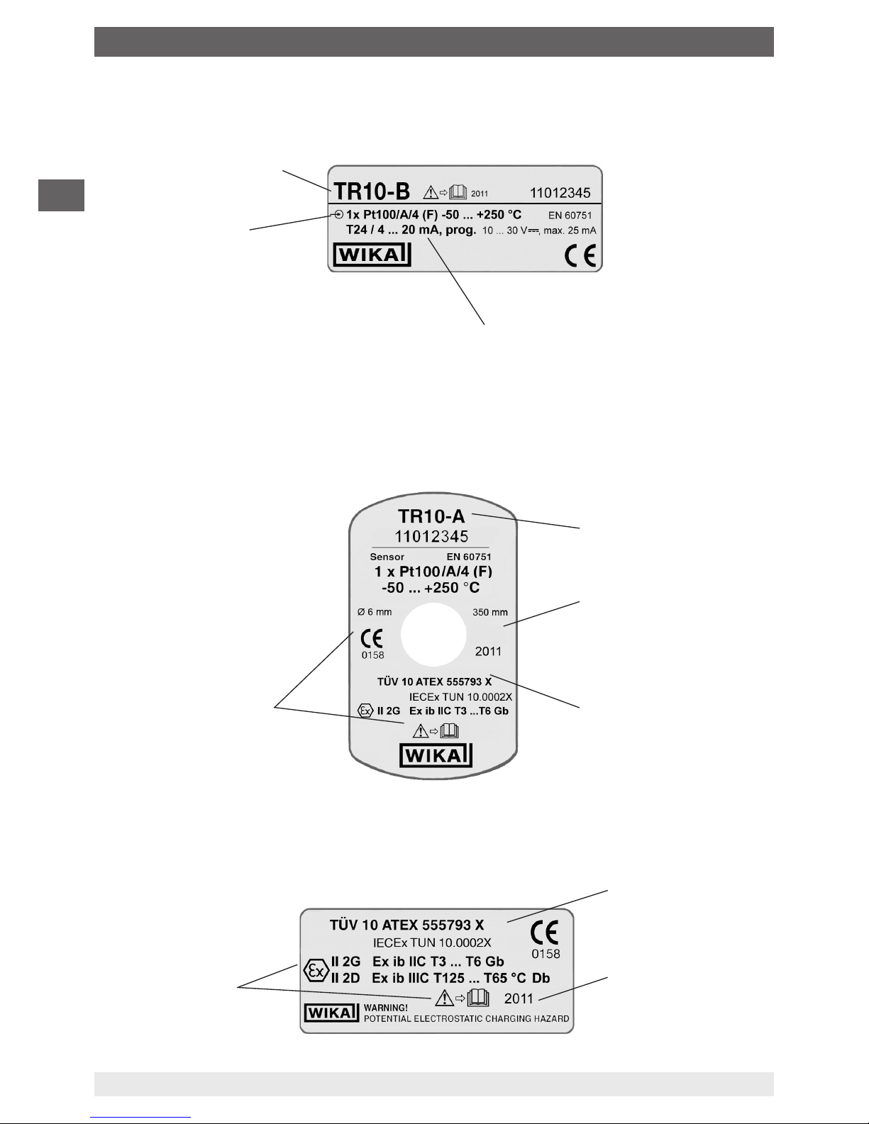
2.5 Labelling / safety marks
2.5.1 Product labels for resistance thermometers
Model
Sensor in accordance with
standard
■
F Thin-lm resistor
■
W Wire-wound resistor
Approval number
Year of manufacture
For an explanation of
symbols, see page 10
Transmitter model
(only for design with transmitter)
Year of manufacture
For an explanation of
symbols, see page 10
Approval number
Model
2. Safety
■
Product label for TR10-A measuring insert
■
Additional data for Ex instruments
Page 9

WIKA operating instructions RTD and TC, intrinsically safe designs
3345267.08 06/2011 GB/D
9
GB
2. Safety
2.5.2 Product labels for thermocouples
Model
Approval number
Year of manufacture
For an explanation of
symbols, see page 10
Transmitter model
(only for design with transmitter)
Year of manufacture
For an explanation of
symbols, see page 10
Approval number
Model
■
Product label for measuring insert TC10-A
■
Additional data for Ex instruments
"ungrounded"
Sensor in accordance with
standard
■
ungrounded
■
grounded
Legende:
■
ungrounded
welded insulated
■
grounded
welded to the sheath
Page 10
3345267.08 06/2011 GB/D
10 WIKA operating instructions RTD and TC, intrinsically safe designs
GB
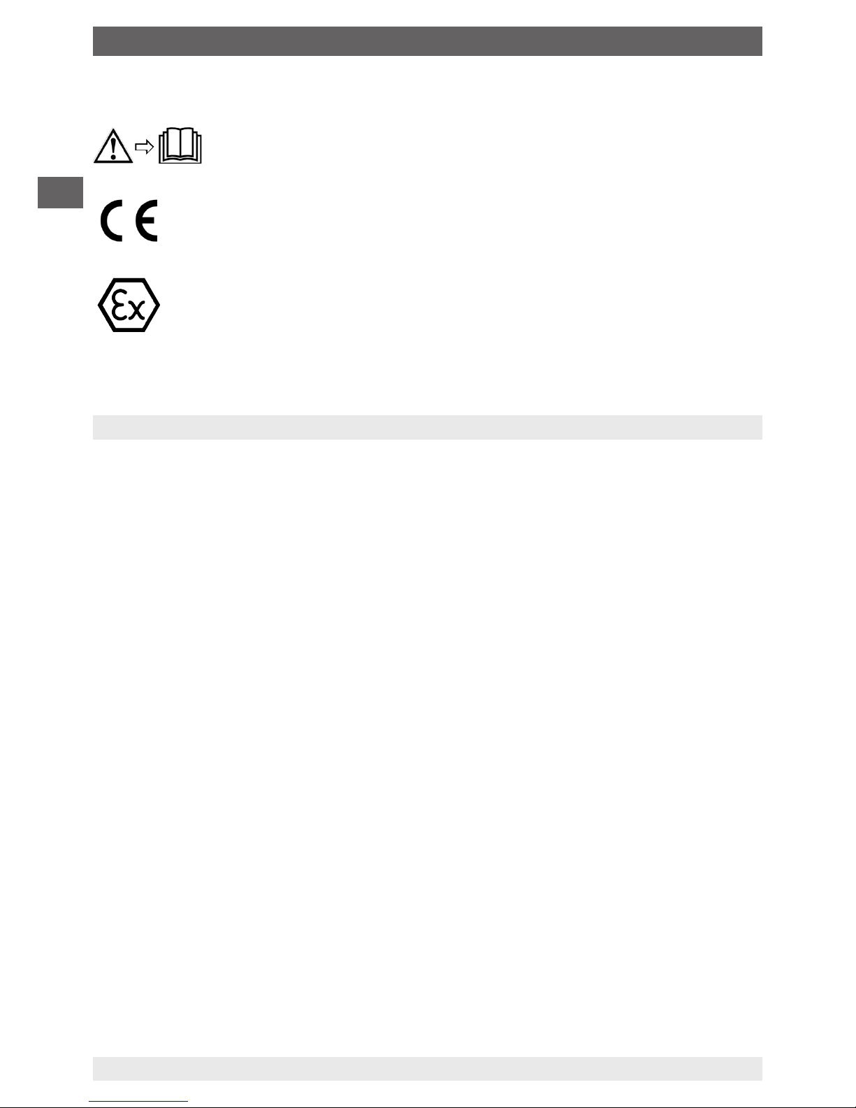
Explanation of symbols
Before mounting and commissioning the instrument, ensure you read the
operating instructions!
CE, Communauté Européenne
Instruments bearing this mark comply with the relevant European directives.
ATEX European Explosion Protection Directive
(Atmosphère = AT, explosible = EX)
Instruments bearing this mark comply with the requirements of the European
Directive 94/9/EC (ATEX) on explosion protection.
3. Specications
3.1 Resistance thermometer
Sensor connection method
■
2-wire The lead resistance is recorded as an error in the measurement.
■
3-wire With a cable length longer than approx. 30 m, measuring errors can occur.
■
4-wire
The internal lead resistance of the connecting wires is negligible.
Limiting error of the sensor per DIN EN 60751
■
Class B
■
Class A
■
Class AA
The combination of a 2-wire connection with Class A / Class AA is not permissible, since the lead
resistance of the measuring insert negates the higher sensor accuracy.
Basic values and limiting errors
Basic values and limiting errors for the platinum measurement resistances are laid down in
DIN EN 60751.
The nominal value of Pt100 sensors is 100 Ω at 0 °C.
The temperature coecient α can be stated simply to be between 0 °C and 100 °C with:
α = 3.85 ∙ 10-3 °C
-1
The relationship between temperature and electrical resistance is described by polynomialss,
which are also dened in DIN EN 60751. Moreover, this standard species the basic values in °C
steps in tabular form.
2. Safety / 3. Specications
Page 11

WIKA operating instructions RTD and TC, intrinsically safe designs
3345267.08 06/2011 GB/D
11
GB
Class Temperature range Limiting error in °C
Wire-wound (W) Thin-lm (F)
B -196 … +600 °C -50 … +500 °C ± (0.30 + 0.0050 | t |)
1)
A -100 … +450 °C -30 … +300 °C ± (0.15 + 0.0020 | t |)
1)
AA -50 … +250 °C 0 … 150 °C ± (0.10 + 0.0017 | t |)
1)
1) | t | is the value of the temperature in °C irrespective of the sign.
Bold: standard version
Resistance values and limiting deviations at selected temperatures (Pt100)
Temperature
in °C
(ITS 90)
Resistance value in Ω
Class B Class A Class AA
-196 19,69 ... 20,80 - -
-100 59,93 ... 60,58 60,11 ... 60,40 -
-50 80,09 ... 80,52 80,21 ... 80,41 80,23 ... 80,38
-30 88,04 ... 88,40 88,14 ... 88,30 88,16 ... 88,28
0 99,88 ... 100,12 99,94 ... 100,06 99,96 ... 100,04
20 107,64 ... 107,95 107,72 ... 107,87 107,74 ... 107,85
100 138,20 ... 138,81 138,37 ... 138,64 138,40 ... 138,61
150 156,93 ... 157,72 157,16 ... 157,49 157,91 ... 157,64
250 193,54 ... 194,66 193,86 ... 194,33 193,91 ... 194,29
300 211,41 ... 212,69 211,78 ... 212,32 -
450 263,31 ... 265,04 263,82 ... 264,53 -
500 280,04 ... 281,91 - -
600 312,65 ... 314,77 - -
This table represents the calibration process with predened temperatures. This means if a temperature
standard is available, the resistance value of the test piece must lie within the limits specied above.
For further information on accuracies and limits of use of resistance thermometers,
see data sheet IN 00.17 (download available at www.wika.de).
3.2 Thermocouples
Sensor type
Model
Recommended max. operating temperature
K (NiCr-Ni) 1200 °C
J (Fe-CuNi) 800 °C
E (NiCr-CuNi) 800 °C
T (Cu-CuNi) 400 °C
N (NiCrSi-NiSi) 1200 °C
S (Pt10% Rh-Pt) 1600 °C
R (Pt13% Rh-Pt) 1600 °C
B (Pt30% Rh-Pt6%-Rh) 1700 °C
3. Specications
Page 12

3345267.08 06/2011 GB/D
12 WIKA operating instructions RTD and TC, intrinsically safe designs
GB
Potential measuring uncertainties due to ageing eects
Thermocouples are subject to ageing and change their temperature/thermal voltage
characteristic. Type J thermocouples of (Fe-Cu-Ni) age slightly due to oxidation of the pure metal
leg. In types K and N thermocouples (NiCrSi-NiSi), high temperatures can result in substantial
changes to the thermal voltage due to chrome depletion in the NiCr leg, leading to a lower thermal
voltage.
This eect is accelerated if there is a shortage of oxygen, since a complete oxide layer, which
would protect it from further oxidation, cannot be formed on the surface of the thermocouple.
The chromium in the alloy is oxidised, but not the nickel, giving rise to "green rot" that eventually
destroys the thermocouple. When NiCr-Ni thermocouples that have been operating above 700 °C
are cooled quickly, this cooling causes certain states in the crystal structure (short-range order)
to freeze, which in Ttype K thermocouples can result in a change of the thermal voltage of up to
0.8 mV (K eect).
In Type N thermocouple (NiCrSi-NiSi), it has been possible to reduce the short-range-order
eect by alloying both legs with silicon. The eect is reversible and is largely eliminated again by
annealing above 700 °C, followed by slow cooling. Thin sheathed thermocouples are particularly
sensitive. Cooling in still air can even result in deviations of more than 1 K.
The application range of these thermometers is limited both by the permissible max. temperature
of the thermocouple and by the max. temperature of the thermowell material.
Listed thermocouples are available both as single or duplex thermocouples. The thermocouple
will be delivered with an insulated measuring point, unless explicitly specied otherwise.
Sensor limiting error
A cold junction temperature of 0 °C is taken as basis with the denition of the tolerance value
of thermocouples. When using a compensating cable or thermocouple cable, an additional
measuring error must be considered.
For limiting errors and further specications see current WIKA data sheet or order
documentation.
3. Specications
Page 13
WIKA operating instructions RTD and TC, intrinsically safe designs
3345267.08 06/2011 GB/D
13
GB
4. Design and function
4.1 Description
These thermometers (resistance thermometers and thermocouples) detect temperatures in
processes.
Depending on their design, these thermometers are suitable for low, medium and high process
requirements in hazardous areas.
Insulated measuring point
The model TRxx or model TCxx thermometers consist of a welded tube, a mineral-insulated
sheathed cable or ceramic-insulated thermal wires (in which the temperature sensor is located,
embedded in a ceramic powder), a temperature-resistant sealing compound, cement compound
or a thermal transfer paste.
Alternatives:
The measuring insert or the cable probe can also be provided in a tubular form. In this case, the
sensor is located in a welded tube and embedded in a ceramic powder, heat-conducting paste or
in a sealing compound suitable for this purpose.
The measuring insert for high-temperature thermocouples can also be assembled from thermal
wires insulated with ceramic rods or ceramic beads. The ceramic tube is cemented into a metallic
support tube using a temperature-resistant cement.
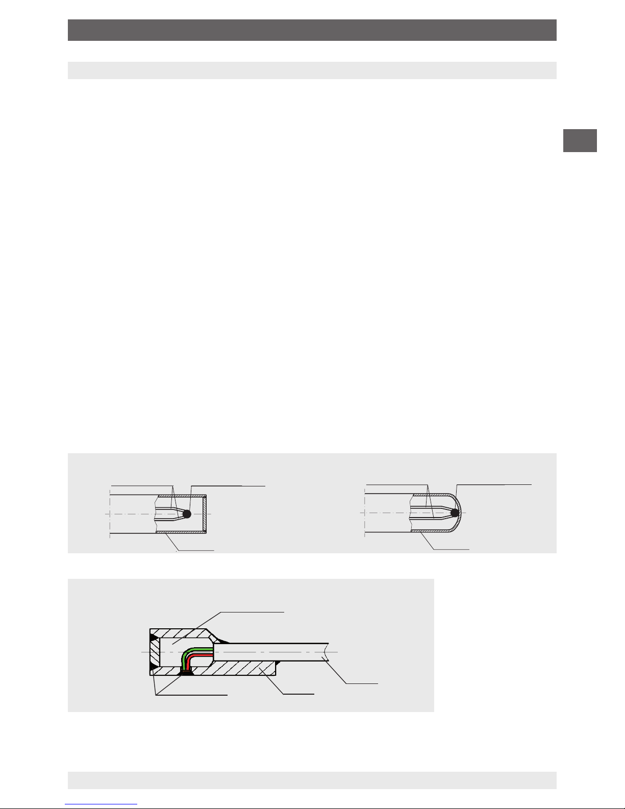
Thermocouples, non-insulated (grounded)
For special applications, for example surface temperature measurements, the sensors are in
direct contact with the protective sleeve, or the measuring points of thermocouples are welded to
the bottom (see chapter "7.1.1 Special conditions of use (X conditions)").
Measuring point insulated (ungrounded) Measuring point not insulated (grounded)
Thermocouple
Thermocouple
Measuring point
Measuring point
Sheath Sheath
AI203 powder
MI line
V-Pad
welded with
ller
V-Pad version
Measuring point not insulated
4. Design and function
Page 14

3345267.08 06/2011 GB/D
14 WIKA operating instructions RTD and TC, intrinsically safe designs
GB
Vibration resistance
The thermometers have an impact- and vibration-resistant design. The vibration resistance of the
basic model corresponds to DIN EN 60751 (up to 3 g), while for special designs higher loads are
possible. The impact resistance of all versions complies with the requirements of EN 60751, with
the exception of high-temperature thermocouples assembled from ceramic-insulated thermal
wires.
Electrical connection
In terms of connection, the thermometer is equipped with a housing and a connector or bare wire
ends. The housing design will contain the terminals or a certified transmitter. Optionally, separatelycertified digital displays can be built into the housing.
4.2 Scope of delivery
Cross-check scope of delivery with delivery note.
5. Transport, packaging and storage
5.1 Transport
Check instrument for any damage that may have been caused by transport.
Obvious damage must be reported immediately.
5.2 Packaging
Do not remove packaging until just before mounting.
Keep the packaging as it will provide optimum protection during transport (e.g. change in
installation site, sending for repair).
5.3 Storage
Permissible conditions at the place of storage:
■
Storage temperature:
Instruments without built-in transmitter: -40 ... +85 °C
Instruments with built-in transmitter:
see operating instructions of the transmitter in question
■
Humidity: 35 ... 85 % relative humidity (no condensation)
Avoidance of exposure to the following factors:
■
Direct sunlight or proximity to hot objects
■
Mechanical vibration, mechanical shock (putting it down hard)
■
Soot, vapour, dust and corrosive gases
Store the instrument in its original packaging in a location that fulls the conditions listed above. If
the original packaging is not available, pack and store the instrument as described below:
1. Wrap the instrument in an antistatic plastic lm.
2. Place the instrument, along with shock-absorbent material, in the packaging.
3. If stored for a prolonged period of time (more than 30 days), place a bag, containing a
desiccant, inside the packaging.
4. Design and function / 5. Transport, packaging and storage
Page 15

WIKA operating instructions RTD and TC, intrinsically safe designs
3345267.08 06/2011 GB/D
15
GB
WARNING!
Before storing the instrument (following operation), remove any residual media. This
is of particular importance if the medium is hazardous to health, e.g. caustic, toxic,
carcinogenic, radioactive, etc.
6. Commissioning, operation
WARNING!
When the thermometer is mounted, the temperature must not drop below the allowed
operating temperature (environment, medium) or exceed it, even when taking
convection and heat radiation into account!
WARNING!
Thermometers must be earthed if dangerous voltages could be expected at the
connection wires (caused, for example, by mechanical damage, electrostatic
discharge or induction)!
6.1 Electrical connection
CAUTION!
■
Damage to cables and wires, and to connection points, must be avoided
■
Provide nely stranded conductor ends with end splices (cable assembly)
■
Both the internal capacitance and inductance must be considered
For the electrical connections of thermometers (e.g. connection circuit diagrams, tolerance
values, etc.), please refer to the appropriate data sheets. If head transmitters or digital displays
have been built into the connection housing, these data sheets must also be given proper
consideration.
5. Transport, packaging and storage / 6. Commissioning, operation
Page 16
3345267.08 06/2011 GB/D
16 WIKA operating instructions RTD and TC, intrinsically safe designs
GB
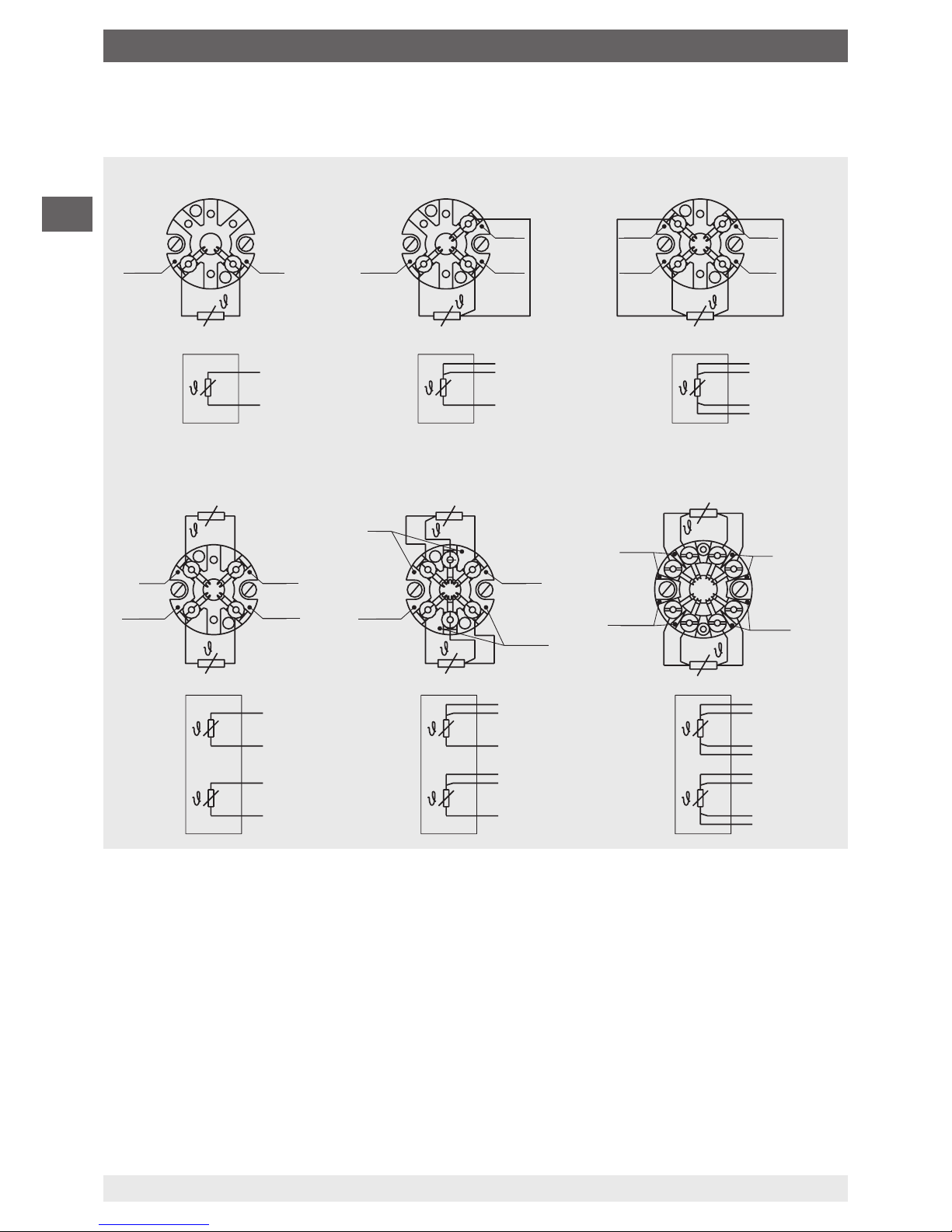
6.2 Electrical connection of resistance thermometers
6.2.1 Resistance thermometer with terminal block
3160629.06
red
1 x Pt100, 2-wire 1 x Pt100, 3-wire 1 x Pt100, 4-wire
white
white
red
red
red
red
white
white
white
white
white
white
red
red
red
red
red
2 x Pt100, 2-wire
2 x Pt100, 3-wire
2 x Pt100, 4-wire
red
white
white
red
red
white
black
yellow
yellow
yellow
black
black
white
white
red
red
red
red
black
black
black
black
yellow
yellow
yellow
red
white
black
yellow
white
6. Commissioning, operation
Page 17
WIKA operating instructions RTD and TC, intrinsically safe designs
3345267.08 06/2011 GB/D
17
GB
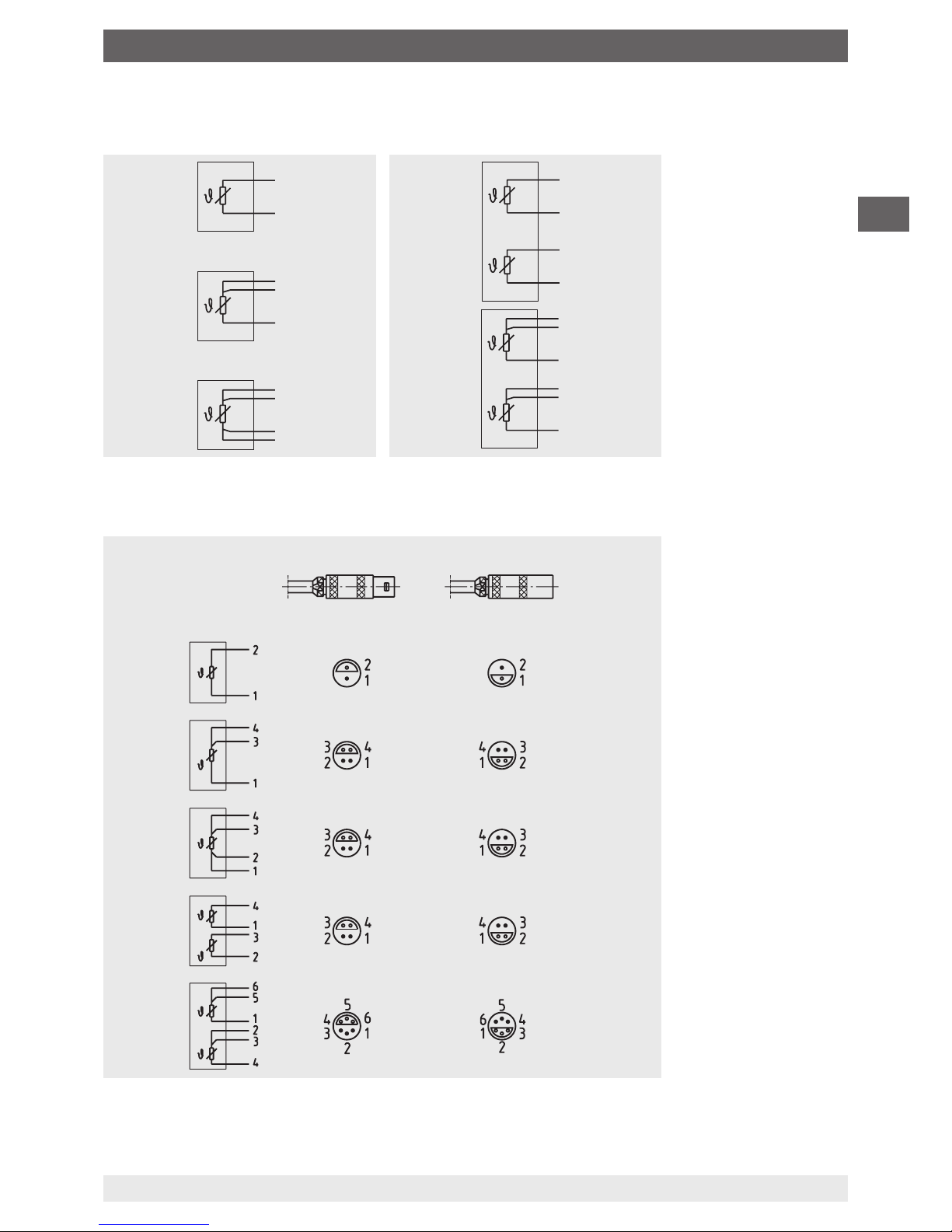
6.2.2 Resistance thermometer with cable or connector
Without
connector
Lemosa
connector
3366036.02
1 x Pt100
2-wire
1 x Pt100
3-wire
1 x Pt100
4-wire
2 x Pt100
2-wire
2 x Pt100
3-wire
red
red
red
red
red
red
red
red
white
white
white
white
Connector
(male)
View from the front
Socket (female)
View from the front
white
white
black
black
black
yellow
yellow
3160629.06
6. Commissioning, operation
Page 18

3345267.08 06/2011 GB/D
18 WIKA operating instructions RTD and TC, intrinsically safe designs
GB
6.3 Electrical connection of thermocouples
Cable colour coding of thermocouples
Sensor type Standard Positive Negative
K DIN EN 60584 green white
J DIN EN 60584 black white
E DIN EN 60584 violet white
T DIN EN 60584 brown white
N DIN EN 60584 pink white
6.3.1 Thermocouples with terminal block
Binder
Series 680
Binder
Series 680
Binder
Series 680
Binder
Series 680
Binder
Series 692
Binder screw/plug-in
connector
3366142.02
Connector
(male)
View of the connector contacts
Socket (female)
View of the socket contacts
3166822.03
Single thermocouple Dual thermocouple
The colour coding at the positive
connection to the devices always
decides the correlation of polarity
and connection terminal.
6. Commissioning, operation
Page 19

WIKA operating instructions RTD and TC, intrinsically safe designs
3345267.08 06/2011 GB/D
19
GB
6.3.2 Thermocouples with cable or connector
Lemosa connector,
male at the cable
Binder connector,
male at the cable
(screw/plug-in connection)
Single
thermocouple
For the marking of
the cable ends, see
table
Cable
Dual
thermocouple
Plus and minus are marked.
For dual thermocouples, two thermal
connectors are used.
Thermal connector
6.4 Multipoint thermocouples (as per 8.4 and 8.5)
They are usually equipped with a housing in which transmitters or terminal blocks are mounted.
The transmitters/digital displays are fastened mechanically (e.g. rail system in housing or holder
in connection head) and installed in accordance with EN/IEC 60079-11 and EN/IEC 60079-14.
Optionally, depending on design, the housings can be equipped with or without terminals (e.g.
terminal blocks, etc.) in accordance with EN/IEC 60079-11 and EN/IEC 60079-14.
When using several transmitters/digital displays, the housing volume increases as a function of
the "heat source", thus increasing the volume to be heated. This guarantees that the housing
surface temperature does not increase signicantly.
WARNING!
When using no terminals and line wiring, compliance with the installation regulations
in accordance with EN/IEC 60079-11 and EN/IEC 60079-14 must be guaranteed.
6.5 Cable glands
In thermometers equipped with connection heads, the cable glands must be fully sealed in order
to ensure that the necessary ingress protection is reached.
Requirements for meeting ingress protection
■
Only use cable glands within their indicated clamping range (cable diameter suitable for the
cable gland)
■
Do not use the lower clamping area with very soft cable types
■
Only use circular cross-section cables (if necessary, slightly oval in cross-section)
■
Do not twist the cable
6. Commissioning, operation
Page 20

3345267.08 06/2011 GB/D
20 WIKA operating instructions RTD and TC, intrinsically safe designs
GB
■
Repeated opening/closing is possible; however only if necessary, as it might have a
detrimental eect on the protection class
■
For cable with a pronounced cold-ow behaviour the screw connection must be fully tightened
6.6 Parallel threads
If the thermometer connecting head, extension neck, thermowell or process connection are
connected with parallel threads (e.g. G ½, M20 x 1.5 ...), these threads must be secured using
seals which prevent liquids from penetrating into the thermometer.
As standard, WIKA uses copper prole seals for the connection between the neck tube and the
thermowell, and at paper seals for the connection of the connection head and the extension
neck or thermowell.
If the thermometer and the thermowell are already connected, the seals will already be mounted.
The plant operator must check whether the seals are suitable for the operating conditions and
must replace them, if necessary, with suitable seals.
For thermometers without a thermowell, and/or where these are delivered separately, the seals
are not included and must be ordered separately.
Tighten the threads by hand when carrying out the nal assembly on the plant. This will
correspond to the delivery status of the premounted components. The nal tightening torque
should be applied using a spanner (half rotation).
The seals must be replaced after dismantling!
The seals can be ordered from WIKA, indicating the WIKA order number and/or the
designation (see table).
WIKA
Order No.
Designation Suitable for
threads
11349981 per DIN 7603 Form C 14 x 18 x 2 -CuFA G ¼, M14 x 1.5
11349990 per DIN 7603 Form C 18 x 22 x 2 -CuFA M18 x 1.,5, G ⅜
11350008 per DIN 7603 Form C 21 x 26 x 2 -CuFA G ½, M20 x 1.5
11350016 per DIN 7603 Form C 27 x 32 x 2.5 -CuFA G ¾, M27 x 2
11367416 per DIN 7603 Form C 20 x 24 x 2 -CuFA M20 x 1.5
1248278 per DIN 7603 D21.2 x D25.9 x 1.5 -Al G ½, M20 x 1.5
3153134 per
DIN 7603 Form C D14.2 x D17.9 x 2 -StFA
G ¼, M14 x 1.5
3361485 per
DIN 7603 Form C D33.3 x D38.9 x 2.5 -StFA
G 1
Legend:
CuFA = Copper, max. 45HB
a
; lled with asbestos-free sealing material
Al = Aluminium Al99
; F11, 32 to 45 HB
b
StFA = Soft iron, 80 to 95 HBa; lled with asbestos-free sealing material
6. Commissioning, operation
Page 21

WIKA operating instructions RTD and TC, intrinsically safe designs
3345267.08 06/2011 GB/D
21
GB
6.7 Tapered threads (NPT)
Connections with tapered threads (NPT) are self-sealing and normally must not be sealed. It
should be checked whether it may be necessary to seal them additionally with Teon tape or
hemp. The threads must be lubricated with a suitable lubricant before tting.
Tighten the threads by hand when carrying out the nal assembly on the plant. This will
correspond to the delivery status of the premounted components. The nal tightening and sealing
must be made with a spanner (1.5 to 3 rotations).
7. Information on mounting and operation in hazardous areas (Europe)
WARNING!
In hazardous areas the use of a model TR10-A measuring insert without a suitable
connection head (case) is not permissible!
Where required a suitable thermowell is to be used.
7.1 General information on explosion protection
The requirements of the 94/9/EC (ATEX) directive must be followed. Additionally the
specications of the respective national regulations concerning Ex usage apply.
A) The responsibility for classication of zones lies with the plant operator and not the
manufacturer/supplier of the equipment.
B) The plant operator guarantees, and is solely responsible, that all thermometers in use are
identiable with respect to all safety-relevant characteristics. Damaged thermometers may not
be used. Repairs may only be completed using original spare parts from the original supplier;
otherwise the requirements of the approval are not fullled.
The manufacturer shall not be responsible for constructional modications after delivery of the
instruments.
C) If a component of electrical equipment, on which the explosion protection depends, is
repaired, then the electrical equipment may only be put back into use, after an authorised
expert has stated that it corresponds to the fundamental characteristics of the requirements for
explosion protection. In addition this expert must provide a certicate for this and provide the
equipment with a test mark.
D) Item C) shall not apply if the component was repaired by the manufacturer in accordance with
the requirements and regulations.
6. Commissioning, operation / 7. Information on mounting and ...
Page 22

3345267.08 06/2011 GB/D
22 WIKA operating instructions RTD and TC, intrinsically safe designs
GB
E) When using transmitters and digital displays, the following must be observed:
The contents of these operating instructions and those of the transmitter.
The relevant regulations for installation and use of electrical systems.
The regulations and directives regarding explosion protection. Transmitters and digital
displays must have their own approval.
F) When ordering spare parts, the parts that are to be replaced must be specied exactly:
■
Ignition protection type (here Ex i)
■
Approval No.
■
Order No.
■
Manufacturing No.
■
Order item
7.1.1 Special conditions of use (X conditions)
Versions with Ø <3 mm or "non-insulated" versions are operationally non-compliant with section
6.3.12 of EN/IEC 60079-11. Therefore, from a safety-relevant point of view, these intrinsically
safe circuits must be considered galvanically connected to the earth potential, which is why
equipotential bonding must be secured for the entire installation of the intrinsically safe circuits. In
addition, for the connection, separate conditions in accordance with EN/IEC 60079-14 must be
observed.
Electrostatic discharges must be avoided in instruments, that due to their design, do not conform
to the electrostatic requirements in accordance with EN/IEC 60079-0.
The transmitters and digital displays used must have their own EN/IEC approval. The installation
conditions, electrical connected loads, temperature classes or maximum surface temperatures
for use in potentially explosive dust atmospheres and permissible ambient temperatures can be
seen from the relevant approvals and must be observed.
Thermal backow from the process, that exceeds the permissible ambient temperature of
the transmitter, must not be allowed to occur. It must be prevented by installing suitable heat
insulation or a neck tube of suitable length.
If the wall thickness is below 1 mm, the instruments must not be subjected to ambient stresses
that may have an adverse eect on the partition wall. Alternatively, a thermowell of suitable
minimum wall thickness may be used.
When using a thermowell/neck tube, the overall instrument must be designed such that it
allows installation in a way that results in a suciently tight gap (IP 67) or a ameproof gap
(EN/IEC 60079-1) towards the less hazardous area.
The circuits of the coaxial element are operationally connected to one another. When applied in
practice a separate assessment must be made, or special conditions may have to be observed
when connecting the coaxial multipoint thermocouple. In addition, an assessment of the
intrinsically safe system (e.g. when connecting several sensor circuits of dierent transmitters to
one another) must be made.
7. Information on mounting, operation in hazardous areas (Europe)
Page 23

WIKA operating instructions RTD and TC, intrinsically safe designs
3345267.08 06/2011 GB/D
23
GB
When housings are used, they must either have their own suitable approval or comply with the
minimum requirements. IP protection: at least IP 20 (at least IP 65 for dust), applies to all housings.
However, light metal housings must be suitable in accordance with EN/IEC 60079-0 Section 8.1.
In addition, non-metallic housings or powder-coated housings must meet the requirements of
EN/IEC 60079-0 or have a suitable warning note.
Protective measures for applications that require EPL Ga or Gb:
Operational friction or impact between equipment parts made of light metals or their alloys (e.g.
aluminium, magnesium, titanium or zirconium) with equipment parts made of iron/steel is not
permitted. Operational friction or impact between two light metals is permitted.
7.1.2 Ex marking
For applications without transmitter (digital displays) requiring instruments of equipment Group II
(potentially explosive gas atmospheres), the following temperature class classication and
ambient temperature ranges apply:
Table 1
Marking
Temperature
class
Ambient temperature range (T
a
)
Max. surface temperature (T
max
)
at the sensor or thermowell tip
II 1G Ex ia IIC T6 Ga
II 1/2G Ex ib IIC T6 Ga/Gb
T6
(-50)1) -40 ... +80 °C
TM (temperature of the medium) +
self-heating
For this, the special conditions (17)
must be observed.
II 1G Ex ia IIC T5 Ga
II 1/2G Ex ib IIC T5 Ga/Gb
T5
(-50)1) -40 ... +95 °C
II 1G Ex iaD IIC T4 Ga
II 1/2G Ex ib IIC T4 Ga/Gb
II 1G Ex ia IIC T3 Ga
II 1/2G Ex ib IIC T3 Ga/Gb
T4, T3
(-50)1) -40 ... +100 °C
1) The values in brackets apply to special designs. These sensors are manufactured using special sealing compounds. Moreover, they feature housings made of stainless steel and cable glands for low-temperature ranges
When there is a built-in transmitter and/or a digital display, the special conditions from the type
examination certicate (see item 17) apply.
7. Information on mounting, operation in hazardous areas (Europe)
Page 24

3345267.08 06/2011 GB/D
24 WIKA operating instructions RTD and TC, intrinsically safe designs
GB
For applications requiring instruments of equipment Group II (potentially explosive dust
atmospheres), the following surface temperatures and ambient temperature ranges apply:
Table 2
Marking
Power
P
i
Ambient
temperature
range (T
a
)
Max. surface temperature
(T
max
) at the sensor or
thermowell tip
II 1D Ex ia IIIC T65 °C Da
II 1/2D Ex ib IIIC T65 °C Da/Db
750 mW (-50)1) -40 ... +40 °C
TM (temperature of the medium)
+ self-heating
For this, the special conditions
(17) must be observed.
II 1D Ex ia IIIC T95 °C Da
II 1/2D Ex ib IIIC T95 °C Da/Db
650 mW
(-50)1) -40 ... +70 °C
II 1D Ex ia IIIC T125 °C Da
II 1/2D Ex ib IIIC T125 °C Da/Db
550 mW
(-50)1) -40 ... +100 °C
1) The values in brackets apply to special designs. These sensors are manufactured using special sealing
compounds. Moreover, they feature housings made of stainless steel and cable glands for low-temperature
ranges.
When there is a built-in transmitter and/or a digital display, the special conditions from the type
examination certicate (see item 17) apply.
Use in methane atmospheres
Owing to the higher minimum ignition energy of methane, the instruments can also be used
where methane causes a potentially explosive atmosphere. The instrument can be optionally
marked with IIC + CH
4
.
For applications that require EPL Gb or Db, instruments with "ia" marking may also be used in
measuring circuits of type "ib".
7.2 Temperature class classication, ambient temperatures
The permissible ambient temperatures depend on the temperature class, the housings used and
any transmitters and/or digital displays tted as options.
When a thermometer is connected to a transmitter and/or a digital display, the lowest value
of either the ambient temperature limits or the highest temperature class will apply. The lower
temperature limit is -40 °C; and -50 °C for special designs.
Where there are neither transmitters nor digital displays mounted within the housing, there will
also be no additional warming.
With a built-in transmitter (optionally with digital display), heating caused by the operation of the
transmitter or digital display may occur.
7. Information on mounting, operation in hazardous areas (Europe)
Page 25

WIKA operating instructions RTD and TC, intrinsically safe designs
3345267.08 06/2011 GB/D
25
GB
For applications without transmitters (digital displays) that require Group II instruments
(potentially explosive gas atmospheres), the following temperature class classication and
ambient temperature ranges apply:
Temperature class Ambient temperature range (Ta)
T6 (-50) -40 … +80 °C
T5 (-50) -40 … +95 °C
T4, T3 (-50) -40 … +100 °C
See and observe the permissible ambient temperatures and surface temperatures for third-party
products from the relevant approvals and/or data sheets.
Example
For instruments tted with a DIH10 transmitter and digital display, for example, the following limit
for temperature class classication applies:
Temperature class Ambient temperature range (Ta)
T6 -40 … +60 °C
For applications that require Group II instruments (potentially explosive dust atmospheres), the
following surface temperatures and ambient temperature ranges apply:
Power Pi Ambient temperature range (Ta)
750 mW (-50) -40 … +40 °C
650 mW (-50) -40 … +70 °C
550 mW (-50) -40 … +100 °C
See and observe the permissible ambient temperatures and surface temperatures for third-party
products from the relevant approvals and/or data sheets.
The values in brackets apply to special designs. These sensors are manufactured using special
sealing compounds. Moreover, they are equipped with connection heads made of stainless steel
and cable glands for the low-temperature range.
These thermometers are suitable for temperature classes T6...T3 in accordance with the
approval certicate. This applies to instruments without built-in transmitters and/or digital
displays. Thermometers equipped with transmitters and/or digital displays are for use in
temperature classes T6...T4 and are marked accordingly. Using equipment for applications which
require a lower temperature class (e.g. T2) than the marked one is permissible. In doing so, it
must be ensured that the maximum ambient temperature for safe operation of the instrument is
not exceeded.
7. Information on mounting, operation in hazardous areas (Europe)
Page 26

3345267.08 06/2011 GB/D
26 WIKA operating instructions RTD and TC, intrinsically safe designs
GB
FF-00147.00
Tx10
Tx10 Tx40 Tx40
Option: with built-in
transmitter e.g. T32
Option:
with connector
MI line
Option:
with connector
cable
Tx10-A
Tx10-A
T3T3T3
T3
Process connection
Process connection
Process connection
Process connection
1)
permissible temperatures at
T1: (-50) -40 °C < Ta < +300 °C
T3: (-50) -40 °C < Ta < +150 °C
T4: (-50) -40 °C < Ta < +100 °C
T4
T4
Transmitter
T4
connector
T4
connector
T1 T1 T1 T1
T4
Transmitter
: (-50) -40 °C < Ta < +85 °C
T4
connector
: (-50) -40 °C < Ta < +85 °C
1) Temperature zone undened
1) 1) 1)
7.3 Temperature carry-over from the process
A heat backow from the process that exceeds the operating temperature of the transmitter
(digital display) or housing is not permissible and must be prevented by installing suitable heat
insulation or a neck tube of suitable length.
7.3.1 Overview of the temperature zones
7. Information on mounting, operation in hazardous areas (Europe)
Page 27

WIKA operating instructions RTD and TC, intrinsically safe designs
3345267.08 06/2011 GB/D
27
GB
3160670.06
Threaded connection
Thread
Thread
11355647.01
Thread
Thread
(NPT)
7.3.2 Increasing the separation of the connection components and hot surfaces
The neck distance (N) is dened as the distance between the lower edge of the connection head
(or the housing) to the heat-emitting surface. The temperature to be expected at the lower edge
of the connection head or housing is, at most, 100 °C. The conditions for built-in transmitters or
displays must be observed. If required, the neck length must be increased accordingly.
For thermometers tted with a connection lead, the temperature at the interface with the
connecting cable is restricted. The maximum is 150 °C. To ensure that the permissible
temperature is not exceeded, the dimension X must be selected accordingly.
7. Information on mounting, operation in hazardous areas (Europe)
Page 28

3345267.08 06/2011 GB/D
28 WIKA operating instructions RTD and TC, intrinsically safe designs
GB
To help select the minimum neck length, the following standard values have been determined.
Maximum temperature of the
medium
Recommendation for
dimension N
Recommendation for
dimension X
100 °C - 135 °C 20 mm 20 mm
200 °C 50 mm 50 mm
>200 °C ≤ 450 °C 100 mm 100 mm
WARNING!
For reasons of work safety and saving of resources, hot surfaces should be protected
against accidental touch and energy loss by means of insulation.
7.4 Mounting examples in hazardous areas
7.4.1 Possible installation methods with the marking II 1G Ex ia IIC T6 Ga or
II 1D Ex ia IIIC T65 °C Da
7. Information on mounting, operation in hazardous areas (Europe)
Zones 0, 1, 2 or Zones 20, 21, 22
Hazardous area
Safe area
Thermowell
Thermowell
welded
TWxx
TWxx
Process
connection
Connection head/
Field housing
Tx10-B
Tx10-C
Tx10-C
Tx10-D
Tx10-H
Tx10-H
Option:
with built-in
transmitter:
e.g. T32
Tx10-A
Process
connection
Compression
tting
Associated
electrical equipment
Intrinsically
safe supply or
suitable barrier
e.g. transmitter power supply
KFD2-STC4-Ex1
WIKA Art. No.: 2341268
e.g. Zener barrier
Z954 for Pf100-3L
WIKA Art. No.: 3247938
Intrinsically
safe supply or
suitable barrier
Intrinsically
safe supply or
suitable barrier
Intrinsically
safe supply or
suitable barrier
Tx10-A
Tx10-A
Tx10-A
Page 29

WIKA operating instructions RTD and TC, intrinsically safe designs
3345267.08 06/2011 GB/D
29
GB
Zones 1, 2 or
Zones 21, 22
Hazardous area
Safe area
Thermowell
Thermowell
welded
TWxx
TWxx
Process
connection
Connection head/
Field housing
Tx10-B
Tx10-C
Tx10-C
Tx10-D
Tx10-H
Tx10-H
Option:
with built-in
transmitter:
e.g. T32
Tx10-A
Process
connection
Compression
tting
Associated
electrical equipment
Intrinsically
safe supply or
suitable barrier
e.g. transmitter power supply
KFD2-STC4-Ex1
WIKA Art. No.: 2341268
e.g. Zener barrier Z954
for Pf100-3L
WIKA Art. No.: 3247938
Intrinsically
safe supply or
suitable barrier
Intrinsically
safe supply or
suitable barrier
Intrinsically
safe supply or
suitable barrier
Tx10-A
Tx10-A
Tx10-A
Zones 0, 1, 2 or
Zones 20, 21, 22
The sensor together with housing or connection head is located in Zone 0 (Zone 20). An Ex
ia type circuit must be used. A zone separation is deemed to exist if the process connection
guarantees a suciently tight gap (IP 67) between the less hazardous zone and the Zone 0.
Examples of suitable process connections include gas-tight standardised industrial anges,
threaded connections or pipe connections.
7.4.2 Possible installation methods with the marking II 1/2 Ex ib IIC T6 Ga/Gb or
II 1/2 D Ex ib IIIC T65 °C Da/Db
The sensor or thermowell tip protrudes into Zone 0. The housing or connection head is in Zone 1
(Zone 21) or Zone 2 (Zone 22). It is sucient to use an Ex ib type circuit.
Zone separation is guaranteed if suciently-tight (IP 67) process connections are used.
Examples of suitable process connections include gas-tight standardised industrial anges,
threaded connections or pipe connections.
7. Information on mounting, operation in hazardous areas (Europe)
Page 30

3345267.08 06/2011 GB/D
30 WIKA operating instructions RTD and TC, intrinsically safe designs
GB
The welded parts, process connections, compression ttings, thermowells or housings used
must be designed such that they withstand all inuencing variables resulting from the process,
such as temperature, ow forces, pressure, corrosion, vibration and impacts.
7.4.3 Partition wall for use in Zone 0 or Zone 1/2 or separation between hazardous area
and non-hazardous area
If the wall thickness is less than 1 mm, the instrument must also be marked with an "X" or a safety
instruction in accordance with 29.2 of EN/IEC 60079-0, with the special proviso that for safe use
it must not be subjected to ambient stresses that may have an adverse eect on the partition
wall. If the partition wall is continuously subjected to vibrations (e.g. vibrating membranes), its
fatigue limit at the maximum amplitude must be stated in the documentation (see Section 4.2.5.2,
EN/IEC 60079-26).
Alternatively, a thermowell of suitable minimum wall thickness may be used by the customer.
When using a thermowell/neck tube, the overall instrument must be constructed such that
it allows installation in a way that results in a suciently tight gap (IP 67) or a ame path
(EN/IEC 60079-1) towards the less hazardous area.
8. Electrical connection values
8.1 Electrical data without built-in transmitter or digital display
For Group II instruments (potentially explosive gas atmospheres)
*3,
the following maximum
connection values apply:
U
i
= DC 30 V
I
i
= 550 mA
P
i
(at the sensor *1) = 1.5 W
For Group II instruments (potentially explosive dust atmospheres), the following maximum
connection values apply:
U
i
= DC 30 V
I
i
= 550 mA
P
i
(at the sensor *2) = For the values, see "Table 2" (column 2) on page 24
*1 The permissible power to the sensor depends on the temperature of the medium TM, the temperature class
and the thermal resistance Rth, but shall not be more than 1.5 W.
For calculation examples, see chapter "9. Calculation examples for self-heating at the sensor/thermowell tip".
*2 The permissible power to the sensor depends on the temperature of the medium TM, the maximum allowed
surface temperature and the thermal resistance Rth, but shall not be more than the values from "Table 2"
(Column 2), see above.
*3 Use in methane atmospheres
Owing to the higher minimum ignition energy of methane, the instruments can also be used where methane
causes a potentially explosive atmosphere. The instrument can be optionally marked with IIC + CH4.
7. Information on mounting and ... / 8. Electrical connection values
Page 31

WIKA operating instructions RTD and TC, intrinsically safe designs
3345267.08 06/2011 GB/D
31
GB
The internal inductance (Li) and capacitance (Ci) of standard measuring inserts in accordance
with DIN 43735 are negligible. The values for cable probes and very long sheathed-cable/
resistance thermometers can be seen from the rating plate and must be taken into account when
connecting them to an intrinsically safe power supply.
Sensor circuit in Ex ia or ib, IIC intrinsic safety ignition protection
Only for connection to intrinsically safe circuits with the following maximum output values for
Group II instruments (potentially explosive gas atmospheres):
U
o = DC 30 V
I
o = 550 mA
P
o = 1.5 W
For Group II instruments (potentially explosive dust atmospheres), the following maximum output
values apply to their connection to intrinsically safe circuits:
Uo = DC 30 V
Io = 550 mA
Po = For the values, see "Table 2" (Column 2) on page 24
8.2 Electrical data for built-in transmitters or digital displays
For the sensor circuit, the values mentioned in 8.1 apply.
Signal circuit in Ex ia or ib, IIC intrinsic safety ignition protection
U
i
=
depending on the transmitter/digital display
I
i
=
depending on the transmitter/digital display
P
i
=
in the housing: depending on the transmitter/digital display
C
i
=
depending on the transmitter/digital display
L
i
=
depending on the transmitter/digital display
The transmitters and digital displays used must have their own certication in accordance
with EN/IEC. The installation conditions and electrical connection values can be seen from the
relevant approvals and must be observed.
8.3 Electrical data with built-in transmitter in accordance with the FISCO model
The transmitters/digital displays used for the application range in accordance with the FISCO
model are considered FISCO eld units. The requirements in accordance with EN/IEC 60079-27,
and the connection conditions of the approvals in accordance with FISCO, apply.
8.4 TC95/TR95 multipoint thermocouples
Assembly of multipoint thermocouples from individual sheathed cables
For the individual insulated sheathed cable, the values mentioned in 8.1 apply. For operationally
grounded multipoint thermocouples, the sum of all the sensors must comply with the abovementioned values. For applications in dust areas, the values from "Table 2" (Column 2) on page
23 must be observed.
8. Electrical connection values
Page 32

3345267.08 06/2011 GB/D
32 WIKA operating instructions RTD and TC, intrinsically safe designs
GB
8.5 TC93 coaxial multipoint thermocouple
WARNING!
The circuits of the coaxial multi-point thermocouple are operationally connected to
one another. When applied in practice, a separate assessment must be made, and/or
special conditions may have to be observed when connecting the coaxial multipoint
thermocouple. In addition, an assessment of an intrinsically safe system (e.g. when
connecting several sensor circuits of dierent transmitters to one another) must be
made.
9. Calculation examples for self-heating at the sensor/thermowell tip
The self-heating at the sensor tip or thermowell tip depends upon the sensor type (TC/RTD),
the probe diameter, the thermowell design and the power supplied to the sensor in the event of
a failure. The table below shows the possible combinations. The table shows that when a failure
occurs, thermocouples produce much less self-heating than resistance thermometers.
Thermal resistance [R
th
in K/W]
Sensor Probe Ø in mm
2.0<3.0
3.0<6.0
6 - 8 3.0 -
6.0
1)
0.5<1.5
1.5<3.0
3.0<6.0
6.0-
12.0
Sensor type RTD RTD RTD RTD TC TC TC TC
without thermowell 245 110 75 225 105 60 20 5
with multi-part thermowell
(straight and tapered)
(e.g. TW22, TW35, TW40, TW45, etc.)
135 60 37 - - - 11 2.5
with thermowell - machined from solid
material (straight and tapered)
(e.g. TW10, TW15, TW20, TW25, TW30,
TW50, TW55, TW60, etc.)
50 22 16 - - - 4 1
Special thermowell – EN 14597 - - 33 - - - - 2.5
Tx55 (tubular holder) - 110 75 225 - - 20 5
Built into a blind bore
(minimum wall thickness 5 mm)
50 22 16 45 22 13 4 1
1) surface-sensitive
When using multiple sensors and simultaneous operation, the sum of the individual powers must
not exceed the value of the maximum permissible power. The maximum permissible power must
be limited to 1.5 W maximum. This must be guaranteed by the plant operator.
8. Electrical connection values / 9. Calculation examples for ...
Page 33

WIKA operating instructions RTD and TC, intrinsically safe designs
3345267.08 06/2011 GB/D
33
GB
9.1 Calculation example for RTD measuring point with thermowell
Use at the partition wall to Zone 0: Calculate the maximum permissible temperature T
max
at the
thermowell tip for the following combination:
RTD measuring insert Ø 6 mm with built-in model T32.1S head-mounted transmitter, tted into
a Design 3F multi-part thermowell . Power supply is, for example, via a Model KFD2-STC4-EX1
transducer power supply (WIKA Article No. 2341268).
T
max
is obtained by adding the temperature of the medium and the self-heating. The self-heating
of the thermowell tip depends on the supplied power P
o
of the transmitter and the thermal
resistance R
th
.
The following formula is used for the calculation: T
max
= Po x Rth + T
M
T
max
= Surface temperature (max. temperature at the thermowell tip)
P
o
= from transmitter data sheet
R
th
= Thermal resistance [K/W]
TM = Temperature of the medium
Prerequisite is an ambient temperature T
amb
of -20 ... +40 °C.
Example
Resistance thermometer RTD
Diameter: 6 mm
Temperature of the medium T
M
= 150 °C
Supplied power: P
o
= 15.2 mW
Temperature Class T3 (200 °C) must not be exceeded
Thermal resistance [R
th
in K/W] from table = 37 K/W
Self-heating: 0.0152 W x 37 K/W = 0.56 K
T
max
= TM + self-heating: 150 °C + 0.56 °C = 150.56 °C
The result shows that in this case self-heating at the thermowell tip is negligible. As safety
clearance for type-examined instruments (for T6 to T3), another 5 °C must be subtracted from the
200 °C; hence 195 °C would be permissible. This means that in this case temperature class T3 is
not exceeded.
Additional information
Temperature class for T3 = 200 °C
Safety clearance for type-examined instruments (T6 to T3)
*1
= 5 K
Safety clearance for type-examined instruments (T1 to T2)
*1
= 10 K
*1 EN/IEC 60 079-0: 2009 Section 26.5.1
9. Calculation examples for self-heating at the sensor/thermowell tip
Page 34

3345267.08 06/2011 GB/D
34 WIKA operating instructions RTD and TC, intrinsically safe designs
GB
Simplied verication of intrinsic safety for the above-mentioned combination
Measuring insert Head transmitter Power supply
Ui: DC 30 V Uo: DC 6.5 V Ui: DC 30 V Uo: DC 25.4 V
I
i
: 550 mA Io: 9.3 mA Ii: 130 mA Io: 88.2 mA
P
i
(
max
) at the sensor: 1.5 W Po: 15.2 mW Pi: 800 mW Po: 560 mW
C
i
: negligible Co: 24 µF Ci: 7.8 nF Co: 93 nF
L
i
: negligible Lo: 365 mH Li: 100 µH Lo: 2.7 mH
Upon comparing the values, it is obvious that it is permissible to connect these units to one
another. However, the operator must also take into account the values for inductance and
capacitance of the electrical connection leads.
9.2 Calculation example for a sheathed cable with RTD sensor
Use at the partition wall to Zone 0: Calculate the maximum permissible temperature Tmax at the
probe tip for the following combination:
Resistance thermometer without thermowell (TR10-H) Ø 6 mm without transmitter, mounted by
means of a compression tting with stainless steel sealing ring. Power supply is, for example, via
a model Z954 Zener barrier (WIKA Article No. 3247938), for example.
T
max
is obtained by adding the temperature of the medium and the self-heating. The self-heating
of the thermowell tip depends on the supplied power P
o
of the Zener barrier and the thermal
resistance R
th
.
The following formula is used for the calculation: T
max
= Po x Rth + T
M
T
max
=
Surface temperature (max. temperature at the probe tip)
P
o
= from the Zener barrier data sheet
R
th
= Thermal resistance [K/W]
TM = Temperature of the medium
Prerequisite is an ambient temperature T
amb
of -20 ... +40 °C.
Example
Resistance thermometer RTD
Diameter: 6 mm
Temperature of the medium T
M
= 150 °C
Supplied power: P
o
= 1150 mW
Temperature class T3 (200 °C) must not be exceeded
Thermal resistance [Rth in K/W] from table = 75 K/W
Self-heating: 1.15 W x 75 K/W = 86.25 K
T
max
= TM + self-heating: 150 °C + 86.25 °C = 236.25 °C
The result shows, in this case, substantial self-heating at the probe tip.
As safety margin for type-examined instrument (for T6 to T3), an additional 5 °C must be
subtracted from the 200 °C; hence 195 °C would be permissible. This means that in this case
temperature class T3 is exceeded signicantly and therefore not permissible. An additional
thermowell could be used as a remedy.
9. Calculation examples for self-heating at the sensor/thermowell tip
Page 35

WIKA operating instructions RTD and TC, intrinsically safe designs
3345267.08 06/2011 GB/D
35
GB
Additional information
Temperature class for T3 = 200 °C
Safety margin for type-examined instruments (T6 to T3)*1 = 5 K
Safety clearance for type-examined instruments (T1 to T2)*1 = 10 K
*1 EN/IEC 60 079-0: 2009 Section 26.5.1
9.3 Calculation example for the above-mentioned resistance thermometer with thermowell
RTD measuring insert Ø 6 mm without transmitter, built into a 3F design multi-part thermowell .
Thermal resistance [Rth in K/W] from table = 37 K/W
Self-heating: 1.15 W x 37 K/W = 42.55 K
T
max
= TM + self-heating: 150 °C + 42.55 °C = 192.55 °C
The result shows, in this case, substantial self-heating at the probe tip.
As safety margin for type-examined instrument (for T6 to T3), an additional 5 °C must be
subtracted from the 200 °C; hence 195 °C would be permissible. This means that in this case
temperature class T3 is not exceeded.
Simplied verication of intrinsic safety for the above-mentioned combination
Measuring insert Zener barrier Z954 Display instrument
(non-hazardous area)
U
i
: DC 30 V Uo: DC 9 V Um: AC 250 V Uo: AC 230 V
I
i
: 550 mA Io: 510 mA Ii: nA Io: nA
P
i
(
max
) at the sensor: 1.5 W Po: 1150 mW Pi: nA Po: nA
C
i
: negligible Co: 4.9 µF Ci: nA Co: nA
L
i
: negligible Lo: 0.12 mH Li: nA Lo: nA
Upon comparing the values, it is obvious that it is permissible to connect these units to one
another. However, the operator must also take into account the values for inductance and
capacitance of the electrical connection leads.
These calculations apply to the Z954 Zener barrier in connection with a resistance thermometer
Pt100 in 3-channel mode without grounding, i.e., symmetrical operation of the resistance
thermometer in 3-wire circuit on a display or evaluation instrument.
Electrical connection
For sensor connections, terminal, cable or connector assignments, see chapter
"6.1 Electrical connection".
9. Calculation examples for self-heating at the sensor/thermowell tip
Page 36

3345267.08 06/2011 GB/D
36 WIKA operating instructions RTD and TC, intrinsically safe designs
GB
10. Maintenance and cleaning
10.1 Maintenance
These thermometers are maintenance-free.
Repairs must only be carried out by the manufacturer.
10.2 Cleaning
CAUTION!
■
Clean the instrument with a moist cloth. This applies in particular to thermometers
with a housing made of plastic and cable probes with plastic-insulated connection
lead, to ensure that any risk of electrostatic discharge is avoided.
■
Electrical connections must not come into contact with moisture.
■
Wash or clean the dismounted instrument before returning it, in order to protect
sta and the environment from exposure to residual media.
■
Residual media in dismounted instruments can result in a risk to persons, the
environment and equipment. Take sucient precautionary measures.
For information on returning the instrument, see chapter "12.2 Returns".
11. Faults
Faults Causes Measures
No signal/ line break Mechanical load too high or
overtemperature
Replace probe or measuring insert with
a suitable design
Erroneous measured
values
Sensor drift caused by
overtemperature
Replace probe or measuring insert with
a suitable design
Sensor drift caused by chemical
attack
Use a design with thermowell
Erroneous measured
values (too low)
Entry of moisture into cable or
measuring insert
Replace probe or measuring insert with
a suitable design
Erroneous measured
values and response
times too long
Wrong mounting geometry, for
example mounting depth too
deep or heat dissipation too high
Temperature-sensitive area of the
sensor must be inside the medium, and
surfaces must be isolated.
Deposits on the sensor or
thermowell
Remove deposits
Erroneous measured
values (of thermocouples)
Parasitic voltages (thermal
voltages, galvanic voltage) or
wrong equalisation line
Use a suitable equalisation line
Measurement signal "comes and goes"
Cable break in connecting cable
or loose contact caused by
mechanical overload
Replace probe or measuring insert
with a suitable design, for example
equipped with a strain relief or a thicker
conductor cross-section
10. Maintenance and cleaning / 11. Faults
Page 37

WIKA operating instructions RTD and TC, intrinsically safe designs
3345267.08 06/2011 GB/D
37
GB
Corrosion Composition of the medium not
as expected or modied or wrong
thermowell material selected
Analyse medium and then select a
more-suitable material or replace
thermowell regularly
Signal interference
Stray currents caused by electric
elds or earth loops
Use screened connecting cables,
increase in the distance to motors and
power lines
Earth circuits Eliminate potentials, use galvanically
isolated transmitter supply isolators or
transmitters
CAUTION!
If deciencies cannot be eliminated by means of the measures listed above, shut
down the instrument immediately, and ensure that pressure and/or signal are no
longer present, and secure the instrument from being put back into operation
inadvertently. In this case, contact the manufacturer.
Should a return be necessary, please observe the information in chapter
"12.2 Returns".
12. Dismounting, return and disposal
WARNING!
Residual media in dismounted instruments can result in a risk to persons, the
environment and equipment. Take sucient precautionary measures.
12.1 Dismounting
WARNING!
Risk of burns!
Let the instrument cool down suciently before dismounting it! When dismounting it,
there is a risk that dangerously hot pressure media may escape.
Connections must only be opened when the instrument is depressurised and has cooled down.
The thermometer or the measuring insert can be removed from the thermowell. The thermowell
itself should only be removed from the process once it is in a depressurised state. For
thermometers without thermowell, the system must have been depressurised, cooled down and
be free of hazardous materials.
11. Faults / 12. Dismounting, return and disposal
Page 38

3345267.08 06/2011 GB/D
38 WIKA operating instructions RTD and TC, intrinsically safe designs
GB
12.2 Returns
WARNING!
Absolutely observe when shipping the instrument:
All instruments delivered to WIKA must be free from any kind of hazardous
substances (acids, bases, solutions, etc.)
To return the instrument, use the original packaging or a suitable transport package.
To avoid damage:
1. Wrap the instrument in an antistatic plastic lm.
2. Place the instrument, along with the shock-absorbing material, in the packaging.
Place shock-absorbent material evenly on all sides of the shipping box.
3. If possible, place a bag, containing a desiccant, inside the packaging.
4. Label the shipment as transport of a highly sensitive measuring instrument.
Enclose the completed return form with the instrument.
The return form is available on the internet:
www.wika.de / Service / Return
12.3 Disposal
Incorrect disposal may endanger the environment.
Dispose of instrument components and packaging materials in an environmentally compatible
way and in accordance with the country-specic waste disposal regulations.
12. Dismounting, return and disposal
Page 39

WIKA operating instructions RTD and TC, intrinsically safe designs
3345267.08 06/2011 GB/D
39
GB
Appendix 1: EC type examination certicate
Page 40

3345267.08 06/2011 GB/D
40 WIKA operating instructions RTD and TC, intrinsically safe designs
GB
Appendix 1: EC type examination certicate
Page 41

WIKA operating instructions RTD and TC, intrinsically safe designs
3345267.08 06/2011 GB/D
41
GB
Appendix 1: EC type examination certicate
Page 42

3345267.08 06/2011 GB/D
42 WIKA operating instructions RTD and TC, intrinsically safe designs
GB
Appendix 1: EC type examination certicate
Page 43

WIKA operating instructions RTD and TC, intrinsically safe designs
3345267.08 06/2011 GB/D
43
GB
Appendix 2: IECEx certicate of conformity
Page 44

3345267.08 06/2011 GB/D
44 WIKA operating instructions RTD and TC, intrinsically safe designs
GB
Appendix 2: IECEx certicate of conformity
Page 45

WIKA operating instructions RTD and TC, intrinsically safe designs
3345267.08 06/2011 GB/D
45
GB
Appendix 2: IECEx certicate of conformity
Page 46

3345267.08 06/2011 GB/D
46 WIKA operating instructions RTD and TC, intrinsically safe designs
GB
Appendix 2: IECEx certicate of conformity / Appendix 3: EC ...
Page 47

1. Allgemeines 48
2. Sicherheit 49
3. Technische Daten 54
4. Aufbau und Funktion 57
5. Transport, Verpackung und Lagerung 58
6. Inbetriebnahme, Betrieb 59
7. Hinweise zu Montage und Betrieb im explosionsgefährdeten Bereich (Europa) 65
8. Elektrische Anschlusswerte 74
9. Berechnungsbeispiele für die Eigenerwärmung an der
Fühler- / Schutzrohrspitze 76
10. Wartung und Reinigung 80
11. Störungen 80
12.
Demontage, Rücksendung und Entsorgung
81
Anlage 1: EG-Baumusterprüfbescheinigung
83
Anlage 2: IECEx Zertikat
43
Anlage 3: EG-Konformitätserklärung
86
WIKA Betriebsanleitung RTD und TC, eigensichere Ausführungen
3345267.08 06/2011 GB/D
47
D
Inhalt
Inhalt
Konformitätserklärungen nden Sie online unter www.wika.de.
Page 48

3345267.08 06/2011 GB/D
48 WIKA Betriebsanleitung RTD und TC, eigensichere Ausführungen
D
1. Allgemeines
■
Das in der Betriebsanleitung beschriebene Gerät wird nach den neuesten Erkenntnissen
gefertigt. Alle Komponenten unterliegen während der Fertigung strengen Qualitäts- und
Umweltkriterien. Unsere Managementsysteme sind nach ISO 9001 und ISO 14001 zertiziert.
■
Diese Betriebsanleitung gibt wichtige Hinweise zum Umgang mit dem Gerät. Voraussetzung für sicheres Arbeiten ist die Einhaltung aller angegebenen Sicherheitshinweise und
Handlungs-anweisungen.
■
Die für den Einsatzbereich des Gerätes geltenden örtlichen Unfallverhütungsvorschriften und
allgemeinen Sicherheitsbestimmungen einhalten.
■
Die Betriebsanleitung ist Produktbestandteil und muss in unmittelbarer Nähe des Gerätes für
das Fachpersonal jederzeit zugänglich aufbewahrt werden.
■
Das Fachpersonal muss die Betriebsanleitung vor Beginn aller Arbeiten sorgfältig durchgelesen und verstanden haben.
■
Die Haftung des Herstellers erlischt bei Schäden durch bestimmungswidrige Verwendung,
Nichtbeachten dieser Betriebsanleitung, Einsatz ungenügend qualizierten Fachpersonals
sowie eigenmächtiger Veränderung am Gerät.
■
Es gelten die allgemeinen Geschäftsbedingungen in den Verkaufsunterlagen.
■
Technische Änderungen vorbehalten.
■
Weitere Informationen:
- Internet-Adresse: www.wika.de / www.wika.com
- Anwendungsberater: Tel.: (+49) 9372/132-0
Fax: (+49) 9372/132-406
E-Mail: info@wika.de
Symbolerklärung
WARNUNG!
… weist auf eine möglicherweise gefährliche Situation hin, die zum Tod oder zu
schweren Verletzungen führen kann, wenn sie nicht gemieden wird.
VORSICHT!
… weist auf eine möglicherweise gefährliche Situation hin, die zu geringfügigen oder
leichten Verletzungen bzw. Sach- und Umweltschäden führen kann, wenn sie nicht
gemieden wird.
Information
… hebt nützliche Tipps und Empfehlungen sowie Informationen für einen ezienten
und störungsfreien Betrieb hervor.
1. Allgemeines
Page 49

WIKA Betriebsanleitung RTD und TC, eigensichere Ausführungen
3345267.08 06/2011 GB/D
49
D
WARNUNG!
… weist auf eine möglicherweise gefährliche Situation im explosionsgefährdeten
Bereich hin, die zum Tod oder zu schweren Verletzungen führt, wenn sie nicht gemieden wird.
WARNUNG!
… weist auf eine möglicherweise gefährliche Situation hin, die durch heiße Oberächen oder Flüssigkeiten zu Verbrennungen führen kann, wenn sie nicht gemieden
wird.
Abkürzungen
RTD englisch: "Resistance temperature detector";
Widerstandsthermometer
TC englisch: "Thermocouple";
Thermoelement
2. Sicherheit
WARNUNG!
Vor Montage, Inbetriebnahme und Betrieb sicherstellen, dass das richtige Thermometer hinsichtlich Messbereich, Ausführung und spezischen Messbedingungen
ausgewählt wurde.
Schutzrohr hinsichtlich Maximaldruck und -temperatur (z. B. Belastungsdiagramme in
DIN 43772) auswählen.
Bei Nichtbeachten können schwere Körperverletzungen und/oder Sachschäden
auftreten.
Weitere wichtige Sicherheitshinweise benden sich in den einzelnen Kapiteln dieser
Betriebsanleitung.
2.1 Bestimmungsgemäße Verwendung
Diese Widerstandsthermometer und Thermoelemente dienen zur Temperaturmessung in
industriellen Anwendungen, in explosionsgefährdeten Bereichen.
Widerstandsthermometer werden zum Messen von Temperaturen von -200 … +600 °C
verwendet. Bei Thermoelementen reichen die möglichen Messbereiche von -200 … +1200 °C.
Thermometer dieser Bauform können sowohl direkt in den Prozess eingebaut werden, als
auch in ein Schutzrohr. Die Bauformen der Schutzrohre sind beliebig auswählbar, jedoch sind
die operativen Prozessdaten (Temperatur, Druck, Dichte und Strömungsgeschwindigkeit) zu
berücksichtigen.
1. Allgemeines / 2. Sicherheit
Page 50

3345267.08 06/2011 GB/D
50 WIKA Betriebsanleitung RTD und TC, eigensichere Ausführungen
D
Die Verantwortung für die Auswahl des Thermometers bzw. Schutzrohres, sowie für deren
Werkstoauswahl zur Gewährleistung einer sicheren Funktion in der Anlage bzw. Maschine
obliegt dem Betreiber. WIKA kann während der Angebotserstellung lediglich Empfehlungen
aussprechen, die sich an unseren Erfahrungen in ähnlichen Applikationen orientieren
Das Thermometer ist ausschließlich für den hier beschriebenen bestimmungsgemäßen Verwendungszweck konzipiert und konstruiert und darf nur dementsprechend verwendet werden.
Die technischen Spezikationen in dieser Betriebsanleitung sind einzuhalten. Eine
unsachgemäße Handhabung oder ein Betreiben des Gerätes außerhalb der technischen
Spezikationen macht die sofortige Stilllegung und Überprüfung durch einen autorisierten
WIKA-Servicemitarbeiter erforderlich.
Wird das Gerät von einer kalten in eine warme Umgebung transportiert, so kann durch Kondensatbildung eine Störung der Gerätefunktion eintreten. Vor einer erneuten Inbetriebnahme die
Angleichung der Gerätetemperatur an die Raumtemperatur abwarten.
Ansprüche jeglicher Art aufgrund von nicht bestimmungsgemäßer Verwendung sind
ausgeschlossen.
2.2 Personalqualikation
WARNUNG!
Verletzungsgefahr bei unzureichender Qualikation!
Unsachgemäßer Umgang kann zu erheblichen Personen- und Sachschäden führen.
■
Die in dieser Betriebsanleitung beschriebenen Tätigkeiten nur durch Fachpersonal
nachfolgend beschriebener Qualikation durchführen lassen.
■
Unqualiziertes Personal von den Gefahrenbereichen fernhalten.
Fachpersonal
Das Fachpersonal ist aufgrund seiner fachlichen Ausbildung, seiner Kenntnisse der Mess- und
Regelungstechnik und seiner Erfahrungen sowie Kenntnis der landesspezischen Vorschriften,
geltenden Normen und Richtlinien in der Lage, die beschriebenen Arbeiten auszuführen und
mögliche Gefahren selbstständig zu erkennen.
Spezielle Einsatzbedingungen verlangen weiteres entsprechendes Wissen, z. B. über aggressive
Medien.
2.3 Zusätzliche Sicherheitshinweise für Geräte mit ATEX- und IECEx-Zulassung
WARNUNG!
Die Nichtbeachtung dieser Inhalte und Anweisungen kann zum Verlust des
Explosionsschutzes führen.
2. Sicherheit
Page 51

WIKA Betriebsanleitung RTD und TC, eigensichere Ausführungen
3345267.08 06/2011 GB/D
51
D
WARNUNG!
Anforderungen der Richtlinie 94/9/EG (ATEX) und IECEx beachten.
Jeweilige Landesvorschriften bezüglich Ex-Einsatz einhalten (z. B.: EN/IEC 60079-10
und EN/IEC 60079-14).
2.4 Besondere Gefahren
WARNUNG!
Die Angaben der geltenden Baumusterprüfbescheinigung sowie die jeweiligen
landesspezischen Vorschriften zur Installation und Einsatz in explosionsgefährdeten
Bereichen (z. B. EN/IEC 60079-14, NEC, CEC) einhalten. Bei Nichtbeachten können
schwere Körperverletzungen und/oder Sachschäden auftreten.
Weitere wichtige Sicherheitshinweise für Geräte mit ATEX-/IECEx-Zulassung siehe
Kapitel „2.3 Zusätzliche Sicherheitshinweise für Geräte mit ATEX- und IECExZulassung“.
WARNUNG!
Bei gefährlichen Messstoen wie z. B. Sauersto, Acetylen, brennbaren oder giftigen
Stoen, sowie bei Kälteanlagen, Kompressoren etc. müssen über die gesamten
allgemeinen Regeln hinaus die einschlägigen Vorschriften beachtet werden.
WARNUNG!
Schutz vor elektrostatischer Entladung (ESD) erforderlich! Die ordnungsgemäße
Verwendung geerdeter Arbeitsächen und persönlicher Armbänder ist bei Arbeiten
mit oenen Schaltkreisen (Leiterplatten) erforderlich, um die Beschädigung empndlicher elektronischer Bauteile durch elektrostatische Entladung zu vermeiden.
Für ein sicheres Arbeiten am Gerät muss der Betreiber sicherstellen,
■
dass eine entsprechende Erste-Hilfe-Ausrüstung vorhanden ist und bei Bedarf
jederzeit Hilfe zur Stelle ist.
■
dass das Bedienpersonal regelmäßig in allen zutreenden Fragen von Arbeitssicherheit, Erste-Hilfe und Umweltschutz unterwiesen wird, sowie die Betriebsanleitung und insbesondere die darin enthaltenen Sicherheitshinweise kennt.
WARNUNG!
Messstoreste in ausgebauten Geräten können zur Gefährdung von Personen,
Umwelt und Einrichtung führen. Ausreichende Vorsichtsmaßnahmen ergreifen.
Dieses Gerät nicht in Sicherheits- oder in Not-Aus-Einrichtungen benutzen.
Fehlerhafte Anwendungen des Gerätes können zu Verletzungen führen.
Am Gerät können im Fehlerfall aggressive Medien mit extremer Temperatur und unter
hohem Druck oder Vakuum anliegen.
2. Sicherheit
Page 52

3345267.08 06/2011 GB/D
52 WIKA Betriebsanleitung RTD und TC, eigensichere Ausführungen
D
2.5 Beschilderung / Sicherheitskennzeichnungen
2.5.1 Typenschilder für Widerstandsthermometer
Typ
Sensor gemäß Norm
■
F Dünnlm-Messwiderstand
■
W Drahtgewickelter Messwiderstand
Zulassungsnummer
Herstellungsjahr
Symbolerklärung
siehe Seite 54
Transmitter-Typ
(nur bei Ausführung mit Transmitter)
Herstellungsjahr
Symbolerklärung
siehe Seite 54
Zulassungsnummer
Typ
2. Sicherheit
■
Typenschild für Messeinsatz TR10-A
■
Zusätzliche Angaben für Ex-Geräte
Page 53

WIKA Betriebsanleitung RTD und TC, eigensichere Ausführungen
3345267.08 06/2011 GB/D
53
D
2. Sicherheit
2.5.2 Typenschilder für Thermoelemente
Typ
Zulassungsnummer
Herstellungsjahr
Symbolerklärung
siehe Seite 54
Transmitter-Typ
(nur bei Ausführung mit Transmitter)
Herstellungsjahr
Symbolerklärung
siehe Seite 54
Zulassungsnummer
Typ
■
Typenschild für Messeinsatz TC10-A
■
Zusätzliche Angaben für Ex-Geräte
„ungrounded“
Sensor gemäß Norm
■
ungrounded
■
grounded
Legende:
■
ungrounded
isoliert verschweißt
■
grounded
mit dem Mantel verschweißt (geerdet)
Page 54

3345267.08 06/2011 GB/D
54 WIKA Betriebsanleitung RTD und TC, eigensichere Ausführungen
D
Symbolerklärung
Vor Montage und Inbetriebnahme des Gerätes unbedingt die Betriebsanleitung
lesen!
CE, Communauté Européenne
Geräte mit dieser Kennzeichnung stimmen überein mit den zutreenden europäischen Richtlinien.
ATEX Europäische Explosionsschutz-Richtlinie
(Atmosphère = AT, explosible = EX)
Geräte mit dieser Kennzeichnung stimmen überein mit den Anforderungen der
europäischen Richtlinie 94/9/EG (ATEX) zum Explosionsschutz.
3. Technische Daten
3.1 Widerstandsthermometer
Sensor-Schaltungsart
■
2-Leiter Der Leitungswiderstand geht als Fehler in die Messung ein.
■
3-Leiter Ab einer Kabellänge von ca. 30 m können Messabweichungen auftreten.
■
4-Leiter
Der Innenleitungswiderstand der Anschlussdrähte kann vernachlässigt werden.
Grenzabweichung des Sensors nach DIN EN 60751
■
Klasse B
■
Klasse A
■
Klasse AA
Die Kombinationen 2-Leiter-Schaltungsart und Klasse A oder Klasse AA sind nicht zulässig, da
der Leitungswiderstand des Messeinsatzes der höheren Sensorgenauigkeit entgegen wirkt.
Grundwerte und Grenzabweichungen
Grundwerte und Grenzabweichungen von Platin-Messwiderständen sind festgelegt in
DIN EN 60751.
Der Nennwert von Pt100 Sensoren beträgt 100 Ω bei 0 °C.
Der Temperaturkoezient α kann zwischen 0 °C und 100 °C vereinfacht angegeben werden mit:
α = 3,85 ∙ 10-3 °C
-1
Der Zusammenhang zwischen der Temperatur und dem elektrischen Widerstand wird durch
Polynome beschrieben, die ebenfalls in DIN EN 60751 deniert sind. Weiterhin legt diese Norm
die Grundwerte in °C-Schritten tabellarisch fest.
2. Sicherheit / 3. Technische Daten
Page 55

WIKA Betriebsanleitung RTD und TC, eigensichere Ausführungen
3345267.08 06/2011 GB/D
55
D
Klasse Temperaturbereich Grenzabweichung
in °C
Drahtgewickelt (W) Dünnschicht (F)
B -196 … +600 °C -50 … +500 °C ± (0,30 + 0,0050 | t |)
1)
A -100 … +450 °C -30 … +300 °C ± (0,15 + 0,0020 | t |)
1)
AA -50 … +250 °C 0 … 150 °C ± (0,10 + 0,0017 | t |)
1)
1) | t | ist der Zahlenwert der Temperatur in °C ohne Berücksichtigung des Vorzeichens.
Fett gedruckt: Standardausführung
Widerstandswerte und Grenzabweichungen bei ausgewählten Temperaturen (Pt100)
Temperatur
in °C
(ITS 90)
Widerstandswert in Ω
Klasse B Klasse A Klasse AA
-196 19,69 ... 20,80 - -
-100 59,93 ... 60,58 60,11 ... 60,40 -
-50 80,09 ... 80,52 80,21 ... 80,41 80,23 ... 80,38
-30 88,04 ... 88,40 88,14 ... 88,30 88,16 ... 88,28
0 99,88 ... 100,12 99,94 ... 100,06 99,96 ... 100,04
20 107,64 ... 107,95 107,72 ... 107,87 107,74 ... 107,85
100 138,20 ... 138,81 138,37 ... 138,64 138,40 ... 138,61
150 156,93 ... 157,72 157,16 ... 157,49 157,91 ... 157,64
250 193,54 ... 194,66 193,86 ... 194,33 193,91 ... 194,29
300 211,41 ... 212,69 211,78 ... 212,32 -
450 263,31 ... 265,04 263,82 ... 264,53 -
500 280,04 ... 281,91 - -
600 312,65 ... 314,77 - -
Diese Tabelle bildet den Kalibriervorgang an vordenierten Temperaturen ab. D. h. wenn ein Temperaturnormal
zur Verfügung steht, so sollte der Widerstandswert des Prüings innerhalb der oben angegebenen Grenzen
liegen.
Weitere Informationen zu Genauigkeiten und Einsatzgrenzen von
Widerstandsthermometern siehe Datenblatt IN 00.17 (Download unter www.wika.de).
3.2 Thermoelemente
Sensor-Typen
Typ
Empfohlene max. Betriebstemperatur
K (NiCr-Ni) 1200 °C
J (Fe-CuNi) 800 °C
E (NiCr-CuNi) 800 °C
T (Cu-CuNi) 400 °C
N (NiCrSi-NiSi) 1200 °C
S (Pt10% Rh-Pt) 1600 °C
R (Pt13% Rh-Pt) 1600 °C
B (Pt30% Rh-Pt6%-Rh) 1700 °C
3. Technische Daten
Page 56

3345267.08 06/2011 GB/D
56 WIKA Betriebsanleitung RTD und TC, eigensichere Ausführungen
D
Potenzielle Messunsicherheiten durch Alterungseekte
Thermoelemente altern und verändern ihre Temperatur-Thermospannungskennlinie.
Thermoelemente des Typs J (Fe-CuNi) altern gering, weil zunächst der Reinmetallschenkel
oxydiert. Bei den Thermoelementen der Typen K und N (NiCrSi-NiSi) können bei hohen
Temperaturen erhebliche Veränderungen der Thermospannung durch Chromverarmung im
NiCr-Schenkel auftreten, was eine sinkende Thermospannung zur Folge hat.
Bei Sauerstomangel wird dieser Eekt noch beschleunigt, weil sich keine vollständigen
Oxydhäute auf der Oberäche des Thermoelementes ausbilden können, die einer weiteren
Oxydation entgegenwirken. Es oxydiert das Chrom, nicht jedoch das Nickel. Dadurch entsteht
die sogenannte „Grünfäule“, die das Thermoelement zerstört. Bei schnellem Abkühlen von NiCrNi-Thermoelementen, die oberhalb 700 °C betrieben wurden, kommt es während der Abkühlung
zum Einfrieren bestimmter Zustände im Kristallgefüge (Nahordnung), was bei Typ-K-Elementen
eine Thermospannungsänderung bis zu 0,8 mV zur Folge haben kann (K-Eekt).
Beim Thermoelement Typ N (NiCrSi-NiSi) hat man den Nahordnungseekt durch Legieren
beider Schenkel mit Silizium verringern können. Der Eekt ist reversibel und wird durch Glühen
oberhalb 700 °C mit anschließender langsamer Abkühlung größtenteils wieder abgebaut. Dünne
Mantelthermoelemete reagieren hier besonders empndlich. Schon eine Abkühlung an ruhender
Luft kann Abweichungen von mehr als 1 K zur Folge haben.
Die tatsächliche Gebrauchstemperatur des Thermometers wird begrenzt sowohl durch die
maximal zulässige Einsatztemperatur des Thermoelementes, als auch durch die maximal
zulässige Einsatztemperatur des Schutzrohrwerkstoes.
Gelistete Typen sind als einfaches Thermopaar oder als doppeltes Thermopaar lieferbar.
Das Thermoelement wird mit isolierter Messstelle geliefert, wenn nicht ausdrücklich anders
speziziert wurde.
Grenzabweichung
Bei der Grenzabweichung von Thermopaaren ist eine Vergleichsstellen-Temperatur von 0 °C
zugrunde gelegt. Bei Verwendung einer Ausgleichs- oder Thermoleitung muss eine zusätzliche
Messabweichung berücksichtigt werden.
Grenzabweichungen und weitere technische Daten siehe entsprechendes WIKA Datenblatt oder
Bestellunterlagen.
3. Technische Daten
Page 57

WIKA Betriebsanleitung RTD und TC, eigensichere Ausführungen
3345267.08 06/2011 GB/D
57
D
4. Aufbau und Funktion
4.1 Beschreibung
Mit Hilfe dieser Thermometer (Widerstandsthermometer und Thermoelemente) werden Temperaturen in Prozessen erfasst.
Diese Thermometer eignen sich je nach Ausführung für niedrige, mittlere und hohe
Prozessanforderungen, in explosionsgefährdeten Bereichen.
Messstelle isoliert
Das Thermometer Typ TRxx oder Typ TCxx besteht aus einem verschweißten Rohr, einer mineralisolierten Mantelleitung oder aus keramikisolierten Thermodrähten, worin sich der Temperatursensor bendet, der in einem Keramikpulver, einer temperaturbeständigen Vergussmasse,
Zementmasse oder einer Wärmeleitpaste eingebettet ist.
Alternativen:
Der Aufbau des Messeinsatzes oder des Kabelfühlers kann auch in Rohrausführung durchgeführt werden. Der Sensor bendet sich dann in einem verschweißten Rohr, eingebettet in einem
Keramikpulver, Wärmeleitpaste oder in einer dafür geeigneten, temperaturbeständigen Vergussmasse.
Der Aufbau des Messeinsatzes für Hochtemperaturthermoelemente kann auch mit Thermodrähten erfolgen, welche mit Keramikstäben oder Keramikperlen isoliert sind. Das Keramikrohr wird in
ein metallisches Halterohr mittels eines temperaturbeständigen Zementes eingekittet.
Thermoelemente, nicht isoliert (geerdet)
Für besondere Anwendungen z. B. Oberflächentemperaturmessungen, sind die Sensoren direkt
mit der Schutzhülse kontaktiert, bzw. sind die Messstellen bei Thermoelementen mit dem Boden
verschweißt (siehe Kapitel „7.1.1 Besondere Bedingungen für die Verwendung (X-Conditions)„).
Messstelle isoliert (ungrounded) Messstelle nicht isoliert (grounded)
Thermopaar ThermopaarMessstelle
Messstelle
Mantel
Mantel
Pulver AI203
MI-Leitung
V-Pad
geschweißt
mit Zusatz
Variante V-Pad
Messstelle nicht isoliert
4. Aufbau und Funktion
Page 58

3345267.08 06/2011 GB/D
58 WIKA Betriebsanleitung RTD und TC, eigensichere Ausführungen
D
Vibrationsfestigkeit
Die Thermometer sind stoß- und vibrationsfest aufgebaut, die Vibrationsfestigkeit der Standardversion entspricht der DIN EN 60751(bis 3 g), Sonderausführungen sind auch höher belastbar.
Die Stoßfestigkeit entspricht für alle Versionen den Anforderungen der EN 60751, ausgenommen
für Hochtemperaturthermoelemente welche mit keramikisolierten Thermodrähten aufgebaut sind.
Elektrischer Anschluss
Anschlusseitig ist das Thermometer mit einem Gehäuse, einem Stecker oder freien Anschlussleitungen ausgerüstet. In der Gehäuseausführung befinden sich Anschlussklemmen oder bescheinigte Transmitter. Optional können in die Gehäuse separat bescheinigte Digitalanzeigen eingebaut
sein.
4.2 Lieferumfang
Lieferumfang mit dem Lieferschein abgleichen.
5. Transport, Verpackung und Lagerung
5.1 Transport
Gerät auf eventuell vorhandene Transportschäden untersuchen.
Oensichtliche Schäden unverzüglich mitteilen.
5.2 Verpackung
Verpackung erst unmittelbar vor der Montage entfernen.
Die Verpackung aufbewahren, denn diese bietet bei einem Transport einen optimalen Schutz
(z. B. wechselnder Einbauort, Reparatursendung).
5.3 Lagerung
Zulässige Bedingungen am Lagerort:
■
Lagertemperatur:
Geräte ohne eingebauten Transmitter: -40 ... +85 °C
Geräte mit eingebautem Transmitter: siehe Betriebsanleitung des entsprechenden Transmitters
■
Feuchtigkeit: 35 ... 85 % relative Feuchte (keine Betauung)
Vermeidung folgender Einüsse:
■
Direktes Sonnenlicht oder Nähe zu heißen Gegenständen
■
Mechanische Vibration, mechanischer Schock (hartes Aufstellen)
■
Ruß, Dampf, Staub und korrosive Gase
Das Gerät in der Originalverpackung an einem Ort, der die oben gelisteten Bedingungen erfüllt,
lagern. Wenn die Originalverpackung nicht vorhanden ist, dann das Gerät wie folgt verpacken
und lagern:
1. Das Gerät in eine antistatische Plastikfolie einhüllen.
2. Das Gerät mit dem Dämmmaterial in der Verpackung platzieren.
3. Bei längerer Einlagerung (mehr als 30 Tage) einen Beutel mit Trocknungsmittel der Verpackung
beilegen.
4. Aufbau und Funktion / 5. Transport, Verpackung und Lagerung
Page 59

WIKA Betriebsanleitung RTD und TC, eigensichere Ausführungen
3345267.08 06/2011 GB/D
59
D
WARNUNG!
Vor der Einlagerung des Gerätes (nach Betrieb) alle anhaftenden Messstoreste
entfernen. Dies ist besonders wichtig, wenn der Messsto gesundheitsgefährdend
ist, wie z. B. ätzend, giftig, krebserregend, radioaktiv, usw.
6. Inbetriebnahme, Betrieb
WARNUNG!
Bei der Montage des Thermometers die zulässige Betriebstemperatur (Umgebung,
Messsto), auch unter Berücksichtigung von Konvektion und Wärmestrahlung nicht
unter- oder überschreiten!
WARNUNG!
Thermometer müssen geerdet sein, wenn an den Anschlussdrähten mit gefährlichen
Spannungen zu rechnen ist (hervorgerufen durch z. B. mechanische Beschädigung,
elektrostatische Auadung oder Induktion)!
6.1 Elektrischer Anschluss
VORSICHT!
■
Beschädigung an Kabeln und Leitungen, sowie Verbindungsstellen vermeiden
■
Feindrähtige Leiterenden mit Aderendhülsen versehen (Kabelkonfektionierung)
■
Innere wirksame Kapazität und Induktivität beachten
Die elektrischen Anschlüsse der Thermometer (z. B. Anschlussschaltbilder, Grenzabweichungen
etc.) sind den jeweiligen Datenblättern zu entnehmen. Falls Kopftransmitter oder Digitalanzeigen in die Anschlussgehäuse eingebaut sind, müssen auch diese Datenblätter berücksichtigt
werden.
5. Transport, Verpackung und Lagerung / 6. Inbetriebnahme, Betrieb
Page 60

3345267.08 06/2011 GB/D
60 WIKA Betriebsanleitung RTD und TC, eigensichere Ausführungen
D
6.2 Elektrischer Anschluss von Widerstandsthermometern
6.2.1 Widerstandsthermometer mit Anschlusssockel
3160629.06
rot
1 x Pt100, 2-Leiter 1 x Pt100, 3-Leiter 1 x Pt100, 4-Leiter
weiß
weiß
rot
rot
rot
rot
weiß
weiß
weiß
weiß
weiß
weiß
rot
rot
rot
rot
rot
2 x Pt100, 2-Leiter
2 x Pt100, 3-Leiter
2 x Pt100, 4-Leiter
rot
weiß
weiß
rot
rot
weiß
schwarzgelb
gelb
gelb
schwarz
schwarz
weiß
weiß
rot
rot
rot
rot
schwarz
schwarz
schwarz
schwarz
gelb
gelb
gelb
rot
weiß
schwarz
gelb
weiß
6. Inbetriebnahme, Betrieb
Page 61

WIKA Betriebsanleitung RTD und TC, eigensichere Ausführungen
3345267.08 06/2011 GB/D
61
D
6.2.2 Widerstandsthermometer mit Kabel oder Stecker
Ohne Steckverbinder
Lemosa Stecker
3366036.02
1 x Pt100
2-Leiter
1 x Pt100
3-Leiter
1 x Pt100
4-Leiter
2 x Pt100
2-Leiter
2 x Pt100
3-Leiter
rot
rot
rot
rot
rot
rot
rot
rot
weiß
weiß
weiß
weiß
Stecker (male)
Ansicht von vorn
Kupplung (female)
Ansicht von vorn
weiß
weiß
schwarz
schwarz
schwarz
gelb
gelb
3160629.06
6. Inbetriebnahme, Betrieb
Page 62

3345267.08 06/2011 GB/D
62 WIKA Betriebsanleitung RTD und TC, eigensichere Ausführungen
D
6.3 Elektrischer Anschluss von Thermoelementen
Farbkennzeichnung der Kabel bei Thermoelementen
Sensortyp Norm Plus-Pol Minus-Pol
K DIN EN 60584 grün weiß
J DIN EN 60584 schwarz weiß
E DIN EN 60584 violett weiß
T DIN EN 60584 braun weiß
N DIN EN 60584 rosa weiß
6.3.1 Thermoelemente mit Anschlusssockel
Binder
Serie 680
Binder
Serie 680
Binder
Serie 680
Binder
Serie 680
Binder
Serie 692
Schraub-Steck-Verbinder, Binder
3366142.02
Stecker (male)
Ansicht auf Steckerkontakte
Kupplung (female)
Ansicht auf Buchsenkontakte
3166822.03
Einfaches Thermopaar Doppeltes Thermopaar
Für die Zuordnung Polarität Klemme gilt immer die farbliche
Kennzeichnung der Plus-Pole am
Gerät.
6. Inbetriebnahme, Betrieb
Page 63

WIKA Betriebsanleitung RTD und TC, eigensichere Ausführungen
3345267.08 06/2011 GB/D
63
D
6.3.2 Thermoelemente mit Kabel oder Stecker
Lemosa-Stecker,
male am Kabel
Binder-Stecker,
male am Kabel
(Schraub-Steck-Verbindung)
Einfaches
Thermopaar
Kennzeichnung der
Adernenden siehe
Tabelle
Kabel
Doppeltes
Thermopaar
Plus-Pol und Minus-Pol sind gekennzeichnet.
Bei doppelten Thermopaaren werden zwei
Thermostecker verwendet.
Thermostecker
6.4 Stufenelemente (nach 8.4 und 8.5)
Diese sind in der Regel mit einem Gehäuse ausgestattet in welchem Transmitter oder Reihenklemmen montiert sind.
Die Transmitter/Digitalanzeigen sind mechanisch befestigt (z. B. Schienensystem im Gehäuse
oder Halterung im Anschlusskopf) und gemäß EN/IEC 60079-11 und EN/IEC 60079-14 installiert. Optional können die Gehäuse je nach Ausführung mit und ohne Anschlussklemmen (z. B.
Reihenklemmen, Anschlusssockel etc.) nach EN/IEC 60079-11 und EN/IEC 60079-14 ausgestattet sein.
Bei Verwendung von mehreren Transmittern/Digitalanzeigen wächst das Gehäusevolumen
angepasst an die „Wärmequelle“ und somit das zu erwärmende Volumen. Dadurch ist gewährleistet, dass es keine signikante Erhöhung der Gehäuseoberächentemperatur entsteht.
WARNUNG!
Bei Verwendung ohne Anschlussklemmen und Leitungsverdrahtung Einhaltung der
Installationsvorschriften nach EN/IEC 60079-11 und EN/IEC 60079-14 sicherstellen.
6.5 Kabelverschraubungen
Bei Thermometern mit Anschlusskopf muss die Abdichtung der Kabelverschraubung optimal
erfolgen, damit die erforderliche Schutzart erreicht wird.
Voraussetzungen zur Erreichung der Schutzart
■
Kabelverschraubung nur im angegebenen Klemmbereich (Kabeldurchmesser passend zur
Kabelverschraubung) verwenden
■
Bei Verwendung sehr weicher Kabeltypen nicht den unteren Klemmbereich verwenden
■
Nur Rundkabel verwenden (ggf. leicht ovaler Querschnitt)
6. Inbetriebnahme, Betrieb
Page 64

3345267.08 06/2011 GB/D
64 WIKA Betriebsanleitung RTD und TC, eigensichere Ausführungen
D
■
Kabel nicht verdrillen
■
Mehrmaliges Önen/Schließen möglich; hat ggf. jedoch negative Auswirkung auf die Schutzart
■
Bei Kabel mit ausgeprägtem Kaltießverhalten Verschraubung nachziehen
6.6 Zylindrische Gewinde
Wenn Thermometeranschlusskopf, Halsrohr, Schutzrohr oder Prozessanschluss mit zylindrischen Gewinden (z. B. G ½, M20 x 1,5 ...) verbunden werden, müssen diese Gewinde mit
Dichtungen gegen den Eintritt von Flüssigkeiten in das Thermometer gesichert werden.
WIKA verwendet standardmäßig eine Kupfer-Proldichtung für die Verbindung Halsrohr zum
Schutzrohr und eine Papier-Flachdichtung für die Verbindung Anschlusskopf zum Halsrohr oder
Schutzrohr.
Bei Zusammenbauten von Thermometer und Schutzrohr sind diese Dichtungen bereits vormontiert. Es obliegt dem Betreiber der Anlage, die Eignung dieser Dichtung im Hinblick auf die
Einsatzbedingungen zu überprüfen und ggfs. durch eine geeignete Dichtung zu ersetzen.
Bei Thermometern ohne Schutzrohr bzw. getrennter Lieferung liegen Dichtungen nicht bei und
müssen vom Anwender getrennt bestellt werden.
Bei der Endmontage in die Anlage sind die Gewinde zunächst handfest anzuziehen. Das
entspricht auch dem Auslieferungszustand bei vormontierten Zusammenbauten. Die Endfestigkeit muss mit einer halben Schraubenschlüssel-Umdrehung hergestellt werden.
Dichtungen sind nach einer Demontage zu ersetzen!
Dichtungen können unter Angabe der Gewinde mit WIKA Bestell-Nr. und/oder
Bezeichnung (siehe Tabelle) bei WIKA bezogen werden.
WIKA
Bestell-Nr.
Bezeichnung Geeignet für
Gewinde
11349981 nach DIN 7603 Form C 14 x 18 x 2 -CuFA G ¼, M14 x 1,5
11349990 nach DIN 7603 Form C 18 x 22 x 2 -CuFA M18 x 1,5, G ⅜
11350008 nach DIN 7603 Form C 21 x 26 x 2 -CuFA G ½, M20 x 1,5
11350016 nach DIN 7603 Form C 27 x 32 x 2,5 -CuFA G ¾, M27 x 2
11367416 nach DIN 7603 Form C 20 x 24 x 2 -CuFA M20 x 1,5
1248278 nach DIN 7603 D21,2 x D25,9 x 1,5 -Al G ½, M20 x 1,5
3153134
nach DIN 7603 Form C D14,2 x D17,9 x 2 -StFA
G ¼, M14 x 1,5
3361485
nach DIN 7603 Form C D33,3 x D38,9 x 2,5 -StFA
G 1
Legende:
CuFA = Kupfer, max. 45HB
a
; mit einer Füllung aus asbestfreiem Dichtungsmaterial
Al = Aluminium Al99
; F11, 32 bis 45 HB
b
StFA = Weicheisen, 80 bis 95 HBa ; mit einer Füllung aus asbestfreiem Dichtungsmaterial
6. Inbetriebnahme, Betrieb
Page 65

WIKA Betriebsanleitung RTD und TC, eigensichere Ausführungen
3345267.08 06/2011 GB/D
65
D
6.7 Konische Gewinde (NPT)
Verbindungen mit kegeligen Gewinden (NPT) sind selbstdichtend und müssen grundsätzlich
nicht gesichert werden. Die Notwendigkeit einer zusätzlichen Dichtung mittels Teonband oder
Hanf ist jedoch zu prüfen. Die Gewinde sollten vor der Montage mit einem geeigneten Mittel
geschmiert werden.
Bei der Endmontage in die Anlage sind die Gewinde zunächst handfest anzuziehen. Das
entspricht auch dem Auslieferungszustand bei vormontierten Zusammenbauten. Die Endfestigkeit und Dichtheit muss mit einer 1,5 bis 3-fachen Schraubenschlüssel-Umdrehung hergestellt
werden.
7. Hinweise zu Montage und Betrieb im explosionsgefährdeten Bereich
(Europa)
WARNUNG!
Die Verwendung eines Messeinsatzes Typ TR10-A ohne geeigneten Anschlusskopf
(Gehäuse) ist in explosionsgefährdeten Bereichen nicht zulässig!
Gegebenenfalls ist ein geeignetes Schutzrohr zu verwenden.
7.1 Allgemeine Hinweise zum Explosionsschutz
Die Anforderungen der Richtlinie 94/9/EG (ATEX) sowie der IEC beachten.
Zusätzlich gelten die Angaben der jeweiligen Landesvorschriften bezüglich des
Einsatzes in explosionsgefährdeter Umgebung.
A) Die Verantwortung über die Zoneneinteilung unterliegt dem Anlagenbetreiber und nicht dem
Hersteller/Lieferanten der Betriebsmittel.
B) Der Betreiber der Anlage stellt in eigener Verantwortung sicher, dass vollständige und im
Einsatz bendliche Thermometer bezüglich aller sicherheitsrelevanten Merkmale identizierbar sind. Beschädigte Thermometer dürfen nicht verwendet werden. lnstandsetzungen
(Reparaturen) dürfen nur von dafür autorisierten Personen durchgeführt werden. Reparaturen
dürfen nur mit Originalersatzteilen des Ursprungslieferanten durchgeführt werden, da ansonsten die Anforderungen der Zulassung nicht erfüllt sind.
Bauliche Veränderungen nach Auslieferung der Geräte obliegen nicht in der Verantwortung
des Herstellers.
C) Ist eine Komponente eines elektrischen Betriebsmittels, von dem der Explosionsschutz
abhängt, instandgesetzt worden, so darf das elektrische Betriebsmittel erst wieder in Betrieb
genommen werden, nachdem der Sachverständige festgestellt hat, dass es in den für den
Explosionsschutz wesentlichen Merkmalen den Anforderungen entspricht. Außerdem muss
der Sachverständige hierfür eine Bescheinigung erstellen und das Betriebsmittel mit einem
Prüfzeichen versehen.
D) Punkt C) gilt dann nicht, wenn die Komponente durch den Hersteller entsprechend den Anfor-
derungen und Bestimmungen instandgesetzt wurde.
6. Inbetriebnahme, Betrieb / 7. Hinweise zu Montage, Betrieb ...
Page 66

3345267.08 06/2011 GB/D
66 WIKA Betriebsanleitung RTD und TC, eigensichere Ausführungen
D
E) Bei Einsatz von Transmittern und Digitalanzeigen ist zu beachten:
Der Inhalt dieser und der zum Transmitter oder Anzeige gehörenden Gebrauchsanweisung.
Die einschlägigen Bestimmungen für Errichtung und Betrieb elektrischer Anlagen.
Die Verordnungen und Richtlinien für den Explosionsschutz. Transmitter und Digitalanzeigen
müssen eine eigene Zulassung besitzen.
F) Bei Ersatzteilbestellung muss eine genaue Angabe über die Vorlieferung erfolgen:
■
Zünd-Schutzart (hier Ex i)
■
Zulassungs-Nr.
■
Auftrags-Nr.
■
Fertigungs-Nr.
■
Auftragsposition
7.1.1 Besondere Bedingungen für die Verwendung (X-Conditions)
Versionen mit Ø <3 mm oder „nicht isolierte“ Versionen entsprechen betriebsbedingt nicht
Abschnitt 6.3.12, EN/IEC 60079-11. Dadurch sind diese eigensicheren Stromkreise aus
sicherheitstechnischer Sicht als mit dem Erdpotential galvanisch verbunden anzusehen und
es muss im gesamten Verlauf der Errichtung der eigensicheren Stromkreise Potentialausgleich
bestehen. Außerdem sind für den Anschluss gesonderte Bedingungen nach EN/IEC 60079-14
zu beachten.
An Geräten, die aufgrund Ihrer Bauart nicht den elektrostatischen Anforderungen nach EN/
IEC 60079-0 entsprechen, müssen elektrostatische Auadungen vermieden werden
Eingesetzte Transmitter/Digitalanzeigen müssen eine eigene Bescheinigung entsprechend
EN/IEC besitzen. Es sind die Installationsbedingungen, die elektrischen Anschlussgrößen, die
Temperaturklassen bzw. maximalen Oberächentemperaturen bei Geräten zur Verwendung in
explosionsfähigen Staubatmosphären und zulässigen Umgebungstemperaturen den entsprechenden Zulassungen zu entnehmen und einzuhalten.
Ein Wärmerückuss aus dem Prozess welcher die zulässige Umgebungstemperatur des
Transmitters, der Digitalanzeige oder des Gehäuses überschreitet, ist nicht zulässig und durch
geeignete Wärmeisolierung oder ein entsprechend langes Halsrohr zu verhindern.
Falls die Wandstärke unter 1 mm liegt, dürfen die Geräte keinen Umgebungsbeanspruchungen
ausgesetzt werden, die die Trennwand nachteilig beeinträchtigen können. Alternativ kann ein
Schutzrohr mit entsprechender Mindestwandstärke eingesetzt werden.
Bei Verwendung eines Schutzrohres/Halsrohres muss das Gesamtgerät so konstruiert sein,
dass ein Einbau in einer Art möglich ist, die zu einem genügend dichten Spalt (IP 67) oder einem
ammendurchschlagsicheren Spalt (EN/IEC 60079-1) hin zum weniger gefährdeten Bereich
führt.
Die Stromkreise des Koaxialelementes sind betriebsbedingt miteinander verbunden. Es muss
eine separate Betrachtung im Anwendungsfall erfolgen bzw. bei Anschluss des koaxialen Stufenelementes sind ggf. besondere Bedingungen zu beachten. Zusätzlich muss hier eine Bewertung
7. Hinweise zu Montage, Betrieb im explosionsgefährdeten Bereich
Page 67

WIKA Betriebsanleitung RTD und TC, eigensichere Ausführungen
3345267.08 06/2011 GB/D
67
D
eines eigensicheren Systems (z. B. Zusammenschaltung mehrerer Sensorstromkreise verschiedener Transmitter etc.) vorgenommen werden.
Für die Verwendung von Gehäusen müssen diese entweder über eine entsprechende eigene
Zulassung verfügen oder den minimalen Anforderungen entsprechen. IP-Schutz: mindestens IP 20 (mindestens IP 65 für Staub), gilt für alle Gehäuse. Leichtmetallgehäuse müssen
jedoch entsprechend EN/IEC 60079-0 Abs. 8.1 geeignet sein. Zusätzlich müssen nicht metallische Gehäuse oder pulverbeschichtete Gehäuse den elektrostatischen Anforderungen
EN/IEC 60079-0 entsprechen oder einen entsprechenden Warnhinweis besitzen.
Schutzmaßnahmen für Anwendungen die EPL Ga oder Da erfordern:
Betriebsbedingte Reibung oder Stöße zwischen Geräteteilen aus Leichtmetall oder deren
Legierungen (z. B. Aluminium, Magnesium, Titanium oder Zirkonium) mit Geräteteilen aus Eisen/
Stahl sind nicht zulässig. Betriebsbedingte Reibungen oder Stöße zwischen Leichtmetallen sind
erlaubt.
7.1.2 Ex-Kennzeichnung
Für Anwendungen ohne Transmitter (Digitalanzeigen) die Geräte der Gerätegruppe II (explosionsfähige Gasatmosphären) erfordern gelten folgende Temperaturklasseneinteilung und
Umgebungstemperaturbereiche:
Tabelle 1
Kennzeichnung
Temperaturklasse
Umgebungstemperaturbereich
(T
a
)
Max. Oberächen
temperatur
(T
max
) an der Fühler- oder
Schutzrohrspitze
II 1G Ex ia IIC T6 Ga
II 1/2G Ex ib IIC T6 Ga/Gb
T6
(-50)1) -40 ... +80 °C
TM (Mediumstemperatur) +
Eigenerwärmung
Hierzu sind die besonderen
Bedingungen (17) zu beachten.
II 1G Ex ia IIC T5 Ga
II 1/2G Ex ib IIC T5 Ga/Gb
T5
(-50)1) -40 ... +95 °C
II 1G Ex iaD IIC T4 Ga
II 1/2G Ex ib IIC T4 Ga/Gb
II 1G Ex ia IIC T3 Ga
II 1/2G Ex ib IIC T3 Ga/Gb
T4, T3
(-50)1) -40 ... +100 °C
1) Die Werte in Klammern gelten für Sonderausführungen. Diese Fühler werden mit besonderen Verguss-
massen gefertigt. Weiterhin werden sie mit Gehäusen aus CrNi-Stahl und mit Kabelverschraubungen für
den Tieftemperaturbereich ausgestattet
Beim Einbau eines Transmitters und/oder einer Digitalanzeige gelten die besonderen Bedingungen aus der Baumusterprüfbescheinigung (siehe Punkt 17).
7. Hinweise zu Montage, Betrieb im explosionsgefährdeten Bereich
Page 68

3345267.08 06/2011 GB/D
68 WIKA Betriebsanleitung RTD und TC, eigensichere Ausführungen
D
Für Anwendungen die Geräte der Gerätegruppe II (explosionsfähige Staubatmosphären) erfordern gelten folgende Oberächentemperaturen und Umgebungstemperaturbereiche:
Tabelle 2
Kennzeichnung
Leistung
PiUmgebungs-
temperaturbereich
(T
a
)
Max. Oberächentemperatur
(T
max
) an der Fühler- oder
Schutzrohrspitze
II 1D Ex ia IIIC T65 °C Da
II 1/2D Ex ib IIIC T65 °C Da/Db
750 mW
(-50)1) -40 ... +40 °C
TM (Mediumstemperatur) +
Eigenerwärmung
Hierzu sind die besonderen
Bedingungen (17) zu beachten.
II 1D Ex ia IIIC T95 °C Da
II 1/2D Ex ib IIIC T95 °C Da/Db
650 mW
(-50)1) -40 ... +70 °C
II 1D Ex ia IIIC T125 °C Da
II 1/2D Ex ib IIIC T125 °C Da/Db
550 mW
(-50)1) -40 ... +100 °C
1) Die Werte in Klammern gelten für Sonderausführungen. Diese Fühler werden mit besonderen Verguss-
massen gefertigt. Weiterhin werden sie mit Gehäusen aus CrNi-Stahl und mit Kabelverschraubungen für
den Tieftemperaturbereich ausgestattet
Beim Einbau eines Transmitters und/oder einer Digitalanzeige gelten die besonderen Bedingungen aus der Baumusterprüfbescheinigung (siehe Punkt 17).
Verwendung in Methan-Atmosphären
Aufgrund der höheren Mindestzündenergie von Methan können die Geräte auch in dadurch
verursachte explosionsfähige Gasatmosphären eingesetzt werden. Das Gerät wird optional mit
IIC + CH
4
gekennzeichnet.
Für Anwendungen, die EPL Gb oder Db erfordern, können die mit "ia" gekennzeichneten Geräte
auch in Messstromkreisen des Typs "ib" eingesetzt werden.
7.2 Temperaturklasseneinteilung, Umgebungstemperaturen
Die zulässigen Umgebungstemperaturen richten sich nach der Temperaturklasse, den eingesetzten Gehäusen und dem optional eingebauten Transmitter und/oder der Digitalanzeige.
Bei der Zusammenschaltung eines Thermometers mit einem Transmitter und/oder einer Digitalanzeige gelten der jeweils kleinste Wert der Umgebungstemperaturgrenzen und die Temperaturklasse mit der größten Zier. Die untere Temperaturgrenze beträgt -40 °C, für Sonderausführungen -50 °C.
Falls kein Transmitter oder keine Digitalanzeige im Gehäuse montiert ist, ndet in diesem auch
keine zusätzliche Erwärmung statt.
Mit eingebautem Transmitter (optional mit Digitalanzeige) kann eine Erwärmung betriebsbedingt
durch den Transmitter oder Digitalanzeige stattnden.
7. Hinweise zu Montage, Betrieb im explosionsgefährdeten Bereich
Page 69

WIKA Betriebsanleitung RTD und TC, eigensichere Ausführungen
3345267.08 06/2011 GB/D
69
D
Für Anwendungen ohne Transmitter (Digitalanzeigen) die Geräte der Gerätegruppe II (explosionsfähige Gasatmosphären) erfordern gelten folgende Temperaturklasseneinteilung und
Umgebungstemperaturbereiche:
Temperaturklasse Umgebungstemperaturbereich (Ta)
T6 (-50) -40 … +80 °C
T5 (-50) -40 … +95 °C
T4, T3 (-50) -40 … +100 °C
Die zulässigen Umgebungstemperaturen und Oberächentemperaturen von Fremdfabrikaten
den jeweiligen Zulassungen und/oder Datenblättern entnehmen und beachten.
Beispiel
Für Geräte mit Transmitter und Digitalanzeige DIH10 gilt z. B. folgende Begrenzung der Temperaturklasseneinteilung:
Temperaturklasse Umgebungstemperaturbereich (Ta)
T6 -40 … +60 °C
Für Anwendungen die Geräte der Gerätegruppe II (explosionsfähige Staubatmosphären) erfordern gelten folgende Oberächentemperaturen und Umgebungstemperaturbereiche:
Leistung Pi Umgebungstemperaturbereich (Ta)
750 mW (-50) -40 … +40 °C
650 mW (-50) -40 … +70 °C
550 mW (-50) -40 … +100 °C
Die zulässigen Umgebungstemperaturen und Oberächentemperaturen von Fremdfabrikaten
den jeweiligen Zulassungen und/oder Datenblättern entnehmen und beachten.
Die Werte in Klammern gelten für Sonderausführungen. Diese Fühler werden mit besonderen
Vergussmassen gefertigt. Weiterhin werden sie mit Anschlussköpfen aus Edelstahl und mit
Kabelverschraubungen für den Tieftemperaturbereich ausgestattet.
Diese Thermometer sind laut Zulassung geeignet für die Temperaturklassen T6…T3. Dies gilt
für Geräte ohne eingebaute Transmitter und/oder Digitalanzeigen. Thermometer mit Transmitter
und/oder Digitalanzeigen sind einsetzbar in den Temperaturklassen T6…T4 und sind entsprechend gekennzeichnet. Die Verwendung eines Betriebsmittels für Anwendungen, bei denen eine
niedrigere Temperaturklasse (z. B. T2) als die gekennzeichnete gefordert ist, ist zulässig. Hierbei
sicherstellen, dass die maximale Umgebungstemperatur für den sicheren Betrieb des Gerätes
nicht überschritten wird.
7. Hinweise zu Montage, Betrieb im explosionsgefährdeten Bereich
Page 70

3345267.08 06/2011 GB/D
70 WIKA Betriebsanleitung RTD und TC, eigensichere Ausführungen
D
7.3 Temperaturverschleppung aus dem Prozess
Ein Wärmerückuss aus dem Prozess, welcher die Betriebstemperatur des Transmitters (Digitalanzeige) oder Gehäuses überschreitet, ist nicht zulässig und durch geeignete Wärmeisolierung
oder ein entsprechend langes Halsrohr zu verhindern.
7.3.1 Übersicht der Temperaturzonen
7. Hinweise zu Montage, Betrieb im explosionsgefährdeten Bereich
FF-00147.00
Tx10
Tx10 Tx40 Tx40
Option:
mit eingebautem
Transmitter z. B. T32
Option:
mit Stecker
MI-Leitung
Option:
mit Stecker
Kabel
Tx10-A
Tx10-A
T3T3T3
T3
Prozessanschluss
Prozessanschluss
Prozessanschluss
Prozessanschluss
1)
zulässige Temperaturen bei
T1: (-50) -40 °C < Ta < +300 °C
T3: (-50) -40 °C < Ta < +150 °C
T4: (-50) -40 °C < Ta < +100 °C
T4
T4
Transmitter
T4
Stecker
T4
Stecker
T1 T1 T1 T1
T4
Transmitter
: (-50) -40 °C < Ta < +85 °C
T4
Stecker
: (-50) -40 °C < Ta < +85 °C
1) Temperaturzone nicht deniert
1) 1) 1)
Page 71

WIKA Betriebsanleitung RTD und TC, eigensichere Ausführungen
3345267.08 06/2011 GB/D
71
D
7.3.2 Erhöhung des Abstandes der Anschlusskomponenten zu heißen Oberächen
Die Halslänge (N) ist als Abstand zwischen Unterkante Anschlusskopf oder Gehäuse zur
wärmestrahlenden Oberäche deniert. Die zu erwartende Temperatur an der Unterkante des
Anschlusskopfes bzw. Gehäuses beträgt dabei maximal 100 °C. Die Bedingungen für eingebaute
Transmitter oder Anzeigen sind zu berücksichtigen, gegebenenfalls ist die Halslänge entsprechend zu erhöhen.
Bei Thermometern mit Anschlussleitung wird die Temperatur an der Übergangsstelle zum
Anschlusskabel eingeschränkt. Diese beträgt max. 150 °C. Durch Auswahl des Maßes X kann
sichergestellt werden dass die zulässige Temperatur nicht überschritten wird.
7. Hinweise zu Montage, Betrieb im explosionsgefährdeten Bereich
3160670.06
Einschraubzapfen
Gewinde
Gewinde
11355647.01
Gewinde
Gewinde
(NPT)
Page 72

3345267.08 06/2011 GB/D
72 WIKA Betriebsanleitung RTD und TC, eigensichere Ausführungen
D
Als Hilfestellung zur Auswahl der minimalen Halslänge wurden die folgenden Richtwerte
ermittelt.
Maximale Mediumstemperatur Empfehlung für Maß N Empfehlung für Maß X
100 °C - 135 °C 20 mm 20 mm
200 °C 50 mm 50 mm
>200 °C ≤ 450 °C 100 mm 100 mm
WARNUNG!
Auch aus Gründen der Arbeitssicherheit und der Ressourcenschonung sollten heiße
Oberächen durch eine Isolierung gegen Berührung und Energieverlust geschützt
werden.
7.4 Montagebeispiele im explosionsgefährdeten Bereichen
7.4.1 Mögliche Einbaumethoden mit der Markierung II 1G Ex ia IIC T6 Ga bzw.
II 1D Ex ia IIIC T65 °C Da
7. Hinweise zu Montage, Betrieb im explosionsgefährdeten Bereich
Zone 0, 1, 2 oder Zone 20, 21, 22
Ex-Bereich
Sicherer Bereich
Schutzrohr
Schutzrohr
eingeschweißt
TWxx
TWxx
Prozessanschluss
Anschlusskopf/
Feldgehäuse
Tx10-B
Tx10-C
Tx10-C
Tx10-D
Tx10-H
Tx10-H
Option:
mit eingebautem
Transmitter
z. B. T32
Tx10-A
Prozessanschluss
Klemmverschraubung
Zugehöriges
elektr. Betriebsmittel
Eigensichere
Versorgung
oder geeignete
Barriere
z. B. Transmitterspeisegerät
KFD2-STC4-Ex1
WIKA-Art.Nr. 2341268
z. B. Zenerbarriere
Z954 für Pf100-3L
WIKA-Art.Nr.: 3247938
Eigensichere
Versorgung
oder geeignete
Barriere
Eigensichere
Versorgung
oder geeignete
Barriere
Eigensichere
Versorgung
oder geeignete
Barriere
Tx10-A
Tx10-A
Tx10-A
Page 73

WIKA Betriebsanleitung RTD und TC, eigensichere Ausführungen
3345267.08 06/2011 GB/D
73
D
Zone 1, 2 oder
Zone 21, 22
Ex-Bereich
Sicherer Bereich
Schutzrohr
Schutzrohr
eingeschweißt
TWxx
TWxx
Prozessanschluss
Anschlusskopf/
Feldgehäuse
Tx10-B
Tx10-C
Tx10-C
Tx10-D
Tx10-H
Tx10-H
Option:
mit eingebautem
Transmitter
z. B. T32
Tx10-A
Prozessanschluss
Klemmverschraubung
Zugehöriges
elektr. Betriebsmittel
Eigensichere
Versorgung
oder geeignete
Barriere
z. B. Transmitterspeisegerät
KFD2-STC4-Ex1
WIKA-Art.Nr. 2341268
z. B. Zenerbarriere
Z954 für Pf100-3L
WIKA-Art.Nr.: 3247938
Eigensichere
Versorgung
oder geeignete
Barriere
Eigensichere
Versorgung
oder geeignete
Barriere
Eigensichere
Versorgung
oder geeignete
Barriere
Tx10-A
Tx10-A
Tx10-A
Zone 0, 1, 2 oder
Zone 20, 21, 22
Der Fühler samt Gehäuse oder Anschlusskopf bendet sich in Zone 0 (Zone 20). Es ist ein
Stromkreis vom Typ Ex ia zu verwenden. Eine Zonentrennung ist gegeben, wenn der Prozessanschluss einen genügend dichten Spalt (IP 67) zwischen dem weniger gefährdeten Bereich und
Zone 0 gewährleistet.
Geeignete Prozessanschlüsse sind beispielsweise gasdichte genormte Industrieansche;
Gewindeanschlüsse oder Rohranschlüsse.
7.4.2 Mögliche Einbaumethoden mit Markierung II 1/2 Ex ib IIC T6 Ga/Gb bzw.
II 1/2 D Ex ib IIIC T65 °C Da/Db
Die Fühler- oder Schutzrohrspitze ragt in Zone 0 hinein. Das Gehäuse oder Anschlusskopf
bendet sich in Zone 1 (Zone 21) oder Zone 2 (Zone 22). Es ist ausreichend, einen Stromkreis
vom Typ Ex ib zu verwenden.
Eine Zonentrennung ist gewährleistet wenn ausreichend dichte (IP 67) Prozessanschlüsse
verwendet werden.
Geeignete Prozessanschlüsse sind beispielsweise gasdichte genormte Industrieansche;
Gewindeanschlüsse oder Rohranschlüsse.
7. Hinweise zu Montage, Betrieb im explosionsgefährdeten Bereich
Page 74

3345267.08 06/2011 GB/D
74 WIKA Betriebsanleitung RTD und TC, eigensichere Ausführungen
D
Die benutzten Schweißteile, Prozessanschlüsse, Klemmverschraubungen, Schutzrohre oder
Gehäuse müssen so ausgelegt sein, dass sie allen durch den Prozess entstehenden Einüssen
wie zum Beispiel Temperatur, Durchusskräften, Druck, Korrosion, Schwingung und Stößen
widerstehen.
7.4.3 Trennwände für die Anwendung in der Zone 0 oder Zone 1/2 oder Trennung zwischen
Ex- und nicht Ex-Bereich
Falls die Wandstärke unter 1 mm liegt, dann muss das Gerät ebenfalls mit einem "X" oder einem
Sicherheitshinweis nach 29.2 der EN/IEC 60079-0 gekennzeichnet werden, mit der speziellen
Bedingung für den sicheren Gebrauch, dass es keinen Umgebungsbeanspruchungen ausgesetzt wird, die die Trennwand nachteilig beeinträchtigen können. Wenn die Trennwand ständig in
Schwingungen versetzt wird (z. B. schwingende Membranen), muss die minimale Dauerschwingfestigkeit bei maximaler Amplitude in der Dokumentation angegeben werden (vgl. Abschnitt
4.2.5.2, EN/IEC 60079-26).
Alternativ kann vom Kunden ein Schutzrohr mit entsprechender Mindestwandstärke eingesetzt
werden. Bei Verwendung eines Schutzrohres/Halsrohres muss das Gesamtgerät so konstruiert
sein, dass ein Einbau in einer Art möglich ist, die zu einem genügend dichten Spalt (IP 67) oder
einem ammendurchschlagsicheren Spalt (EN/IEC 60079-1) zwischen dem weniger gefährdeten
Bereich führt und Zone 0 führt.
8. Elektrische Anschlusswerte
8.1 Elektrische Daten ohne eingebautem Transmitter oder Digitalanzeige
Für Geräte der Gerätegruppe II (explosionsfähige Gasatmosphären)
*3
gelten die folgenden
maximalen Anschlusswerte:
U
i
= DC 30 V
I
i
= 550 mA
P
i
(am Sensor *1) = 1,5 W
Für Geräte der Gerätegruppe II (explosionsfähige Staubatmosphären) gelten die folgenden
maximalen Anschlusswerte:
U
i
= DC 30 V
I
i
= 550 mA
P
i
(am Sensor *2) = Werte siehe „Tabelle 2“ (Spalte 2) auf Seite 68
*1 Die zulässige Leistung zum Sensor ist abhängig von der Mediumstemperatur TM, der Temperaturklasse
und des Wärmewiderstandes Rth, höchstens jedoch 1,5 W.
Berechnungsbeispiele siehe Kapitel „9. Berechnungsbeispiele für die Eigenerwärmung an der Fühler- /
Schutzrohrspitze“.
*2 Die zulässige Leistung zum Sensor ist abhängig von der Mediumstemperatur TM, der maximal zulässigen
Oberächentemperatur und des Wärmewiderstandes Rth, höchstens jedoch die Werte aus „Tabelle 2“
(Spalte 2) siehe oben
*3 Verwendung in Methan-Atmosphären
Aufgrund der höheren Mindestzündenergie von Methan können die Geräte auch in dadurch verursachte ex-
plosionsfähige Gasatmosphären eingesetzt werden. Das Gerät wird optional mit IIC + CH4 gekennzeichnet.
7. Hinweise zu Montage, Betrieb ... / 8. Elektrische Anschlusswerte
Page 75

WIKA Betriebsanleitung RTD und TC, eigensichere Ausführungen
3345267.08 06/2011 GB/D
75
D
Die innere Induktivität (Li) und Kapazität (Ci) von Standardmesseinsätzen nach DIN 43735 sind
vernachlässigbar klein. Die Werte für Kabelfühler und sehr langen Mantelthermoelementen/widerstandsthermometern sind dem Typenschild zu entnehmen und beim Anschluss an eine
eigensichere Spannungsversorgung zu berücksichtigen.
Sensorstromkreis in Zündschutzart Eigensicherheit Ex ia, oder ib, IIC
Nur zum Anschluss an eigensichere Stromkreise mit folgenden maximalen Ausgangswerten für
Geräte der Gerätegruppe II (explosionsfähige Gasatmosphären):
U
o = DC 30 V
I
o = 550 mA
P
o = 1,5 W
Für Geräte der Gerätegruppe II (explosionsfähige Staubatmosphären) gelten bezüglich des
Anschlusses an eigensichere Stromkreise die folgenden maximalen Ausgangswerte:
Uo = DC 30 V
Io = 550 mA
Po = Werte siehe „Tabelle 2“ (Spalte 2) auf Seite 68
8.2 Elektrische Daten mit eingebautem Transmitter oder Digitalanzeige
Für den Sensorstromkreis gelten die unter 8.1 genannten Werte.
Signalstromkreis in Zündschutzart Eigensicherheit Ex ia, oder ib, IIC
U
i
= abhängig vom Transmitter/Digitalanzeige
Ii= abhängig vom Transmitter/Digitalanzeige
Pi= im Gehäuse: abhängig vom Transmitter/Digitalanzeige
C
i
= abhängig vom Transmitter/Digitalanzeige
Li= abhängig vom Transmitter/Digitalanzeige
Eingesetzte Transmitter/Digitalanzeigen müssen eine eigene Zertizierung entsprechend EN/
IEC besitzen. Es sind die Installationsbedingungen und elektrischen Anschlussgrößen den
entsprechenden Zulassungen zu entnehmen und einzuhalten.
8.3 Elektrische Daten mit eingebautem Transmitter nach dem FISCO-Modell
Die eingesetzten Transmitter/Digitalanzeigen für den Einsatzbereich entsprechend dem FISCOModell gelten als FISCO Feldgeräte. Es gelten die Anforderungen nach EN/IEC 60079-27 und
die Anschlussbedingungen der Zulassungen gemäß FISCO.
8.4 Stufenelemente (Multipoints) TC95/TR95
Stufenelementeaufbau aus einzelnen Mantelelementen
Für das einzelne, isoliert aufgebaute Mantelelement gelten die unter 8.1 genannten Werte. Für
Stufenelemente, die betriebsbedingt geerdet sind, gelten für die Summen aller Sensoren die
oben genannten Werte. Für die Anwendungen im Staubbereich sind die Werte der „Tabelle 2“
(Spalte 2) auf Seite 68 zu beachten.
8. Elektrische Anschlusswerte
Page 76

3345267.08 06/2011 GB/D
76 WIKA Betriebsanleitung RTD und TC, eigensichere Ausführungen
D
8.5 Koxiales Stufenelement TC93
WARNUNG!
Die Stromkreise des Koaxialelementes sind betriebsbedingt miteinander verbunden.
Es muss eine separate Betrachtung im Anwendungsfall erfolgen bzw. bei Anschluss
des koaxialen Stufenelementes sind ggf. besondere Bedingungen zu beachten.
Zusätzlich muss hier eine Bewertung eines eigensicheren Systems (z. B. Zusammenschaltung mehrerer Sensorstromkreise verschiedener Transmitter etc.) vorgenommen werden.
9. Berechnungsbeispiele für die Eigenerwärmung an der Fühler- /
Schutzrohrspitze
Die Eigenerwärmung an der Fühler- bzw. Schutzrohrspitze hängt ab vom Sensortyp (TC/
RTD), dem Fühlerdurchmesser, der Bauart des Schutzrohres und der im Fehlerfall zugeführten
Leistung. Die nachstehende Tabelle zeigt die möglichen Kombinationen. Aus der Tabelle ist
ersichtlich, dass Thermoelemente eine deutlich geringere Eigenerwärmung erzeugen als Widerstandsthermometer.
Wärmewiderstand [R
th
in K/W]
Sensor Fühler-Ø in mm
2,0<3,0
3,0<6,0
6- 8 3,0 -
6,0
1)
0,5<1,5
1,5<3,0
3,0<6,0
6,012,0
Sensortyp RTD RTD RTD RTD TC TC TC TC
ohne Schutzrohr 245 110 75 225 105 60 20 5
mit Schutzrohr- mehrteilig
(gerade und verjüngt)
(z. B. TW22, TW35, TW40, TW45 usw.)
135 60 37 - - - 11 2,5
mit Schutzrohr -Vollmaterial
(gerade und verjüngt)
(z. B. TW10, TW15, TW20, TW25, TW30,
TW50, TW55, TW60 usw.)
50 22 16 - - - 4 1
Sonder-SR – EN 14 597 - - 33 - - - - 2,5
Tx55 (Halterrohr) - 110 75 225 - - 20 5
Eingebaut in ein Sackloch
(Mindestwandstärke 5 mm)
50 22 16 45 22 13 4 1
1) oberächenempndlich
Bei der Verwendung von Mehrfachsensoren und zeitgleichem Betrieb darf die Summe der
Einzelleistungen den Wert der maximal zulässigen Leistung nicht überschreiten. Die höchstzulässige Leistung muss auf max. 1,5 W begrenzt werden. Dies muss durch den Betreiber der
Anlage gewährleistet sein.
8. Elektrische Anschlusswerte / 9. Berechnungsbeispiele für die ...
Page 77

WIKA Betriebsanleitung RTD und TC, eigensichere Ausführungen
3345267.08 06/2011 GB/D
77
D
9.1 Beispielberechnung für Messstelle RTD mit Schutzrohr
Einsatz an der Trennwand zur Zone 0, gesucht wird die maximale mögliche Temperatur T
max
an
der Schutzohrspitze für nachfolgende Kombination:
RTD Messeinsatz Ø 6 mm mit eingebautem Kopftransmitter Typ T32.1S, eingebaut in ein
mehrteiliges Schutzrohr Bauform 3F. Die Speisung erfolgt beispielsweise über ein Messumformerspeisegerät Typ KFD2-STC4-EX1 (WIKA-Artikel-Nr. 2341268)
T
max
ergibt sich aus der Addition der Mediumstemperatur sowie der Eigenerwärmung. Die
Eigenerwärmung der Schutzrohrspitze hängt ab von der zugeführten Leistung Po des Transmitters und dem Wärmewiderstand R
th
.
Die Berechnung erfolgt nach folgender Formel: T
max
= Po x Rth + T
M
T
max
= Oberächentemperatur (max. Temperatur an der Schutzrohrspitze)
P
o
= aus dem Datenblatt des Transmitters
Rth= Wärmewiderstand [K/W]
TM = Mediumstemperatur
Voraussetzung ist eine Umgebungstemperatur Tamb von -20 ... +40 °C.
Beispiel
Widerstandsthermometer RTD
Durchmesser: 6 mm
Mediumstemperatur: T
M
= 150 °C
Zugeführte Leistung: P
o
= 15,2 mW
Temperaturklasse T3 (200 °C) darf nicht überschritten werden
Wärmewiderstand [R
th
in K/W] aus Tabelle = 37 K/W
Eigenerwärmung: 0,0152 W x 37 K/W = 0,56 K
T
max
= TM + Eigenerwärmung: 150 °C + 0,56 °C = 150,56 °C
Das Ergebnis zeigt dass in diesem Fall die Eigenerwärmung an der Schutzrohrspitze vernachlässigbar klein ist. Als Sicherheitsabstand für baumustergeprüfte Geräte (für T6 bis T3) müssen von
den 200 °C noch 5 °C subtrahiert werden, es wären 195 °C zulässig. Somit wird in diesem Fall
die Temperaturklasse T3 nicht überschritten.
Zusatzinformation
Temperaturklasse für T3 = 200 °C
Sicherheitsabstand f. baumustergeprüfte Geräte (T6 bis T3)
*1
= 5 K
Sicherheitsabstand f. baumustergeprüfte Geräte (T1 bis T2)
*1
= 10 K
*1 EN/IEC 60 079-0: 2009 Abs. 26.5.1
9. Berechnungsbeispiele für die Eigenerwärmung an der ...
Page 78

3345267.08 06/2011 GB/D
78 WIKA Betriebsanleitung RTD und TC, eigensichere Ausführungen
D
Vereinfachter Nachweis der Eigensicherheit für oben genannte Kombination
Messeinsatz Kopftransmitter Speisegerät
Ui: DC 30 V Uo: DC 6,5 V Ui: DC 30 V Uo: DC 25,4 V
I
i
: 550 mA Io: 9,3 mA Ii: 130 mA Io: 88,2 mA
P
i
(
max
) am Sensor: 1,5 W Po: 15,2 mW Pi: 800 mW Po: 560 mW
C
i
: vernachlässigbar Co: 24 µF Ci: 7,8 nF Co: 93 nF
L
i
: vernachlässigbar Lo: 365 mH Li: 100 µH Lo: 2,7 mH
Durch den Vergleich der Werte ist ersichtlich dass die Zusammenschaltung dieser Geräte zulässig ist. Allerdings müssen durch den Betreiber die Werte für die Induktivität und der Kapazität der
elektrischen Anschlussleitungen noch berücksichtigt werden.
9.2 Beispielberechnung für ein Mantelelement mit RTD-Sensor
Einsatz an der Trennwand zur Zone 0, gesucht wird die maximale mögliche Temperatur Tmax an
der Fühlerspitze für die nachfolgende Kombination:
Widerstandsthermometer ohne Schutzrohr (TR10-H) Ø 6 mm ohne Transmitter, montiert mittels
Klemmverschraubung mit VA-Klemmring. Die Speisung erfolgt beispielsweise über eine Zenerbarriere z. B. Typ Z954 (WIKA-Artikel-Nr. 3247938)
T
max
ergibt sich aus der Addition der Mediumstemperatur sowie der Eigenerwärmung. Die
Eigenerwärmung der Fühlerspitze hängt ab von der zugeführten Leistung P
o
der Zenerbarriere
und dem Wärmewiderstand R
th
.
Die Berechnung erfolgt nach folgender Formel: T
max
= Po x Rth + T
M
T
max
=
Oberächentemperatur (max. Temperatur an der Fühlerspitze)
P
o
= aus dem Datenblatt der Zenerbarriere
R
th
= Wärmewiderstand [K/W]
TM = Mediumstemperatur
Voraussetzung ist eine Umgebungstemperatur Tamb von -20 ... +40 °C.
Beispiel
Widerstandsthermometer RTD
Durchmesser: 6 mm
Mediumstemperatur: T
M
= 150 °C
Zugeführte Leistung: P
o
= 1150 mW
Temperaturklasse T3 (200 °C) darf nicht überschritten werden
Wärmewiderstand [Rth in K/W] aus Tabelle = 75 K/W
Eigenerwärmung: 1,15 W x 75 K/W = 86,25 K
T
max
= TM + Eigenerwärmung: 150 °C + 86,25 °C = 236,25 °C
Ergebnis zeigt in diesem Fall eine deutliche Eigenerwärmung an der Fühlerspitze.
Als Sicherheitsabstand für baumustergeprüfte Geräte (für T6 bis T3) müssen von den 200 °C
noch 5 °C subtrahiert werden, es wären 195 °C zulässig. Somit wird in diesem Fall die Temperaturklasse T3 deutlich überschritten und ist nicht zulässig. Als Abhilfe kann ein zusätzliches
Schutzrohr verwendet werden.
9. Berechnungsbeispiele für die Eigenerwärmung an der ...
Page 79

WIKA Betriebsanleitung RTD und TC, eigensichere Ausführungen
3345267.08 06/2011 GB/D
79
D
Zusatzinformation
Temperaturklasse für T3 = 200 °C
Sicherheitsabstand f. baumustergeprüfte Geräte (T6 bis T3)*1 = 5 K
Sicherheitsabstand f. baumustergeprüfte Geräte (T1 bis T2)*1 = 10 K
*1 EN/IEC 60 079-0: 2009 Abs. 26.5.1
9.3 Beispielsberechnung für o. g. Widerstandsthermometer mit Schutzrohr
RTD Messeinsatz Ø 6 mm ohne Transmitter, eingebaut in ein mehrteiliges Schutzrohr Bauform 3F.
Wärmewiderstand [Rth in K/W] aus Tabelle = 37 K/W
Eigenerwärmung: 1,15 W x 37 K/W = 42,55 K
T
max
= TM + Eigenerwärmung: 150 °C + 42,55 °C = 192,55 °C
Ergebnis zeigt in diesem Fall eine deutliche Eigenerwärmung an der Fühlerspitze.
Als Sicherheitsabstand für baumustergeprüfte Geräte (für T6 bis T3) müssen von den 200 °C
noch 5 °C subtrahiert werden, es wären 195 °C zulässig. Somit wird in diesem Fall die Temperaturklasse T3 nicht überschritten.
Vereinfachter Nachweis der Eigensicherheit für oben genannte Kombination
Messeinsatz Zenerbarriere Z954 Anzeigegerät (Nicht-Ex)
Ui: DC 30 V Uo: DC 9 V Um: AC 250 V Uo: AC 230 V
I
i
: 550 mA Io: 510 mA Ii: nA Io: nA
P
i
(
max
) am Sensor: 1,5 W Po: 1150 mW Pi: nA Po: nA
C
i
: vernachlässigbar Co: 4,9 µF Ci: nA Co: nA
L
i
: vernachlässigbar Lo: 0,12 mH Li: nA Lo: nA
Durch den Vergleich der Werte ist ersichtlich dass die Zusammenschaltung dieser Geräte zulässig ist. Allerdings müssen durch den Betreiber die Werte für die Induktivität und der Kapazität der
elektrischen Anschlussleitungen noch berücksichtigt werden.
Diese Berechnungen gelten für die Zenerbarriere Z954 in Verbindung mit einem Widerstandsthermometer Pt100 im 3-kanaligen Betrieb ohne Erdverbindung, d. h. symmetrischer Betrieb des
Widerstandsthermometers in 3-Leiter Schaltung an einer Anzeige oder Auswerteeinheit.
Elektrischer Anschluss
Sensoranschlüsse, Klemmen-, Kabel- oder Steckerbelegungen siehe Kapitel
„6.1 Elektrischer Anschluss“.
9. Berechnungsbeispiele für die Eigenerwärmung an der ...
Page 80

3345267.08 06/2011 GB/D
80 WIKA Betriebsanleitung RTD und TC, eigensichere Ausführungen
D
10. Wartung und Reinigung
10.1 Wartung
Diese Thermometer sind wartungsfrei.
Reparaturen sind ausschließlich vom Hersteller durchzuführen.
10.2 Reinigung
VORSICHT!
■
Das Gerät mit einem feuchten Tuch reinigen. Dies gilt insbesondere für Thermometer mit Gehäusen aus Kunststo und Kabelfühler mit kunststosolierten
Anschlussleitung um die Gefahr von elektrostatischen Auadungen zu vermeiden.
■
Elektrische Anschlüsse nicht mit Feuchtigkeit in Berührung bringen.
■
Ausgebautes Gerät vor der Rücksendung spülen bzw. säubern, um Mitarbeiter
und Umwelt vor Gefährdung durch anhaftende Messstoreste zu schützen.
■
Messstoreste in ausgebauten Geräten können zur Gefährdung von Personen,
Umwelt und Einrichtung führen. Ausreichende Vorsichtsmaßnahmen sind zu
ergreifen.
Hinweise zur Rücksendung des Gerätes siehe Kapitel „12.2 Rücksendung“.
11. Störungen
Störungen Ursachen Maßnahmen
Kein Signal /
Leitungsbruch
zu hohe mechanische Belastung
oder Übertemperatur
Fühler oder Messeinsatz durch eine
geeignete Ausführung ersetzen
Fehlerhafte Messwerte
Sensordrt durch Übertemperatur
Fühler oder Messeinsatz durch eine
geeignete Ausführung ersetzen
Sensordrift durch chemischen
Angri
Ausführung mit Schutzrohr verwenden
Fehlerhafte Messwerte
(zu gering)
Feuchtigkeitseintritt an Kabel oder
Messeinsatz
Fühler oder Messeinsatz durch eine
geeignete Ausführung ersetzen
Fehlerhafte Messwerte
und zu lange Ansprechzeiten
Falsche Einbaugeometrie, z. B.
zu geringe Einbautiefe oder zu
hohe Wärmeableitung
Der Temperaturempndliche Bereich des
Sensors muss innerhalb des Mediums
liegen, Oberächenmessungen müssen
isoliert sein
Ablagerungen auf dem Sensor
oder Schutzrohr
Ablagerungen entfernen
Fehlerhafte Messwerte
(bei Thermoelementen)
Parasitäre Spannungen
(Thermospannungen,
galvanische Spannung) oder
falsche Ausgleichsleitung
Geeigneten Ausgleichsleitung
verwenden
Messsignal „kommt und geht“
Leitungsbruch im Anschlusskabel oder Wackelkontakt durch
mechanische Überbelastung
Fühler oder Messeinsatz durch eine
geeignete Ausführung ersetzen
z. B.
mit Knickschutzfeder oder dickerem
Leitungsquerschnitt
10. Wartung und Reinigung / 11. Störungen
Page 81

WIKA Betriebsanleitung RTD und TC, eigensichere Ausführungen
3345267.08 06/2011 GB/D
81
D
Korrosion Zusammensetzung des Mediums
nicht wie angenommen oder
geändert oder falsches Schutzrohrmaterial gewählt
Medium analysieren und danach besser
geeignetes Material wählen oder
Schutzrohr regelmäßig erneuern
Signal gestört
Einstreuung durch elektrische
Felder oder Erdschleifen
Geschirmte Anschlussleitungen
verwenden, Abstand zu Motoren und
leistungsführenden Leitungen erhöhen
Erdschleifen Potentialen beseitigen, galvanisch ge-
trennte Speisetrenner oder Transmitter
verwenden
VORSICHT!
Können Störungen mit Hilfe der oben aufgeführten Maßnahmen nicht beseitigt
werden, ist das Gerät unverzüglich außer Betrieb zu setzen, sicherzustellen, dass
kein Druck bzw. Signal mehr anliegt und gegen versehentliche Inbetriebnahme zu
schützen. In diesem Falle Kontakt mit dem Hersteller aufnehmen.
Bei notwendiger Rücksendung die Hinweise siehe Kapitel „12.2 Rücksendung“
beachten.
12. Demontage, Rücksendung und Entsorgung
WARNUNG!
Messstoreste in ausgebauten Geräten können zur Gefährdung von Personen, Umwelt
und Einrichtung führen. Ausreichende Vorsichtsmaßnahmen sind zu ergreifen.
12.1 Demontage
WARNUNG!
Verbrennungsgefahr!
Vor dem Ausbau das Gerät ausreichend abkühlen lassen! Beim Ausbau besteht
Gefahr durch austretende, gefährlich heiße Messstoe.
Alle Anschlüsse nur im drucklosen und abgekühlten Zustand önen.
Das Thermometer oder der Messeinsatz kann (falls vorhanden) aus dem Schutzrohr ausgebaut
werden. Das Schutzrohr selbst nur im drucklosen Zustand aus dem Prozess entfernen. Bei
Thermometern ohne Schutzrohr muss die Anlage drucklos, abgekühlt und frei von Gefahr-stoen
sein.
11. Störungen / 12. Demontage, Rücksendung und Entsorgung
Page 82

3345267.08 06/2011 GB/D
82 WIKA Betriebsanleitung RTD und TC, eigensichere Ausführungen
D
12.2 Rücksendung
WARNUNG!
Beim Versand des Gerätes unbedingt beachten:
Alle an WIKA gelieferten Geräte müssen frei von Gefahrstoen (Säuren, Laugen,
Lösungen, etc.) sein.
Zur Rücksendung des Gerätes die Originalverpackung oder eine geeignete Transportverpackung
verwenden.
Um Schäden zu vermeiden:
1. Das Gerät in eine antistatische Plastikfolie einhüllen.
2. Das Gerät mit dem Dämmmaterial in der Verpackung platzieren.
Zu allen Seiten der Transportverpackung gleichmäßig dämmen.
3. Wenn möglich einen Beutel mit Trocknungsmittel der Verpackung beifügen.
4. Sendung als Transport eines hochempndlichen Messgerätes kennzeichnen.
Dem Gerät das Rücksendeformular ausgefüllt beifügen.
Das Rücksendeformular steht im Internet zur Verfügung:
www.wika.de / Service / Rücksendung
12.3 Entsorgung
Durch falsche Entsorgung können Gefahren für die Umwelt entstehen.
Gerätekomponenten und Verpackungsmaterialien entsprechend den landesspezischen Abfallbehandlungs- und Entsorgungsvorschriften umweltgerecht entsorgen.
12. Demontage, Rücksendung und Entsorgung
Page 83

WIKA Betriebsanleitung RTD und TC, eigensichere Ausführungen
3345267.08 06/2011 GB/D
83
D
Anlage 1: EG-Baumusterprüfbescheinigung
Page 84

3345267.08 06/2011 GB/D
84 WIKA Betriebsanleitung RTD und TC, eigensichere Ausführungen
D
Anlage 1: EG-Baumusterprüfbescheinigung
Page 85

WIKA Betriebsanleitung RTD und TC, eigensichere Ausführungen
3345267.08 06/2011 GB/D
85
D
Anlage 1: EG-Baumusterprüfbescheinigung
Page 86

3345267.08 06/2011 GB/D
86 WIKA Betriebsanleitung RTD und TC, eigensichere Ausführungen
D
Anlage 3: EG-Konformitätserklärung
Page 87

WIKA operating instructions RTD and TC, intrinsically safe designs
3345267.08 06/2011 GB/D
87
WIKA global
Europe
Austria
WIKA Messgerätevertrieb
Ursula Wiegand
GmbH & Co. KG
1230 Vienna
Tel. (+43) 1 86916-31
Fax: (+43) 1 86916-34
E-Mail: info@wika.at
www.wika.at
Benelux
WIKA Benelux
6101 WX Echt
Tel. (+31) 475 535-500
Fax: (+31) 475 535-446
E-Mail: info@wika.nl
www.wika.nl
Bulgaria
WIKA Bulgaria EOOD
Bul. „Al. Stamboliiski“ 205
1309 Soa
Tel. (+359) 2 82138-10
Fax: (+359) 2 82138-13
E-Mail: t.antonov@wika.bg
Croatia
WIKA Croatia d.o.o.
Hrastovicka 19
10250 Zagreb-Lucko
Tel. (+385) 1 6531034
Fax: (+385) 1 6531357
E-Mail: info@wika.hr
www.wika.hr
Finland
WIKA Finland Oy
00210 Helsinki
Tel. (+358) 9-682 49 20
Fax: (+358) 9-682 49 270
E-Mail: info@wika.
www.wika.
France
WIKA Instruments s.a.r.l.
95610 Eragny-sur-Oise
Tel. (+33) 1 343084-84
Fax: (+33) 1 343084-94
E-Mail: info@wika.fr
www.wika.fr
Germany
WIKA Alexander Wiegand
SE & Co. KG
63911 Klingenberg
Tel. (+49) 9372 132-0
Fax: (+49) 9372 132-406
E-Mail: info@wika.de
www.wika.de
Italy
WIKA Italia Srl & C. sas
20020 Arese (Milano)
Tel. (+39) 02 9386-11
Fax: (+39) 02 9386-174
E-Mail: info@wika.it
www.wika.it
Poland
WIKA Polska S.A.
87-800 Wloclawek
Tel. (+48) 542 3011-00
Fax: (+48) 542 3011-01
E-Mail: info@wikapolska.pl
www.wikapolska.pl
Romania
WIKA Instruments Romania S.R.L.
Bucuresti, Sector 5
Calea Rahovei Nr. 266-268
Corp 61, Etaj 1
Tel. (+40) 21 4048327
Fax: (+40) 21 4563137
E-Mail: m.anghel@wika.ro
Russia
ZAO WIKA MERA
127015 Moscow
Tel. (+7) 495-648 01 80
Fax: (+7) 495-648 01 81
E-Mail: info@wika.ru
www.wika.ru
Serbia
WIKA Merna Tehnika d.o.o.
Sime Solaje 15
11060 Belgrade
Tel. (+381) 11 2763722
Fax: (+381) 11 753674
E-Mail: info@wika.co.yu
www.wika.co.yu
Spain
Instrumentos WIKA, S.A.
C/Josep Carner, 11-17
08205 Sabadell (Barcelona)
Tel. (+34) 933 938630
Fax: (+34) 933 938666
E-Mail: info@wika.es
www.wika.es
Switzerland
MANOMETER AG
6285 Hitzkirch
Tel. (+41) 41 91972-72
Fax: (+41) 41 91972-73
E-Mail: info@manometer.ch
www.manometer.ch
Turkey
WIKA Instruments Istanbul
Basinc ve Sicaklik Ölcme
Cihazlari
Ith. Ihr. ve Tic. Ltd. Sti.
Bayraktar Bulvari No. 21
34775 Yukari Dudullu - Istanbul
Tel. (+90) 216 41590-66
Fax: (+90) 216 41590-97
E-Mail: info@wika.com.tr
www.wika.com.tr
Ukraine
WIKA Pribor GmbH
83016 Donetsk
Tel. (+38) 062 34534-16
Fax: (+38) 062 34534-17
E-Mail: info@wika.ua
www.wika.ua
United Kingdom
WIKA Instruments Ltd
Merstham, Redhill RH13LG
Tel. (+44) 1737 644-008
Fax: (+44) 1737 644-403
E-Mail: info@wika.co.uk
www.wika.co.uk
Page 88

3345267.08 06/2011 GB/D
88 WIKA operating instructions RTD and TC, intrinsically safe designs
WIKA Alexander Wiegand SE & Co. KG
Alexander-Wiegand-Straße 30
63911 Klingenberg • Germany
Tel (+49) 9372/132-0
Fax (+49) 9372/132-406
E-Mail info@wika.de
www.wika.de
Further WIKA subsidiaries worldwide can be found online at www.wika.com.
Weitere WIKA Niederlassungen weltweit nden Sie online unter www.wika.de.
North America
Canada
WIKA Instruments Ltd.
Head Oce
Edmonton, Alberta, T6N 1C8
Tel. (+1) 780 46370-35
Fax: (+1) 780 46200-17
E-Mail: info@wika.ca
www.wika.ca
Mexico
Instrumentos WIKA Mexico S.A.
de C.V.
01210 Mexico D.F.
Tel. (+52) 55 55466329
E-Mail: ventas@wika.com
www.wika.com.mx
USA
WIKA Instrument Corporation
Lawrenceville, GA 30043
Tel. (+1) 770 5138200
Fax: (+1) 770 3385118
E-Mail: info@wika.com
www.wika.com
WIKA Instrument Corporation
Houston Facility
950 Hall Court
Deer Park, TX 77536
Tel. (+1) 713-475 0022
Fax (+1) 713-475 0011
E-mail: info@wikahouston.com
www.wika.com
WIKA global
Mensor Corporation
201 Barnes Drive
San Marcos, TX 78666
Tel. (+1) 512 3964200-15
Fax (+1) 512 3961820
E-Mail: sales@mensor.com
www.mensor.com
South America
Argentina
WIKA Argentina S.A.
Buenos Aires
Tel. (+54) 11 47301800
Fax: (+54) 11 47610050
E-Mail: info@wika.com.ar
www.wika.com.ar
Brazil
WIKA do Brasil Ind. e Com. Ltda.
CEP 18560-000 Iperó - SP
Tel. (+55) 15 34599700
Fax: (+55) 15 32661650
E-Mail: marketing@wika.com.br
www.wika.com.br
Chile
WIKA Chile S.p.A.
Coronel Pereira 72
Ocina 101
Las Condes
Santiago de Chile
Tel. (+56) 2 3651719
E-Mail: info@wika.cl
www.wika.cl
Asia
China
WIKA International Trading
Co., Ltd.
A2615, NO.100, Zunyi Road
Changning District
Shanghai 200051
Tel. (+86) 21 538525-72
Fax: (+86) 21 538525-75
E-Mail: info@wika.cn
www. wika.com.cn
India
WIKA Instruments India Pvt. Ltd.
Village Kesnand, Wagholi
Pune - 412 207
Tel. (+91) 20 66293-200
Fax: (+91) 20 66293-325
E-Mail: sales@wika.co.in
www.wika.co.in
Japan
WIKA Japan K. K.
Tokyo 105-0023
Tel. (+81) 3 543966-73
Fax: (+81) 3 543966-74
E-Mail: info@wika.co.jp
Kazakhstan
WIKA Kazakhstan LLP
169, Rayimbek avenue
050050 Almaty, Kazakhstan
Tel. (+7) 32 72330848
Fax: (+7) 32 72789905
E-Mail: info@wika.kz
www.wika.kz
 Loading...