

Page 1
Electronic
pressure measurement
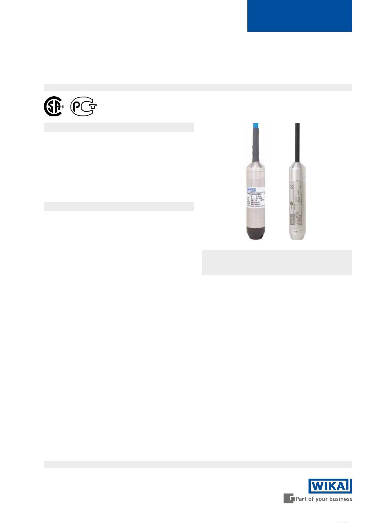
High-performance submersible pressure transmitter
For level measurement
Model LH-10
Applications
■
Level measurement in rivers and lakes
■
Deep well and groundwater monitoring
■
Level measurement in vessel and storage systems
■
Control of sewage lift and pumping stations
■
Monitoring of sewage, settling and stormwater retention
basins
WIKA data sheet PE 81.09
Special features
■
Precise and reliable
■
Integrated temperature measurement (option)
■
Design out of Hastelloy and FEP cable for especially
high resistance (option)
■
Ingress protection IP 68 permanently up to 984 ft (300 m)
water column
Description
For demanding measurement tasks
The model LH-10 submersible pressure transmitter has been
designed for level measurement in contact with the medium
in harsh operating conditions. It oers an accuracy of 0.25 %
and, with an ingress protection of IP 68, is suitable for permanent level measurements up to 984 ft. (300 m) water column.
It oers excellent quality, is reliable and, through a multitude
of options, can be used in all conventional level measurement applications. For instance, integrated temperature
measurement, lightning protection, a Hastelloy
cable are available as options.
case or FEP
Submersible pressure transmitter model LH-10
Fig. left: with PUR cable
Fig. right: in Hastelloy
Robust and reliable
A hermetically-sealed, fully-welded and exceptionally robust
stainless steel case ensures a long service life and permanent sealing.
Specically for external applications, integrated lightning
protection is available, in order to ensure a maximum
operating life in harsh environments.
For the highest media resistance, this submersible pressure
transmitter is available in an optional design out of Hastelloy
and high-resistance FEP cable.
with FEP cable
For the highest accuracy requirements, the optional tempera-
ture measurement enables the compensation of temperature
uctuations in the medium on the measuring result.
Data sheets showing similar products:
Submersible pressure transmitter; model LS-10; see data sheet PE 81.55
High-performance submersible pressure transmitter; model LH-20; see data sheet PE 81.56
Intrinsically safe submersible pressure transmitter; model IL-10; see data sheet PE 81.23
Page 1 of 7WIKA data sheet PE 81.09 ∙ 01/2016
Page 2

Measuring ranges
Relative pressure
bar Measuring range 0 ... 0.1 0 ... 0.16 0 ... 0.25 0 ... 0.4 0 ... 0.6
Overpressure limit 1 1.5 2 2 3
Burst pressure 2 2 2.4 2.4 4
Measuring range 0 ... 1 0 ... 1.6 0 ... 2.5 0 ... 4 0 ... 6
Overpressure limit 5 8 8 10 10
Burst pressure 6 10 10 10 10
Measuring range 0 ... 10 0 ... 16 0 ... 25
Overpressure limit 10 16 25
Burst pressure 10 16 25
inWC Measuring range 0 ... 50 0 ... 100 0 ... 150 0 ... 250
Overpressure limit 750 750 750 1,100
Burst pressure 950 950 950 1,600
psi Measuring range 0 ... 5 0 ... 10 0 ... 15 0 ... 25 0 ... 50
Overpressure limit 30 45 70 120 150
Burst pressure 35 60 90 180 150
Measuring range 0 ... 100 0 ... 150 0 ... 160 0 ... 200 0 ... 300
Overpressure limit 150 150 160 200 300
Burst pressure 150 150 160 200 300
O Measuring range 0 ... 1 0 ... 1.6 0 ... 2.5 0 ... 4 0 ... 6
mH
2
Overpressure limit 10 15 20 20 30
Burst pressure 20 20 24 24 40
Measuring range 0 ... 10 0 ... 16 0 ... 25 0 ... 40 0 .. 60
Overpressure limit 50 80 80 100 100
Burst pressure 60 100 100 100 100
Measuring range 0 ... 100 0 ... 160 0 ... 250
Overpressure limit 100 160 250
Burst pressure
100 160 250
When choosing the FEP cable, only measuring ranges up to 0 ...10 bar, 0 ... 150 psi and 0 ... 100 mH2O are available.
The given measuring ranges are also available in mbar, kPA and MPa.
Output signals
Signal type Signal
Current (2-wire) 4 ... 20 mA
Current (3-wire) 0 ... 20 mA
Voltage (3-wire) DC 0 ... 5 V
DC 0 ... 10 V
DC 0.5 ... 2.5 V
Load in Ω
■
Current output (2-wire):
Voltage supply
Power supply
The power supply depends on the selected output signal.
■
4 ... 20 mA: DC 10 ... 30 V
■
0 ... 20 mA: DC 10 ... 30 V
■
DC 0 ... 5 V: DC 10 ... 30 V
■
DC 0 ... 10 V: DC 14 ... 30 V
■
DC 0.5 ... 2.5 V: DC 5 ... 30 V (suitable for battery opera-
tion)
≤ (power supply - 10 V) / 0.02 A (cable length in m x 0.14 Ω)
■
Current output (3-wire):
≤ (power supply - 3 V) / 0.02 A (cable length in m x 0.14 Ω)
■
Voltage output (3-wire):
> 100 kΩ
Page 2 of 7 WIKA data sheet PE 81.09 ∙ 01/2016
Page 3

Reference conditions
Operating conditions
Temperature
59 ... 77 °F (15 ... 25 °C)
Atmospheric pressure
12.5 ... 15.4 psi (860 ... 1,060 mbar)
Humidity
45 ... 75 % relative
Mounting position
Calibrated in vertical mounting position with pressure
connection facing downwards.
Power supply
DC 24 V
Accuracy data
Accuracy at reference conditions
Measuring ranges < 3.6 psi: ≤ ±0.50 % of span
Measuring ranges ≥ 3.6 psi: ≤ ±0.25 % of span
Including non-linearity, hysteresis, zero oset and end value
deviation (corresponds to measured error per IEC 61298-2).
Non-linearity (per IEC 61298-2)
≤ ±0.2 % of span
Non-repeatability
≤ ±0.1 % of span
Ingress protection (per IEC 60529)
IP 68
Lightning protection (option)
1.5 J per EN 61000-4-5
The option of lightning protection is not available in combination with the Hastelloy
case version.
Permissible temperature ranges
■
Medium
- PUR cable: 14 ... 122 °F (-10 ... +50 °C)
- FEP cable: 14 ... 185 °F (-10 ... +85 °C)
■
Ambient: 14 ... 122 °F (-10 ... +50 °C)
■
Storage: -22 ... 176 °F (-30 ... +80 °C)
Submersion depths
■
Submersible pressure transmitter with FEP cable:
up to 328 ft. (100 m)
■
Submersible pressure transmitter with PUR cable:
up to 984 ft. (300 m)
Maximum tensile strength of the cable
■
FEP cable: up to 350 N without strain relief
up to 500 N with strain relief
■
PUR cable: up to 350 N without strain relief
up to 1,000 N with strain relief
Weight
■
Level probe approx. 0.44 lbs. (200 g)
■
Cable: approx. 0.054 lbs/ft (80 g/m)
■
Additional weight
(accessories): approx. 1.1 lbs. (500 g)
Temperature error at 32 ... 176 °F (0 ... 50 °C)
■
Mean temperature coecient of zero point
Measuring ranges ≤ 0.25 bar: ≤ ±0.4 % of span/10 K
Measuring ranges > 0.25 bar: ≤ ±0.2 % of span/10 K
■
Mean temperature coecient of span
≤ ±0.2 % of span/10 K
Long-term stability at reference conditions
≤ ±0.2 % of span/year
Additional temperature measurement
(option)
The submersible pressure transmitter is optionally available
with a Pt100 measuring element for recording the medium
temperature.
The option of additional temperature measurement is not
available in combination with the Hastelloy
Specications:
■
Pt100 per DIN EN 60751
■
4-wire technology
■
Measuring range -58 ... 185 °F (-50 ... +85 °C)
■
Total current consumption 3 mA
■
Measurement current 1 mA
case version.
Page 3 of 7WIKA data sheet PE 81.09 ∙ 01/2016
Page 4

Process connections
Materials
Standard Thread size
EN 837 G ½ B
- G ¼ female thread (only for
version in Hastelloy
)
Electrical connections
Short-circuit resistance
S
vs. U
-
+
Reverse polarity protection
U+ vs. U
Overvoltage protection
Lightning protection is available as an option; see "Operating
conditions"
Insulation voltage
DC 500 V
-
Wetted parts
Standard Option
Case and sensor Stainless steel 316L Hastelloy
Protection cap PA Stainless steel 316L
Cable PUR FEP
Approvals, directives and certicates
Approvals
■
CSA
■
GOST
For further approvals, see local website
CE conformity
EMC directive 2004/108/EC, EN 61326 emission (group 1,
class B) and immunity (industrial application)
Cable lengths
Available cable lengths
Meter (m) 1.5 3 5 10 15
20 25 30 40 50
60 80 100 200 300
Feet (ft) 5 10 20 30 40
50
Connection diagrams
Cable outlet
2-wire 3-wire
U
+
U
-
S
+
Shield grey grey
brown brown
green green
- white
Pt100 measuring element, 4-wire connection (option)
grey
red
black
yellow
shield, blue
Page 4 of 7 WIKA data sheet PE 81.09 ∙ 01/2016
Page 5

Dimensions in mm
Submersible pressure transmitter model LH-10
with PUR cable with FEP cable with FEP cable, G ½ B, Hastelloy
with FEP cable, G ¼ B, Hastelloy
Page 5 of 7WIKA data sheet PE 81.09 ∙ 01/2016
Page 6

Accessories
Description Order number
Cable strain relief clamp
The cable strain relief clamp enables easy and secure mechanical fastening of the submersible pressure transmitter's cable at the measuring point. It acts as a guide for the cable, in order
to avoid mechanical damage and to reduce the tensile stress.
Additional weight
The additional weight increases the dead weight of the submersible pressure transmitter.
It simplies the lowering into monitoring wells, narrow shafts and deep wells. It eectively
reduces negative environmental inuences on the measuring result from the measured
medium (e.g. turbulent ow).
Stainless steel 316L, approx. 500 g, length (L) 130 mm
Terminal box
The terminal box, with IP 67 ingress protection and watertight ventilation element, provides
a moisture-free electrical termination for the submersible pressure transmitter. It should be
mounted in dry environment or directly in the switch cabinet.
Filter element
The lter element prevents dirt and moisture from entering the venting tube. The watertight
diaphragm also oers a reliable protection for the submersible pressure transmitter.
14052336
14052341
14052339
14052344
Ordering information
Model / Measuring range / Output signal / Temperature measurement / Cable material / Cable length / Case /
Lightning protection / Accessories
Page 6 of 7 WIKA data sheet PE 81.09 ∙ 01/2016
Page 7

Accessories
7.67" [194.82mm]
4.45" [113.03mm]
0.86" [21.84mm]
Dimensions in inches (mm)
0.28”
(7 mm)
3.70”
(94 mm)
0.43”
(11 mm)
5.12”
(130 mm)
6.89”
(175 mm)
Vent tube lter
Part# 7193131
The optional Teon
®
vent
tube lter protects the
vent opening and protects
against the entry of dirt and
moisture.
Cable junction box
Part# 2459686
The cable junction box is
rated NEMA 4 / IP 67 and
is suitable for mounting
outside tanks or shafts or
inside dry control boxes.
Can be wall or DIN rail
mounted.
Cable clamp
Part# 2074257
The cable clamp secures
the cable without bending
or kinking that can damage
the cable vent tube or outer
jacket.
Desiccant drying cartridge part # 9836700
The desiccant drying cartridge helps prevent moisture
buildup inside the vent tube.
7.67” (195mm)
(22mm)
4.45” (113mm)
NPT adapter Part# 1631322
The 316 SS G1/2 adapter replaces the removable protective cap
and converts the threads to 1/2”NPT male external, 1/4” female
internal threads. Includes O-ring.
O-ring
1.23”
(31mm)
1.81”
(46mm)
1/2” NPT male
1/4” NPT female
internal
Conduit adapter Part# 50476114
316 SS 1/2” NPT male cable conduit adapter.
Must be factory installed.
1/2 NPT
27mm
between
ats
1.85” (47mm)
Additional weight
Part# 1524399
The additional weight
replaces the protective
LevelGuard Anti-clog attachment Part # 50077091
1.17”
29.7mm
cap and helps to stabilize
the transmitter in turbulent
conditions. Weight:
approximately 1.1 lb,
5.12”
(130 mm)
© 2016 WIKA Alexander Wiegand SE & Co. KG, all rights reserved.
The specications given in this document represent the state of engineering at the time of publishing.
We reserve the right to make modications to the specications and materials.
Page 7 of 7 WIKA data sheet PE 81.09 ∙ 01/2016
316 SS.
WIKA Instrument, LP
1000 Wiegand Blvd.
Lawrenceville, GA 30043
Tel: 888-WIKA-USA • 770-513-8200
Fax: 770-338-5118
info@wika.com
www.wika.com
The stainless steel LevelGuard
attachment must be factory
installed and calibrated.
01/2016 US
 Loading...