

Page 1

Operating instructions
Betriebsanleitung
Mode d‘emploi
Manual de instrucciones
Shut-o valves and valve manifolds
Models IV10, IV11, IV20, IV21, IV30, IV31, IV50, IV51
Absperrventile und Ventilblöcke
Typen IV10, IV11, IV20, IV21, IV30, IV31, IV50, IV51
Vannes d'arrêt et manifolds
Types IV10, IV11, IV20, IV21, IV30, IV31, IV50, IV51
Válvulas de cierre y manifolds
Modelos IV10, IV11, IV20, IV21, IV30, IV31, IV50, IV51
Model IV10, needle valve Model IV11, multiport valve
Model IV20, block-and-bleed valve Model IV51, 5-valve manifold
EN
DE
FR
ES
Page 2

Operating instructions
EN
Shut-o valves and valve manifolds
Betriebsanleitung
DE
Absperrventile und Ventilblöcke
Mode d‘emploi
FR
Vannes d'arrêt et manifolds
Manual de instrucciones
ES
Válvulas de cierre y manifolds
© 10/2019 WIKA Alexander Wiegand SE & Co. KG
All rights reserved. / Alle Rechte vorbehalten.
WIKA® is a registered trademark in various countries.
WIKA® ist eine geschützte Marke in verschiedenen Ländern.
Prior to starting any work, read the operating instructions!
Keep for later use!
Vor Beginn aller Arbeiten Betriebsanleitung lesen!
Zum späteren Gebrauch aufbewahren!
Lire le mode d‘emploi avant de commencer toute opération !
A conserver pour une utilisation ultérieure !
¡Leer el manual de instrucciones antes de comenzar cualquier trabajo!
¡Guardar el manual para una eventual consulta!
Page 3 - 26
Seite 27 - 50
Page 51 - 75
Página 76 - 98
2
Operating instructions shut-o valves and valve manifolds
14294094.01 10/2019 EN/DE/FR/ES
Page 3

Contents
Contents
1. General information 4
2. Design and function 5
3. Safety 6
4. Transport, packaging and storage 11
5. Commissioning, operation 12
6. Faults 17
7. Maintenance, repair and cleaning 19
8. Dismounting, return and disposal 21
9. Specications 24
EN
14294094.01 10/2019 EN/DE/FR/ES
WIKA operating instructions, shut-o valves and valve manifolds
3
Page 4

1. General information
1. General information
■
The valves described in the operating instructions have been
designed and manufactured using state-of-the-art technology. All
EN
components are subject to stringent quality and environmental
criteria during production. Our management systems are certied to
ISO 9001.
■
These operating instructions contain important information on
handling the product. Working safely requires that all safety
instructions and work instructions are observed.
■
Observe the relevant local accident prevention regulations and
general safety regulations for the product's range of use.
■
The operating instructions are part of the product and must be kept
in the immediate vicinity of the valve and readily accessible to skilled
personnel at any time. Pass the operating instructions on to the next
operator or owner of the product.
■
Skilled personnel must have carefully read and understood the
operating instructions prior to beginning any work.
■
The general terms and conditions contained in the sales
documentation shall apply.
■
Subject to technical modications.
■
Further information:
- Internet address: www.wika.de / www.wika.com
- Relevant data sheets: AC 09.19, AC 09.22, AC 09.23
4 WIKA operating instructions, shut-o valves and valve manifolds
14294094.01 10/2019 EN/DE/FR/ES
Page 5

2. Design and function
2. Design and function
2.1 Functional description
The products described below have built-in bonnets for shutting o,
venting and compensating process pressures for pressure measuring
instruments. The functions of the models described here can be found in
the table on the following page.
Bonnet (standard version)
Gland nut
Seal bush
Spindle tip
1)
Dust cap colour code
Blue: Shut o
Red: Vent
Green: Compensate
T-bar handle
Coloured dust cap
Counter nut
Valve spindle
Sealing packing
Bonnet body
EN
Valve body
Locking pin
1) Optionally other handle designs are available
14294094.01 10/2019 EN/DE/FR/ES
WIKA operating instructions, shut-o valves and valve manifolds
Sealing ring
5
Page 6

2. Design and function / 3. Safety
Model Number of bonnets
Shut o Vent
IV10 1 - -
IV11 1 - -
EN
IV20, IV21 1 1 -
IV30, IV31 2 - 1
IV50, IV51 2 2 1
1) Venting with bonnet, for further venting options (e.g. via vent screw) see data sheet
1)
2.2 Scope of delivery
Cross-check scope of delivery with delivery note.
3. Safety
3.1 Explanation of symbols
DANGER!
... indicates a directly dangerous situation resulting in serious
injury or death, if not avoided.
WARNING!
... indicates a potentially dangerous situation that can result in
serious injury or death, if not avoided.
CAUTION!
... indicates a potentially dangerous situation that can result
in light injuries or damage to equipment or the environment, if
not avoided.
Information
... points out useful tips, recommendations and information for
ecient and trouble-free operation.
Compensate
6 WIKA operating instructions, shut-o valves and valve manifolds
14294094.01 10/2019 EN/DE/FR/ES
Page 7

3. Safety
3.2 Intended use
These valves are used for the separation of measuring instruments from
the process by means of shut-o, venting and pressure compensating
function(s) They are designed for use in applications with clean gaseous
and liquid media that are not highly viscous or crystallising.
The product must only be used with media which are not harmful to
the wetted parts over the entire operating range of the instrument. Any
change in the state of the matter or any decomposition of unstable media
is not permitted.
Only use the product in applications that lie within its technical performance limits (e.g. max. ambient temperature, material compatibility, ...).
→ For performance limits see chapter 9 “Specications”.
Improper handling or operation of the product outside of its technical
specifications requires the instrument to be taken out of service
immediately and inspected by an authorised service engineer.
These valves do not have their own potential ignition source. The
responsibility for the safe use in hazardous areas in accordance with
the accepted standards of technology rests with the operator.
For the reasons mentioned above, these valves are not marked and do
not have their own certification.
The product has been designed and built solely for the intended use
described here, and may only be used accordingly.
The manufacturer shall not be liable for claims of any type based on
operation contrary to the intended use.
EN
3.3 Improper use
Improper use is dened as any application that exceeds the technical
performance limits or is not compatible with the materials.
14294094.01 10/2019 EN/DE/FR/ES
WIKA operating instructions, shut-o valves and valve manifolds
7
Page 8

3. Safety
WARNING!
Injuries through improper use
Improper use of the product can lead to hazardous situations
and injuries.
EN
Any use beyond or dierent to the intended use is considered as
improper use.
3.4 Responsibility of the operator
The product is used in the industrial sector. The operator is therefore
responsible for legal obligations regarding safety at work.
The safety instructions within these operating instructions, as well as the
safety, accident prevention and environmental protection regulations for
the application area must be maintained.
The operator is obliged to maintain the product label in a legible condition.
To ensure safe working on the product, the operating company must
ensure the following:
■
The operating personnel are regularly instructed in all topics
regarding work safety, rst aid and environmental protection
and know the operating instructions and in particular, the safety
instructions contained therein.
■
The operating personnel have read the operating instructions and
taken note of the safety instructions contained therein.
■
The intended use for the application is complied with.
■
Following testing, improper use of the product is excluded.
▶
Refrain from unauthorised modifications to the product.
▶
Do not use the product with abrasive or viscous media.
8 WIKA operating instructions, shut-o valves and valve manifolds
14294094.01 10/2019 EN/DE/FR/ES
Page 9

3. Safety
3.5 Personnel qualication
WARNING!
Risk of injury should qualication be insucient
Improper handling can result in considerable injury and
damage to equipment.
▶
The activities described in these operating instructions
may only be carried out by skilled personnel who have the
qualications described below.
Skilled personnel
Skilled personnel, authorised by the operator, are understood to be
personnel who, based on their technical training, knowledge of measurement and control technology and on their experience and knowledge
of country-specic regulations, current standards and directives, are
capable of carrying out the work described and independently recognising potential hazards.
Operating personnel
The personnel trained by the operator are understood to be personnel
who, based on their education, knowledge and experience, are capable of carrying out the work described and independently recognising
potential hazards.
Special operating conditions require further appropriate knowledge, e.g.
of aggressive media.
3.6 Personal protective equipment
The personal protective equipment is designed to protect the skilled
personnel from hazards that could impair their safety or health during
work. When carrying out the various tasks on and with the product, the
skilled personnel must wear personal protective equipment.
EN
Follow the instructions displayed in the work area regarding
personal protective equipment!
The requisite personal protective equipment must be provided by the
operating company.
14294094.01 10/2019 EN/DE/FR/ES
WIKA operating instructions, shut-o valves and valve manifolds
9
Page 10
3. Safety
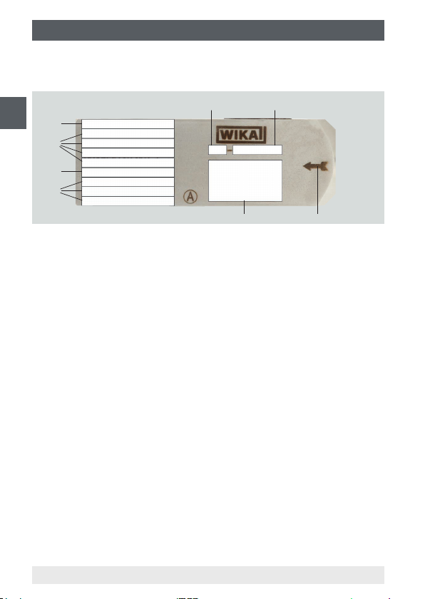
3.7 Labelling, safety marks
Product marking
EN
Article number
Model
ID number
Article description (thread denition, material, etc.)
Permissible operating pressure
Product traceability information (production date, lot number etc.)
Functional diagram
Flow direction
10 WIKA operating instructions, shut-o valves and valve manifolds
14294094.01 10/2019 EN/DE/FR/ES
Page 11

4. Transport, packaging and storage
4. Transport, packaging and storage
4.1 Transport
Check the product for any damage that may have been caused by transport. Obvious damage must be reported immediately.
CAUTION!
With improper transport, a high level of damage to
property can occur.
▶
When unloading packed goods upon delivery as well as
during internal transport, proceed carefully.
▶
With internal transport, observe the instructions in chapter
4.2 “Packaging and storage”.
4.2 Packaging and storage
Do not remove packaging until just before commissioning.
Keep the packaging as it will provide optimum protection during transport
(e.g. change in installation site, sending for repair).
Permissible conditions at the place of storage:
■
Storage temperature: -60 ... +70 °C (-76 ... +158 °F)
■
Humidity: 35 ... 85 % relative humidity (no condensation)
Avoid exposure to the following factors:
■
Direct sunlight or proximity to hot objects
■
Mechanical vibration, mechanical shock (putting it down hard)
■
Soot, vapour, dust and corrosive gases
■
Hazardous environments, ammable atmospheres
EN
Store the product in its original packaging in a location that fulls the
conditions listed above. If the original packaging is not available and if
the product is stored for a prolonged period of time (more than 30 days),
place a bag containing a desiccant inside the packaging.
14294094.01 10/2019 EN/DE/FR/ES
WIKA operating instructions, shut-o valves and valve manifolds
11
Page 12

5. Commissioning, operation
5. Commissioning, operation
Personnel: Skilled personnel
Tools and mounting material:
EN
■
Torque spanner set, open-ended spanner set (17 ... 32 mm)
■
Allen key set
■
Screwdriver
■
Suitable lubricants for sealing elements and bolts
■
Suitable sealing material for threaded connections
Before installation, commissioning and operation, ensure that the appropriate product has been selected in terms of operating conditions, design
and specic measuring conditions.
Only use original parts.
Always observe the mounting and operating instructions of accessories
when commissioning them.
WARNING!
Physical injuries and damage to property and the
environment caused by hazardous media
Upon contact with hazardous media (e.g. with ammable
or toxic substances), harmful media (e.g. corrosive, toxic,
carcinogenic, radioactive), and also with refrigeration plants
and compressors, there is a danger of physical injuries and
damage to property and the environment.
Aggressive media with extremely high temperature and under
high pressure may be present at the product.
▶
For these media, in addition to all standard regulations,
the appropriate existing codes or regulations must also be
followed.
▶
Wear the requisite protective equipment (see chapter 3.6
“Personal protective equipment”).
12 WIKA operating instructions, shut-o valves and valve manifolds
14294094.01 10/2019 EN/DE/FR/ES
Page 13

5. Commissioning, operation
WARNING!
Physical injuries and damage to property and the
environment caused by media escaping under high
pressure
With the pressurisation of the product, as a result of poor
sealing of the connections, media under high pressure can
escape.
Due to the high energy of the media that can escape in
the event of a failure, the possibility of physical injuries and
damage to property exists.
▶
The sealing of the connections must be carried out expertly
and checked for leak tightness.
WARNING!
Physical injuries and damage to property and the
environment caused by improper handling.
Incorrect opening or closing of a valve can lead to the
escape of media.
▶
The operator must be aware of the consequences prior to
changing the state to a specic valve position.
5.1 Mounting
■
When unpacking, check all components for any external damage.
If a return is needed, please follow the instructions given in chapter
8.2 “Return”.
■
Ensure that all unused connections are closed. Plug screws for vent
connections are included in delivery, though not pre-tted.
■
The valve may only be carried by the valve body, not by the handle
■
Check the product marking for correctness (see chapter 3.7 “Labelling, safety marks”).
■
Before mounting, ensure that the process line has been depressurised using the main valve.
■
Mount the measuring instrument at the right connection. Ensure that
the ow direction arrow points from the process connection towards
the measuring instrument.
EN
14294094.01 10/2019 EN/DE/FR/ES
WIKA operating instructions, shut-o valves and valve manifolds
13
Page 14

5. Commissioning, operation
■
Remove the protection caps of the required process connections.
■
Ensure that the sealing faces are clean and do not show any mechanical damage.
■
The correct sealing element must be used for the respective
EN
connection.
Threaded connection
To screw in threaded connections the appropriate tool must only be
applied through the spanner ats provided for this purpose.
The tightening torque is dependent on the process connection and
sealing element used.
Flange connection
Applicable models: IV20, IV21, IV30, IV31, IV50, IV51
Use only the bolts and sealing rings included in delivery:
Models IV20, IV21: 2 bolts, 1 sealing ring
Models IV30, IV31, IV50, IV51: 4 bolts, 2 sealing rings
Instructions for correct process connection mounting can be
found in the relevant standards e.g. IEC 61518
1. Fix the instrument for valve mounting on the workbench.
2. Apply a small amount of grease on the bolts.
3. Apply a small amount of grease to each sealing ring to hold it in
place.
4. Position the valve manifold on the instrument.
5. To ease the mounting for ange connections with 4 screws, place
two centring pins opposite each other.
6. Screw in 2 bolts and tighten them by hand.
7. If applicable, remove the centring pins used before.
8. Then screw in the other 2 bolts and tighten them by hand.
9. Use the torque spanner and tighten the bolts opposite each other
with an initial torque of 34 Nm.
10. Use the torque spanner and tighten the bolts opposite each other
with the nal torque depending on the material.
Final torque for stainless steel: 72 Nm.
Final torque for carbon steel: 87 Nm.
14 WIKA operating instructions, shut-o valves and valve manifolds
14294094.01 10/2019 EN/DE/FR/ES
Page 15

5. Commissioning, operation
5.2 Commissioning and operation
To close the valve, turn the handle in a clockwise direction as far as the
stop. To open the valve, turn the handle anticlockwise as far as the stop.
It will take approximately 4 turns from open to closed and vice versa.
The ow can be controlled by not totally opening/closing the valve.
Please note that the handle may present a slight play and
spin freely up to a quarter turn when in the depressurised
state. This is due to the constructive design.
■
The valve, especially the handle, must not be subjected to any external loading (e.g. use as a climbing aid, support for objects).
■
The handle may only be used by hand; the use of tools is not
accepted.
■
The torque on reaching the valve stop must only be hand-tight.
■
Ensure that all valves of the product are closed prior to opening the
main valve of the process line.
EN
14294094.01 10/2019 EN/DE/FR/ES
WIKA operating instructions, shut-o valves and valve manifolds
15
Page 16
5. Commissioning, operation
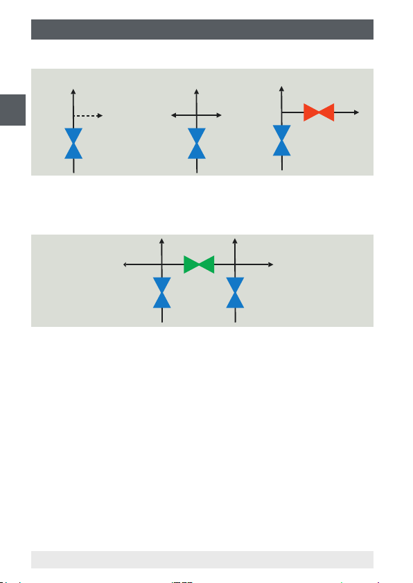
Models IV10, IV11, IV20, IV21
Model IV10 Model IV11 Models IV20, IV21
EN
To avoid pressure surges, open the shut-o valve (blue) slowly.
The pressure is at the instrument connection now.
Models IV30, IV31
1. Open compensating valve (green).
2. To avoid pressure surges, open the shut-o valves (blue) slowly.
The pressure is at the instrument connection now.
3. Close compensating valve (green).
16 WIKA operating instructions, shut-o valves and valve manifolds
14294094.01 10/2019 EN/DE/FR/ES
Page 17

5. Commissioning, operation / 6. Faults
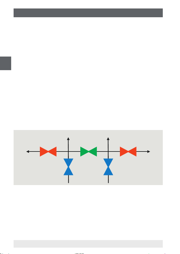
Models IV50, IV51
1. Close vent valves (red).
2. Open compensating valve (green).
3. To avoid pressure surges, open the shut-o valves (blue) slowly.
The pressure is at the instrument connection now.
4. Close compensating valve (green).
6. Faults
The following table contains the most frequent causes of
faults and the necessary countermeasures.
Faults Causes Measures
Dicult handle
operation
Leakage at the
spindle
Lubrication problem due to
unchanged valve position for a
long time period
Defective parts due to
corrosion, process conditions,
age
Overtightened gland nut,
defective sealing packing
Leaking sealing packing See chapter 7.2 “Repair”
Perform a functional test
as described in chapter
“Maintenance” and
7.1
shorten inspection interval
as appropriate
Replace product
Replace product
EN
14294094.01 10/2019 EN/DE/FR/ES
WIKA operating instructions, shut-o valves and valve manifolds
17
Page 18

6. Faults
Faults Causes Measures
No ow or
restricted ow of
process media
EN
CAUTION!
Physical injuries and damage to property and the
environment
If faults cannot be eliminated by means of the listed
measures, the product must be taken out of operation
immediately.
WARNING!
Physical injuries and damage to property and the
environment caused by hazardous media
Upon contact with hazardous media (e.g. oxygen, acetylene,
ammable or toxic substances), harmful media (e.g. corrosive, toxic, carcinogenic, radioactive), and also with refrigeration plants and compressors, there is a danger of physical
injuries and damage to property and the environment.
Should a failure occur, aggressive media with extremely high
temperature and under high pressure or vacuum may be
present at the product.
Valve closed or partially open Ensure that that valve is
Incorrect mounting Ensure that that valve is
Clogging by unsuitable
process media
▶
Ensure that there is no longer any pressure present and
protect against being put into operation accidentally.
▶
Contact the supplier.
▶
If a return is needed, please follow the instructions given in
chapter 8.2 “Return”.
▶
For these media, in addition to all standard regulations,
the appropriate existing codes or regulations must also be
followed.
▶
Wear the requisite protective equipment (see chapter 3.6
“Personal protective equipment”).
open
correctly mounted
Check compatibility of
process media
18 WIKA operating instructions, shut-o valves and valve manifolds
14294094.01 10/2019 EN/DE/FR/ES
Page 19

7. Maintenance, repair and cleaning
7. Maintenance, repair and cleaning
7.1 Maintenance
When used properly, the valves work maintenance-free. They must be
checked within the context of regular maintenance.
Inspection interval
Depending on the process, the ambient conditions and the number of
operations, the required inspection interval may vary from daily to several
weeks.
Recommended inspection interval: ≤ 3 months
Inspection checklist
1. Leak test of the process and instrument connections
2. Leak test between bonnet and valve body
3. Functional test for correct opening and closing
In case the leak test of item 2 fails, proceed with the adjustment of the
sealing packing described below.
7.2 Repair
Adjustment of the sealing packing
This adjustment is required when a leak can be detected at the valve
spindle, directly below the handle, or when during operation there is no
torque or resistance when turning the handle.
1. Loosen the counter nut
2. Increase the packing compression through the gland nut applying a
torque of ≥13 … ≤ 18 Nm (18 … 25 lbs ft)
3. Fix the gland nut with the counter nut
EN
If after the adjustment of the sealing packing the leakage problem
persists, the packing must be returned for repair.
Perfect functioning of the product can only be guaranteed
when original accessories and spare parts are used.
14294094.01 10/2019 EN/DE/FR/ES
WIKA operating instructions, shut-o valves and valve manifolds
19
Page 20

7. Maintenance, repair and cleaning
7.3 Cleaning
CAUTION!
EN
1. Prior to cleaning, properly disconnect the product from the process.
2. Clean the product carefully with a moist cloth.
Physical injuries and damage to property and the
environment
Improper cleaning may lead to physical injuries and damage
to property and the environment. Residual media in the
dismounted product can result in a risk to persons, the
environment and equipment.
▶
Rinse or clean the dismounted product.
▶
Take sucient precautionary measures.
CAUTION!
Damage to property
Improper cleaning may lead to damage to the product!
▶
Do not use any aggressive cleaning agents.
▶
Do not use any hard or pointed objects for cleaning.
20 WIKA operating instructions, shut-o valves and valve manifolds
14294094.01 10/2019 EN/DE/FR/ES
Page 21
8. Dismounting, return and disposal
8. Dismounting, return and disposal
8.1 Dismounting
Before starting the disassembly, you must ensure that the main valve of
the process line is closed.
WARNING!
Risk of burns
During dismounting there is a risk of dangerously hot media
escaping.
▶
Let the product cool down suciently before dismounting it!
WARNING!
Physical injury
When dismounting, there is a danger from aggressive media
and high pressures.
▶
Wear the requisite protective equipment (see chapter 3.6
“Personal protective equipment”).
▶
Observe the information in the material safety data sheet
for the corresponding medium.
▶
Only disconnect the valve once the system has been
depressurised.
WARNING!
Physical injuries and damage to property and the
environment through residual media
Upon contact with hazardous media (e.g. oxygen, acetylene,
ammable or toxic substances), harmful media (e.g. corrosive, toxic, carcinogenic, radioactive), and also with refrigeration plants and compressors, there is a danger of physical
injuries and damage to property and the environment.
▶
Wear the requisite protective equipment (see chapter 3.6
“Personal protective equipment”).
▶
Observe the information in the material safety data sheet
for the corresponding medium.
▶
Before storage of the dismounted product (following
use) wash or clean it, in order to protect persons and the
environment from exposure to residual media.
EN
14294094.01 10/2019 EN/DE/FR/ES
WIKA operating instructions, shut-o valves and valve manifolds
21
Page 22

8. Dismounting, return and disposal
Models IV10, IV11
1. To avoid pressure surges, open the shut-o valve (blue) slowly.
2. In case the valve is equipped with a vent connection, open this
connection with a suitable tool. Remove plug screw/vent screw (if
EN
available).
The valve can be dismounted now.
Models IV20, IV21
1. To avoid pressure surges, open the shut-o valve (blue) slowly.
2. Open the vent connection with a suitable tool. Remove plug screw/
vent screw (if available).
3. Open the vent valve slowly (red) to depressurise the valve.
The valve can be dismounted now.
Models IV30, IV31, IV50, IV51
Vent (red)
Models IV5x only
Shut o
(blue)
Compensate
(green)
Shut o
(blue)
Vent (red)
Models IV5x only
1. Open compensating valve (green).
2. To avoid pressure surges, close the shut-o valves (blue) slowly.
3. Remove plug screws/vent screws (if available).
4. Only for models IV5x: Open vent valves (red) slowly.
The valve can be dismounted now.
22 WIKA operating instructions, shut-o valves and valve manifolds
14294094.01 10/2019 EN/DE/FR/ES
Page 23

8. Dismounting, return and disposal
8.2 Return
Strictly observe the following when shipping the product:
All products delivered to WIKA must be free from any kind of hazardous
substances (acids, bases, solutions, etc.) and must therefore be cleaned
before being returned.
WARNING!
Physical injuries and damage to property and the
environment through residual media
Residual media in the dismounted product can result in a risk
to persons, the environment and equipment.
▶
With hazardous substances, include the material safety
data sheet for the corresponding medium.
▶
Clean the instrument, see chapter 7.2 “Cleaning”.
When returning the product, use the original packaging or a suitable
transport packaging.
Information on returns can be found under the heading
“Service” on our local website.
8.3 Disposal
Incorrect disposal can put the environment at risk.
Dispose of product components and packaging materials in an environ-
mentally compatible way and in accordance with the country-specic
waste disposal regulations.
EN
14294094.01 10/2019 EN/DE/FR/ES
WIKA operating instructions, shut-o valves and valve manifolds
23
Page 24

9. Specications
9. Specications
For the illustrated location of the parts mentioned below, see chapter 2.1
“Functional description”.
EN
Specication
Spindle tip Non-rotating, low-wear
Valve seat Metal seat
Valve bore size 4 mm (0.16 in)
Material Standard Option
Wetted parts
■
Valve body Stainless steel 316/316L
Bonnet body
Spindle tip
Sealing packing PTFE Graphite
Non-wetted parts
Handle Stainless steel 304 Stainless steel 316/316L
Gland nut Stainless steel 316/316L
Counter nut
Valve spindle
Seal bush
Monel 400
■
Hastelloy 276
■
Others on request
24 WIKA operating instructions, shut-o valves and valve manifolds
14294094.01 10/2019 EN/DE/FR/ES
Page 25

9. Specications
Operating conditions
Sealing material Max. permissible operating pressure in bar
at temperature in °C
PTFE 689 bar at 38 °C
276 bar at 204 °C
Graphite 420 bar at 38 °C
209 bar at 538 °C
EN
Sealing material Max. permissible operating pressure in psi
at temperature in °F
PTFE 10,000 psi at 100 °F
4,000 psi at 400 °F
Graphite 6,000 psi at 100 °F
3,030 psi at 1,000 °F
The minimum design temperature is -54 °C (-65 °F).
For permanently low operating temperatures of ≤ -54 °C (≤ -65 °F), a
special design is required.
The following diagram must be used to ensure that the permissible
pressure-temperature rating is met during operation depending on the
sealing material used.
For further specifications see data sheets AC 09.19, AC 09.21,
AC 09.23.
14294094.01 10/2019 EN/DE/FR/ES
WIKA operating instructions, shut-o valves and valve manifolds
25
Page 26

9. Specications
Pressure-temperature diagram
700
(10153)
EN
600
(8702)
500
(7252)
400
(5802)
300
(4351)
200
Pressure in bar (psi)
(2901)
100
(1450)
0
PTFE
Graphite
Temperature in °C (°F)
26 WIKA operating instructions, shut-o valves and valve manifolds
14294094.01 10/2019 EN/DE/FR/ES
Page 27

Inhalt
Inhalt
1. Allgemeines 28
2. Aufbau und Funktion 29
3. Sicherheit 30
4. Transport, Verpackung und Lagerung 35
5. Inbetriebnahme, Betrieb 36
6. Störungen 41
7. Wartung, Instandsetzung und Reinigung 43
8. Demontage, Rücksendung und Entsorgung 45
9. Technische Daten 48
14294094.01 10/2019 EN/DE/FR/ES
WIKA-Betriebsanleitung Absperrventile und Ventilblöcke
DE
27
Page 28

1. Allgemeines
1. Allgemeines
■
Die in der Betriebsanleitung beschriebenen Ventile werden nach
dem aktuellen Stand der Technik konstruiert und gefertigt. Alle
Komponenten unterliegen während der Fertigung strengen Qualitätsund Umweltkriterien. Unsere Managementsysteme sind nach
ISO 9001 zertiziert.
DE
■
Diese Betriebsanleitung gibt wichtige Hinweise zum Umgang mit dem
Produkt. Voraussetzung für sicheres Arbeiten ist die Einhaltung aller
angegebenen Sicherheitshinweise und Handlungsanweisungen.
■
Die für den Einsatzbereich des Produktes geltenden
örtlichen Unfallverhütungsvorschriften und allgemeinen
Sicherheitsbestimmungen einhalten.
■
Die Betriebsanleitung ist Produktbestandteil und muss in
unmittelbarer Nähe des Ventils für das Fachpersonal jederzeit
zugänglich aufbewahrt werden. Betriebsanleitung an nachfolgende
Benutzer oder Besitzer des Produktes weitergeben.
■
Das Fachpersonal muss die Betriebsanleitung vor Beginn aller
Arbeiten sorgfältig durchgelesen und verstanden haben.
■
Es gelten die allgemeinen Geschäftsbedingungen in den
Verkaufsunterlagen.
■
Technische Änderungen vorbehalten.
■
Weitere Informationen:
- Internet-Adresse: www.wika.de / www.wika.com
- Zugehörige Datenblätter: AC 09.19, AC 09.22, AC 09.23
28 WIKA-Betriebsanleitung Absperrventile und Ventilblöcke
14294094.01 10/2019 EN/DE/FR/ES
Page 29

2. Aufbau und Funktion
2. Aufbau und Funktion
2.1 Funktionsbeschreibung
Bei den im Folgenden beschriebenen Produkten sind Ventiloberteile zum
Absperren, Entlüften bzw. Ausgleichen von Prozessdrücken für Druckmessgeräte eingebaut. Die Funktionen der hier beschriebenen Typen ist
der Tabelle auf der Folgeseite zu entnehmen.
Ventiloberteil (Standardausführung)
T-Gristange
Farbige Staubkappe
Stopfbuchsenmutter
Kontermutter
Ventilspindel
Dichtbuchse
Dichtpackung
Ventiloberteil-Gehäuse
Spindelspitze
1)
Farbkennung Staubkappe
Blau: Absperren
Rot: Entlüften
Grün: Ausgleichen
DE
Ventilgehäuse
Verschlussstift
1) Optional sind weitere Griausführungen lieferbar
14294094.01 10/2019 EN/DE/FR/ES
WIKA-Betriebsanleitung Absperrventile und Ventilblöcke
Dichtring
29
Page 30

2. Aufbau und Funktion / 3. Sicherheit
Ty p Anzahl Ventiloberteile
Absperren Entlüften
IV10 1 - -
IV11 1 - -
IV20, IV21 1 1 -
IV30, IV31 2 - 1
DE
IV50, IV51 2 2 1
1) Entlüftung mit Ventiloberteil, weitere Optionen zur Entlüftung (z. B. über Entlüftungsschraube) siehe Datenblatt
1)
Ausgleichen
2.2 Lieferumfang
Lieferumfang mit dem Lieferschein abgleichen.
3. Sicherheit
3.1 Symbolerklärung
GEFAHR!
... weist auf eine unmittelbar gefährliche Situation hin, die
zum Tod oder zu schweren Verletzungen führt, wenn sie nicht
gemieden wird.
WARNUNG!
... weist auf eine möglicherweise gefährliche Situation hin, die
zum Tod oder zu schweren Verletzungen führen kann, wenn
sie nicht gemieden wird.
VORSICHT!
… weist auf eine möglicherweise gefährliche Situation hin, die
zu geringfügigen oder leichten Verletzungen bzw. Sach- und
Umweltschäden führen kann, wenn sie nicht gemieden wird.
Information
... hebt nützliche Tipps und Empfehlungen sowie Informa-
tionen für einen ezienten und störungsfreien Betrieb hervor.
30 WIKA-Betriebsanleitung Absperrventile und Ventilblöcke
14294094.01 10/2019 EN/DE/FR/ES
Page 31

3. Sicherheit
3.2 Bestimmungsgemäße Verwendung
Diese Ventile dienen dazu, Messgeräte mit Hilfe von Abschalt-, Entlüftungs- und Druckausgleichsfunktion(en) vom Prozess zu trennen. Sie
sind konzipiert für den Einsatz in Anwendungen mit sauberen gasför-
migen und üssigen Messstoen, die nicht hochviskos sind und nicht
kristallisieren.
Das Produkt darf nur mit Messstoen betrieben werden, die im gesamten Einsatzbereich des Produktes als unbedenklich für die messstobe-
rührten Teile gelten. Eine Änderung des Aggregatszustandes oder die
Zersetzung instabiler Messstoe ist nicht zulässig.
Das Produkt nur in Anwendungen verwenden, die innerhalb seiner
technischen Leistungsgrenzen liegen (z. B. max. Umgebungstemperatur,
Materialverträglichkeit, ...).
→ Leistungsgrenzen siehe Kapitel 9 „Technische Daten“.
Eine unsachgemäße Handhabung oder ein Betreiben des
Produktes außerhalb der technischen Spezifikationen macht die
sofortige Stilllegung und Überprüfung durch einen autorisierten
Servicemitarbeiter erforderlich.
Diese Armaturen besitzen keine eigene potentielle Zündquelle. Die
Verantwortung für den sicheren Einsatz in explosionsgefährdeten
Bereichen, nach den anerkannten Regeln der Technik, trägt der
Betreiber.
Aus oben genannten Gründen erhalten diese Armaturen keine
Kennzeichnung und haben keine eigene Zertifizierung.
Das Produkt ist ausschließlich für den hier beschriebenen
bestimmungsgemäßen Verwendungszweck konzipiert und konstruiert
und darf nur dementsprechend verwendet werden.
DE
Ansprüche jeglicher Art aufgrund von nicht bestimmungsgemäßer
Verwendung sind ausgeschlossen.
3.3 Fehlgebrauch
Als Fehlgebrauch gilt jede Verwendung, die die technischen Leistungs-
grenzen überschreitet oder mit den Werkstoen unverträglich ist.
14294094.01 10/2019 EN/DE/FR/ES
WIKA-Betriebsanleitung Absperrventile und Ventilblöcke
31
Page 32

3. Sicherheit
WARNUNG!
Verletzungen durch Fehlgebrauch
Fehlgebrauch des Produktes kann zu gefährlichen
Situationen und Verletzungen führen.
▶
Eigenmächtige Umbauten am Produkt unterlassen.
▶
Produkt nicht für abrasive und viskose Messstoffe
DE
Jede über die bestimmungsgemäße Verwendung hinausgehende oder
andersartige Benutzung gilt als Fehlgebrauch.
3.4 Verantwortung des Betreibers
Das Produkt wird im gewerblichen Bereich eingesetzt. Der Betreiber
unterliegt daher den gesetzlichen Pichten zur Arbeitssicherheit.
Die Sicherheitshinweise dieser Betriebsanleitung, sowie die für den
Einsatzbereich des Gerätes gültigen Sicherheits-, Unfallverhütungs- und
Umweltschutzvorschriften einhalten.
Der Betreiber ist verpichtet, das Typenschild lesbar zu halten.
Für ein sicheres Arbeiten am Produkt muss der Betreiber Folgendes
sicherstellen:
■
Bedienpersonal wird regelmäßig in allen zutreenden Fragen von
Arbeitssicherheit, Erste Hilfe und Umweltschutz unterwiesen, sowie
die Betriebsanleitung und insbesondere die darin enthaltenen
Sicherheitshinweise sind bekannt.
■
Bedienpersonal hat Betriebsanleitung gelesen und insbesondere die
darin enthaltenen Sicherheitshinweise zur Kenntnis genommen.
■
Die bestimmungsgemäße Verwendung für den Anwendungsfall wird
eingehalten.
■
Nach Prüfung ist ein Fehlgebrauch des Produktes ausgeschlossen.
verwenden.
32 WIKA-Betriebsanleitung Absperrventile und Ventilblöcke
14294094.01 10/2019 EN/DE/FR/ES
Page 33

3. Sicherheit
3.5 Personalqualikation
WARNUNG!
Verletzungsgefahr bei unzureichender Qualikation
Unsachgemäßer Umgang kann zu erheblichen Personenund Sachschäden führen.
▶
Die in dieser Betriebsanleitung beschriebenen Tätigkeiten
nur durch Fachpersonal nachfolgend beschriebener Quali-
kation durchführen lassen.
Fachpersonal
Das vom Betreiber autorisierte Fachpersonal ist aufgrund seiner
fachlichen Ausbildung, seiner Kenntnisse der Mess- und Regelungstechnik und seiner Erfahrungen sowie Kenntnis der landesspezischen Vorschriften, geltenden Normen und Richtlinien in der Lage, die
beschriebenen Arbeiten auszuführen und mögliche Gefahren selbstständig zu erkennen.
Bedienpersonal
Das vom Betreiber geschulte Personal ist aufgrund seiner Bildung,
Kenntnisse und Erfahrungen in der Lage, die beschriebenen Arbeiten
auszuführen und mögliche Gefahren selbstständig zu erkennen.
Spezielle Einsatzbedingungen verlangen weiteres entsprechendes
Wissen, z. B. über aggressive Messstoe.
3.6 Persönliche Schutzausrüstung
Die persönliche Schutzausrüstung dient dazu, das Fachpersonal gegen
Gefahren zu schützen, die dessen Sicherheit oder Gesundheit bei der
Arbeit beeinträchtigen könnten. Beim Ausführen der verschiedenen
Arbeiten an und mit dem Produkt muss das Fachpersonal persönliche
Schutzausrüstung tragen.
DE
Im Arbeitsbereich angebrachte Hinweise zur persönlichen Schutzausrüstung befolgen!
Die erforderliche persönliche Schutzausrüstung muss vom Betreiber zur
Verfügung gestellt werden.
14294094.01 10/2019 EN/DE/FR/ES
WIKA-Betriebsanleitung Absperrventile und Ventilblöcke
33
Page 34

3. Sicherheit
3.7 Beschilderung, Sicherheitskennzeichnungen
Produktkennzeichnung
DE
Artikelnummer
Typ
ID-Nummer
Artikelbeschreibung (Anschlussgewinde, Werksto usw.)
Zulässiger Betriebsdruck
Informationen zur Rückverfolgbarkeit des Produktes (Herstellungsdatum,
Losnummer usw.)
Funktionsschema
Strömungsrichtung
34 WIKA-Betriebsanleitung Absperrventile und Ventilblöcke
14294094.01 10/2019 EN/DE/FR/ES
Page 35

4. Transport, Verpackung und Lagerung
4. Transport, Verpackung und Lagerung
4.1 Transport
Produkt auf eventuell vorhandene Transportschäden untersuchen. Oensichtliche Schäden unverzüglich mitteilen.
VORSICHT!
Bei unsachgemäßem Transport können Sachschäden in
erheblicher Höhe entstehen.
▶
Beim Abladen der Packstücke bei Anlieferung sowie innerbetrieblichem Transport vorsichtig vorgehen.
▶
Bei innerbetrieblichem Transport die Hinweise unter Kapitel
4.2 „Verpackung und Lagerung“ beachten.
4.2 Verpackung und Lagerung
Verpackung erst unmittelbar vor der Inbetriebnahme entfernen.
Die Verpackung aufbewahren, denn diese bietet bei einem
Transport einen optimalen Schutz (z. B. wechselnder Einbauort,
Reparatursendung).
Zulässige Bedingungen am Lagerort:
■
Lagertemperatur: -60 ... +70 °C (-76 ... +158 °F)
■
Feuchtigkeit: 35 ... 85 % relative Feuchte (keine Betauung)
Folgende Einüsse vermeiden:
■
Direktes Sonnenlicht oder Nähe zu heißen Gegenständen
■
Mechanische Vibration, mechanischer Schock (hartes Aufstellen)
■
Ruß, Dampf, Staub und korrosive Gase
■
Explosionsgefährdete Umgebung, entzündliche Atmosphären
Das Produkt in der Originalverpackung an einem Ort lagern, der die
oben gelisteten Bedingungen erfüllt. Wenn die Originalverpackung nicht
vorhanden ist und bei längerer Einlagerung (mehr als 30 Tage) einen
Beutel mit Trocknungsmittel der Verpackung beilegen.
DE
14294094.01 10/2019 EN/DE/FR/ES
WIKA-Betriebsanleitung Absperrventile und Ventilblöcke
35
Page 36
5. Inbetriebnahme, Betrieb
5. Inbetriebnahme, Betrieb
Personal: Fachpersonal
Werkzeug und Befestigungsmaterial:
■
Drehmomentschlüsselsatz, Gabelschlüsselsatz (17 ... 32 mm)
■
Inbusschlüsselsatz
■
Schraubendreher
DE
■
Geeignete Schmiermittel für Dichtelemente und Schraubbolzen
■
Geeignete Dichtungswerkstoe für Gewindeanschlüsse
Vor Montage, Inbetriebnahme und Betrieb sicherstellen, dass das richtige Produkt hinsichtlich Einsatzbedingungen, Ausführung und spezischen Messbedingungen ausgewählt wurde.
Nur Originalteile verwenden.
Zur Inbetriebnahme von Zubehör unbedingt die jeweilige Montage- und
Betriebsanleitung beachten.
WARNUNG!
Körperverletzungen, Sach- und Umweltschäden durch
gefährliche Messstoe
Bei Kontakt mit gefährlichen Messstoen (z. B. bei brennbaren oder giftigen Stoen), gesundheitsgefährdenden
Messstoen (z. B. ätzend, giftig, krebserregend, radioaktiv)
besteht die Gefahr von Körperverletzungen, Sach- und
Umweltschäden.
Am Produkt können aggressive Messstoe mit extremer
Temperatur und unter hohem Druck anliegen.
▶
Bei diesen Messstoen müssen über die gesamten
allgemeinen Regeln hinaus die einschlägigen Vorschriften
beachtet werden.
▶
Notwendige Schutzausrüstung tragen (siehe Kapitel 3.6
„Persönliche Schutzausrüstung“).
36 WIKA-Betriebsanleitung Absperrventile und Ventilblöcke
14294094.01 10/2019 EN/DE/FR/ES
Page 37

5. Inbetriebnahme, Betrieb
WARNUNG!
Körperverletzungen, Sach- und Umweltschäden durch
unter hohem Druck austretende Messstoe
Bei der Druckbeaufschlagung des Produktes kann aufgr-
und schlechter Abdichtung der Anschlüsse Messsto unter
hohem Druck entweichen.
Durch die hohe Energie des im Fehlerfall austretenden
Messstoes besteht die Gefahr von Körperverletzungen und
Sachschäden.
▶
Die Abdichtung der Anschlüsse muss fachgerecht
ausgeführt und auf Dichtheit überprüft werden.
WARNUNG!
Körperverletzungen, Sach- und Umweltschäden durch
unsachgemäße Handhabung
Falsches Önen oder Schließen eines Ventils kann zum
Austreten von Messstoen führen.
▶
Der Bediener muss sich vor dem Ändern einer bestimmten Ventilstellung der daraus folgenden Konsequenzen
bewusst sein.
5.1 Montage
■
Beim Auspacken alle Teile auf äußerliche Beschädigungen überprüfen. Bei notwendiger Rücksendung die Hinweise unter Kapitel
8.2 „Rücksendung“ beachten.
■
Sicherstellen, dass sämtliche nicht verwendeten Verbindungen
verschlossen sind. Verschlussschrauben für Entlüftungsanschlüsse
im Lieferumfang enthalten, jedoch nicht vormontiert.
■
Das Ventil darf nur am Ventilgehäuse getragen werden, nicht am Gri
■
Überprüfen Sie die Produktkennzeichnung auf Richtigkeit (siehe
Kapitel 3.7 „Beschilderung, Sicherheitskennzeichnung“).
■
Vor der Montage sicherstellen, dass die Prozessleitung mit dem
Hauptventil drucklos gemacht wurde.
■
Das Messgerät am richtigen Anschluss montieren. Sicherstellen,
dass der Durchussrichtungspfeil vom Prozessanschluss in Richtung
Messgerät zeigt.
14294094.01 10/2019 EN/DE/FR/ES
WIKA-Betriebsanleitung Absperrventile und Ventilblöcke
DE
37
Page 38

5. Inbetriebnahme, Betrieb
■
Die Schutzkappen der benötigten Prozessanschlüsse entfernen.
■
Sicherstellen, dass die Dichtächen sauber sind und keine mechanische Beschädigung aufweisen.
■
Für den jeweiligen Anschluss muss das richtige Dichtelement
verwendet werden.
Gewindeanschluss
DE
Zum Einschrauben von Gewindeanschlüssen darf das entsprechende
Werkzeug nur durch die dafür vorgesehenen Schlüsselächen aufgebracht werden.
Das Anzugsdrehmoment ist abhängig vom verwendeten Prozessanschluss und Dichtelement.
Flanschanschluss
Zutreende Typen: IV20, IV21, IV30, IV31, IV50, IV51
Nur die im Lieferumfang enthaltenen Schraubbolzen und Dichtringe
verwenden:
Typen IV20, IV21: 2 Schraubbolzen, 1 Dichtring
Typen IV30, IV31, IV50, IV51: 4 Schraubbolzen, 2 Dichtringe
Anweisungen zur korrekten Montage von
Prozessanschlüssen nden Sie in den entsprechenden
Normen, z. B. IEC 61518
1. Instrument für die Ventilmontage auf der Werkbank befestigen.
2. Eine kleine Menge Fett auf die Schraubbolzen auftragen.
3. Eine kleine Menge Fett auf jeden Dichtring auftragen, damit dieser
nicht verrutschen kann.
4. Den Ventilblock auf dem Gerät positionieren.
5. Zwei Zentrierstifte einander gegenüber einsetzen, um die Montage
der Flanschverbindungen mit 4 Schraubbolzen zu erleichtern.
6. Zwei Schraubbolzen eindrehen und mit der Hand anziehen.
7. Gegebenenfalls die beiden zuvor verwendeten Zentrierstifte entfernen.
8. Dann die beiden anderen Schraubbolzen eindrehen und mit der
Hand anziehen.
9. Mit dem Drehmomentschlüssel die einander gegenüberliegenden
Schraubbolzen mit einem Anfangsdrehmoment von 34 Nm anziehen.
38 WIKA-Betriebsanleitung Absperrventile und Ventilblöcke
14294094.01 10/2019 EN/DE/FR/ES
Page 39

5. Inbetriebnahme, Betrieb
10. Mit Hilfe des Drehmomentschlüssels die einander gegenüberliegenden Schraubbolzen mit dem materialabhängigen Enddrehmoment
nachziehen.
Enddrehmoment für CrNi-Stahl: 72 Nm.
Enddrehmoment für Kohlenstostahl: 87 Nm.
5.2 Inbetriebnahme und Betrieb
Zum Schließen des Ventils den Gri im Uhrzeigersinn bis zum Anschlag
drehen. Zum Önen des Ventils den Gri gegen den Uhrzeigersinn
bis zum Anschlag drehen. Um von der geöneten in die geschlossene
Stellung und umgekehrt zu wechseln, sind ungefähr 4 Umdrehungen
notwendig.
Der Durchuss kann gesteuert werden, indem das Ventil nicht vollständig geönet/geschlossen wird.
Bitte beachten, dass der Gri im drucklosen Zustand ein
leichtes Spiel aufweisen und sich bis zu einer Vierteldrehung
frei drehen kann. Diese Eigenschaft ist konstruktionsbedingt.
■
Das Ventil, insbesondere der Gri, darf von außen keinerlei Belastungen ausgesetzt werden (z. B. Nutzung als Steighilfe, Ablage von
Gegenständen).
■
Der Gri darf nur mit der Hand bedient werden; Werkzeuge dürfen
nicht verwendet werden.
■
Das Drehmoment beim Erreichen des Ventilanschlags darf nur
handfest sein.
■
Sicherstellen, dass alle Ventile des Produkts geschlossen sind, bevor
das Hauptventil der Prozessleitung geönet wird.
DE
14294094.01 10/2019 EN/DE/FR/ES
WIKA-Betriebsanleitung Absperrventile und Ventilblöcke
39
Page 40

5. Inbetriebnahme, Betrieb
Typen IV10, IV11, IV20, IV21
Typ IV10 Typ IV11 Typen IV20, IV21
DE
Zur Vermeidung von Druckstößen das Absperrventil (blau) langsam
önen.
Der Druck ist nun am Geräteanschluss vorhanden.
Typen IV30, IV31
1. Ausgleichsventil önen (grün).
2. Zur Vermeidung von Druckstößen die Absperrventile (blau) langsam
önen.
Der Druck ist nun am Geräteanschluss vorhanden.
3. Ausgleichsventil schließen (grün).
40 WIKA-Betriebsanleitung Absperrventile und Ventilblöcke
14294094.01 10/2019 EN/DE/FR/ES
Page 41

5. Inbetriebnahme, Betrieb / 6. Störungen
Typen IV50, IV51
1. Entlüftungsventile (rot) schließen.
2. Ausgleichsventil önen (grün).
3. Zur Vermeidung von Druckstößen die Absperrventile (blau) langsam
önen.
Der Druck ist nun am Geräteanschluss vorhanden.
4. Ausgleichsventil schließen (grün).
6. Störungen
In der folgenden Tabelle sind die häugsten Fehlerursachen
und erforderliche Gegenmaßnahmen aufgeführt.
Störungen Ursachen Maßnahmen
Gri
schwergängig
Leckage an der
Spindel
14294094.01 10/2019 EN/DE/FR/ES
WIKA-Betriebsanleitung Absperrventile und Ventilblöcke
Schmierproblem aufgrund
einer über längere Zeit
unveränderten Ventilstellung
Defekte Teile aufgrund
von Korrosion,
Prozessbedingungen, Alter
Stopfbuchsenmutter zu stark
angezogen, defekte Dichtpackung
Undichte Dichtpackung Siehe Kapitel 7.2
Funktionstest wie in
Kapitel 7.1 „Wartung
beschrieben durchführen
und eventuell das
Inspektionsintervall
verkürzen
Produkt ersetzen
Produkt ersetzen
„Instandsetzung“
DE
”
41
Page 42

6. Störungen
Störungen Ursachen Maßnahmen
Kein oder
eingeschränkter
Durchuss der
Prozessmedien
DE
Können Störungen mit Hilfe der aufgeführten Maßnahmen
nicht beseitigt werden, Produkt unverzüglich außer Betrieb
setzen.
Bei Kontakt mit gefährlichen Messstoen (z. B. Sauersto,
Acetylen, brennbaren oder giftigen Stoen), gesundheitsgefährdenden Messstoen (z. B. ätzend, giftig, krebserre-
gend, radioaktiv) sowie bei Kälteanlagen, Kompressoren
besteht die Gefahr von Körperverletzungen, Sach- und
Umweltschäden.
Am Produkt können im Fehlerfall aggressive Messstoe mit
extremer Temperatur und unter hohem Druck oder Vakuum
anliegen.
42 WIKA-Betriebsanleitung Absperrventile und Ventilblöcke
Ventil geschlossen oder
teilweise oen
Fehlerhafte Montage Sicherstellen, dass das
Verstopfung durch
ungeeignete Prozessmedien
Sicherstellen, dass das
Ventil geönet ist
Ventil richtig montiert ist
Kompatibilität der
Prozessmedien
überprüfen
VORSICHT!
Körperverletzungen, Sach- und Umweltschäden
▶
Sicherstellen, dass kein Druck mehr anliegt und gegen
versehentliche Inbetriebnahme schützen.
▶
Kontakt mit dem Lieferanten aufnehmen.
▶
Bei notwendiger Rücksendung die Hinweise unter Kapitel
8.2 “Rücksendung” beachten.
WARNUNG!
Körperverletzungen, Sach- und Umweltschäden durch
gefährliche Messstoe
▶
Bei diesen Messstoen müssen über die gesamten
allgemeinen Regeln hinaus die einschlägigen Vorschriften
beachtet werden.
▶
Notwendige Schutzausrüstung tragen (siehe Kapitel 3.6
„Persönliche Schutzausrüstung“).
14294094.01 10/2019 EN/DE/FR/ES
Page 43

7. Wartung, Instandsetzung und Reinigung
7. Wartung, Instandsetzung und Reinigung
7.1 Wartung
Die Ventile arbeiten bei bestimmungsgemäßem Gebrauch wartungsfrei.
Sie sind im Rahmen der regulären Wartung zu überprüfen.
Kontrollintervall
Abhängig von dem Prozess, den Umgebungsbedingungen und der
Anzahl der Betätigungen können die Kontrollintervalle zwischen täglich
oder mehreren Wochen liegen.
Empfohlenes Kontrollintervall: ≤ 3 Monate
Kontrollcheckliste
1. Dichtheitsprüfung der Prozess- und Geräteanschlüsse
2. Dichtheitsprüfung zwischen Ventiloberteil und Ventilgehäuse
3. Funktionstest im Hinblick auf korrektes Önen und Schließen
Bei einem negativen Ergebnis der Dichtheitsprüfung von Punkt 2 die im
Folgenden beschriebene Justage der Dichtpackung durchführen.
7.2 Instandsetzung
Justage der Dichtpackung
Diese Justage ist erforderlich, wenn direkt unter dem Gri eine Leckage
an der Ventilspindel zu erkennen ist oder wenn während des Betriebs
kein Drehmoment oder Widerstand bei Drehung des Gries vorhanden
ist.
1. Kontermutter lösen
2. Packungskompression mit einem Drehmoment von ≥ 13 … ≤ 18 Nm
(18 … 25 lbs ft) auf die Stopfbuchsenmutter erhöhen
3. Stopfbuchsenmutter mit der Kontermutter xieren
DE
Wenn das Problem der Leckage nach der Justage der Dichtpackung
weiterhin besteht, muss eine Rücksendung zur Reparatur beauftragt
werden.
Die Funktion des Produktes kann nur bei Verwendung von
Originalzubehör und Ersatzteilen gewährleistet werden.
14294094.01 10/2019 EN/DE/FR/ES
WIKA-Betriebsanleitung Absperrventile und Ventilblöcke
43
Page 44

7. Wartung, Instandsetzung und Reinigung
7.3 Reinigung
VORSICHT!
Körperverletzungen, Sach- und Umweltschäden
Eine unsachgemäße Reinigung führt zu Körperverletzungen,
Sach- und Umweltschäden. Messstoreste im ausgebauten
DE
1. Vor der Reinigung das Produkt ordnungsgemäß vom Prozess trennen.
2. Das Produkt vorsichtig mit einem feuchten Tuch reinigen.
Produkt können zur Gefährdung von Personen, Umwelt und
Einrichtung führen.
▶
Ausgebautes Produkt spülen bzw. säubern.
▶
Ausreichende Vorsichtsmaßnahmen ergreifen.
VORSICHT!
Sachbeschädigung
Eine unsachgemäße Reinigung führt zur Beschädigung des
Produktes!
▶
Keine aggressiven Reinigungsmittel verwenden.
▶
Keine harten und spitzen Gegenstände zur Reinigung
verwenden.
44 WIKA-Betriebsanleitung Absperrventile und Ventilblöcke
14294094.01 10/2019 EN/DE/FR/ES
Page 45

8. Demontage, Rücksendung und Entsorgung
8. Demontage, Rücksendung und Entsorgung
8.1 Demontage
Vor Beginn der Demontage sicherstellen, dass das Hauptventil der
Prozessleitung geschlossen ist.
WARNUNG!
Verbrennungsgefahr
Beim Ausbau besteht Gefahr durch austretende, gefährlich
heiße Messstoe.
▶
Vor dem Ausbau das Produkt ausreichend abkühlen
lassen!
WARNUNG!
Körperverletzung
Bei der Demontage besteht Gefahr durch aggressive Messst-
oe und hohe Drücke.
▶
Notwendige Schutzausrüstung tragen (siehe Kapitel 3.6
„Persönliche Schutzausrüstung“).
▶
Angaben im Sicherheitsdatenblatt für den entsprechenden
Messsto beachten.
▶
Ventil nur im drucklosen Zustand demontieren.
WARNUNG!
Körperverletzungen, Sach- und Umweltschäden durch
Messstoreste
Bei Kontakt mit gefährlichen Messstoen (z. B. Sauersto,
Acetylen, brennbaren oder giftigen Stoen), gesundheitsgefährdenden Messstoen (z. B. ätzend, giftig, krebserre-
gend, radioaktiv) sowie bei Kälteanlagen, Kompressoren
besteht die Gefahr von Körperverletzungen, Sach- und
Umweltschäden.
▶
Notwendige Schutzausrüstung tragen (siehe Kapitel 3.6
„Persönliche Schutzausrüstung“).
▶
Angaben im Sicherheitsdatenblatt für den entsprechenden
Messsto beachten.
▶
Vor der Einlagerung das ausgebaute Produkt (nach
Betrieb) spülen bzw. säubern, um Personen und Umwelt
vor Gefährdung durch anhaftende Messstoreste zu
14294094.01 10/2019 EN/DE/FR/ES
WIKA-Betriebsanleitung Absperrventile und Ventilblöcke
schützen.
DE
45
Page 46
8. Demontage, Rücksendung und Entsorgung
Typen IV10, IV11
1. Zur Vermeidung von Druckstößen das Absperrventil (blau) langsam
schließen.
2. Wenn das Ventil mit einem Entlüftungsanschluss ausgestattet ist,
diesen mit einem geeigneten Werkzeug önen. Verschlussschraube/
Entlüftungsschraube (falls vorhanden) entfernen.
Das Ventil kann nun demontiert werden.
DE
Typen IV20, IV21
1. Zur Vermeidung von Druckstößen das Absperrventil (blau) langsam
schließen.
2. Den Entlüftungsanschluss mit einem geeigneten Werkzeug önen.
Verschlussschraube/Entlüftungsschraube (falls vorhanden)
entfernen.
3. Entlüftungsventil (rot) langsam önen, um das Ventil drucklos zu
machen.
Das Ventil kann nun demontiert werden.
Typen IV30, IV31, IV50, IV51
Entlüften (rot)
Nur Typen IV5x
Absperren
(blau)
Ausgleichen
(grün)
Absperren
(blau)
Entlüften (rot)
Nur Typen IV5x
1. Ausgleichsventil önen (grün).
2. Zur Vermeidung von Druckstößen die Absperrventile (blau) langsam
schließen.
3. Verschlussschrauben/Entlüftungsschrauben (falls vorhanden)
entfernen.
4. Nur bei den Typen IV5x: Entlüftungsventile (rot) langsam önen.
Das Ventil kann nun demontiert werden.
46 WIKA-Betriebsanleitung Absperrventile und Ventilblöcke
14294094.01 10/2019 EN/DE/FR/ES
Page 47

8. Demontage, Rücksendung und Entsorgung
8.2 Rücksendung
Beim Versand des Produktes unbedingt beachten:
Alle an WIKA gelieferten Produkte müssen frei von Gefahrstoen
(Säuren, Laugen, Lösungen, etc.) sein und sind daher vor der Rücksendung zu reinigen.
WARNUNG!
Körperverletzungen, Sach- und Umweltschäden durch
Messstoreste
Messstoreste im ausgebauten Produkt können zur Gefährdung von Personen, Umwelt und Einrichtung führen.
▶
Bei Gefahrstoen das Sicherheitsdatenblatt für den
entsprechenden Messsto beilegen.
▶
Gerät reinigen, siehe Kapitel 7.2 „Reinigung“.
Zur Rücksendung des Produktes die Originalverpackung oder eine
geeignete Transportverpackung verwenden.
Hinweise zur Rücksendung benden sich in der Rubrik
„Service“ auf unserer lokalen Internetseite.
8.3 Entsorgung
Durch falsche Entsorgung können Gefahren für die Umwelt entstehen.
Produktkomponenten und Verpackungsmaterialien entsprechend den
landesspezischen Abfallbehandlungs- und Entsorgungsvorschriften
umweltgerecht entsorgen.
14294094.01 10/2019 EN/DE/FR/ES
WIKA-Betriebsanleitung Absperrventile und Ventilblöcke
DE
47
Page 48

9. Technische Daten
9. Technische Daten
Eine Abbildung der Positionen der nachfolgend genannten Teile nden
Sie in Kapitel 2.1 „Funktionsbeschreibung“.
Spezikation
Spindelspitze Nichtdrehend, verschleißarm
DE
Ventilsitz Metallsitz
Ventilbohrungsgröße 4 mm (0,16 in)
Werksto Standard Option
Messstoberührte Teile
■
Ventilgehäuse CrNi-Stahl 316/316L
Ventiloberteil-Ge-
häuse
Spindelspitze
Dichtpackung PTFE Graphit
Nicht-messstoberührte Teile
Gri CrNi-Stahl 304 CrNi-Stahl 316/316L
Stopfbuchsenmutter CrNi-Stahl 316/316L
Kontermutter
Ventilspindel
Dichtbuchse
Monel 400
■
Hastelloy 276
■
Weitere auf Anfrage
48 WIKA-Betriebsanleitung Absperrventile und Ventilblöcke
14294094.01 10/2019 EN/DE/FR/ES
Page 49

9. Technische Daten
Einsatzbedingungen
Dichtungswerksto Max. zulässiger Betriebsdruck in bar bei
Temperatur in °C
PTFE 689 bar bei 38 °C
276 bar bei 204 °C
Graphit 420 bar bei 38 °C
209 bar bei 538 °C
DE
Dichtungswerksto Max. zulässiger Betriebsdruck in psi bei
Temperatur in °F
PTFE 10.000 psi bei 100 °F
4.000 psi bei 400 °F
Graphit 6.000 psi bei 100 °F
3.030 psi bei 1.000 °F
Die minimale Auslegungstemperatur beträgt -54 °C (-65 °F).
Für dauerhaft niedrige Betriebstemperaturen von ≤ -54 °C (≤ -65 °F) ist
eine spezielle Ausführung erforderlich.
Mit Hilfe des folgenden Diagramms muss sichergestellt sein, dass
während des Betriebes die zulässige Druck-Temperatur-Zuordnung in
Abhängigkeit des eingesetzten Dichtungswerkstoes eingehalten wird.
Weitere technische Daten siehe Datenblätter AC 09.19, AC 09.21,
AC 09.23.
14294094.01 10/2019 EN/DE/FR/ES
WIKA-Betriebsanleitung Absperrventile und Ventilblöcke
49
Page 50

9. Technische Daten
Druck-Temperatur-Diagramm
700
(10153)
DE
600
(8702)
500
(7252)
400
(5802)
300
(4351)
Druck in bar (psi)
200
(2901)
100
(1450)
0
PTFE
Graphit
Temperatur in °C (°F)
50 WIKA-Betriebsanleitung Absperrventile und Ventilblöcke
14294094.01 10/2019 EN/DE/FR/ES
Page 51

Sommaire
Sommaire
1. Généralités 52
2. Conception et fonction 53
3. Sécurité 54
4. Transport, emballage et stockage 59
5. Mise en service, utilisation 60
6. Dysfonctionnements 65
7. Entretien, réparation et nettoyage 67
8. Démontage, retour et mise au rebut 69
9. Spécications 72
FR
14294094.01 10/2019 EN/DE/FR/ES
Mode d'emploi WIKA pour vannes d'arrêt et manifolds
51
Page 52

1. Généralités
1. Généralités
■
Les vannes décrites dans le mode d'emploi sont conçues et
fabriquées selon les dernières technologies en vigueur. Tous les
composants sont soumis à des exigences environnementales et de
qualité strictes durant la fabrication. Nos systèmes de gestion sont
certiés selon ISO 9001.
■
Ce mode d'emploi donne des indications importantes concernant
l'utilisation du produit. Il est possible de travailler en toute sécurité
FR
avec ce produit en respectant toutes les consignes de sécurité et
d'utilisation.
■
Respecter les prescriptions locales de prévention contre les
accidents et les prescriptions générales de sécurité en vigueur pour
le domaine d'application du produit.
■
Le mode d'emploi fait partie de l'instrument et doit être conservé à
proximité immédiate de la vanne et accessible à tout moment pour
le personnel qualié. Coner le mode d'emploi à l'utilisateur ou
propriétaire ultérieur du produit.
■
Le personnel qualié doit, avant de commencer toute opération, avoir
lu soigneusement et compris le mode d'emploi.
■
Les conditions générales de vente mentionnées dans les documents
de vente s'appliquent.
■
Sous réserve de modications techniques.
■
Pour obtenir d'autres informations :
- Consulter notre site Internet : www.wika.fr
- Fiches techniques correspondantes : AC 09.19, AC 09.22,
AC 09.23
52 Mode d'emploi WIKA pour vannes d'arrêt et manifolds
14294094.01 10/2019 EN/DE/FR/ES
Page 53

2. Conception et fonction
2. Conception et fonction
2.1 Description fonctionnelle
Les produits décrits ci-dessous sont munis de robinets intégrés
permettant la fermeture, la mise à l'atmosphère et la compensation des
pressions de process pour des instruments de mesure de pression. Vous
trouverez les fonctions des types décrits ici dans le tableau à la page
suivante.
Chapeau de vanne (version standard)
Poignée en T
Capuchon anti-poussière de
Ecrou de presse-étoupe
Contre-écrou
Tige de vanne
Presse-étoupe d'étanchéité
Garniture d'étanchéité
Corps du chapeau de vanne
Extrémité de la tige
1)
couleur
Corps
Broche de verrouillage
1) En option, d'autres exécutions de poignée sont disponibles
14294094.01 10/2019 EN/DE/FR/ES
Mode d'emploi WIKA pour vannes d'arrêt et manifolds
Code couleur du capuchon
anti poussière
Bleu : fermeture
Rouge : mise à l'atmosphère
Vert : compenser
Joint d'étanchéité
FR
53
Page 54

2. Conception et fonction / 3. Sécurité
Type Nombre de robinets
Fermeture Mise à
l'atmosphère
IV10 1 - -
IV11 1 - -
IV20, IV21 1 1 -
IV30, IV31 2 - 1
IV50, IV51 2 2 1
FR
1) Mise à l'atmosphère avec robinet, pour d'autres options de mise à l'atmosphère, (par exemple par vis de mise
à l'atmosphère), voir che technique
1)
Compenser
2.2 Détail de la livraison
Comparer le détail de la livraison avec le bordereau de livraison.
3. Sécurité
3.1 Explication des symboles
DANGER !
... indique une situation dangereuse pouvant entraîner la mort
ou des blessures graves si elle n'est pas évitée.
AVERTISSEMENT !
… indique une situation présentant des risques susceptibles
de provoquer la mort ou des blessures graves si elle n'est pas
évitée.
ATTENTION !
… indique une situation potentiellement dangereuse et
susceptible de provoquer de légères blessures ou des
dommages matériels et pour l'environnement si elle n'est pas
évitée.
Information
... met en exergue les conseils et recommandations utiles de
même que les informations permettant d'assurer un fonction-
nement ecace et normal.
54 Mode d'emploi WIKA pour vannes d'arrêt et manifolds
14294094.01 10/2019 EN/DE/FR/ES
Page 55

3. Sécurité
3.2 Utilisation conforme à l'usage prévu
Ces vannes sont utilisées pour isoler des instruments de mesure du
process au moyen de fonctions de fermeture, de mise à l'atmosphère et
de compensation de pression. Elles sont conçues pour un emploi dans
des applications avec des uides gazeux et liquides propres qui ne sont
pas hautement visqueux ni cristallisants.
Le produit doit seulement être utilisé avec des uides qui ne sont pas
nocifs pour les parties en contact avec le uide sur la totalité de la plage
de fonctionnement de l'instrument. Tout changement d'état de la matière
ou toute décomposition de uides instables sont interdits.
Utiliser le produit uniquement dans des applications qui se trouvent dans
les limites de ses performances techniques (par exemple température
ambiante maximale, compatibilité de matériau, ...).
→ Pour les limites de performance, voir chapitre 9 “Spécications”.
En cas d'utilisation non conforme ou de fonctionnement du produit en
dehors des spécifications techniques, un arrêt et contrôle doivent être
immédiatement effectués par un collaborateur autorisé du service.
Ces vannes n'ont pas leur source d'ignition de potentiel propre. La
responsabilité d'un usage en toute sécurité en zone explosive en
conformité avec les standards technologiques reconnus incombe à
l'opérateur.
Pour les raisons mentionnées ci-dessus, ces vannes ne sont pas
marquées et ne possèdent pas de certification propre.
Le produit est conçu et construit exclusivement pour une utilisation
conforme à l'usage prévu décrit ici, et ne doit être utilisé qu'à cet effet.
FR
Aucune réclamation ne peut être recevable en cas d'utilisation non
conforme à l'usage prévu.
3.3 Utilisation inappropriée
On dénit un usage impropre comme étant toute application qui excède
les limites techniques de performance ou étant incompatible avec les
matériaux.
14294094.01 10/2019 EN/DE/FR/ES
Mode d'emploi WIKA pour vannes d'arrêt et manifolds
55
Page 56

3. Sécurité
AVERTISSEMENT !
Blessures causées par une utilisation inappropriée
Une utilisation inappropriée du produit peut conduire à des
situations dangereuses et à des blessures.
▶
S'abstenir de modifications non autorisées sur le produit.
▶
Ne pas utiliser le produit avec un fluide abrasif ou
visqueux.
Toute utilisation diérente ou au-delà de l'utilisation prévue est
considérée comme inappropriée.
FR
3.4 Responsabilité de l'opérateur
Le produit est prévu pour un usage dans le domaine industriel.
L'opérateur est de ce fait responsable des obligations légales en matière
de sécurité du travail.
Les instructions de sécurité de ce mode d'emploi comme les réglementations liées à la sécurité, à la prévention des accidents et à la protection
de l'environnement pour le domaine d'application doivent être respectées.
L'opérateur doit s'assurer que la plaque signalétique reste lisible.
An de travailler en toute sécurité sur le produit, la société exploitante
doit s'assurer que les points suivants sont respectés :
■
Le personnel opérationnel est formé à intervalles réguliers sur tous
les sujets concernant la sécurité du travail, les premiers secours et
la protection de l'environnement et il connaît le mode d'emploi et
particulièrement les consignes de sécurité contenues dans celui-ci.
■
Le personnel opérationnel doit avoir lu le mode d'emploi et pris note
des instructions de sécurité qu'il contient.
■
L'utilisation prévue de l'application a été respectée.
■
A la suite des essais, une utilisation impropre du produit est exclue.
56 Mode d'emploi WIKA pour vannes d'arrêt et manifolds
14294094.01 10/2019 EN/DE/FR/ES
Page 57

3. Sécurité
3.5 Qualication du personnel
AVERTISSEMENT !
Danger de blessure en cas de qualication insusante
Une utilisation non conforme peut entraîner d'importants
dommages corporels et matériels.
▶
Les opérations décrites dans ce mode d'emploi ne doivent
être eectuées que par un personnel ayant la qualication
décrite ci-après.
Personnel qualié
Le personnel qualié, autorisé par l'opérateur, est, en raison de sa
formation spécialisée, de ses connaissances dans le domaine de
l'instrumentation de mesure et de régulation et de son expérience,
de même que de sa connaissance des réglementations nationales et
des normes en vigueur, en mesure d'eectuer les travaux décrits et
d'identier de façon autonome les dangers potentiels.
Personnel opérationnel
Le personnel formé par l'opérateur est, en raison de sa formation et de
son expérience en mesure d'eectuer les travaux décrits et de reconnaître de façon autonome les dangers potentiels.
Les conditions d'utilisation spéciales exigent également une connaissance adéquate, par ex. des liquides agressifs.
3.6 Equipement de protection individuelle
L'équipement de protection individuelle sert à protéger le personnel
qualié contre les dangers pouvant entraver la sécurité et la santé de ce
dernier durant le travail. Le personnel qualié doit porter l'équipement
de protection individuelle lors de l'exécution des diérents travaux sur et
avec le produit.
FR
Respecter les indications concernant l'équipement de protection
individuelle dans la zone de travail !
L'équipement de protection individuelle requis doit être mis à disposition
par l'utilisateur.
14294094.01 10/2019 EN/DE/FR/ES
Mode d'emploi WIKA pour vannes d'arrêt et manifolds
57
Page 58

3. Sécurité
3.7 Etiquetage, marquages de sécurité
Marquage de produit
FR
Numéro d'article
Type
Numéro d'identication
Description d'article (dénition du letage, matériau, etc.)
Pression de service admissible
Informations concernant la traçabilité du produit (date de production, numéro de lot, etc.)
Schéma de fonctionnement
Sens de l'écoulement
58 Mode d'emploi WIKA pour vannes d'arrêt et manifolds
14294094.01 10/2019 EN/DE/FR/ES
Page 59

4. Transport, emballage et stockage
4. Transport, emballage et stockage
4.1 Transport
Vérier si le produit a été endommagé pendant le transport. Communiquer immédiatement les dégâts constatés.
ATTENTION !
Un transport inapproprié peut donner lieu à des
dommages importants.
▶
Lors du déchargement des colis à la livraison comme lors
du transport des colis en interne après réception, il faut
procéder avec soin.
▶
Lors du transport en interne après réception, observer les
instructions du chapitre 4.2 “Emballage et stockage”.
4.2 Emballage et stockage
N'enlever l'emballage qu'avant la mise en service.
Conserver l'emballage, celui-ci ore, lors d'un transport, une protection
optimale (par ex. changement de lieu d'utilisation, renvoi pour
réparation).
Conditions admissibles sur le lieu de stockage :
■
Température de stockage : 0 ... 70 °C
■
Humidité : 35 ... 85 % d'humidité relative (sans condensation)
Eviter les inuences suivantes :
■
Lumière solaire directe ou proximité d'objets chauds
■
Vibrations mécaniques, chocs mécaniques (mouvements brusques
en le posant)
■
Suie, vapeur, poussière et gaz corrosifs
■
Environnements dangereux, atmosphères inammables
FR
Conserver le produit dans l'emballage original dans un endroit qui satisfait aux conditions susmentionnées. Si l'emballage d'origine n'est pas
disponible et si le produit est entreposé pendant une période prolongée
(plus de 30 jours), mettre également un sachet absorbeur d'humidité
dans l'emballage.
14294094.01 10/2019 EN/DE/FR/ES
Mode d'emploi WIKA pour vannes d'arrêt et manifolds
59
Page 60

5. Mise en service, utilisation
5. Mise en service, utilisation
Personnel : personnel qualié
Outillage et matériel d'installation
■
Jeu de clés dynamométriques, jeu de clés plates (17 ... 32 mm)
■
Jeu de clés à six pans creux
■
Tournevis
■
Lubriants adéquats pour les éléments d'étanchéité et les boulons
■
Matériau d'étanchéité adéquat pour les raccords letés
FR
Avant le montage, la mise en service et le fonctionnement, s'assurer que
le produit a été choisi de façon adéquate, en ce qui concerne l'étendue
de mesure, la version et les conditions de mesure spéciques.
Utiliser uniquement des pièces d'origine.
Toujours respecter le manuel d'installation et le mode d'emploi des
accessoires avant de les mettre en service.
AVERTISSEMENT !
Blessures physiques et dommages aux équipements et
à l'environnement causés par un uide dangereux
Lors du contact avec un uide dangereux (par exemple
substances inammables ou toxiques), un uide nocif (par
exemple corrosif, toxique, cancérigène, radioactif), et égale-
ment avec des installations frigoriques et des compresseurs,
il y a un danger de blessures physiques et de dommages aux
équipements et à l'environnement.
Des uides agressifs à une température extrême et sous une
pression élevée peuvent être présents au niveau du produit.
▶
Pour ces uides, les codes et directives appropriés
existants doivent être observés en plus des régulations
standard.
▶
Porter les équipements de protection requis (voir chapitre
3.6 “Equipement de protection individuelle”).
60 Mode d'emploi WIKA pour vannes d'arrêt et manifolds
14294094.01 10/2019 EN/DE/FR/ES
Page 61

5. Mise en service, utilisation
AVERTISSEMENT !
Blessures physiques et dommages aux équipements et
à l'environnement causés par un uide qui s'échapperait
sous haute pression
Avec la pressurisation du produit, si l'étanchéité des raccords
est insusante, des uides sous haute pression peuvent
s'échapper.
En raison de la haute énergie du uide qui pourrait s'échapper en cas de défaillance, il existe un danger de blessures
physiques et de dommages au matériel.
▶
L'étanchéité des raccords doit être eectuée par des
spécialistes et vériée pour voir s'il y a des fuites.
AVERTISSEMENT !
Blessures physiques et dommages aux équipements
et à l'environnement causés par une manipulation
incorrecte.
L'ouverture ou la fermeture incorrecte d'une vanne peut
provoquer une fuite de uide.
▶
L'opérateur doit être conscient des conséquences avant
de changer l'état et de passer à une position de vanne
spécique.
5.1 Installation
■
Lors du déballage, vérier si les composants ne présentent aucune
détérioration externe visible. S'il est nécessaire de retourner
l'instrument au fabricant, prière de respecter les indications mention-
nées au chapitre 8.2 “Return”.
■
Assurez-vous que toutes les connexions non-utilisées sont
bien fermées. Les vis de blocage pour les raccords de mise à
l'atmosphère sont incluses dans la livraison, mais ne sont pas
pré-installées.
■
La vanne doit être transportée seulement par le corps de vanne et
non par la poignée
■
Vérier si le marquage de produit est correct (voir chapitre 3.7
“Etiquetage, marquages de sécurité”).
■
Avant l'installation, il faut s'assurer que la ligne de process a bien été
dépressurisée au moyen de la vanne principale.
14294094.01 10/2019 EN/DE/FR/ES
Mode d'emploi WIKA pour vannes d'arrêt et manifolds
FR
61
Page 62

5. Mise en service, utilisation
■
Installer l'instrument de mesure sur le bon raccord. Assurez-vous que
la èche de direction d'écoulement provenant du raccord process
pointe bien vers l'instrument de mesure.
■
Retirer les couvercles de protection des raccords process requis.
■
S'assurer que les surfaces d'étanchéité sont propres et ne présentent
aucun dommage mécanique.
■
L'élément d'étanchéité correct doit être utilisé pour la connexion en
question.
Raccord leté
FR
Pour visser des raccords letés, l'outil adéquat ne doit être appliqué que
par les surfaces de clé prévues à cet eet.
Le couple de serrage dépend du raccord process et de l'élément
d'étanchéité choisis.
Connexion par bride
Types applicables : IV20, IV21, IV30, IV31, IV50, IV51
Utiliser seulement les boulons et les bagues d'étanchéité inclus dans la
livraison :
Models IV20, IV21 : 2 boulons, 1 bague de serrage
Types IV30, IV31, IV50, IV51 : 4 boulons, 2 bagues de serrage
Les instructions pour une installation correcte d'un raccord
process se trouvent dans les normes en question, par
exemple CEI 61518
1. Fixer l'instrument sur l'établi pour monter la vanne.
2. Appliquer un peu de graisse sur les boulons.
3. Appliquer un peu de graisse sur chaque bague d'étanchéité pour la
maintenir en place.
4. Positionner le bloc de vannes sur l'instrument.
5. Pour faciliter l'installation pour des raccords à bride à 4 vis, placer
deux goujons de centrage l'un en face de l'autre.
6. Visser 2 boulons et les serrer à la main.
7. Le cas échéant, retirer les goujons de centrage précédemment
utilisés.
8. Visser alors les deux autres boulons et les serrer à la main.
9. Utiliser la clé dynamométrique pour serrer les boulons l'un en face de
l'autre avec un couple initial de 34 Nm.
62 Mode d'emploi WIKA pour vannes d'arrêt et manifolds
14294094.01 10/2019 EN/DE/FR/ES
Page 63

5. Mise en service, utilisation
10. Utiliser la clé dynamométrique pour serrer les boulons l'un en face de
l'autre avec le couple nal dépendant du matériau.
Couple nal pour l'acier inox : 72 Nm.
Couple nal pour l'acier au carbone : 87 Nm.
5.2 Mise en service et utilisation
Pour fermer la vanne, tourner la poignée dans le sens des aiguilles d'une
montre jusqu'à la butée. Pour ouvrir la vanne, tourner la poignée dans le
sens contraire à celui des aiguilles d'une montre jusqu'à la butée. Cela
prendra environ 4 tours entre la position ouverte et la position fermée et
vice versa.
Le ux peut être contrôlé en n'ouvrant ou ne fermant pas complètement
la vanne.
Il faut avoir à l'esprit que la poignée peut avoir un léger jeu
et tourner librement jusqu'à un quart de tour lorsqu'on est en
état dépressurisé. Ceci est dû à sa construction.
■
La vanne, et tout particulièrement la poignée, ne doit pas être soumise à une quelconque contrainte extérieure (par exemple être utilisée
comme aide pour grimper, comme support pour des objets).
■
Il ne faut utiliser la poignée qu'à la main, il est interdit d'employer des
outils.
■
Le couple lorsqu'on atteint la butée de vanne doit être seulement
serré à la main.
■
Il faut s'assurer que toutes les vannes du produit sont fermées avant
d'ouvrir la vanne principale de la ligne de process.
FR
14294094.01 10/2019 EN/DE/FR/ES
Mode d'emploi WIKA pour vannes d'arrêt et manifolds
63
Page 64

5. Mise en service, utilisation
Types IV10, IV11, IV20, IV21
Type IV10 Type IV11 Types IV20, IV21
FR
Pour éviter des pics de pression, ouvrir lentement la vanne d'arrêt
(bleue).
La pression se trouve maintenant sur le raccord de l'instrument.
Types IV30, IV31
1. Ouvrir la vanne de compensation (verte).
2. Pour éviter des pics de pression, ouvrir lentement les vannes d'arrêt
(bleues).
La pression se trouve maintenant sur le raccord de l'instrument.
3. Fermer la vanne de compensation (verte).
Types IV50, IV51
64 Mode d'emploi WIKA pour vannes d'arrêt et manifolds
14294094.01 10/2019 EN/DE/FR/ES
Page 65

5. Mise en service, ... / 6. Dysfonctionnements
1. Fermer les vannes de mise à l'atmosphère (rouges).
2. Ouvrir la vanne de compensation (verte).
3. Pour éviter des pics de pression, ouvrir lentement les vannes d'arrêt
(bleues).
La pression se trouve maintenant sur le raccord de l'instrument.
4. Fermer la vanne de compensation (verte).
6. Dysfonctionnements
Le tableau suivant contient les causes de
dysfonctionnements les plus fréquentes et les contremesures nécessaires.
FR
Dysfonctionne-
Raisons Mesures
ments
La poignée
est dicile à
manipuler
Fuite au niveau de
la tige de l'aiguille
Pas de débit ou
débit restreint de
uide de process
14294094.01 10/2019 EN/DE/FR/ES
Mode d'emploi WIKA pour vannes d'arrêt et manifolds
Problème de lubrication
causé par une position de
vanne inchangée pendant une
longue période
Pièces défectueuses dues à
la corrosion, aux conditions de
process, à l'âge
Ecrou du presse-étoupe trop
serré, garniture d'étanchéité
défectueuse
Garniture d'étanchéité qui fuit Voir chapitre 7.2
Vanne fermée ou partiellement
ouverte
Montage incorrect S'assurer que la vanne est
Blocage dû à des uides de
process inadaptés
Eectuer un test de
fonctionnement comme
décrit au chapitre 7.1
“Entretien” et raccourcir
l'intervalle d'inspection
comme il convient
Remplacer le produit
Remplacer le produit
“Réparation”
S'assurer que la vanne est
ouverte
montée correctement
Vérier la compatibilité
des uides de process
65
Page 66

6. Dysfonctionnements
ATTENTION !
Blessures physiques, dommages aux équipements et à
l'environnement
Si les défauts ne peuvent pas être éliminés au moyen des
mesures listées, le produit doit être mis hors service immédiatement.
▶
Assurez-vous qu'il n'y a plus aucune pression présente et
empêchez toute remise en marche accidentelle.
▶
Contacter le fabricant.
▶
FR
S'il est nécessaire de retourner l'instrument au fabricant,
prière de respecter les indications mentionnées au chapitre
8.2 “Return”.
AVERTISSEMENT !
Blessures physiques et dommages aux équipements et
à l'environnement causés par un uide dangereux
Lors du contact avec un uide dangereux (par exemple
oxygène, acétylène, substances inammables ou toxiques),
un uide nocif (par exemple corrosif, toxique, cancérigène,
radioactif), et également avec des installations frigoriques
et des compresseurs, il y a un danger de blessures et de
dommages aux équipements et à l'environnement.
En cas d'erreur, des uides agressifs peuvent être présents
à une température extrême et sous une pression élevée ou
sous vide au niveau du produit.
▶
Pour ces uides, les codes et directives appropriés
existants doivent être observés en plus des régulations
standard.
▶
Porter les équipements de protection requis (voir chapitre
3.6 “Equipement de protection individuelle”).
66 Mode d'emploi WIKA pour vannes d'arrêt et manifolds
14294094.01 10/2019 EN/DE/FR/ES
Page 67

7. Entretien, réparation et nettoyage
7. Entretien, réparation et nettoyage
7.1 Entretien
Les vannes fonctionnent sans entretien lorsqu'elles sont utilisées correc-
tement. Elles doivent être vériées dans le cadre d'un entretien régulier.
Intervalle d'inspection
En fonction du process, des conditions ambiantes et du nombre
d'opérations, l'intervalle d'inspection requis peut varier entre quotidiennement et plusieurs semaines.
Intervalle d'inspection recommandé : ≤ 3 mois
Liste de contrôle pour l'inspection
1. Test d'étanchéité des raccords d'instrument et de process
2. Test d'étanchéité entre le chapeau de vanne et le corps de vanne
3. Test de fonctionnement pour une ouverture et une fermeture correc-
tes
Dans le cas où le test de l'élément 2 échouerait, eectuer le réglage de
la garniture d'étanchéité décrit ci-dessous.
7.2 Réparation
Réglage de la garniture d'étanchéité
Ce réglage est nécessaire lorsque'une fuite a pu être détectée sur la tige
de l'aiguille, juste en-dessous de la poignée, ou si, lors du fonctionnement, il n'y pas de couple ni de résistance lorsqu'on tourne la poignée.
1. Desserrer le contre-écrou
2. Augmenter la compression de la garniture au moyen de l'écrou
du presse-étoupe en appliquant un couple ≥ 13 … ≤ 18 Nm
(18 … 25 lbs ft)
3. Fixer l'écrou du presse-étoupe avec le contre-écrou
FR
Si, après le réglage de la garniture d'étanchéité, le problème de fuites
persiste, il faut renvoyer la garniture pour réparation.
Le bon fonctionnement du produit peut uniquement être
garanti si des accessoires et pièces de rechange originaux
sont utilisés.
14294094.01 10/2019 EN/DE/FR/ES
Mode d'emploi WIKA pour vannes d'arrêt et manifolds
67
Page 68

7. Entretien, réparation et nettoyage
7.3 Nettoyage
ATTENTION !
Blessures physiques, dommages aux équipements et à
l'environnement
Un nettoyage inapproprié peut conduire à des blessures
physiques et à des dommages aux équipements ou à l'envi-
ronnement. Les restes de uides se trouvant sur les produits
démontés peuvent mettre en danger les personnes, l'environ-
FR
1. Avant le nettoyage, débrancher correctement le produit du processus.
2. Nettoyer le produit soigneusement avec un chion humide.
nement ainsi que l'installation.
▶
Rincer ou nettoyer avec des moyens appropriés le produit
qui a été démonté.
▶
Prendre des mesures de sécurité susantes.
ATTENTION !
Dommages aux équipements
Un nettoyage inapproprié peut endommager le produit !
▶
Ne pas utiliser de détergents agressifs.
▶
Ne pas utiliser d'objets pointus ou durs pour le nettoyage.
68 Mode d'emploi WIKA pour vannes d'arrêt et manifolds
14294094.01 10/2019 EN/DE/FR/ES
Page 69
8. Démontage, retour et mise au rebut
8. Démontage, retour et mise au rebut
8.1 Démontage
Avant de commencer le démontage, vous devez vous assurer que la
vanne principale du process est bien fermée.
AVERTISSEMENT !
Danger de brûlures
Durant le démontage, il y a un danger lié à l'échappement de
uides dangereusement chauds.
▶
Laisser le produit refroidir susamment avant de le démonter !
AVERTISSEMENT !
Blessures physiques
Lors du démontage, le danger peut provenir de uides agressifs et de pressions élevées.
▶
Porter les équipements de protection requis (voir chapitre
3.6 “Equipement de protection individuelle”).
▶
Observer les informations de la che de données de
sécurité du uide correspondant.
▶
Déconnecter la vanne seulement si le système a été mis
hors pression.
AVERTISSEMENT !
Blessures physiques et dommages aux équipements et à
l'environnement liés aux résidus de uides
Lors du contact avec un uide dangereux (par exemple
oxygène, acétylène, substances inammables ou toxiques),
un uide nocif (par exemple corrosif, toxique, cancérigène,
radioactif), et également avec des installations frigoriques
et des compresseurs, il y a un danger de blessures et de
dommages aux équipements et à l'environnement.
▶
Porter les équipements de protection requis (voir chapitre
3.6 “Equipement de protection individuelle”).
▶
Observer les informations de la che de données de
sécurité du uide correspondant.
▶
Avant de stocker le produit démonté (à la suite de son utili-
sation), le laver ou le nettoyer an de protéger le personnel
et l'environnement contre le danger lié aux résidus de
14294094.01 10/2019 EN/DE/FR/ES
Mode d'emploi WIKA pour vannes d'arrêt et manifolds
uides.
FR
69
Page 70

8. Démontage, retour et mise au rebut
Types IV10, IV11
1. Pour éviter des pics de pression, ouvrir lentement la vanne d'arrêt
(bleue).
2. Dans le cas où la vanne serait équipée d'une connexion de mise à
l'atmosphère, ouvrir cette connexion avec un outil adéquat. Retirer la
vis de blocage ou la vis de mise à l'atmosphère (s'il y en a une).
Il est maintenant possible de démonter la vanne.
Types IV20, IV21
1. Pour éviter des pics de pression, ouvrir lentement la vanne d'arrêt
FR
(bleue).
2. Ouvrir la connexion de mise à l'atmosphère avec un outil adéquat.
Retirer la vis de blocage ou la vis de mise à l'atmosphère (s'il y en a
une).
3. Ouvrir lentement la vanne de mise à l'atmosphère (rouge) pour
dépressuriser la vanne.
Il est maintenant possible de démonter la vanne.
Types IV30, IV31, IV50, IV51
Mise à l'atmosphère (rouge)
Types IV5x seulement
(bleue)
Fermeture
Compenser (verte)
Fermeture
Mise à l'atmosphère (rouge)
Types IV5x seulement
(bleue)
1. Ouvrir la vanne de compensation (verte).
2. Pour éviter des pics de pression, fermer lentement les vannes d'arrêt
(bleues).
3. Retirer les vis de blocage ou les vis de mise à l'atmosphère (s'il y en a).
4. Seulement pour les types IV5x : ouvrir lentement les vannes de mise
à l'atmosphère (rouges).
Il est maintenant possible de démonter la vanne.
70 Mode d'emploi WIKA pour vannes d'arrêt et manifolds
14294094.01 10/2019 EN/DE/FR/ES
Page 71

8. Démontage, retour et mise au rebut
8.2 Retour
En cas d'envoi du produit, il faut respecter impérativement ceci :
Tous les produits livrés à WIKA doivent être exempts de substances
dangereuses (acides, bases, solutions, etc.) et doivent donc être nettoyés avant d'être retournés.
AVERTISSEMENT !
Blessures physiques et dommages aux équipements et
à l'environnement liés aux résidus de uides
Les restes de uides se trouvant sur les produits démontés
peuvent mettre en danger les personnes, l'environnement
ainsi que l'installation.
▶
Avec les substances dangereuses, inclure la che
technique de sécurité de matériau pour le uide correspon-
dant.
▶
Nettoyer l'instrument, voir chapitre 7.2 “Nettoyage”.
Pour retourner le produit, utiliser l'emballage original ou un emballage
adapté pour le transport.
Des informations relatives à la procédure de retour sont
disponibles sur notre site Internet à la rubrique “Services”.
8.3 Mise au rebut
Une mise au rebut inadéquate peut entraîner des dangers pour
l'environnement.
Eliminer les composants des produits et les matériaux d'emballage
conformément aux prescriptions nationales pour le traitement et
l'élimination des déchets et aux lois de protection de l'environnement en
vigueur.
FR
14294094.01 10/2019 EN/DE/FR/ES
Mode d'emploi WIKA pour vannes d'arrêt et manifolds
71
Page 72

9. Spécications
9. Spécications
Pour une illustration des positions des pièces mentionnées ci-dessous,
voir le chapitre 2.1 “Description fonctionnelle”.
Spécication
Extrémité de la tige Non-tournante, usure faible
Siège de vanne Siège en métal
Taille de l'orice de vanne 4 mm (0,16 in)
FR
Matériau Standard Option
Parties en contact avec le uide
■
Corps Acier inox 316/316L
Corps du chapeau de
vanne
Extrémité de la tige
Garniture d'étanchéité PTFE Graphite
Parties non en contact avec le uide
Poignée Acier inox 304 Acier inox 316/316L
Ecrou de presse-
étoupe
Contre-écrou
Tige de vanne
Presse-étoupe
d'étanchéité
Acier inox 316/316L
Monel 400
■
Hastelloy 276
■
Autres sur demande
72 Mode d'emploi WIKA pour vannes d'arrêt et manifolds
14294094.01 10/2019 EN/DE/FR/ES
Page 73

9. Spécications
Conditions de fonctionnement
Matériau
d'étanchéité
PTFE 689 bar à 38 °C
Graphite 420 bar à 38 °C
Pression de service maximale admissible
en bar à une température en °C
276 bar à 204 °C
209 bar à 538 °C
Matériau
d'étanchéité
PTFE 10.000 psi à 100 °F
Graphite 6.000 psi à 100 °F
Pression de service maximale admissible
en psi à une température en °F
4.000 psi à 400 °F
3.030 psi à 1.000 °F
La température nominale minimum est de -54 °C (-65 °F).
Une exécution spéciale est requise pour des températures de fonction-
nement en permanence basses ≤ -54 °C (≤ -65 °F).
Il faut se servir du diagramme suivant pour s'assurer que l'aectation
pression-température est respectée lors du fonctionnement en fonction
du matériau d'étanchéité utilisé.
Pour de plus amples spécifications voir les fiches techniques
AC 09.19, AC 09.21, AC 09.23.
14294094.01 10/2019 EN/DE/FR/ES
Mode d'emploi WIKA pour vannes d'arrêt et manifolds
FR
73
Page 74

9. Spécications
Diagramme pression-température
700
(10153)
FR
600
(8702)
500
(7252)
400
(5802)
300
(4351)
200
Pression en bar (psi)
(2901)
100
(1450)
0
PTFE
Graphite
Température en °C (°F)
74 Mode d'emploi WIKA pour vannes d'arrêt et manifolds
14294094.01 10/2019 EN/DE/FR/ES
Page 75

Contenido
Contenido
1. Información general 76
2. Diseño y función 77
3. Seguridad 78
4. Transporte, embalaje y almacenamiento 82
5. Puesta en servicio, funcionamiento 84
6. Errores 89
7. Mantenimiento, reparación y limpieza 43
8. Desmontaje, devolución y eliminación de residuos 45
9. Datos técnicos 48
ES
14294094.01 10/2019 EN/DE/FR/ES
Manual de instrucciones válvulas de cierre y manifolds
75
Page 76

1. Información general
1. Información general
■
Las válvulas descritas en el manual de instrucciones están
diseñadas y fabricadas conforme al estado actual de la técnica.
Todos los componentes están sujetos a rigurosos criterios de calidad
y medio ambiente durante la producción. Nuestros sistemas de
gestión están certicados según ISO 9001.
■
Este manual de instrucciones proporciona indicaciones importantes
acerca del manejo del producto. Para un trabajo seguro, es
imprescindible cumplir con todas las instrucciones de seguridad y
manejo indicadas.
ES
■
Cumplir siempre las normativas sobre la prevención de accidentes
y las normas de seguridad en vigor en el lugar de utilización del
producto.
■
El manual de instrucciones es una parte integrante de la válvula y
debe guardarse en la proximidad de la misma para que el personal
especializado pueda consultarlo en cualquier momento. Entregar
el manual de instrucciones al usuario o propietario siguiente del
producto.
■
El personal especializado debe haber leído y entendido el manual de
instrucciones antes de comenzar cualquier trabajo.
■
Se aplican las condiciones generales de venta incluidas en la
documentación de venta.
■
Modicaciones técnicas reservadas.
■
Para obtener más informaciones consultar:
- Página web: www.wika.es
- Hojas técnicas correspondientes: AC 09.19, AC 09.22, AC 09.23
76 Manual de instrucciones válvulas de cierre y manifolds
14294094.01 10/2019 EN/DE/FR/ES
Page 77

2. Diseño y función
2. Diseño y función
2.1 Descripción del funcionamiento
Los productos que se describen a continuación están equipados con
bonetes para cerrar, purgar o equilibrar las presiones de proceso de los
manómetros. Las funciones de los modelos aquí descritos se encuentran en la tabla de la página siguiente.
Bonete (versión estándar)
Estopada
1)
Código de color del anillo protector
Azul: bloquear
Rojo: purgar
Verde; compensar
Manilla en T
Anillo protector de color
Tuerca prensaestopas
Contratuerca
Eje de la válvula
Manguito obturador
ES
Cuerpo del bonete de
la válvula
Punta del eje
Cuerpo de la válvula
Pasador de bloqueo
1) Otras versiones de manilla disponibles como opción
14294094.01 10/2019 EN/DE/FR/ES
Manual de instrucciones válvulas de cierre y manifolds
Junta
77
Page 78

2. Diseño y funcionamiento / 3. Seguridad
Modelo Número de bonetes
Bloquear Purgar
IV10 1 - -
IV11 1 - -
IV20, IV21 1 1 -
IV30, IV31 2 - 1
IV50, IV51 2 2 1
1) Para más opciones de purga o venteo de aire (p. ej. mediante tornillo de purga), ver hoja técnica
2.2 Alcance del suministro
ES
Comparar mediante el albarán si se han entregado todas las piezas.
1)
Compensar
3. Seguridad
3.1 Explicación de símbolos
¡PELIGRO!
... señala una situación inmediatamente peligrosa que causa
la muerte o lesiones graves si no se evita.
¡ADVERTENCIA!
... indica una situación probablemente peligrosa que puede
causar la muerte o lesiones graves si no se la evita.
¡CUIDADO!
... señala una situación probablemente peligrosa que puede
causar lesiones leves o medianas o daños materiales y del
medio ambiente si no se evita.
Información
... destaca consejos y recomendaciones útiles así como informaciones para una utilización eciente y libre de errores.
78 Manual de instrucciones válvulas de cierre y manifolds
14294094.01 10/2019 EN/DE/FR/ES
Page 79

3. Seguridad
3.2 Uso conforme a lo previsto
Estas válvulas son óptimas para aislar a los instrumentos de medición
del proceso mediante funciones de cierre, ventilación y compensación
de presión. Están diseñadas para su uso en aplicaciones con medios
gaseosos y líquidos limpios que no sean altamente viscosos y no
cristalicen.
El producto sólo debe utilizarse con medios inofensivos para los
componentes en contacto con ellos en todo el rango de aplicación del
producto. No se permite ningún cambio en el estado de agregación ni la
descomposición de medios inestables.
Utilizar el producto únicamente en aplicaciones que están dentro de sus
límites de funcionamento (por ej. máxima temperatura ambiente, compatibilidad de materiales, etc.).
→ Para límites de funcionamento véase el capítulo 9 “Datos técnicos”.
Un manejo no apropiado o una utilización del producto no conforme
a las especificaciones técnicas requiere la inmediata puesta fuera de
servicio y la comprobación por parte de un técnico autorizado.
Estos accesorios no tienen su propia fuente potencial de ignición. La
responsabilidad del uso seguro en áreas potencialmente explosivas
de acuerdo con las reglas reconocidas de la tecnología recae en la
empresa operadora.
Por los motivos mencionadas anteriormente, estas válvulas no llevan
marcaje y tampoco disponen de una certificación propia.
El producto ha sido diseñado y construido únicamente para la
finalidad aquí descrita y debe utilizarse en conformidad a la misma.
ES
No se admite ninguna reclamación debido a una utilización no
conforme a lo previsto.
3.3 Uso incorrecto
Se dene como mal uso cualquier utilización que supere los límites
técnicos o sea incompatible con los materiales.
14294094.01 10/2019 EN/DE/FR/ES
Manual de instrucciones válvulas de cierre y manifolds
79
Page 80

3. Seguridad
¡ADVERTENCIA!
Lesiones por uso incorrecto
El uso incorrecto del producto puede causar lesiones graves
o la muerte.
▶
Abstenerse realizar modificaciones no autorizadas del
producto.
▶
No utilizar el producto para medios abrasivos ni viscosos.
Cualquier uso que no sea el previsto para este instrumento es
considerado como uso incorrecto.
3.4 Responsabilidad del usuario
El producto se utiliza en el sector industrial. Por lo tanto, el usuario está
ES
sujeto a las responsabilidades legales para la seguridad en el trabajo.
Se debe cumplir con las instrucciones de seguridad de este manual
de instrucciones, así como la validez de las normas de seguridad de la
unidad, de prevención de accidentes y protección del medio ambiente.
El usuario está obligado a mantener la placa de identicación bien
legible.
Para realizar un trabajo seguro en el producto el propietario ha de
asegurarse lo siguiente:
■
El personal de servicio recibe periódicamente instrucciones, sobre
todos los temas referidos a seguridad de trabajo, primeros auxilios y
protección del medio ambiente, y conoce el manual de instrucciones
y en particular las las instrucciones de seguridad.
■
Los operadores deben haber leído y comprendido el manual de
instrucciones, y particularmente las indicaciones de seguridad
contenidas en él.
■
Observar el uso conforme a lo previsto para el caso de aplicación.
■
Una vez examinado, queda excluido un mal uso del producto.
80 Manual de instrucciones válvulas de cierre y manifolds
14294094.01 10/2019 EN/DE/FR/ES
Page 81

3. Seguridad
3.5 Cualicación del personal
¡ADVERTENCIA!
Riesgo de lesiones debido a una insuciente cualicación
Un manejo no adecuado puede causar considerables daños
personales y materiales.
▶
Las actividades descritas en este manual de instrucciones
deben realizarse únicamente por personal especializado
con la consiguiente cualicación.
Personal especializado
Debido a su formación profesional, a sus conocimientos de la técnica de
regulación y medición así como a su experiencia y su conocimiento de
las normativas, normas y directivas vigentes en el país de utilización el
personal especializado autorizado por el usuario es capaz de ejecutar
los trabajos descritos y reconocer posibles peligros por sí solo.
Operarios
El personal formado por el usuario es capaz de realizar el trabajo
descrito y de identicar los peligros potenciales debido a su formación,
el conocimiento y la experiencia.
Algunas condiciones de uso especícas requieren conocimientos adicionales, p. ej. acerca de medios agresivos.
3.6 Equipo de protección individual
El equipo de protección individual protege al personal especializado
contra peligros que puedan perjudicar la seguridad y salud del mismo
durante el trabajo. El personal especializado debe llevar un equipo de
protección individual durante los trabajos diferentes en y con el producto.
ES
¡Cumplir las indicaciones acerca del equipo de protección individual en el área de trabajo!
El propietario debe proporcionar el equipo de protección individual.
14294094.01 10/2019 EN/DE/FR/ES
Manual de instrucciones válvulas de cierre y manifolds
81
Page 82

3. Seguridad
3.7 Etiquetado y marcas de seguridad
Identicación del producto
ES
Código
Modelo
Número de identicación (ID)
Descripción del artículo (rosca de conexión, material, etc.)
Presión de trabajo admisible
Información sobre trazabilidad del producto (fecha de fabricación, número de lote, etc.)
Esquema de funcionamiento
Dirección del ujo
82 Manual de instrucciones válvulas de cierre y manifolds
14294094.01 10/2019 EN/DE/FR/ES
Page 83

4. Transporte, embalaje y almacenamiento
4. Transporte, embalaje y almacenamiento
4.1 Transporte
Comprobar si el producto presenta eventuales daños causados en el
transporte. Noticar daños obvios de forma inmediata.
¡CUIDADO!
Transportes inadecuados pueden causar daños materiales
considerables.
▶
Tener cuidado al descargar los paquetes durante la entrega o el transporte dentro de la compañía y respetar los
símbolos en el embalaje.
▶
Observar las instrucciones en el capítulo 4.2 “Embalaje y
almacenamiento” en el transporte dentro de la compañía.
4.2 Embalaje y almacenamiento
No quitar el embalaje hasta justo antes de la puesta en servicio.
Guardar el embalaje ya que es la protección ideal durante el transporte
(por ejemplo si el lugar de instalación cambia o si se envía el
instrumento para posibles reparaciones).
Condiciones admisibles en el lugar de almacenamiento:
■
Temperatura de almacenamiento: -60 ... +70 °C (-76 ... +158 °F)
■
Humedad: 35 ... 85 % de humedad relativa (sin rocío)
Evitar lo siguiente:
■
Luz solar directa o proximidad a objetos calientes
■
Vibración mecánica, impacto mecánico (colocación brusca)
■
Hollín, vapor, polvo y gases corrosivos
■
Entorno potencialmente explosivo, atmósferas inamables
ES
Almacenar el producto en su embalaje original en un lugar que cumpla
con las condiciones arriba mencionadas. Para un almacenamiento
superior de 30 días se debe añadir una bolsa con un secante en el
embalaje, si en el embalaje original no está ya disponible.
14294094.01 10/2019 EN/DE/FR/ES
Manual de instrucciones válvulas de cierre y manifolds
83
Page 84

5. Puesta en servicio, funcionamiento
5. Puesta en servicio, funcionamiento
Personal: Personal especializado
Herramientas y material de jación
■
Juego de llaves dinamométricas, juego de llaves de planas jas
(17... 32 mm)
■
Juego de llaves Allen
■
Destornillador
■
Lubricantes adecuados para elementos de sellado y tornillos
■
Juntas y material de sellado adecuados para conexiones roscadas
Antes de proceder con el montaje, la puesta en servicio y el funciona-
ES
miento asegurarse de que se haya seleccionado el producto adecuado
en relación a las condiciones de operación, diseño y condiciones
especícas de medición.
Solo utilizar piezas originales.
Para la puesta en servicio de accesorios es absolutamente necesario
seguir el manual de instrucciones y las instrucciones de montaje correspondientes.
¡ADVERTENCIA!
Lesiones corporales, daños materiales y del medio
ambiente causados por medios peligrosos
En caso de contacto con medios peligrosos (p. ej. inamables
o tóxicos) medios nocivos para la salud (p. ej. corrosivos,
tóxicos, cancerígenos radioactivos) y con sistemas de refrigeración o compresores existe el peligro de lesiones corporales, daños materiales y del medio ambiente.
Es posible que haya medios agresivos con temperaturas
extremas y con alta presión en el producto.
▶
Con estos medios deben observarse en cada caso,
además de todas las reglas generales, las disposiciones
pertinentes.
▶
Llevar equipo de protección necesario (ver capítulo 3.6
“Equipo de protección personal”).
84 Manual de instrucciones válvulas de cierre y manifolds
14294094.01 10/2019 EN/DE/FR/ES
Page 85
5. Puesta en servicio, funcionamiento
¡ADVERTENCIA!
Lesiones corporales, daños materiales y del medio
ambiente causados por escape de medios a alta presión
Cuando se aplica presión al producto, pueden haber fugas
del medio como resultado a un sellado denciente de las
conexiones.
Debido a la alta energía del medio que se escapa en caso
de avería, existe riesgo de lesiones corporales y daños
materiales.
▶
El sellado de las conexiones debe realizarse de forma
profesional, comprobándose si presenta fugas.
¡ADVERTENCIA!
Lesiones corporales, daños materiales y del medio
ambiente debido a una manipulación inadecuada
Una apertura o cierre incorrecto de una válvula puede
provocar fugas de medios.
▶
El operador debe ser consciente de las consecuencias
antes de cambiar la posición de una válvula en particular.
5.1 Montaje
■
Durante el desembalaje, controlar si las piezas presentan daños
exteriores. En caso de devolución, observar las indicaciones del
capítulo 8.2 “Devolución”.
■
Asegúrese de que todas las conexiones no utilizadas estén cerradas.
El suministro incluye tapones de rosca para las conexiones de purga,
no premontados.
■
La válvula debe transportarse cogiéndola del cuerpo, no en la
manilla.
■
Compruebe la exactitud de la identicación del producto (véase el
capítulo 3.7 “Etiquetado y marcas de seguridad”).
■
Antes de la instalación, asegúrese de que la línea de proceso con la
válvula principal haya sido despresurizada.
■
Montar el instrumento de medición en la conexión correcta. Asegú-
rese de que la echa de dirección del ujo apunte desde la conexión
ES
14294094.01 10/2019 EN/DE/FR/ES
Manual de instrucciones válvulas de cierre y manifolds
85
Page 86

5. Puesta en servicio, funcionamiento
de proceso hacia el instrumento de medida.
■
Retirar los tapones de protección de las conexiones de proceso
requeridas.
■
Asegurarse de que las supercies de sellado estén limpias y no
presenten daños mecánicos.
■
Utilizar el sellado apropiado en cada tipo de conexión.
Conexión roscada
Para atornillar las uniones roscadas, la herramienta correspondiente
sólo se debe aplicar en las supercies previstas para ello.
El par de apriete depende de la conexión de proceso y del elemento de
sellado seleccionado.
ES
Conexiones bridadas
Modelos aplicables: IV20, IV21, IV30, IV31, IV50, IV51
Utilice únicamente los tornillos y juntas incluidos en el volumen de
suministro:
Modelos IV20, IV21: 2 tornillos, 1 junta
Modelos IV30, IV31, IV50, IV51: 4 tornillos, 2 juntas
Las instrucciones para un correcto montaje de las
conexiones a proceso se encuentran en las normas
correspondientes, p. ej. IEC 61518.
1. Conecte el instrumento de montaje de la válvula al banco de trabajo.
2. Aplique una pequeña cantidad de grasa a los tornillos.
3. Aplique una pequeña cantidad de grasa a cada junta, para evitar que
se deslice.
4. Coloque el bloque de válvulas en la unidad.
5. Para facilitar el montaje de las uniones bridadas con 4 tornillos,
colocar dos pasadores de centrado uno frente al otro.
6. Enrosque dos tornillos y apriételos con la mano.
7. Si es necesario, retire los dos pasadores de centrado utilizados
anteriormente.
8. Enrosque entonces los otros dos tornillos y apriételos con la mano.
9. Utilice la llave dinamométrica para apretar los tornillos opuestos con
un par de apriete inicial de 34 Nm.
86 Manual de instrucciones válvulas de cierre y manifolds
14294094.01 10/2019 EN/DE/FR/ES
Page 87

5. Puesta en servicio, funcionamiento
10. Utilice la llave dinamométrica para apretar los tornillos opuestos al
par de apriete nal en función del material.
Par de apriete nal para acero inoxidable: 72 Nm.
Par de apriete nal para acero al carbono: 87 Nm.
5.2 Puesta en servicio y funcionamiento
Para cerrar la válvula, gire la manillo en el sentido de las agujas del reloj
hasta que haga tope. Para abrir la válvula, gire la manillo en el sentido
contrario al de las agujas del reloj hasta que haga tope. Para cambiar de
posición abierta a cerrada y viceversa, se necesitan aproximadamente
4 vueltas.
El caudal se puede controlar abriendo/cerrando la válvula no completamente.
Tenga en cuenta que la manilla tiene un ligero juego cuando
está despresurizada y puede girar libremente hasta un
cuarto de vuelta. Esta propiedad está relacionada con el
diseño.
■
La válvula, y particularmente la manilla, no debe estar expuesta
a cargas externas (p. ej., uso como ayuda para trepar, apoyo de
objetos).
■
La manilla sólo se puede manejar a mano; no se deben utilizar
herramientas.
■
El par de apriete al llegar al tope de la válvula sólo debe ser manual.
■
Asegúrese de que todas las válvulas del producto estén cerradas
antes de abrir la válvula principal de la línea de proceso.
ES
14294094.01 10/2019 EN/DE/FR/ES
Manual de instrucciones válvulas de cierre y manifolds
87
Page 88

5. Puesta en servicio, funcionamiento
Modelos IV10, IV11, IV20, IV21
Modelo IV10 Modelo IV11 Modelos IV20, IV21
Para evitar picos de presión, abrir lentamente la válvula de cierre (azul).
La presión está ahora presente en la conexión del instrumento.
ES
Modelos IV30, IV31
1. Abrir la válvula de compensación (verde).
2. Para evitar picos de presión, abrir lentamente las válvulas de cierre
(azules).
La presión está ahora presente en la conexión del instrumento.
3. Cerrar la válvula de compensación (verde).
Modelos IV50, IV51
88 Manual de instrucciones válvulas de cierre y manifolds
14294094.01 10/2019 EN/DE/FR/ES
Page 89

5. Puesta en servicio, funcionamiento / 6. Errores
1. Cerrar las válvulas de purga (rojas)
2. Abrir la válvula de compensación (verde).
3. Para evitar picos de presión, abrir lentamente las válvulas de cierre
(azules).
La presión está ahora presente en la conexión del instrumento.
4. Cerrar la válvula de compensación (verde).
6. Errores
La siguiente tabla contiene las causas más frecuentes de
fallos y las contramedidas necesarias.
Errores Causas Medidas
La manilla se
mueve con
dicultad
Fugas en el eje Estopada con fugas Véase el capítulo 7.2
Sin caudal o
con caudal
del proceso
restringido
Problema de lubricación
debido a que la posición de la
válvula permaneció inalterada
durante un prolongado
período de tiempo.
Piezas defectuosas debido a
la corrosión, las condiciones
del proceso, al envejecimiento
Tuerca del prensaestopas demasiado apretada, estopada
defectuosa
Válvula cerrada o
parcialmente abierta
Montaje erróneo Asegurarse de que la
Bloqueo debido a medios
inadecuados
Realice una prueba de
funcionamiento como se
describe en el capítulo
7.1 “Mantenimiento” y, en
caso necesario, acorte el
intervalo de inspección.
Reemplazar el producto
Reemplazar el producto
“Reparación”.
Asegurarse de que la
válvula esté abierta
válvula esté montada
correctamente
Comprobar la
compatibilidad de los
medios
ES
14294094.01 10/2019 EN/DE/FR/ES
Manual de instrucciones válvulas de cierre y manifolds
89
Page 90

ES
6. Errores
¡CUIDADO!
Lesiones corporales, daños materiales y del medio
ambiente
Si no se pueden solucionar los defectos mencionados se
debe poner el producto inmediatamente fuera de servicio.
¡ADVERTENCIA!
Lesiones corporales, daños materiales y del medio
ambiente causados por medios peligrosos
En caso de contacto con medios peligrosos (p. ej. oxígeno,
acetileno, inamables o tóxicos) medios nocivos para la salud
(p. ej. corrosivos, tóxicos, cancerígenos radioactivos) y con
sistemas de refrigeración o compresores existe el peligro de
lesiones corporales, daños materiales y del medio ambiente.
En caso de fallo es posible que haya medios agresivos con
temperaturas extremas o de bajo presión o que haya un vacío
en el producto.
▶
Asegurar que el instrumento ya no esté sometido a presión
y protegerlo contra una puesta en marcha accidental.
▶
Contactar con el proveedor.
▶
En caso de devolución, observar las indicaciones del
capítulo 8.2 “Devolución”.
▶
Con estos medios deben observarse en cada caso,
además de todas las reglas generales, las disposiciones
pertinentes.
▶
Llevar equipo de protección necesario (ver capítulo 3.6
“Equipo de protección personal”).
90 Manual de instrucciones válvulas de cierre y manifolds
14294094.01 10/2019 EN/DE/FR/ES
Page 91

7. Mantenimiento, reparación y limpieza
7. Mantenimiento, reparación y limpieza
7.1 Mantenimiento
Las válvulas están libres de mantenimiento si se usan conforme a lo
adecuadamente. Deben ser revisados como parte del mantenimiento
regular.
Intervalo de inspección
Dependiendo del proceso, de las condiciones ambientales y del número
de operaciones, los intervalos de control pueden variar de diarios a
varias semanas.
Intervalo de inspeccción recomendado: ≤ 3 meses
Lista de puntos de inspección
1. Prueba de estanqueidad de las conexiones de proceso y de los
instrumentos
2. Prueba de estanqueidad del bonete de la válvula y el cuerpo de la
misma
3. Prueba de funcionamiento para comprobar una apertura y cierre
correctos
Si el resultado de la prueba de fugas del punto 2 es negativo, ajustar la
estopada como se describe a continuación.
7.2 Reparación
Ajuste de la estopada
Este ajuste es necesario si hay una fuga en el eje de la válvula, directamente debajo de la mailla, o si no hay par o se presenta resistencia a la
rotación de la manilla durante la operación.
1. Aojar la contratuerca
2. Aumentar la compresión de la estopada con un par de apriete de
≥ 13... ≤ 18 Nm (18... 25 lbs/pie) de la tuerca del prensaestopas.
3. Fijar la tuerca del prensaestopas con la contratuerca
ES
Si el problema de fuga persiste después de ajustar la estopada, devolver
la válvula para su reparación.
14294094.01 10/2019 EN/DE/FR/ES
Manual de instrucciones válvulas de cierre y manifolds
91
Page 92

7. Mantenimiento, reparación y limpieza
El funcionamiento del producto solo puede ser garantizado
utilizando los accesorios y piezas de recambio originales.
7.3 Limpieza
¡CUIDADO!
Lesiones corporales, daños materiales y del medio
ambiente
Una limpieza inadecuada provoca lesiones corporales, daños
materiales y del medio ambiente. Medios residuales en el
ES
1. Antes de limpiar el producto, desconectarlo de la red.
2. Limpiar el producto con cuidado con un trapo húmedo.
producto desmontado pueden causar riesgos para personas,
medio ambiente e instalación.
▶
Enjuagar o limpiar el producto desmontado.
▶
Tomar las medidas de precaución adecuadas.
¡CUIDADO!
Daños materiales
¡Una limpieza inadecuada puede dañar el producto!
▶
No utilizar productos de limpieza agresivos.
▶
No utilizar ningún objeto puntiagudo o duro para la
limpieza.
92 Manual de instrucciones válvulas de cierre y manifolds
14294094.01 10/2019 EN/DE/FR/ES
Page 93

8. Desmontaje, devolución y eliminación de residuos
8. Desmontaje, devolución y eliminación de residuos
8.1 Desmontaje
Antes de comenzar el desmontaje, asegurarse de que la válvula principal de la línea de proceso esté cerrada.
¡ADVERTENCIA!
Riesgo de quemaduras
Peligro debido a medios muy calientes que se escapan
durante el desmontaje.
▶
¡Dejar enfriar el producto lo suciente antes de desmontarlo!
¡ADVERTENCIA!
Lesión corporal
Al desmontar existe el peligro debido a los medios agresivos
y altas presiones.
▶
Llevar equipo de protección necesario (ver capítulo 3.6
“Equipo de protección personal”).
▶
Observar la cha de datos de seguridad correspondiente
al medio.
▶
Desmontar la válvula solo en estado despresurizado.
¡ADVERTENCIA!
Lesiones corporales, daños materiales y del medio
ambiente por medios residuales
En caso de contacto con medios peligrosos (p. ej. oxígeno,
acetileno, inamables o tóxicos) medios nocivos para la salud
(p. ej. corrosivos, tóxicos, cancerígenos radioactivos) y con
sistemas de refrigeración o compresores existe el peligro de
lesiones corporales, daños materiales y del medio ambiente.
▶
Llevar equipo de protección necesario (ver capítulo 3.6
“Equipo de protección personal”).
▶
Observar la cha de datos de seguridad correspondiente
al medio.
▶
Enjuagar y limpiar el producto desmontado (tras servicio)
antes de proceder a su almacenaje para proteger a
las personas y a medio ambiente de las substancias
residuales.
14294094.01 10/2019 EN/DE/FR/ES
Manual de instrucciones válvulas de cierre y manifolds
ES
93
Page 94
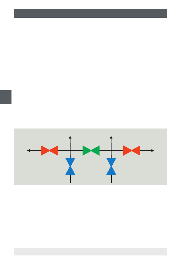
8. Desmontaje, devolución y eliminación de residuos
Modelos IV10, IV11
1. Para evitar picos de presión, cerrar lentamente la válvula de cierre
(azul).
2. Si la válvula está equipada con un oricio de purga, abrirlo con una
herramienta adecuada. Retire el tapón roscado/tornillo de purga (en
caso de existir).
Ahora se puede desmontar la válvula.
Modelos IV20, IV21
1. Para evitar picos de presión, cerrar lentamente la válvula de cierre
(azul).
2. Abrir la conexión de purga con una herramienta adecuada. Retire el
tapón roscado/tornillo de purga (en caso de existir).
ES
3. Abrir lentamente la válvula de purga (roja) para despresurizar la
válvula.
Ahora se puede desmontar la válvula.
Modelos IV30, IV31, IV50, IV51
Purgar (rojo)
Solo modelos IV5x
Bloquear
(azul)
Compensar
(verde)
(azul)
Bloquear
Purgar (rojo)
Solo modelos IV5x
1. Abrir la válvula de compensación (verde).
2. Para evitar picos de presión, cerrar lentamente las válvulas de cierre
(azules).
3. Retirar los tapones roscados/tornillos de purga (si los hay).
4. Sólo para el modelo IV5x: Abrir lentamente las válvulas de purga
(rojas).
Ahora se puede desmontar la válvula.
94 Manual de instrucciones válvulas de cierre y manifolds
14294094.01 10/2019 EN/DE/FR/ES
Page 95

8. Desmontaje, devolución y eliminación de residuos
8.2 Devolución
Es imprescindible observar lo siguiente para el envío del producto:
Todos los productos enviados a WIKA deben estar libres de sustancias
peligrosas (ácidos, lejías, soluciones, etc.) y, por lo tanto, deben limpiarse antes de devolver.
¡ADVERTENCIA!
Lesiones corporales, daños materiales y del medio
ambiente por medios residuales
Medios residuales en el producto desmontado pueden
causar riesgos para personas, medio ambiente e instalación.
▶
En caso de sustancias peligrosas adjuntar la cha de datos
de seguridad correspondiente al medio.
▶
Limpiar el instrumento, consultar el capítulo 7.3 “Limpieza”.
Utilizar el embalaje original o un embalaje adecuado para la devolución
del producto.
Información sobre el procedimiento de las devoluciones
encuentra en el apartado “Servicio” en nuestra página web
local.
8.3 Eliminación de residuos
Una eliminación incorrecta puede provocar peligros para el medio
ambiente.
Eliminar los componentes de los productos y los materiales de embalaje
conforme a los reglamentos relativos al tratamiento de residuos y eliminación vigentes en el país de utilización.
ES
14294094.01 10/2019 EN/DE/FR/ES
Manual de instrucciones válvulas de cierre y manifolds
95
Page 96

9. Datos técnicos
9. Datos técnicos
En el capítulo 2.1 “Descripción del funcionamiento” encontrará una ilustración de las posiciones de los siguientes componentes.
Especicación
Punta del eje No girable, poco desgaste
Asiento de la válvula Asiento de metal
Tamaño del oricio de la
válvula
ES
Material Estándar Opción
Piezas en contacto con el medio
Cuerpo de la válvula Acero inoxidable
Caja del bonete de la
válvula
Punta del eje
Estopada PTFE Grato
Piezas sin contacto con el medio
Manilla Acero inoxidable 304 Acero inoxidable 316/316L
Tuerca prensaestopas Acero inoxidable 316/316L
Contratuerca
Eje de la válvula
Manguito obturador
4 mm (0,16 in)
316/316L
■
Monel 400
■
Hastelloy 276
■
Otros a petición
96 Manual de instrucciones válvulas de cierre y manifolds
14294094.01 10/2019 EN/DE/FR/ES
Page 97

9. Datos técnicos
Condiciones de operación
Material de
estopada
PTFE 689 bar a 38 °C
Grato 420 bar a 38 °C
Presión de trabajo máx. admisible en bar
con temperatura en °C
276 bar a 204 °C
209 bar a 538 °C
Material de
estopada
PTFE 10.000 psi a 100 °F
Grato 6.000 psi a 100 °F
Presión de trabajo máx. admisible en psi
con temperatura en °F
4.000 psi a 400 °F
3.030 psi a 1.000 °F
La temperatura mínima para la que está diseñada la válvula es de -54 °C
(-65 °F).
Para temperaturas de servicio permanentemente bajas ≤ -54 °C
(≤ -65 °F) se requiere una versión especial.
El siguiente diagrama debe utilizarse para garantizar que la correlación
presión-temperatura admisible se mantenga durante el funcionamiento,
según el material de la estopada utilizado.
Para más datos técnicos véanse las hojas técnicas WIKA AC 09.19,
AC 09.21, AC 09.23.
14294094.01 10/2019 EN/DE/FR/ES
Manual de instrucciones válvulas de cierre y manifolds
ES
97
Page 98

9. Datos técnicos
Diagrama de presión y temperatura
700
(10153)
ES
600
(8702)
500
(7252)
400
(5802)
300
(4351)
200
Presión en bar (psi)
(2901)
100
(1450)
0
PTFE
Grato
Temperatura en °C (°F)
98 Manual de instrucciones válvulas de cierre y manifolds
14294094.01 10/2019 EN/DE/FR/ES
Page 99

14294094.01 10/2019 EN/DE/FR/ES
WIKA operating instructions, shut-o valves and valve manifolds
99
Page 100

WIKA subsidiaries worldwide can be found online at www.wika.com.
WIKA-Niederlassungen weltweit nden Sie online unter www.wika.de.
La liste des liales WIKA dans le monde se trouve sur www.wika.fr.
Sucursales WIKA en todo el mundo puede encontrar en www.wika.es.
WIKA Alexander Wiegand SE & Co. KG
Alexander-Wiegand-Strasse 30
63911 Klingenberg • Germany
Tel. +49 9372 132-0
Fax +49 9372 132-406
info@wika.de
www.wika.de
100
WIKA operating instructions, shut-o valves and valve manifolds
14294094.01 10/2019 EN/DE/FR/ES
 Loading...